1
1 Preparation for installation
Prior to installation
■ HiddenPower kit is released as semi-assembled. If the kit is not installed in accordance
with the guideline, it may cause malfunctioning, or performance issues. In order to prevent
product failure, contact HiddenPower distributors for precise installation advices.
Please note the kit is originally developed for road-tire bikes. Prior to installation,
check and maintain the designated tire pressure.
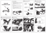
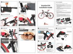
Brompton Kit
Installation Guide
■ Tools for assembly
- Six-angle wrench (1.5mm/2.5mm/3mm), Nipper, Scissors, (File and hacksaw if necessary)
■ The principle of HiddenPower kit
HiddenPower kit is operated by driving part, which is fixed to seat tube, together with
the friction roller that rolls on the road surface of tire. Thus the contacting point of roller
and tire is crucial in order to deliver the maximal motor power to the tire for the best
performance.
2 Understanding the principle (in the case of Standard kit)
This chapter will make installation process a lot easier. Understand the mutual relation
between tire and roller when the motor is on/off. And find the optimal point of motor
mount and install accordingly.
1-1. Separation of Motor & Mount
Motor set
The motor and the mount are released
Roller-fixing ring/
as semi-installed and placed on the
Cover/ Washer
Mount
pre-set position.
For installation, separate the mount
Dummy ring
from the motor set and detach rollerfixing ring, the cover, washer from the
motor set. Then attach Guide roller
(See bottom-right picture). The bolts
from the mount should be loosened
as shown in the picture below.
Separate here
Heat sink
*One bolt should stay fastened
Do not loosen
this bolt
Loosen the bolts
(Front: 2 bolts,
Back: 3 bolts)
Power
ON
Guide roller
※ It is recommended to understand the standard kit operation principle through
HiddenPower user manual before starting installation.
Friction roller slightly touches the road surface of the tire when the kit motor is off.
As soon as the motor runs, roller spins and gets lifted upward on the tire when roller
starts to spin faster than the tire. This process of shifting of roller delivers the best torque
for driving.
The roller spins on the road surface of tire and gets lifted upward automatically,
presses the tire strongly and delivers power.
1-2. Rubber ring cutting
1-3. Tire Air Pressure Adjustment
Power
Thin ring:
Cut in quarter
Charger
OFF
Battery bag
Power cord
Thick ring:
Cut in half
Adjust the air pressure to an optimum level.
Battery
Motor & Mount set
Electronic controller
& Accelerator
Cable ties &
Corrugated tube
Roller
Mount-fixing
rubber ring(2 types)
Guide roller
-2-
3 Cutting parts
3 Cutting parts – Folding lever
Removing the air pump guard
The tire automatically pushes the roller away to the original position when the motor
is off.
Have the rear wheel raised from the ground using
rear rack.
Fasten the mount, mount cover,
D ring to the frame by using
Six-angle wrench. Do not
over-tighten them in case of
moving the mount later for
repositioning.
Hacksaw
-4-
5 Driving Roller Assembly
4 Mount Positioning
Cutting the folding lever
28m
m
-3-
Assemble the roller in order as shown in the picture.
D ring
Fasten bolts
Mount cover
Washer
Roller
Check for the right
side of the roller
Roller lock ring
cover for installation
Air pump guard
Folding lever
Cutting device
Cut the folding lever by leaving it 28mm, and
file to smooth out the cutting surface.
*User can detach and re-install the lever
upside down (by turning 180 degree) without
cutting the lever.
By using cutting device, remove the air pump
guard and file to smooth out the cutting surface.
Six-angle wrench
As shown in the picture, place the
motor set into the mount.
( ) Insert the motor set
( ) The optimal installation point is
where the tire and the guide roller is
1mm apart from each other. When the
installation is completed, fasten the
bolts on the mount cover to secure. If
the roller is not installed properly as
shown below, loosen the bolts and
reposition ( ) the mount by moving
left/right to the optimal installation
point.
4 Mount Positioning
Cutting the fender
Fasten bolts
(bottom: 3 bolts)
Mount
Rubber ring
(cut in quarters)
5mm gap
Distance between the
tire and the guide roller: 1 mm
Dummy ring
Motor set
Assemble the driving roller cover and lock ring.
Heat Sink
Guide
roller
Rubber
Place the rubber ring (cut in quarters) on the
mount as shown in the picture and install it on
the frame.
Cut the fender by leaving 5mm gap on the
front, and file to smooth out the cutting surface.
-5-
The gap between the
roller and the tire is
too far – Adjust the
position again
-6-
The guide roller touches or
presses the tire – Adjust the
position again
-7-
-8-
6 Motor Installation
7 Frame-protector (rubber support) installation
Frame-protector (rubber support) installation
Roller form-up check
8 Electronic Controller Installation – Connecting cables
Connecting cables
Attach thick rubber ring (cut in half )
to protect the frame from rotational
movement of the motor set (decelerator).
Thick rubber ring (cut in half )
Cable tie
2
an
PAS Sensor
(Check for the
right side before installation)
Electronic controller cable
3
Check if they are
installed in
straight line.
Check from behind of the bicycle if the roller is
aligned with the tire as shown in the picture. If not,
loosen the mount cover to adjust the angle and
tighten it again.
Motor cable
Crank arm
8 Electronic Controller Installation
Installing motor and motor-fixing ring Assembly
Fix the Electronic controller with
motor cable to face downward, at
the seat tube with Velcro tape.
Six-angle wrench
Dummy ring
Motor set
Push the decelerator down to
the end and put the motorfixing ring into the opposite
side of the decelerator.
Hold the roller up with hand,
to touch the tire slightly,
Turn the motor-fixing ring
about 45 degrees to make
spring tense.
Fix the two spring-fixing bolts
with six-angle wrench. (in the
order of 1-2-3-4)
※ If the bolts are too tightened, it may damage the motor.
Bend the motor cable 90
degrees as shown with arrow
mark in the picture.
Put the cable tie (long one) into the opposite hole of the
logo side and install it onto the right handle grip. Tighten
the cable tie a little loosely and adjust to find the proper
point for your handle controlling. The optimal point of
installation is where user could control the accelerator
knob with his ring finger, keeping the same angle to the
brake lever. (See picture on bottom right corner). Fix the
accelerator cable with a cable tie along the brake cable.
Electronic controller
Magnet
PAS sensor & magnet should be placed where the chain stay
and the crank arm meets the closest.
The gap between should be less than 5 mm.
If it is greater than 5 mm, put a space block (remaining rubber
ring after installation) behind the PAS sensor and adjust the
distance as shown in the picture.
Accelerator
Sensor
detecting
area
Long
Cable tie
Logo-printed
side
Sensor
detecting
direction (with arrow)
Similar angle to brake lever angle
Motor cable
Magnet
Accelerator
While installing, make sure the sensor
detecting area and the magnet are facing each
other. Since the sensor detects the direction of
magnet’s movement, make sure the magnet
should move toward the direction of an arrow
with having the cable on the left side.
- 10 -
Magnet
Installation (image from inner side of the
crank arm): Silver magnet should be exposed
- 11 -
13 Test (Throttle type)
12 Test (PAS type)
Magnetic housing
Cable ties
Place it to control
with ring finger
(or middle finger)
10 Battery Installation
m
5m
Accelerator Installation
Battery connector
-9-
th
ser
o
l cl
tal
Ins
Frame protector
Cable tie
1
Tire
Roller
Space block for
distance adjustment
Attach the round connecting sockets of three cables
from the motor to the electronic controller.
Connect the middle cable, marked as
, from electronic controller to the middle cable from the motor.
Then connect cable
and
in order as guided in
the picture.
After finishing with connecting the cables, fix the cables with the enclosed cable tie to the frame protector.
Roller
Motor cable
9 PAS sensor Installation Guide (PAS only)
- 12 -
15 Cautions
■ This chapter will make installation process a lot easier. Understand the mutual relation
between tire and roller when the motor is on/off. And find the optimal point of motor
mount and install accordingly. The friction roller directly drives the road surface of the tire
Pack the battery inside the bag and hang it on
the top tube. Tighten one side of Velcro tape to
the top tube fullest until the bag does not
move. Cut out the rest of the tape.
Fix the other Velcro tape on the seat tube as
shown in the picture.
Turn the accelerator knob in clockwise completely to the end (‘0’ set), and then turn in counter
clock wise a little slowly. At this moment, rear
wheel should be apart from the ground.
11 Test – Battery Socket Connection
Turn the accelerator knob slowly in counterclock wise. Rear wheel should not touch the
ground during this.
Turn the pedal 2-3 times (PAS attached) to test
them.
If every part is assembled right, roller and rear
wheel will make friction and spin. If only motor
works and roller does not spin, go back to page
11 and refer to ‘8. Electronic Controller Installation – Connecting cables’. Try to change the
connection of cable
and
and test again.
Since the rear wheel is not touching the
ground, the roller will not get lifted upward to
the top point.
every part
part isis assembled
assembled right,
right, roller
roller and
and rear
rear
IfIf every
wheel will
will make
make friction
friction and
and spin.
spin. IfIf only
only motor
motor
wheel
works and
and roller
roller does
does not
not spin,
spin, go
go back
back to
to page
page
works
11 and
and refer
refer to
to‘12.
‘8. Electronic
Controller
Installat13
Motor Cable
Connection
&
ion
–
Connecting
cables’
.
Try
to
change
the
Cable Arrangement’. Try to change the conneconnection
of cable
and
test again.
ction
of cable
and and
and test
again.
Since the
the rear
rear wheel
wheel isis not
not touching
touching the
the ground,
Since
ground,
willlifted
not get
liftedto
upward
the
rollerthe
willroller
not get
upward
the topto
the top point.
point.
14 Cables
Press the end of the decelerator
slightly downwards
Tip to separate the battery socket:
User may find it difficult to separate the battery socket in the
beginning. Hold the grips with two hands and pull them apart
by utilizing your hands as leverage shown in the picture below.
Corrugated
tube for
motor cable
Cable ties
Check connector
for +/- signs
For safety reasons, fix all the cables by using enclosed cable
ties. Make sure the cables are fixed securely during folding/
unfolding the bike or during ride.
The easiest way to fix the accelerator cable with a tie is to
link along the brake cable (or the gear cable) from the
handle grip down.
Connect the battery in right +/sockets. If the direction changes,
power will not be delivered, thus
check the direction before
connecting.
- 13 -
- 14 -
- 15 -
- 16 -