1
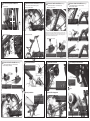
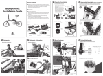
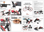
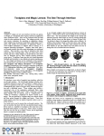
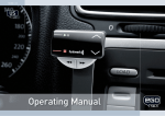
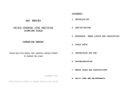
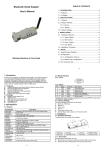
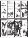
1 Preparation for installation
Prior to installation
1-1. Separation of Motor & Mount
■ HiddenPower kit is released as semi-assembled and can be installed on any bicycles with
the installation guide regardless of bicycle size.
If the kit is not installed in accordance with the guideline, it may cause malfunctioning, or
performance issues. In order to prevent product failure, contact HiddenPower distributors
for precise installation advices.
* This product is for general-purpose that can be installed on the Strida 16” and 18”, the
installation point may vary upon types of bicycles.
Start installation after checking and maintaining the designated tire pressure.
Strida Kit
Installation Guide
2 Preparation for installation
1-3. If wheel is 18”, motor mount needs to be replaced
(16” assembled when it is released)
Motor set
The motor and the mount
are semi-installed and
placed on the pre-set
position. For installation,
please detach the mount
from the motor set.
■ Tools for assembly
- Six-angle wrench (1.5mm/2.5mm/3mm), Nipper, Scissors, Soldering Iron, etc.
Mount
Motor mount for 16”
Dummy ring
D ring
Please check the direction
when replacing motor mount
Flush bolt
Motor mount for
18 inch wheel
D ring
■ The principle of HiddenPower kit
HiddenPower kit is operated by driving part, which is fixed to seat tube, together with
the friction roller that rolls on the road surface of tire. Thus the contacting point of roller
and tire is crucial in order to deliver the maximal motor power to the tire for the best
performance.
Heat sink
To install, separate the heat sink,
and assemble the mount as shown
in the picture on the right side.
Then put the guide roller on as
shown in the picture.
※ It is recommended to understand the standard kit operation principle through
HiddenPower user manual before starting installation.
Friction roller slightly touches the road surface of the tire when the kit motor is off.
As soon as the motor runs, roller spins and gets lifted upward on the tire when roller
starts to spin faster than the tire. This process of shifting of roller delivers the best
torque for driving.
Spring
Separate here
Distinguish the left /right by
looking at the spacing of the
edge and a bolt hole
Guide roller
If a bike has 18 inch wheel, its motor mount
should be replaced
Spring (spring point can be
moved if tire is changed to
Please check the direction
18 inches)
of the D ring’s protruding part and the
position of the flush bolt when assemble
This image is shown figure after replacement to
18” motor mount. As marked in the picture, please
pay attention to the point of flush bolt and
D ring’s, as shown in the picture
Mount
1-4. Rubber ring cutting
1-5. Tire Air Pressure Adjustment
Heat sink
Dummy ring
Assemble here
Battery bag
Power cord
Charger
1-2. Separation of mount cover
Adjust the air pressure to an optimum level.
After separating the motor set, loosen two bolts from the mount cover to separate
the cover and the rubber ring.
Mount cover
Battery
Motor & Mount set
Electronic controller
& Accelerator
Cable ties
Roller
Guide roller
Unscrew two bolts
Mount-fixing
-2-
3 Understanding the principle (based standard kit)
This chapter will make installation process a lot easier. Understand the mutual relation
between tire and roller when the motor is on/off. And find the optimal point of motor
mount and install accordingly. The friction roller directly drives the road surface of the tire
4 Mount Positioning
ON
Find installat
ion point by
moving left
and right
Have the rear wheel raised from the ground using
rear rack.
-3-
-4-
6 Driving Roller Assembly
5 Mount Assembly
Assemble the roller in order as shown in the picture.
There is only one installation point for Hidden Power Conversion Kit. The point, where the
tire and the guide roller is 1mm apart with decelerator moving up/down, is the optimal
motor mount installation point.
Power
Cut one side of rubber ring in horizontal
direction as shown in the picture.
Six-angle wrench
Six-angle
wrench
Place the rubber ring and the semi-assembled
motor mount at where the guide roller of the
decelerator is slightly touching the tire. Then find
the point and mark where the tire is 1mm away
from the radius of the decelerator.
Washer
Roller
Check for the right
side of the roller
Roller lock ring
cover for installation
Mount cover
Pre-cut
rubber ring
Tighten the mount set and the mount cover as shown in the picture.
Do not over-tighten it in case of moving the mount later for
repositioning.
Guide roller
After the mount cover bolt is tightened, install the motor set into the
mount. Swing the roller and check if the distance between the guide
roller and the tire is 1mm. When the mounting is completed, tighten
mount cover bolt till it is completely fixed. If the problems cause as
below pictures, loosen mount cover bolt and adjust the position
again.
Motor
mount
When the motor is on, roller spins on the road surface of tire and gets lifted upward
automatically, presses the tire strongly and delivers power.
감속기
Tighten the driving roller cover and lock ring.
Turning radius of decelerator
Power
OFF
Tire
Distance between
tire and guide roller : 1mm
Distance between tire
and guide roller: 1mm
The optimal motor mount installation point is where
the tire and the guide roller is 1mm apart from the
decelerator.
Guide roller
The tire automatically pushes the roller away to the original position when the motor
is off.
-5-
-6-
The gap between the
roller and the tire is
too far – Adjust the
position again
The guide roller touches or
presses the tire – Adjust the
position again
-7-
-8-
8 Electronic Controller Installation(cable installa-
7 Roller Form-up Check and Motor Fix
9 Electronic Controller Installation(Installing a
tion to outside/outward frame-regular)
Roller form-up check
10 Electronic Controller Installation(Installing a
cable inside the frame – For advanced user)
Electronic Controller Installation
cable inside the frame – For advanced user)
Drill a hole for cable in the frame
Drill a hole for cable in the frame
Accelerator
cable (when
installing
outside)
Tube to the
saddle
Wire
Roller
Battery cable
Accelerator
cable
Brake cable
Please refer to the
letter ‘HIDDEMPOWER’
on the electronic
controller
Tire
Check if they are
installed in
straight line.
Check from behind of the bicycle if the roller is
aligned with the tire as shown in the picture. If not,
loosen the mount cover a little, adjust the angle and
tighten it again as refers in page 7.
Motor cable
(3 starnd)
4mm Drill bit
Disconnect three wires from accelerator and
connect them to a piece of wire with solder job
(a piece of wire is not included with product).
Put the solder wire to the hole.
Six-angle
wrench
Heat
sink
Bolt
Spring
Motor-fixing
ring
Push the decelerator down to
the end and put the motorfixing ring into the opposite
side of the decelerator.
Hold the roller up with hand,
to touch the tire slightly,
Turn the motor-fixing ring
about 45 degrees to make
spring tense.
Fix the two spring-fixing bolts
with six-angle wrench. (in the
order of 1-2-3-4)
※ If the bolts are too tightened, it may damage the motor.
Bend the motor cable 90
degrees as shown with arrow
mark in the picture.
Take out cable and wire over the frame which is
upper of the saddle.
Have the battery connector face upward and fix them at
the proper position of seat tube with Velcro tape. The
point shown in the picture is the proper spot to fold and
unfold bicycle smoothly.
Using a 4mm drill screw drill a hole approximately 5-10 mm below the rear wheel frame where
the brake cable enters. First step is to drill perpendicularly then once the hole has been drilled
expand the size of the hole similarly to the image shown. After completing the steps above use
the circular line to smooth out the rough edges. This is done to avoid any damages to the wire
from the transmission by the drilled holes in the frame.
Accelerator cable Installation
Motor-fixing ring Assembly
Cable hole
Spring
Insert the cable to a cable protection spring
(already) given.
Separate cable from accelerator
Insert assembled spring to the saddle frame first,
and then insert a wire which is linked with cable
to the saddle frame hole.
Red(inside)
White(middle)
Black (outside)
Volume
Soldering iron
Lay out the accelerator wire that links from the handle
bar to the bicycle’s chair bottom then use the packaged
cable ties to secure the wire. Secure the wire from the
handle bar of brake’s cable and accelerator cable.
Roller
-9-
11 Electronic Controller Installation(Installing a
Unscrew the bolt which is under the accelerator
with a Philips screwdriver, and take the cover out.
- 10 -
Accelerator Soldering and Assembly
Put the cable tie (long one) into the opposite hole of the
logo side and install it onto the right handle grip. Tighten
the cable tie a little loosely and adjust to find the proper
point for your handle controlling.
Red(inside)
White(middle)
Black (outside)
Take cable out from the hole (near handle frame)
that the brake cable can go through.
If you pull out cables till end, arrange them like
shown in the picture.
- 11 -
14 Motor Cable Connection
12 Accelerator Installation
cable inside the frame – For advanced user)
Separate 3 cables from the volume using a soldering iron. Please remember the order of the
3 cables’ colors before separating, and solder
cables again after installing cables.
Wire
- 12 -
16 Test – Battery Socket Connection
Accelerator
Cable tie
Logo-printed
side
Similar angle to brake lever angle
Motor cable
Check connector
for +/- signs
Accelerator
2
Volume
1
3
Soldering iron
Three cables will be soldered to the volume.
Separate like shown in the picture, in the order
red, white and black from the inside
Electronic
controller
cable
Put a lid on the accelerator and tighten a screw
with a Philips screwdriver
13 Battery Installation
Electronic Controller Installation
Connect the battery in right +/sockets. If the direction changes,
power will not be delivered, thus
check the direction before
connecting.
17 Test
15 Motor Cable Arrangement
Put the battery inside the bag and hang it on
the rear bike rack. Tighten the Velcro tape to the
fullest so it does not move (so that it is stable).
Tighten the Velcro tape in the rear side, too.
Cut out the rest of the tape. Pull the battery
cable out to be seen battery socket like shown
in the picture.
Battery cable
Connect the round connecting sockets of three
cables from the motor to the electronic controller.
Connect the middle cable, marked as
, from
electronic controller to the middle cable from the
motor. Then connect cable
and
in order
as guided in the picture.
After finishing with connecting the cables, cover
the cables with the enclosed corrugated tube.
Tighten motor cable (3 cables each) to the bottom
frame with cable tie which was enclosed like shown
in the picture. Let loose the cables coming from
electronic controller to prevent cable damage when
you fold and unfold your Strida
Please refer to the
letter ‘HIDDEMPOWER’
on the electronic
controller
Motor cable
(3 starnd)
Have the battery connector face upward and fix them at
the proper position of seat tube with Velcro tape. The
point shown in the picture is the proper spot to fold and
unfold bicycle smoothly.
Turn the accelerator knob slowly in counterclockwise. Rear wheel should not touch the
ground during this operation.
Battery connector
- 13 -
- 14 -
- 15 -
every part
part isis assembled
assembled right,
right, roller
roller and
and rear
rear
IfIf every
wheel will
will make
make friction
friction and
and spin.
spin. IfIf only
only motor
motor
wheel
works and
and roller
roller does
does not
not spin,
spin, go
go back
back to
to page
page
works
15 and
and refer
refer to
to‘12.
‘14. Motor
Motor Cable
Cable Connection
Connection.&
13
Try toArrangement’
change the connection
of cable
and
Cable
. Try to change
the connetest again.and
ctionand
of cable
and test again.
Since
the
rear
wheel
is
not
touching
the
Since the rear wheel is not touching the ground,
ground,
willlifted
not get
liftedto
upward
the
rollerthe
willroller
not get
upward
the topto
the top point.
point.
- 16 -