1
12 Test – Battery Socket Connection
10 Battery Installation
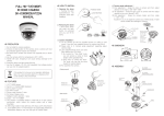
Prior to installation
★ Please read 5-2) Limitations in the User Manual prior to installation.
■ HiddenPower kit is released as semi-assembled and can be installed on any bicycles with
the installation guide regardless of bicycle size.
If the kit is not installed in accordance with the guideline, it may cause malfunctioning, or
performance issues. In order to prevent product failure, contact HiddenPower distributors
for precise installation advices.
* The kit is designed as univ
for various bicycles; the installation point may vary
upon type of bicycles.
Please note the kit is originally developed for road-tire bikes. Users should make sure if
at surfaced tire) and start installation after checking and
the bicycle tires are road tir
maintaining the designated tire pressure.
Standard Kit
Installation Guide
Top tube
Check
connector
for +/- signs
■ Tools for assembly
- Six-angle wrench (1.5mm/2.5mm/3mm), Nipper, Scissors, etc.
■ The principle of HiddenPower kit
xed to seat tube, together with
HiddenPower kit is operated by driving part
the friction roller that rolls on the road surface of tire. Thus the contacting point of roller
and tire is crucial in order to deliver the maximal motor power to the tire for the best
performance.
13 Test (Throttle type)
11 Fixing accelerator cable
※ It is recommended to understand the standard kit operation principle through
HiddenPower user manual before starting installation.
Friction roller slightly touches the road surface of the tire when the kit motor is o .
As soon as the motor runs, roller spins and gets lifted upward on the tire when roller
starts to spin faster than the tire. This process of shifting of roller delivers the best
torque for driving.
For safety reasons, arrange all the cables using cable ties.
Cable tie
Charger
Battery bag
Power cord
Battery
Motor & Mount set
Turn the accelerator knob counterclockwise.
If only motor works and roller does not spin, go
back to page10 ‘8. Electronic Controller
Installation’. Try to change the connection of
cable 1 and 2 .
- 13 -
Mount
rubber ring(3 types)
Magnet disk
- 14 -
-2-
2 Preparation for installation
1 Understanding the principle
15 Tip & Cautions
14 Test (PAS type)
Cable ties &
Guide roller
Corrugated tube
Electronic controller
& Accelerator
This chapter will make installation process a lot easier. Understand the mutual relation
nt of motor
between tire and roller when the motor is on/o . A
mount and install accordingly. The friction roller directly drives the road surface of the tire.
Tip to separate the battery socket:
Hold the grips with two hands and pull them apart by
utilizing your hands as leverage as shown in the picture.
2-1. Installation guide roller
Detach roller lock ring, dust
cover and attach guide roller.
(do not detach the washer)
Power
ON
Limit setting bolt
Turn the accelerator knob clockwise to the
end (‘0’set), and then turn the accelerator knob
counterclockwise a little slow.
When the motor is on, the roller
spins on the road surface of tire
and gets lifted upward
automatically, presses the tire
strongly and delivers power.
※Angle of roller’s lifting can
the
“limit setting bolt”.
Turn the pedal 2-3 times (PAS attached) to test
them.
ON
Washer
OFF
Dust cover
Roller lock ring
Guide roller
2 Preparation for installation
If only motor works and roller does not spin, go
back to page10 ‘8. Electronic Controller
Installation’. Try to change the connection of
cable 1 and 2 .
For 34.9mm
2-2. Separation of mount cover
For 31.8mm
Six-angle
wrench
For 27.2mm
Adjust the air pressure to an optimum level.
Have the rear wheel raised from the ground using
rear rack.
- 15 -
- 16 -
Limit setting
bolt
Three di erent sizes of rubber rings are
provided to fit any seat tube.
Select the optimal rubber ring, and adjust to
the seat tube diameter.
※ If the size of the seat tube is over 34.9mm,
please contact the distributor.
(Applies to few carbon frame models)
Unscrew the
bolt until the
tip of bolt does
not show.
Six-angle wrench
Unscrew two bolts
-3-
Mount cover
-4-
3 Mount Positioning
3 Mount Positioning
6 Roller Form-up Check and Motor Fix
When motor, roller and tires are located in a straight line, utmost power is passed.
Thus, it’s important t
tor mount using guide roller.
8 Electronic Controller Installation
Decelerator limit setting
Electronic controller installation
Tire
Tighten the limit setting bolt slowly until
the decelerator drops downward at certain
point.
If the decelerator doesn’t go down when
you tighten a bolt to the end, use spring
after cutting.
Six-angle wrench
Limit setting bolt
Maximum
friction position
1. Attach the Electronic controller at seat tube
tightly using the velcro tape.
2. Connect middle motor cable and middle
controller cable . And connect red motor
cable and red controller cable . And then,
Connect the remaining cables .
3. Cover the cables with the corrugated tube.
Guide roller
Distance between
tire and guide roller : 1~2mm
Motor cable
Decelerator
3
2
1
Electronic
controller
cable
Velcro tape
too far
Find installation point by
moving up and down motor mount
Corrugated
tube for
cable
arrangement
too close
7 Motor cap assembly
Roller form-up check
Accelerator Installation
rubber ring
Put the cable tie(long ones) as shown in the picture.
Install the accelerator onto the right handle grip.
Guide roller
Turning radius
of decelerator
Accelerator
Motor mount
Cable tie
Tire
Similar angle to brake lever angle
Check if they are
installed in
straight line.
Six-angle wrench
Guide roller
el
ar
f re
Ce
ro
nte
e
wh
Accelerator
If the guide roller is not aligned with the tire, loosen
the mount cover a little. And then adjust the angle
and tighten it again as refer to the picture above.
Install motor mount using rubber ring.
Motor cap
-5-
4 Driving Roller Assembly
-6-
Assembly
-9-
9 PAS sensor Installation Guide (PAS only)
5 Motor Installation
Motor
Place it to control
with r
Motor decelerator set
- 10 -
9 PAS sensor Installation Guide (PAS only)
Magnet disk installation
Sensor installation
Six-angle wrench
Motor
Spring
Washer
Roller
Check for the right
side of the roller
Roller lock ring
cover for installation
Bolt
Roller
?
ring
Push the motor decelerator set
decelerator in the direction of
the arrow and put the motorring into the opposite
side of motor decelerator set.
Hold the roller up with hand.
ring
Turn the motor
about 45 degrees to make
spring tense.
Fix the two spr
with six-angle wrench. (in the
order of 1-2-3-4)
※ If the bolts are too tightened, it may damage the motor.
Bend the motor cable 90
degrees as shown with arrow
mark in the picture.
?
Space block(3mm)
C
necessary
Space block(2mm)
Sensor
Double-sided tape
Both directions are possible
If use two space blocks
(2mm + 3mm)
?
Magnet disc
Bolt 2x5
Distance between
sensor and magnet disc:
install closer than 5mm
6 Roller Form-up Check and Motor Fix
Roller lock ring
Use space block to make gap closer than 5mm
between sensor and magnet.
Bolt 2x8
Sensor
The sensor's arrow mark
is facing the magnet.
Decelerator limit setting
Sensor
Motor mount
Six-angle wrench
Limit setting bolt
Magnet disk
Motor decelerator set
Diameter Ø 16mm
Pedal rotate
direction
(painted
arrow)
Diameter Ø 22mm
Diameter Ø 30mm
C
cessary
Sensor
cable direction
Distance between
sensor and magnet disc:
install closer than 5mm
Lift up the decelerator to the maximum point
-7-
-8-
- 11 -
- 12 -