1
Developer’s Guide
Nexio AMP® Protocol
Version 7.5
May 2014
Delivering the Moment
Nexio AMP® Protocol
Publication Information
© 2014 Imagine Communications Corp. Proprietary and Confidential.
Imagine Communications considers this document and its contents to be proprietary and confidential. Except for
making a reasonable number of copies for your own internal use, you may not reproduce this publication, or any
part thereof, in any form, by any method, for any purpose, or in any language other than English without the
written consent of Imagine Communications. All others uses are illegal.
This publication is designed to assist in the use of the product as it exists on the date of publication of this manual,
and may not reflect the product at the current time or an unknown time in the future. This publication does not in
any way warrant description accuracy or guarantee the use for the product to which it refers. Imagine
Communications reserves the right, without notice to make such changes in equipment, design, specifications,
components, or documentation as progress may warrant to improve the performance of the product.
Trademarks
6800+™, ADC™, CCS Navigator™, Channel ONE™, ChannelView™, ClipSync™, Delay™, D-Series™, D-Series DSX™,
Deliver the Moment™, Delivering the Moment™, FAME™, Farad™, G8™, G-Scribe™, HView™, IconMaster™,
IconLogo™, IconStation™, IconKey™, InfoCaster™, InfoCaster Creator™, InfoCaster Manager™, InfoCaster Player™,
InstantOnline™, Invenio®, Live-Update™, mCAPTURE™, Magellan™, Magellan CCS Navigator™, Magellan Q-SEE™,
MultiService SDN™, NetPlus™, NetVX™, NewsForce™, Nexio® G8™, Nexio AMP® ChannelView™, Nexio® Channel
ONE™, Nexio® ClipSync™, Nexio® Delay™, Nexio® Digital Turnaround Processor™, Nexio® Farad™, Nexio® GScribe™, Nexio® IconKey™, Nexio® IconLogo™, Nexio® IconMaster™, Nexio® IconStation™, Nexio® InfoCaster™,
Nexio® InfoCaster Creator™, Nexio® InfoCaster Manager™, Nexio® InfoCaster Player™, Nexio® InfoCaster Traffic™,
Nexio® InstantOnline™, Nexio® mCAPTURE™, Nexio® NewsForce™, Nexio® NXIQ™, Nexio® Playlist™, Nexio®
Remote™, Nexio®RTX Net™, Nexio® TitleMotion™, Nexio® TitleOne™, Nexio® Velocity ESX™, Nexio® Velocity
PRX™, Nexio® Velocity XNG™, Nexio® Volt™, OPTO+™, Panacea™, Platinum™, Playlist™, Predator II-GRF™, Predator
II-GX™, Punctuate™, Remote™, RTX Net™, QuiC™, Q-SEE™, SD-STAR™, Selenio™, Selenio 6800+™, SelenioNext™,
Selenio X50™, Selenio X85™, Selenio X100™, TitleMotion™, TitleOne™, Velocity ESX™, Velocity PRX™, Velocity
XNG™, Versio™, Videotek® SD-STAR™, X50™, and X85™ are trademarks of Imagine Communications or its
subsidiaries.
Altitude Express®, Connectus®, Enabling PersonalizedTV®, ICE® Broadcast System, ICE Illustrate®, ICE-Q®
algorithms, ICEPAC®, Imagine ICE®, Inscriber®, Inscriber® Connectus®, Invenio®, NEO®, Nexio®, Nexio AMP®,
PersonalizedTV®, RouterWorks®, Videotek®, Videotek® ASI-STAR®, Videotek® GEN-STAR®, and Videotek® HDSTAR® are registered trademarks of Imagine Communications or its subsidiaries.
Microsoft® and Windows® are registered trademarks of Microsoft Corporation. HD-BNC is a trademark of
Amphenol Corporation. Some products are manufactured under license from Dolby Laboratories. Dolby and the
double-D symbol are registered trademarks of Dolby Laboratories. DTS Neural audio products are manufactured
under license from DTS Licensing Limited. DTS and the Symbol are registered trademarks & the DTS Logos are
trademarks of DTS, Inc. © 2008-2010 DTS, Inc. All other trademarks and trade names are the property of their
respective companies.
Contact Information
Imagine Communications has office locations around the world. For locations and contact information see:
http://www.imaginecommunications.com/company/contact-us.aspx
Support Contact Information
For support contact information see:
Support Contacts: http://www.imaginecommunications.com/services/technical-support.aspx
eCustomer Portal: http://support.imaginecommunications.com
2014 Imagine Communications | All Rights Reserved
Page 2
Nexio AMP® Protocol
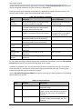
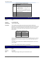
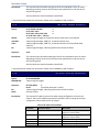
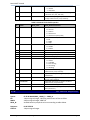
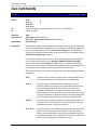
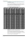
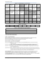
Revision History
Revision
Date
Description of Changes
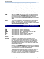
7.5
May 2014
7.0
August 2013
Rebrand as Imagine Communications
NOTE: With the addition of auto-input resolution
detection and the ability to separately record all four
major video resolutions on the same input, the legacy
Get and Set Record Parameter commands (C0 C0, C0
C1, C8 C1, C9 C1) are no longer valid when auto-input
detection is enabled (the default as of the Nexio 7.0
Software Release). Instead use the new Get and Set
Auto-Detect Record Parameters commands (C5 CF and
CF CF). In addition, the Get and Set Special Channel
Properties (C4 B1 and CF B1) commands for bit 20 to
get/set the audio routing input mask of a channel is
replaced by the Get and Set Auto-Detect Record
Parameters command.
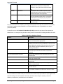
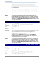
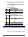
6.5
July 2012
B0 07 VDCP command supports new
VdcpActiveIdRequest registry to indicate a channel
is active if a clip is in the STILL state.
30 05 VDCP Status command includes new
extended status to indicate a stacked clip is ready to
play (PVW-READY)
New Channel Properties in the C4 B1 command to
indicate a channel’s current AFD mode for both
cases when a clip requires an aspect ratio
conversion on play out or not.
New mode for Get Disk Information (C1 C7) to
handle storage systems up to 1,000,000 hours
New protocol commands to manage audio track
routing, their profiles, and the dynamic selection of
these profiles: C2 56, CF 57, C1 16, and C1 17.
The Audio Track Routing introductory paragraph
has been expanded to include the new commands
available.
Removed references to old VR series of servers,
non-Unicode systems and systems with 8-byte clip
IDs – refer to earlier SDK releases to support those
platforms and features
Additions to Device Type Request (00 11) command
to support detection of Film Rate
Added MinFrame field to C8 4A command to report
the frame offset from the first video packet in a clip
to its actual start of message frame
New channel status indicators where the serve r
experiences excessive drift or media playback is
lacking video or audio.
Extended field 9 now called “Title”
2014 Imagine Communications | All Rights Reserved
Page 3
Nexio AMP® Protocol
Contents
Chapter 1: Introduction ______________________________________________ 9
About This Document ______________________________________________________________ 9
General Information _______________________________________________________________ 9
Control Communication____________________________________________________________ 10
RS-422 Control ___________________________________________________________________________ 10
UDP Control ___________________________________________________________________________ 11
TCP/IP Control ___________________________________________________________________________ 11
Dual LLM Control _________________________________________________________________________ 12
Chapter 2: Nexio Native Protocol _____________________________________ 13
Command and Response ___________________________________________________________ 13
Nexio Protocol Overview ___________________________________________________________ 14
Identifying System Configurations ___________________________________________________________ 14
Building a Database of Media _______________________________________________________________ 16
Managing Media Assets ___________________________________________________________________ 20
Cueing and Playing Media __________________________________________________________________ 22
Recording New Media _____________________________________________________________________ 24
Special Protocol Information ________________________________________________________ 26
Unicode Implementation __________________________________________________________________ 26
Video Format Codes ______________________________________________________________________ 27
Audio Track Router _______________________________________________________________________ 28
Short Clips Stacked Play Back _______________________________________________________________ 33
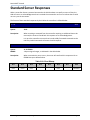
Standard Server Responses _________________________________________________________ 36
10 01
11 12
ACK ________________________________________________________________________ 36
NAK ________________________________________________________________________ 36
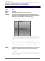
System Information Commands _____________________________________________________ 37
00
C4
C8
CF
C0
C0
CX
61
C8
11
B1
B1
B1
C3
C3
A4
0C
B0
Device Type Request ____________________________________________________ 37
Get Special Machine Properties _______________________________________ 38
Set Special Machine Properties _______________________________________ 43
Set Special Channel Properties _______________________________________ 44
Get Video Restriction __________________________________________________ 47
Get Max Extended ID Size ______________________________________________ 47
Get Current Time ________________________________________________________ 48
Get Current Time Sense _________________________________________________ 48
Set Controller ID _______________________________________________________ 49
Channel Status Commands _________________________________________________________ 50
C0 AC
C1 AC
A0 21
Get Logical Channel ____________________________________________________ 50
Set Logical Channel ____________________________________________________ 50
Get Device ID____________________________________________________________ 50
2014 Imagine Communications | All Rights Reserved
Page 4
Nexio AMP® Protocol
A8
C0
A8
61
C0
C0
C5
C8
C9
CF
C1
C0
C1
Cx
Cx
C1
CF
C2
CF
CE
C4
CF
C0
C4
CF
20
03
18
20
C0
C1
CF
C1
C1
CF
B7
50
51
52
53
54
55
56
57
67
6E
6E
C8
C8
B0
Set Device ID____________________________________________________________ 50
Get Loaded ID____________________________________________________________ 51
ID Status Request _______________________________________________________ 51
Get Channel Status _____________________________________________________ 51
Get Record Parameters __________________________________________________ 52
Get Extended Record Parameters _______________________________________ 53
Get Auto-Detect Record Parameters ___________________________________ 53
Set Record Parameters __________________________________________________ 54
Set Extended Record Parameters _______________________________________ 55
Set Auto-Detect Record Parameters ___________________________________ 56
Record Timecode Source _________________________________________________ 57
Get Audio Status ________________________________________________________ 58
Get Audio Levels ________________________________________________________ 58
Set Audio Input Volume(s) _____________________________________________ 58
Set Audio Output Volume(s) ____________________________________________ 59
Get Audio Routing Parameters _________________________________________ 59
Set Audio Routing Parameters _________________________________________ 60
Get Audio Routing Profile _____________________________________________ 60
Set Audio Routing Profile _____________________________________________ 61
Set Input Video ARC ____________________________________________________ 62
Get Genlock Properties _________________________________________________ 62
Set Genlock Properties _________________________________________________ 63
Get Channel Sync Mask __________________________________________________ 64
Set Channel Sync Mask __________________________________________________ 65
Lock Channel Control ___________________________________________________ 66
Mediabase Commands ____________________________________________________________ 69
A0
A0
C1
C0
C8
CF
CF
C8
CF
C9
CF
CF
C0
C8
CC
C8
C6
C1
CF
C1
C9
CF
CF
CF
CF
CF
CC
14
15
4C
4D
C3
C4
CA
4A
44
C3
CC
CB
CB
84
84
CA
CA
CA
66
66
C9
A0
A1
Bx
C2
85
B6
List First ID Handle ___________________________________________________ 69
List Next ID Handle ____________________________________________________ 69
List First ID List _____________________________________________________ 69
List Next ID List _______________________________________________________ 70
Get Extended ID from ID Handle _______________________________________ 71
Get ID Handle from Extended ID _______________________________________ 71
Rename Extended ID _____________________________________________________ 72
Get ID Metadata _________________________________________________________ 73
Set ID Metadata _________________________________________________________ 75
Get Extended Field _____________________________________________________ 76
Set Extended Field _____________________________________________________ 85
Find First ID Whose Extended Field Matches Criteria _____________ 85
Find Next ID Whose Extended Field Matches Criteria ______________ 86
Get Special ID Attributes _____________________________________________ 86
Set Special ID Attributes _____________________________________________ 87
Get Audio Track Information __________________________________________ 88
Set Manual Procamps ____________________________________________________ 88
Reset Manual Procamps __________________________________________________ 89
Set Manual Video ARC ___________________________________________________ 89
Reset Manual Video ARC _________________________________________________ 90
Get Slow Access Data Tag ______________________________________________ 91
Get Slow Access Metadata ______________________________________________ 91
Set Slow Access Metadata ______________________________________________ 93
Create Empty Media _____________________________________________________ 94
Create Empty Media with Extended ID _________________________________ 94
Create Subclip __________________________________________________________ 95
Redefine ID In Point ___________________________________________________ 96
2014 Imagine Communications | All Rights Reserved
Page 5
Nexio AMP® Protocol
CF
A8
C8
C8
C8
A8
CF
C8
C4
C4
C4
C4
C4
A3
10
4E
4F
4D
11
11
C5
B3
B4
BC
BD
A5
Redefine ID Timecode Bounds __________________________________________ 96
Erase ID __________________________________________________________________ 96
Erase ID __________________________________________________________________ 97
Erase ID with Transaction _____________________________________________ 97
Query ID as Erasable ___________________________________________________ 98
Erase Segment (Trim) ___________________________________________________ 99
Erase Segment (Trim) by ID ____________________________________________ 99
Consolidate ID _________________________________________________________ 100
Get Transaction Status ________________________________________________ 100
Get Transaction ID Handle ____________________________________________ 101
Get Transferred Field Count _________________________________________ 101
Get Transaction Result ________________________________________________ 101
Change Notification ___________________________________________________ 102
Cue Commands _________________________________________________________________ 104
2x
Cx
4x
4x
Cx
40
40
Ax
Ax
A0
A0
C1
C1
C0
C0
Ax
C4
40
40
31
86
14
15
AB
20
21
04
05
06
07
16
17
02
04
02
87
41
40
Cue Up with Data _______________________________________________________ 104
Fast Cue Up with Data _________________________________________________ 105
Preset In Point ________________________________________________________ 106
Preset Out Point _______________________________________________________ 107
Reverse Preset Out Point _____________________________________________ 107
Reset In Point _________________________________________________________ 108
Reset Out Point ________________________________________________________ 108
Preset Preview In Point ______________________________________________ 108
Preset Preview Out Point _____________________________________________ 109
Reset Preview In Point ________________________________________________ 109
Reset Preview Out Point ______________________________________________ 110
Select Preset Audio Routing Profile ________________________________ 110
Select Preview Audio Routing Profile_______________________________ 110
Next Cue _________________________________________________________________ 111
Play Next Cue___________________________________________________________ 111
Cue Up to Record _______________________________________________________ 112
Set New Out Point ______________________________________________________ 112
Set Auto Mode On _______________________________________________________ 113
Set Auto Mode Off ______________________________________________________ 113
Transport Commands ____________________________________________________________ 114
20
20
20
20
20
20
60
2x
2x
Cx
Cx
Cx
20
20
C4
C5
CF
00
01
02
0F
10
20
2E
1x
2x
00
01
02
61
60
CD
B7
88
Stop______________________________________________________________________ 114
Play______________________________________________________________________ 114
Record ___________________________________________________________________ 114
Eject ____________________________________________________________________ 114
Fast Forward ____________________________________________________________ 114
Rewind ___________________________________________________________________ 115
Get Variable Speed Sense _____________________________________________ 115
Set Variable Speed Forward ___________________________________________ 115
Set Variable Speed Reverse ___________________________________________ 117
Incremental Jog ________________________________________________________ 118
Jump Forward ____________________________________________________________ 118
Jump Backward___________________________________________________________ 118
Full E-E On _____________________________________________________________ 119
Full E-E Off ____________________________________________________________ 119
Timestamped Play and Record _________________________________________ 119
Timecode Triggered Record ____________________________________________ 120
Local Timeline Control ________________________________________________ 121
2014 Imagine Communications | All Rights Reserved
Page 6
Nexio AMP® Protocol
RAIDSoft Information Commands ___________________________________________________ 124
C0
C1
C0
CC
C0
C1
A0
C0
Cx
81
81
82
80
80
C7
1C
B2
C9
List First Disk ________________________________________________________ 124
List First Disk with Status _________________________________________ 124
List Next Disk _________________________________________________________ 125
Select Disk _____________________________________________________________ 125
Select All Disks _______________________________________________________ 125
Get Disk Information __________________________________________________ 125
Get Maximum Storage Length ___________________________________________ 127
Get Allocation Unit Size _____________________________________________ 127
Get ID File Size _______________________________________________________ 127
Chapter 3: VDCP Protocol __________________________________________ 129
General Information _____________________________________________________________ 129
Command And Response __________________________________________________________ 129
Media Identifiers ________________________________________________________________ 131
Fixed 8-Character IDs ____________________________________________________________________ 131
Variable Length IDs ______________________________________________________________________ 131
Unicode and Variable Length IDs ___________________________________________________________ 132
Nexio-Supported VDCP Command List _______________________________________________ 133
Server Response _________________________________________________________________ 134
04
05
ACK _______________________________________________________________________ 134
NAK _______________________________________________________________________ 134
System Commands_______________________________________________________________ 135
00/80 15 Delete Protect ID ______________________________________________________ 135
00/80 16 Undelete Protect ID ___________________________________________________ 135
Immediate Commands____________________________________________________________ 135
10
10
10
10
10
10
10
10
10
00
01
02
04
05
06
07
08
0A
Stop______________________________________________________________________ 135
Play______________________________________________________________________ 136
Record ___________________________________________________________________ 136
Still ____________________________________________________________________ 137
Step______________________________________________________________________ 137
Continue _________________________________________________________________ 137
Jog _______________________________________________________________________ 137
Variable Play___________________________________________________________ 138
EE Mode __________________________________________________________________ 138
Preset/Select Commands _________________________________________________________ 139
A0 1D
20/A0
20 20
20 21
20 22
20/A0
20/A0
20/A0
Rename ID _______________________________________________________________ 139
1F New Cop __________________________________________________________________ 139
Sort Mode _______________________________________________________________ 140
Close Port ______________________________________________________________ 141
Select Port _____________________________________________________________ 141
23 Record Init _____________________________________________________________ 141
24 Play Cue _________________________________________________________________ 142
25 Cue with Data___________________________________________________________ 143
2014 Imagine Communications | All Rights Reserved
Page 7
Nexio AMP® Protocol
20/A0 26 Delete ID _______________________________________________________________ 143
20 2B
% to Signal Full _______________________________________________________ 144
20/A0 2C Record Init with Data _________________________________________________ 144
20/A0 2E System Delete ID _______________________________________________________ 145
20 34
Audio In Level _________________________________________________________ 146
20 35
Audio Out Level ________________________________________________________ 146
20 39
Select Input ____________________________________________________________ 146
20 43
Disk Preroll ____________________________________________________________ 147
20 50
Copy File To ____________________________________________________________ 147
20 51
Delete File From _______________________________________________________ 148
20 52
Abort Copy File To ____________________________________________________ 148
Sense Commands ________________________________________________________________ 149
30 01
30/B0
30 05
30 06
30/B0
30 08
30 10
30/B0
30/B0
30/B0
30 17
30/B0
30/B0
Open Port _______________________________________________________________ 149
02 ID Next __________________________________________________________________ 150
Port Status _____________________________________________________________ 150
Position Request _______________________________________________________ 154
07 Active ID Request ______________________________________________________ 154
Device Type Request ___________________________________________________ 155
System Status Request _________________________________________________ 155
11 ID List __________________________________________________________________ 158
14 ID Size Request ________________________________________________________ 158
16 ID Request ______________________________________________________________ 158
Compression Settings Request ________________________________________ 160
18 IDs Added List _________________________________________________________ 162
19 IDs Deleted List _______________________________________________________ 162
VDCP Examples _________________________________________________________________ 163
Cueing and Playing ______________________________________________________________________ 163
Example 1 - Recording Media ______________________________________________________________ 163
Example 2 - Open-ended Recording _________________________________________________________ 164
Example 3 - Media Playback _______________________________________________________________ 165
Example 4: Playback of Multiple IDs ________________________________________________________ 165
Unsupported VDCP Command List __________________________________________________ 168
2014 Imagine Communications | All Rights Reserved
Page 8
Nexio AMP® Protocol
Chapter 1: Introduction
About This Document
This developers’ guide is intended to be used as a reference source for software development
companies wishing to manage the contents and control the recording and playback of Imagine
Communication’s Nexio™ Server product line. The information in this document is proprietary and
confidential and requires a signed and approved non-disclosure agreement.
This document defines and describes the protocols that are used to control the Low Level Module
(LLM), the application that serves as the backbone of the Nexio Server system. The LLM is the clustering
software that enables our video servers and the shared storage to communicate, share data, and tasks.
It is also to the LLM that controllers make a socket or serial connection in order to control the servers.
Chapter One of this document provides general information about the protocols and communications
with the Nexio servers. It covers the basic methods for connecting to a video channel through the LLM,
whether through an RS-422 connection or over Ethernet.
Chapters Two and Three cover the specific protocols supported by Nexio Servers: our own native
protocol in Chapter Two and the VDCP protocol in Chapter Three. Our native protocol implements
subsets of the following manufacturer's specifications:
Sony 9-Pin Protocol Document 9-966-979-04
Odetics Command and Control Specification Document 4136201-A
Nexio Control Protocol
VDCP Video Disk Communications Protocol
The Nexio implementation of the VDCP protocol is described based on the most recent VDCP manual
available to the public in February 2003. Additions to and omissions from the standard are noted where
appropriate.
The implementation of these protocol interfaces are constantly changing, being enhanced to better
serve our customers. Every effort is made to keep the protocol backward compatible as changes are
made. However there is no guarantee that all future enhancements and fixes will not affect a
controller’s current interface to the Nexio server. Check back regularly for updates to this document and
we strongly recommend gaining access to our new software releases as soon as they are available.
General Information
This document reflects the protocol implementation in the LLM as of May 2014. It includes the latest
protocol updates released with the Nexio AMP 7.5 Software Release.
2014 Imagine Communications | All Rights Reserved
Page 9
Nexio AMP® Protocol
While this manual is targeted toward the Nexio AMP and Volt Servers, most of the protocol commands
detailed in this manual are backward compatible to previous Nexio and VR products. For the most part,
there are no major differences in how the different servers respond to automation commands. They
make use of the same basic command sets, structures, and timeouts. The only real difference is in
feature development and bug fixes.
Where possible, this document will indicate when commands were first implemented and make note of
the applicable software release where they were introduced.
Control Communication
There are three pathways for a controller to communicate with the Nexio Servers: serially through RS422, or via Ethernet through TCP and UDP. And while the native Nexio Server protocol supports all three
of these, the VDCP specification only supports control over RS-422.
RS-422 Control
RS-422 communication with the Nexio servers is configured at 38400 baud, 1 start bit, 8 data bits, ODD
parity, and 1 stop bit. This method requires that the content of server/client conversations bears the
format described in the sections in Chapters Two and Three about Command and Response structures.
Nexio AMP Servers and later versions of the Nexio XS Servers use RJ-12 connectors for their RS-422
connections. All previous Nexio and VR Servers use 9-pin connectors.
Please consult the appropriate server’s User Manual for a description of pinouts and adapters available.
Operators should also consult the manual to learn how to set up each RS-422 connection to a particular
channel.
It’s important to understand that COM port 1 does not necessarily control Channel 1 on the server.
There are LLM settings that control the relationship between the channels under control and the COM
ports through which they can be controlled.
You can use the Nexio Config utility to determine which COM port controls which Nexio channel. There
is a special tab in Nexio Config called Automation/Serial for preparing the port control. For each serial
port there will be three protocol options: Sony, Harris, or Louth, plus the appropriate server channel to
assign to the port. “Sony” represents the Nexio Server native protocol. Both “Harris” and “Louth”
represent slightly different versions of VDCP. The difference is based on the interpretation of changes to
the VDCP manual. There was a change in the August 2000 manual in how a server should report its
current timecode position. The pre-2000 definition requires the protocol setting of "Louth". The 2000
and beyond definition requires a setting of "Harris".
Once set and the LLM is launched, the settings for each serial port and each server channel are hardwired. Even though there are protocol commands to select a different channel than the one assigned to
the port, the LLM will only control those ports as specified.
For example, in order to control a channel in the Nexio native protocol, a controller must select the
channel (Codec) that it wants to control. The Set Logical Channel (C1 AC) command is used for this
purpose. All subsequent commands on the same socket will be routed to the selected channel.
However, when controlling a Nexio Server using RS-422, a controller can only actually communicate with
the one specific channel per COM port setting. The controller must make a connection through a
different COM port in order to communicate with a different channel.
2014 Imagine Communications | All Rights Reserved
Page 10
Nexio AMP® Protocol
Similarly in VDCP protocol, a controller is required to first open a port (channel) with the Open Port (30
01) command and then select it with the Select Port (20 22) command. Even though each channel is
hard-wired to a COM port, the controller must follow the protocol specification.
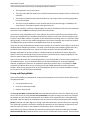
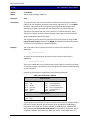
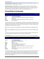
UDP Control
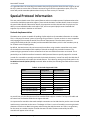
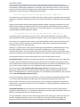
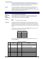
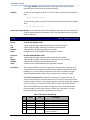
UDP communication to the server is conducted on port 331 unless otherwise specified and configured.
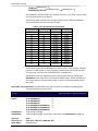
This method requires that the content of server/client conversations bear the following format:
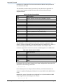
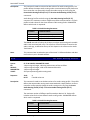
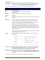
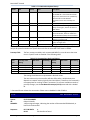
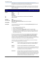
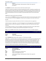
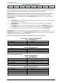
Table 1-1: UDP Datagram Format
Field
Format
Description
ID NUMBER
4 bytes unsigned integer,
MSB first
CHANNEL
1 byte unsigned integer
DATA0 – DATA(N-1)
N bytes, size depends on
command
This is the identification number of a
command or response. This field should have
different values for adjacent commands (for
example incremented mod 232 at every new
command), unless the command is a retry of
the previous command (i.e., resulting from a
response time out). In the latter case, the
retried command will bear the same
identification number as the original (failed)
command.
This field indicates the Codec to which the
command or response should be routed.
Valid channels are 0x00 (Channel 1), 0x01
(Channel 2), 0x02 (Channel 3), 0x03 (Channel
4).
This field contains either a command or a
response. It includes all parts except the
checksum. See the section on Command and
Response Structures for details on the
structure of commands and responses.
The controller is responsible for managing its own timeouts and retries. It should ignore any responses
that don't match the last command's identification. If the controller does not receive a response that
matches the last command's identification within the protocol's timeout, it may either retry the failed
command using the same identification number or proceed to the next command using a new
identification number.
If the server receives two or more consecutive commands bearing the same identification numbers, it
will only execute and respond to the first instance. After which it will simply return duplicates of the first
response for every subsequent instance without actually executing them. This is to give the controller
the option of retrying unacknowledged commands without the danger of having them executed
repeatedly by the server.
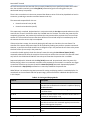
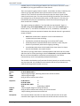
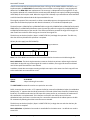
TCP/IP Control
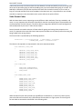
TCP/IP communication is conducted on port 557 of the server unless otherwise specified and
configured. This method requires that the content of server/client conversations bear the following
format:
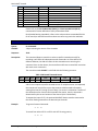
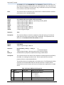
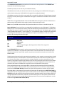
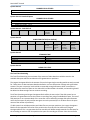
Table 1-2: TCP/IP Message Format
Field
Format
2014 Imagine Communications | All Rights Reserved
Description
Page 11
Nexio AMP® Protocol
Field
Format
Description
CMD-1
1 byte unsigned integer
CMD-2
DATA0 –
DATA(N-1)
1 byte unsigned integer
N bytes, size depends on
command or response
Contains Basic Command Group and Byte
Count
Command
Optional. One or more bytes containing data
required to act upon or further interpret the
specific command.
The checksum is not included.
For most command and control operations, the controller must select a channel against which it wants
to perform the task. This is done with the Set Logical Channel (C1 AC) command.
The controller is responsible for managing its own timeouts and retries. If for any reason a controller
crashes or cables become disconnected, the server will close the current connection and wait for a new
connection, at which time, the controller can reconnect.
Dual LLM Control
As of the Nexio 5.5.0 software release (LLM version 6.07.97.130), new support was added for servers
configured to operate with two instances of the LLM. In this special case, one LLM provides control over
the high resolution channels on the server (Nexio Server System) and the other LLM provides control
over the low resolution channels (Nexio Global Proxy System). This is the typical configuration for a
server recording new clips simultaneously into both high- and low-res systems.
Most controllers need not be concerned with the Nexio Global Proxy system or the information that
follows. It is listed here just in case the situation is encountered and questions are raised.
In a dual LLM control system there will be two sets of registry settings for configuring each individual
system: the existing registry branch under [HKCU\Software\ASC Audio Video\LLM] for the high-res LLM
and a new registry branch under [HKCU\Software\ASC Audio Video\LLM1] for the low-res LLM. In this
way specific configurations related to IP addresses, node numbers, domain letters, and such can be
clearly delineated between the two systems.
In addition there is a registry setting for providing an alternate port number for controlling the second
LLM: a DWord registry setting called “TcpPortOffset”. The value entered here is an offset value added to
the above stated port numbers for interfacing to the server. And even though the phrase “Tcp” is in the
registry name, it also applies to the UDP control port number.
Typically this registry would only be set for the low-res LLM1 registry, leaving the high-res control set to
the documented defaults. The TcpPortOffset value must be set to at least a value of 100 so that the
ports for both LLMs do not conflict with each other. For example, a setting of 100 applied to the LLM1
registry branch would indicate high-res control would remain on TCP port 557 and low-res control would
be available on TCP port 657.
By default the Nexio Config utility presets this LLM1 registry value to 100, even for servers that are not
configured for the Nexio Browse System. It is safe to leave this LLM1 registry branch as long as the
TcpPortOffset setting remains with its default value.
2014 Imagine Communications | All Rights Reserved
Page 12
Nexio AMP® Protocol
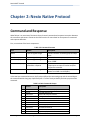
Chapter 2: Nexio Native Protocol
Command and Response
What follows is an overview of the Nexio Server Protocol command and response interaction between
the controllers and servers. Please see the VDCP section for more detail on that protocol's command
and response definition.
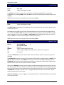
First, an overview of the basic components:
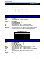
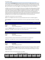
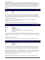
Table 2-3: Command Structure
Field
Format
Description
CMD-1
1-byte unsigned integer
CMD-2
Byte Count (BC)
1-byte unsigned integer
1-byte unsigned integer
DATA0 – DATA(N-1)
N bytes, size depends on
command or response
CHECKSUM
1-byte unsigned integer
Contains the basic command group and byte
count
Command
Contains byte count if CMD-1 bits 0 to 3 are
set to 1 "0xF"
Optional. One or more bytes containing data
is required to act upon or further interpret
the specific command.
The LSB of the sum of all the bytes in the data
stream from CMD-1 to DATA(N-1)
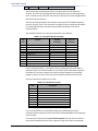
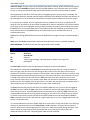
In the two-byte command structure, the first byte defines the command group and the second byte is
the command within that group. Specifically bits 4-7 of the first byte identify the basic purpose of the
command.
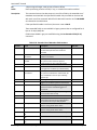
Table 2-4: Basic Command Groups
0
1
2
4
6
7
8
A
C
D
E
Source
Description
Controller
Server
Controller
Controller
Controller
Server
Server
Controller
Controller
Server
Controller
High level control & ID query
ACK/NAK & device ID
Mode and transport control
Editing and random access play setup
Sense requests
Sense return
ID data return
ID record/play
Extended commands
Extended sense return
Sequence play commands
2014 Imagine Communications | All Rights Reserved
Page 13
Nexio AMP® Protocol
F
Server
Sequence sense return
Nexio Protocol Overview
There are certain functions almost every controller using the Nexio Server Native Protocol must perform
in order to effectively manage and control the servers. The following pages attempt to detail some of
the recommended methods for connecting to and controlling multiple server channels in a Nexio Server
system.
There are a number of steps every controller should take before ever attempting to load a piece of
media into a channel and sending the play or record command.
1. Identifying the capability and purpose of every channel of every server under the controller’s
command
2. Retrieving the list of clips in the Nexio storage system and all their special properties
3. Manipulating the media, their metadata, and their special properties
4. Loading and playing media in a channel
5. Recording media in a channel
Identifying System Configurations
It’s the controller’s responsibility to learn everything it can about every server and every channel in the
system that is under its control. Depending on a controller’s role in a system, it may need to learn about
every channel in the system.
Information to retrieve should include:
The basic characteristics of the server system, the metadata available, any general information
about the media to be stored on the system, and the current and maximum storage limits of the
system.
Extra detail about the server channels available in the system, including the number of channels
per server available and any restrictions on those channels.
What the current status of each channel is, including if there is a clip loaded, the channel’s play
or record status, and whether anything is cued to play next.
There are a few ways to manage this system inspection:
One is manually. Inspect the equipment and software visually. Check with Imagine
Commubnciations technical support. Get a full report on the equipment installed and
maintained.
The second is programmatically. Below is a checklist of some of the various configuration
options to be aware of and the Nexio protocol commands that can be used to return the
information. The information is broken down according to what is applicable system-wide, what
is applicable on a server-by-server basis, and what is applicable within each server on a channelby-channel basis. It should be noted that much of this is not possible within the VDCP protocol.
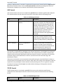
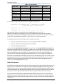
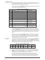
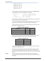
The following options are configurable on a server-by-server basis. Each individual server must be
queried for the following information.
2014 Imagine Communications | All Rights Reserved
Page 14
Nexio AMP® Protocol
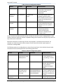
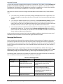
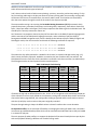
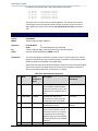
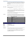
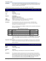
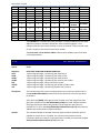
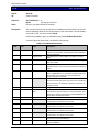
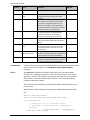
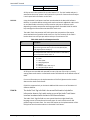
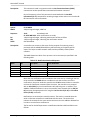
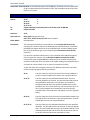
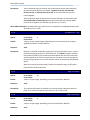
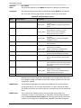
Table 2-5: Server Configuration Options
Options
Variables
Command
Additional Notes
LLM Version
ASCII String
C4 B1 00 00 00 02
Number of
Channels
2, 3, 4, 6, or 8
C1 AC 07 and
C0 AC
Media IDs
playable
On or off
C4 B1 00 00 00 08
Unicode
Interface
On or off
C4 B1 00 00 00 20
The LLM version number can give
the controller a clue as to the
most recent features
implemented.
First set the selected channel to
the highest possible number
(0x07, 0-based) and then check to
see what the resulting channel
reports it as
Nexio Timeline Playback Service
must be installed and started if
Media IDs are part of a system’s
workflow
Indicates if the server is
communicating with the
controller using Unicode
characters for metadata fields
that support them
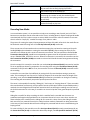
Once a controller has determined the number of video I/O channels a server is equipped with, it then
needs to determine what each channel is capable of doing. Some channels can only play clips, some can
only record, some can do both.
Most have limitations as to what type of clips may be played or recorded in those channels. For
example, one channel may be limited to support only SD clips while another might support all
resolutions including 1080p.
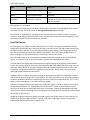
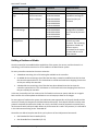
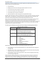
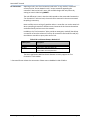
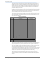
The following options are configurable on a channel-by-channel basis. Each individual channel under
automation control must be queried for the following information.
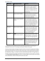
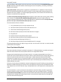
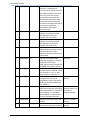
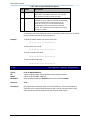
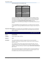
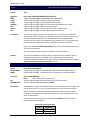
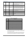
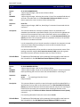
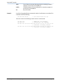
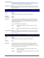
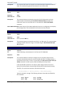
Table 2-6: Channel Configuration Options
Options
Variables
Command
Additional Notes
Channel Status
A series of returned
bytes based on status
modes queried
61 20
Current status of the
channel, whether it’s
cued, playing, in record,
etc.
Server Capabilities
1 byte variable
C4 B1 00 00 00 04
Codec Capabilities
1 byte for the first 3
commands and 4
bytes for the last
command
C4 B1 00 00 00 40 and
C4 B1 00 00 00 80 and
C4 B1 00 00 01 00 and
C4 B1 00 00 80 00
Video Formats and
Resolutions
Variable
C4 B1 00 02 00 00
As of the 6.5 Software
Release, determines the
server hardware
capabilities to support
1080p
Determines each
channel’s capabilities and
what types of clips can be
played or recorded in the
channel
Indicates a list of all video
formats and resolutions
2014 Imagine Communications | All Rights Reserved
Page 15
Nexio AMP® Protocol
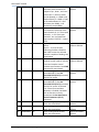
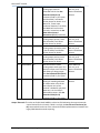
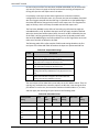
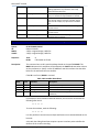
Options
Supported
Audio Routing and
Tags
Variables
32 bytes for all but
the last command
which is 16 bytes
Other Special
Channel Settings
Variable
Synced Channel
Configuration
Bitwise display
Command
C4 B1 00 08 00 00
C4 B1 00 10 00 00
C4 B1 00 20 00 00
C4 B1 00 40 00 00
C4 B1 00 80 00 00
C4 B1 01 00 00 00
C4 B1 00 00 02 00
C4 B1 00 00 08 00
C4 B1 00 01 00 00
C4 B1 00 04 00 00
C4 B1 02 00 00 00
C0 C8
Additional Notes
supported in the channel
Gets the audio routing
capabilities and tags for
record and play out
channels
Various special
configurations available
on a channel-by-channel
basis
Indicates if one channel
controls any other
channels. The controlling
application should only
direct transport
commands to the master
channel and not to the
slave channel
Building a Database of Media
Once the controller has established the capabilities of the system, the servers, and the channels it is
controlling, it will need to retrieve a list of the media on the Nexio Server system.
For every controller connection the server maintains:
A database containing a list of all existing IDs available to the controller.
An Added IDs List containing a list of IDs that have been created or modified since the last time
the controller queried this list. This list behaves as a FIFO stack with items dropping from the list
as they are read by the controller.
A Deleted IDs List containing a list of IDs that have been deleted since the last time the
controller queried this list. This list behaves as a FIFO stack with items dropping from the list as
they are read by the controller.
In this way a controller can first retrieve a list of all media on the server system and then on a regular
basis retrieve a list of the updates and deletions so as to keep up to date on all changes.
For every piece of media on the system, the LLM retains two separate IDs: an 8-byte ID handle and the
more user-friendly 32-character ID (also described as 64-byte ID). The 8-byte ID handle is used by most
protocol commands that affect the media. As a result, controllers must be prepared to associate every
32-character ID with its 8-byte handle. When the 32-character ID is used in this protocol, it is referred to
in the LLM command listing as the "Extended ID".
Controllers are able to keep the two IDs in sync by the use of two LLM protocol commands:
Get Extended ID from ID Handle (C8 C3)
Get ID Handle from Extended ID (CF C4)
2014 Imagine Communications | All Rights Reserved
Page 16
Nexio AMP® Protocol
The process of retrieving these two sets of identifiers for each piece of media in the system requires a
series of List First/List Next commands. Access to the database list of all clips is typically gained through
use of the List First ID Handle (A0 14) and List Next ID Handle (A0 15) commands, which return the 8byte ID handle for each ID on the system. Access to all of the lists is gained through the List First ID List
(C1 4C) and List Next ID List (C0 4D) commands. The latter set of commands can return the 8-byte ID
handles, the normal extended ID, or both.
The logical use of these commands is to first use the appropriate List First command followed by a series
of List Next commands until all IDs have been returned. Only one clip at a time is retrieved with every
use of these commands.
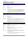
As a controller builds its list of IDs, it can also collect the metadata associated with every ID. The LLM
maintains two distinct storage areas for metadata: the normal set and an extended set. In addition, the
LLM maintains a list of special properties, or attributes, associated with each piece of media.
The Get ID Metadata (C8 4A) command is used to retrieve the normal set of metadata. The Set ID
Metadata (CF 44) command is used to change the normal set of metadata associated with an ID. The
following field descriptions are just an example of some of the fields available in the normal set of
metadata.
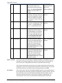
Table 2-7: Normal Set of Metadata
Field
Description
Video Format
Indicates an ID's video format (MPEG2, DV,
etc.) and aspect ratio
Value in Mb/s for only the video portion of
the media
Number of frames in the media
Video Bit Rate
Duration
Procamp Values
Children
Audio Tracks
Record Date
Kill Date
Source of Metadata
Based on record parameters of
media
Based on record parameters of
media
Based on record parameters of
media, changeable to smaller
values by controllers after the
fact
The Video Gain, Setup, Chroma Gain, and Hue Based on record parameters of
values associated with an ID
media, changeable by controllers
after the fact
Number of subclips made from this parent
Incremented as subclips are
clip
created from the ID
Number of discreet audio tracks
Based on record parameters of
media
16-bit number to indicate month, day, and
Set at record time of media by
year the media was recorded. This field
LLM
continues to exist even though it has been
superseded by an extended field
16-bit number that pre-determines the day
User-entry field, settable at
the media is scheduled to be labeled as
record time and changeable any
"expired". The media does not actually get
time later
deleted or become disabled on the indicated
day
For more detail, including a complete listing of the normal set of metadata, review the Get ID Metadata
(C8 4A) command in the command listing below in this chapter.
The extended set of metadata is retrieved using the Get Extended Field (C9 C3) command. However this
command retrieves the extended fields one field at a time. A separate command must be sent to
2014 Imagine Communications | All Rights Reserved
Page 17
Nexio AMP® Protocol
retrieve each field the controller is interested in retrieving. The Set Extended Field (CF CC) command is
used to change the metadata in one of the fields in the extended set.
Unlike the normal set of metadata, many fields in the extended set support Unicode characters. The
following table includes some of the extended fields used most often.
Table 2-8: Extended Set of Metadata
Field
Description
Source of Metadata
Record
Date/Time
Video Info
64-bit field storing the time and date stamp
of when the media was recorded
128-bit field storing extended video
information indicating such things as video
resolution, format and frame rate
UNICODE field indicating the individual
logged in to the Nexio system at record time
Automatically set at record time
of media by LLM
Automatically generated by LLM
User Name
Description
Agency
User-definable
Field #1
User-definable
Field #2
User-definable
Field #3
User-definable
Field #4
UNICODE user entry text field for storing
detail about media (up to 120 characters)
UNICODE user entry text field for storing
detail about media (up to 15 characters)
UNICODE user entry field (up to 25
characters)
UNICODE user entry field (up to 25
characters)
UNICODE user entry field (up to 25
characters)
UNICODE user entry field (up to 25
characters)
Automatically recorded by Nexio
user applications such as NXOS
and Velocity at record time
User entry field
User entry field
User entry field
User entry field
User entry field
User entry field
For more detail including a complete listing of the extended set of metadata, review the Get Extended
Field (C9 C3) command in the command listing below in this chapter.
In addition to metadata, there are also some special attributes available for every clip in the system.
These are useful for a controller to detect special properties associated with a clip. It’s also a good
indicator to know which IDs the controller can ignore.
Use the Get Special ID Attributes (C8 84) command to retrieve an ID’s special properties. The following
table includes some of them:
Table 2-9: Special Attributes
Value
Attribute
Description
0x0001
Delete protected
0x0002
Sliding ID
0x0004
Macro ID
The ID is protected from deletion until this
attribute is unset
Indicates a circular recording in which the
length is preset and material is automatically
deleted from the front as it is recorded on
the back
Indicates the media is a timeline made up of
pointers to other pieces of media, such as a
Media ID
2014 Imagine Communications | All Rights Reserved
Page 18
Nexio AMP® Protocol
0x0010
Project File
0x0020
Invisible ID
0x0200
Not Ready to Play
0x0400
Not Ready to Transfer
Indicates a special file used by editing
applications to represent a container of
timelines, always with the Invisible attribute
set
Indicates the file is hidden from the normal
media database. Most controllers should not
need to keep track of invisible files.
Indicates the first audio buffer of the media
has not yet been written to disk. A controller
should wait to load and play any clips when
this attribute is set.
Indicates the ID is currently in record or being
written to disk
The special attributes are cumulative, meaning media may have more than one attribute. For example,
an ID with an attribute value of 0x0031 is an invisible (0x0020) project file (0x0010) that is delete
protected (0x0001).
A controller can use the Set Special ID Attributes (CC 84) command to set some of these properties.
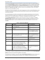
What follows is an example using the above Nexio protocol commands for building a database of media.
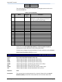
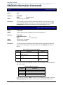
Table 2-10: Building a Database of Media
Protocol
Description
C8 B1 00 00 00 02 00 00 00 02
If not already established, sets up the interchange of data
to be in Unicode, where appropriate
Retrieves the first ID in the system. Mode 21 retrieves both
the 8-byte ID handle and the extended ID at the same time.
More traditional methods of ID retrieval use A0 14 to get
the first 8-byte ID handle followed by C8 C3 to get its
matching extended ID.
Retrieves the normal set of metadata associated with the
specified 8-byte ID handle retrieved in the previous
command
Retrieves the metadata for the specified clip in the first
extended field
Retrieves the metadata for the specified clip in each of the
remaining extended fields
Retrieves the special attributes associated with the
specified clip
Retrieves the next ID in the system including its 8-byte ID
handle and extended ID
Retrieves the normal set of metadata associated with the
next ID in the list
Continue this cycle of retrieving the next ID in the list and
its associated metadata until the server returns no more
IDs
C1 4C 21
C8 4A 25 30 30 30 30 31 32 33
C9 C3 25 30 30 30 30 31 32 33 00
C9 C3 25 30 30 30 30 31 32 33 nn
C8 84 25 30 30 30 30 31 32 33
C0 4D
C8 4A 25 30 30 30 30 31 32 34
…
Once the database of media is built, the controller then needs to keep up-to-date on any changes made
to the list of clips. For each controller connected, the Nexio server keeps in memory a list of all
additions, modifications, and deletions to the database.
2014 Imagine Communications | All Rights Reserved
Page 19
Nexio AMP® Protocol
It is up to the controller to request those changes on a regular basis. This is done via the List First ID List
(C1 4C) and List Next ID List (C0 4D) commands, selecting one of the Added List or Deleted List modes.
The Added List includes both new clip additions and existing clip modifications. It is up to the controller
to determine if the ID listed in the Added List is a new clip or a modified clip.
How often the controller checks for changes to the database can be handled in any of three different
ways:
It can check every x number of seconds by sending the C1 4C command on a regular basis. The
frequency should be no more often than every 2.5 seconds. This is how most Nexio applications
operate.
It can watch the Added and Deleted bits provided by the Get Channel Status (61 20) command.
If a controller is regularly checking channel status, retrieval of the tenth status byte will let it
know if there are new clips in the Added or Deleted Lists. Once notified, the controller then uses
the C1 4C command to retrieve which clip (or clips) was added to the indicated list.
It can set up an automatic notification from the Nexio server whenever a clip has been added to
the Added or Deleted Lists. This is done using the Change Notification (C4 A5) command with
masks 1 and 2 set. Once notified, the controller then uses the C1 4C command to retrieve which
clip (or clips) was added to the indicated list.
As the controller receives the name of an ID that was added or modified, it should use the same set of
metadata retrieval commands it used to build the original database of media.
Managing Media Assets
Once a controller has collected all the relevant information about each piece of media on the system, it
will need to organize those assets such that any future actions involving those assets are appropriate.
For example, it is up to the controller to know the configuration of every server channel. If the controller
loads an HD clip into an SD channel that is not prepared to down-convert the HD clip, there could be a
server failure.
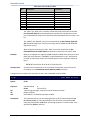
Therefore, the first step in organizing the database of media (MediaBase in NXOS) is identifying the
different types of clips on a system based on the three commands used in the previous section, the Get
ID Metadata (C8 4A), Get Extended Field (C9 C3), and Get Special ID Attributes (C8 84) commands.
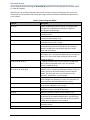
The following table reviews some of the different characteristics and types of media on the Nexio SAN,
how a controller can determine the information, and why it’s important.
Table 2-11: Identifying Media
Media Type
Detecting Via Protocol
Importance
Parent ID
C8 4A command
Response data bytes 28-29
Subclip
C8 4A command
Response data bytes 00-07
Audio-Only Clip
C8 4A command
Response data byte 8
Determines if the ID has any subclips
(child IDs) which protect it from
deletion
If the data response is different from
the ID’s the 8-byte ID handle, a
controller can determine the ID is a
subclip which is merely a pointer to a
piece of a Parent ID
A value of 0x15 indicates a clip that has
no video stored in the file, only audio
2014 Imagine Communications | All Rights Reserved
Page 20
Nexio AMP® Protocol
Media Type
Detecting Via Protocol
Importance
Empty ID
C8 4A command
Response data bytes 16-19
Media ID
C8 84
Response Mask of 0x0004
Consolidated ID
C8 84
Response Mask of 0x0040 or
0x0044
Looping Record
(Sliding ID)
C8 84
Response Mask of 0x0002
Looping ID
C8 84
Response Mask of 0x0100
Hidden Files
C8 84
Response Mask of 0x0020
If the data response is 1, indicating an ID
with duration of 1 frame, and all the
rest of the ID’s attributes indicate a
normal clip, a controller can determine
that the file is an Empty ID, which is a
placeholder file created to reserve the
ID for future use
Identifies an ID that is a Media ID,
essentially an EDL that includes pointers
to other Parent IDs. The Timeline
Playback service is required on servers
that load and play Media IDs.
Identifies a Parent ID that has had its
entire media except for those areas
protected by subclips erased from the
storage. If a controller loads and plays a
consolidated ID, those erased areas will
not play out. Instead depending on how
the clip was consolidated it may play
black in those areas or skip them.
Identifies an ID that is a circular
recording in which the length is preset
and material is automatically deleted
from the front as it is recorded on the
back. These IDs are typically used for
delay-to-air programming or for
creating a series of subclips.
Identifies an ID that will play in a loop if
loaded and played in a channel. Once it
reaches its last frame, it will seamlessly
transition back to the beginning of the
clip.
Identifies IDs that will normally not
appear in the List First/Next lists unless
specially requested by a controller with
the C8 B1 command. Hidden files are
usually system files used by editing
applications.
It is essentially up to the individual controller to know what type of system it is controlling, the
configuration of the server it is controlling, and the types of media on that system.
It’s also up to the controller to manage the amount of material on the Nexio storage system and when
some of that media should be removed to make room for more. The Nexio system includes a metadata
field called the “Kill Date”. This is purely an advisory field and does not actually delete the material on
the indicated date. However, a controller can use it to help indicate when media is no longer required.
The Nexio protocol actually includes three different Erase ID commands. The most useful to a controller
is the Erase ID with Transaction (C8 4F) command. It provides feedback to the controller as to the status
of the media deletion, whether it failed, and if it didn’t, why it didn’t.
2014 Imagine Communications | All Rights Reserved
Page 21
Nexio AMP® Protocol
There are four primary reasons why an attempt to delete media fails:
The clip doesn’t exist on the system.
The clip is protected from deletion by a subclip. Sometimes these subclips can be invisible to the
controller.
The clip has the Delete Protect special attribute set. This requires that a controlling application
has set the attribute.
The clip is currently loaded in a server channel and the clip protection logic is enabled on the
server system. This requires specific LLM registries be set.
Based on the controller’s collection of the database of media, it should know if the first three conditions
exist. And if not, the C8 4F command will provide that information.
In the case of a clip protected by one or more subclips, the controller would first have to delete all the
parent clip’s subclips before it can delete the parent clip. Keep in mind, some of those subclips may be
invisible. These hidden subclips are typically a result of the parent clip being active in a Velocity or other
editing project. In that case, the media management of the system must take into account the removal
of outdated editor projects before the outdated parent clips can be removed.
In the case of a clip protected by the Delete Protect attribute, the controller has the ability to unset that
attribute before attempting to delete it. Just keep in mind that there was probably a good reason why
the Delete Protect attribute was set. Typical uses of this attribute are by the Nexio MOS Playlist
Manager application for all clips currently in a loaded rundown, by the Nexio FTP Server application
while it is currently transferring the clip from one server system to another, and by an application user
who has reason to want to protect the clip from deletion.
Last is the case where the clip is protected because it is currently loaded in a server channel somewhere
on the Nexio system. This is an automatic feature to prevent the deletion of a currently loaded ID.
However, by default this feature is not enabled on most Nexio systems. But if it is enabled, the C8 4F
command will indicate which server currently has the clip loaded and which controller connection
loaded it. Other than going to that server and unloading the clip, there is no direct method for clearing
the connection so that the clip may be deleted.
Cueing and Playing Media
There are three different commands for cueing an ID for playback, each of which has four different sets
of usage parameters:
Cue Up with Data (2x 31)
Fast Cue Up with Data (Cx 86)
Preset In Point (4x 14)
The Cue Up with Data and Preset In Point commands behave exactly the same. The fastest way to cue
an ID in the server is by using the Fast Cue Up with Data command. As long as the channel is prepared
for playback, this will cause an instantaneous cue to field 1 of the requested frame. The drawback for
this speed is that the latency of a subsequent play command is increased, meaning that after the Play
(20 01) command, the video might start rolling a few milliseconds later than the controller is expecting.
This command is typically only used for checking the contents of an ID by allowing an operator to load
and look at the first frame. It was created to save processor time in such instances.
Once cued by any of these methods, the controller should check the channel’s status bits via the Get
Channel Status (61 20) command until the server returns a CUED status for the channel. The PST IN and
2014 Imagine Communications | All Rights Reserved
Page 22
Nexio AMP® Protocol
PST OUT bits also alert the controller if the currently loaded clip has a specified In and Out Point. After
that, the controller need only send a Play (20 01) command to get the ID rolling (after the predetermined latency has passed).
There is also a mechanism in the server protocol that allows a series of IDs to be played back-to-back in
succession, producing a seamless transition between each clip.
The commands responsible for this are:
Preset Preview In Point (Ax 04)
Preset Preview Out Point(Ax 05)
This sequenced, or stacked, playback works in conjunction with the Cue Up commands where one clip is
cued into the “Preset” slot and the other clip is loaded into the “Preview” slot. After the preset clip has
completely played out, the preview clip becomes the new preset and the preview slot is free to accept
another ID. This mechanism ensures that there will be an ID cued and ready for immediate play out at
the moment that the current clip has completed.
If the preview slot is empty, the currently playing clip will stop at its Out Point, less one frame. The
contents of the preset and preview slots can be replaced by sending new preset or preview commands.
However, a controller should be careful not to change the clip in the preview slot too close to the preset
Out Point of the clip currently in the preset slot.
A controller should regularly check the channel’s status bits using the Get Channel Status (61 20)
command to determine when the transition from one clip to another has occurred. The controller need
only look for the PVW IN and PVW OUT bits to drop to know that the preview slot is available.
Sequenced playback is initiated with the Play (20 01) command. As mentioned, when the preset clip
finishes playing, there is an automatic transition to the preview clip if one exists. A controller can trigger
a premature transition to the next clip with the Next Cue (C0 02) command. Sequenced playback is
terminated with a Stop (20 00) command or no more clips loaded in the preview slot.
What follows is an example using Nexio protocol for cueing and playing media in a stacked playlist. For
more detail on the commands and their proper usage, please consult their individual descriptions later
in this chapter.
Table 2-12: Cueing and Playing Media
Protocol
Description
C1 AC 00
Selects the desired channel to control. This assumes the
controller has verified that the channel is capable of playing
the desired media.
Sets the channel into auto mode, clearing the preset bits of
In and Out Points
Checks the current status of the channel to ensure that it is
in a state to load and play a clip
Cues up the specified clip to its first frame
Checks the channel status until the cued bit is set. A
controller should use this command regularly to ensure the
channel is doing what it expects.
Plays the cued clip
Sets the Out Point of the currently playing clip to its last
frame
40 41
61 20 0F
28 31 25 30 30 30 30 31 32 33
61 20 0F
20 01
40 15
2014 Imagine Communications | All Rights Reserved
Page 23
Nexio AMP® Protocol
A8 04 25 30 30 30 30 31 32 34
A0 05
61 20 0F
A8 04 25 30 30 30 30 31 32 35
Stacks the specified clip in the channel in preparation for
play out once the currently playing clip finishes
Sets the Out Point of the stacked clip
Checks and verifies the status of the channel. When the
first playing clip reaches its end, the stacked clip will
automatically start playing and the preset preview status
bits will drop.
With the preset preview channel clear, another clip can be
stacked and ready to play next
Recording New Media
In a normal Nexio system, it is not possible to simply start recording a new clip with just its ID. That’s
because most transport control commands on the server, including Record, require the 8-byte ID handle
associated with the clip in order to cause an action. What the controller must do instead is first create
what is called an “empty ID,” a media file empty of any video or audio.
The process of creating the empty ID auto-generates an 8-byte ID handle, after which the media file can
be filled with material through one of the Cue Up To Record (Ax 02) commands.
There are two sets of commands used to create these empty IDs: one based on creating an 8-byte ID
handle (CF Bx) and one based on creating the extended ID (CF C2). After creating the empty ID, the
controller must follow up with a series of transaction commands. The first transaction command, Get
Transaction Status (C4 B3), should be sent repeatedly at greater than 50 millisecond intervals until it
returns TRANSACTION_SUCCESS or an error. When the transaction is successful, the controller uses the
Get Transaction ID Handle (C4 B4) command to retrieve the ID handle that was auto-generated during
the transaction.
Once the empty ID is created, the controller can use the Cue Up to Record (Ax 02) command to load the
file in an appropriate channel in preparation for recording. After using the Get Channel Status (61 20)
command to verify that the REC bit is set, the controller can issue the Record (20 02) command to start
the recording.
A controller can record the clip indefinitely by cueing the ID for record without setting a preset out
value. The recording will not stop until it is explicitly stopped. If the controller knows the length of the
recording, it can issue the Preset Out Point (4x 15) command any time before or during the recording.
The recording will automatically stop at the specified preset Out Point.
The server is also capable of recording “Sliding IDs,” also known as “Looping Records”. These are media
that record without end but only use up a specific amount of disk space. When the specified duration is
reached, the record algorithm will loop back around to the front and begin recording over the front of
the ID with new material. In this way, a controller can record a clip that never grows beyond its specified
length.
Sliding IDs are useful for delay recordings in which a satellite feed is recorded into the server at a
predetermined length and played back out on a separate channel an hour or more later. Another use
allows subclips to be created from the sliding IDs as it records in a loop. Even as the sliding ID records
back over itself, any material from which a subclip has been made is protected from being overwritten.
In this way only the material desired from the sliding ID is preserved and the rest is released during the
looping record.
To create a sliding ID, the controller must first Cue Up to Record (Ax 02) a newly created empty ID, set
the Preset Out Point (4x 14) to indicate the desired loop length, then Set Special ID Attributes (CC 84)
2014 Imagine Communications | All Rights Reserved
Page 24
Nexio AMP® Protocol
for the sliding bit before executing the Record (20 02) command. The recording will not terminate unless
it is explicitly stopped.
What follows is an example using Nexio protocol for creating a new clip and putting it into record. For
more detail on the commands and their proper usage, please consult their individual descriptions later
in this chapter.
Table 2-13: Recording New Media
Protocol
Description
C1 AC 00
Selects the desired channel to control. This assumes the
controller has verified that the channel is capable of
recording the desired media.
Sets the channel into auto mode, clearing the preset bits of
In and Out Points.
Checks the current status of the channel to ensure that it is
in a state to load and play a clip.
Retrieves the channel’s record parameters to determine if
it matches the controller’s needs.
If a change is needed, this sets up the channel for the
record parameters the controller desires. This example
specifies an MPEG2 I-Frame 50 Mb/s clip with 4 audio
tracks and VBI enabled.
Retrieves the channel’s record video format code and HD
pixel aspect ratio- an important additional step to verify the
channel is in the correct video resolution and other HDrelated parameters.
If a change is needed, this sets the channel’s record video
format code and HD pixel aspect ratio. This example
specifies a 1080i NTSC clip.
Creates an empty ID with the specified ID, in this case,
“ABCDE” sent in Unicode. By sending 8 null bytes for the ID
handle, the server will automatically create a unique ID
handle. The server will return a transaction ID to the
controller: “00 00 00 01” in this example.
Requests the status of the empty ID creation. When the
status changes from pending to success, the controller can
request the new ID handle automatically created.
Retrieves the new 8-byte ID handle created during the CF
C2 command: %000012 in this example.
Cues up the new ID for recording with a start time code of
00:00:00:00 in drop-frame NTSC timecode.
Checks the channel’s status until the cued bit is set.
Sets the out point (and therefore eventual duration) of the
clip about to be recorded to 00:00:15:00 in the NTSC dropframe timecode format. This command can be sent before
or after the recording has actually started.
Checks the channel’s status to verify the clip’s preset In and
Out Points are set.
Puts the channel into record.
40 41
61 20 0F
C0 C0
C8 C1 03 01 01 32 00 00 04 01
C4 B1 00 00 01 00
CF B1 05 00 00 01 00 53
CF C2 14 00 00 00 00 00 00 00 00 00 00 41
00 42 00 43 00 44 00 45 00
C4 B3 00 00 00 01
C4 B4 00 00 00 01
AC 02 40 00 00 00 25 30 30 30 30 31 32
61 20 0E
44 15 40 15 00 00
61 20 0E
20 02
2014 Imagine Communications | All Rights Reserved
Page 25
Nexio AMP® Protocol
It’s a good idea after the recording has started to keep verifying both the channel status using 61 20 and
the clip’s status to ensure that its duration continues to grow until the expected out point, if any. The
server will provide metadata updates about the clip as often as every 2.5 seconds.
Special Protocol Information
This next section details some of the special features and more complex protocol implementations that
a controller should be prepared to support. These include the Nexio Unicode solution, how to interpret
the special video format code used to identify clip properties and the channels that can play them, the
ability to route individual audio tracks within clips, and a new special playlist control method that
supports clips as short in duration as 10 frames.
Unicode Implementation
The Nexio server system is capable of handling clip IDs and other clip metadata information in Unicode.
This is a 2-byte per character system of entering strings of data in a system so that it is more compatible
with languages from around the world. The minimum requirement is that the Nexio system be
configured for 64-byte IDs (32 Unicode) and the extended fields feature, which is the mandatory set up
for all Nexio servers shipping today.
By default, the Nexio servers do not interact with controllers using Unicode. Instead the server treats
the Unicode IDs and metadata fields capable of Unicode as though they are ANSI characters. This
preserves legacy operation for those controllers that have not made the transition to Unicode. This is
particularly true of VDCP controllers because the VDCP protocol does not specify support for Unicode.
In order for a controller to actually work with the Unicode characters, it must first notify the LLM that all
future communications will enable the Unicode feature. This is done by setting the Unicode mask in the
Set Machine Control Options (C8 B1) command. When enabled, the following text fields will be treated
as Unicode.
Table 2-14: Unicode-Supported Fields
Field
Storage Size
Max Characters
ID
User Name
Department
Link
Description
Agency
User-definable Field #1
User-definable Field #2
User-definable Field #3
User-definable Field #4
64 Bytes
64 Bytes
64 Bytes
64 Bytes
240 Bytes
30 Bytes
50 Bytes
50 Bytes
50 Bytes
50 Bytes
32 Characters
32 Characters
32 Characters
32 Characters
120 Characters
15 Characters
25 Characters
25 Characters
25 Characters
25 Characters
As you will see, only the ID and some of the extended fields support Unicode. The 8-byte ID handle and
the normal set of metadata fields do not support Unicode.
It is important for controllers that make multiple connections to the LLM that they set the same Unicode
mask on every connection to the server. The danger is if there is a mix of controllers, one using Unicode
characters from the non-Basic Latin group and one using the ANSI character set. There is no good way
for the server to translate complex Unicode characters to ANSI. The data retrieved by the ANSI
controller will appear to be corrupt.
2014 Imagine Communications | All Rights Reserved
Page 26
Nexio AMP® Protocol
Underneath the hood, the LLM translates the data between Unicode and ANSI by simply removing every
other byte of data when going to ANSI and padding every byte with a 0x00 when going to Unicode. The
0x00 byte is effectively the byte that represents the Basic Latin Unicode character set. As a result, as
long as a Unicode controller only stores metadata in the Basic Latin set, it is possible for a non-Unicode
controller to operate on the same Nexio server system without corruption of data.
Video Format Codes
With the latest Nexio servers supporting so many different video resolutions, formats, standards, and
more, it is very important that controllers know which channels record what type of clips and what clips
can be played out of which channels. The LLM is able to manage these different channel configurations
and clip properties by the use of “Video Format Codes”.
Several protocol commands make use of these codes for getting and setting these properties. As a
result, it is imperative that controllers learn how to parse this data so as to better prevent the wrong clip
being loaded to the wrong channel.
The format code is represented by the following equation:
formatCode = (verticalSizeCode * SCAN_TYPES + scanType)
* FRAME_RATE_CODES + frameRateCode
The values in this equation are represented in the enum statements below:
enum VERTICAL_SIZE_CODE
{
VERTICAL_SIZE_CODE_480=0,
VERTICAL_SIZE_CODE_512,
VERTICAL_SIZE_CODE_576,
VERTICAL_SIZE_CODE_608,
VERTICAL_SIZE_CODE_720,
VERTICAL_SIZE_CODE_1080,
VERTICAL_SIZE_CODES
};
enum SCAN_TYPE
{
SCAN_TYPE_INTERLACED=0,
SCAN_TYPE_PROGRESSIVE=1,
SCAN_TYPES
};
enum FRAME_RATE_CODE
{
FRAME_RATE_CODE_24M=0,
FRAME_RATE_CODE_24,
FRAME_RATE_CODE_25,
FRAME_RATE_CODE_30M,
FRAME_RATE_CODE_30,
FRAME_RATE_CODE_50,
FRAME_RATE_CODE_60M,
FRAME_RATE_CODE_60,
FRAME_RATE_CODES
};
While the above format code provides up to 96 different combinations, in real use of a Nexio system,
most controllers will encounter only a few different format codes in a single system. The most typical
format codes encountered are identified in the following table.
2014 Imagine Communications | All Rights Reserved
Page 27
Nexio AMP® Protocol
Table 2-15: Format Codes
Format Code
Video Standard
Video Resolution
Frame Rate
0x03 (3)
0x22 (34)
0x4D (77)
0x4E (78)
0x52 (82)
0x53 (83)
0x5D (93)
0x5E (94)
NTSC
PAL
PAL
NTSC
PAL
NTSC
PAL
NTSC
480i SD
576i SD
720p HD
720p HD
1080i HD
1080i HD
1080p HD
1080p HD
30 drop frame
25
50
60 drop frame
25
30 drop frame
50
60 drop frame
As an example using the equation from above, consider a 720p PAL clip:
formatCode = (verticalSizeCode * SCAN_TYPES + scanType)
* FRAME_RATE_CODES + frameRateCode
formatCode = (4 * 2 + 1) * 8 + 5
formatCode = (8 + 1) * 8 + 5 = 9 * 8 + 5 = 72 + 5 = 70
Even though the format code Enum allows for extended height scan lines for SD,
VERTICAL_SIZE_CODE_512 and VERTICAL_SIZE_CODE_608, the server does not really take these
variables into account when calculating the format code. Controllers should treat any clips or channels
configured for extended height capabilities in SD using the normal SD scan line values.
The following protocol commands make use of the Video Format Code
C4 B1: Get Special Machine Properties, bit masks 0x0040, 0x0080, and 0x0100
CF B1: Set Special Channel Properties, bit mask 0x0100
C9 C3: Get Extended Field, Field 4
In the case of Get Special Machine Properties, bit mask 0x100, and Set Special Machine Properties, bit
mask 0x100, an additional bit of information is included. If the record video format requires storing the
pixels in the 4:3 aspect ratio, such as with XDCAM HD, the last bit is set high. For example, instead of a
value of 0x53 (83 decimal) for NTSC 1080i, the value would be 0xD3 (211). Controllers would set or
unset this variable mainly when changing the record parameters to or from support for XDCAM HD.
Meanwhile, the Extended Field commands go even further with additional bits for field number 4. These
commands embed the Video Format Code into the first 96 bits of the 128-bit field. The rest of the bits
allows the server to store several more properties for each individual clips. The additional bits are
defined in the Get Extended Field command.
Audio Track Router
Nexio platforms include support for audio track routing, the dynamic routing of audio tracks on play out.
The typical use of this feature is to manage the airing of different language tracks when played out of
different server channels. The idea is that a single clip would have multiple languages recorded across its
many possible audio tracks. And based on properties within the clip itself and the channels from which
they air, the server will dynamically know which audio tracks play on which audio track channels.
This feature was introduced with the Nexio 6.0 Software Release and continues to be enhanced with
additional functions as of the Nexio 7.0 Software Release. The information below regarding setting up
Audio Routing Profiles and dynamically assigning them to IDs cued in channels was introduced with the
7.0 release.
2014 Imagine Communications | All Rights Reserved
Page 28
Nexio AMP® Protocol
What follows is the basic workflow items a controller might have to enable within protocol in order to
make the audio track routing feature work.
1. Set up audio tags
2. Manage clips to ensure their audio tags and other properties are correct
3. Set up channel input mask routing for recordings
4. Set up channel output mask routing for play out
5. Set up audio profiles for play out manipulation
6. Apply audio profiles to cued or playing clips to override default settings
The Nexio Audio Track Router interface also supports the FTP import and export of discreet and paired
audio track files. This information is covered in the FTP User Guide and will not be covered here, but
many of the concepts of clip properties associated with imported clips are the same.
There are two sets of information to keep track of with the audio track routing logic: audio types and
audio tags. The audio types define the types of audio stored on each audio track including, if
compressed, the number of audio tracks stored in the compressed data. The audio tags are a simple way
of managing the audio tracks and grouping them together so as to better plan what audio tracks get
routed on play out of a specific server channel.
The audio types are defined on a per audio track basis according to the following 8-bit breakdown.
Table 2-16: Audio Track Types
Bit
Description
0
Indicates a track containing compressed audio which
requires being stored within a pair of tracks
(Neural/DTS, Dolby Digital/AC3 and Dolby-E)
Indicates the number of actual audio tracks stored
within the compressed audio track. This information is
mandatory for all compressed audio. PCM = 0
Indicates the audio format of the track:
0 = PCM
1 = Neural/DTS
2 = Dolby Digital/AC3
3 = Dolby E
4 = MPEG-1 Layer I and Layer II
5 = reserved
6 = AAC/HE-AAC/HE-AAC v2
1–3
4–7
What follows are some basic examples in Hex (and bits) of possible audio track types:
0x00 (00000000) = a typical uncompressed audio track, usually identified as PCM, assigned to
one audio track
0x3D (00111101) = Dolby-E compressed from 5.1 audio surround sound (6 tracks) and typically
stored on the server as a linked pair of audio tracks
0x44 (01000100) = MPEG audio compressed from a pair of tracks and typically stored on only
one of the server’s audio tracks
Audio track tags are additional descriptors for audio tracks which allow an operator to identify and
separate audio tracks according to language or any other definition. The most basic operation is to
assign one track or pair of tracks to one language and another track or tracks to another language.
2014 Imagine Communications | All Rights Reserved
Page 29
Nexio AMP® Protocol
The server allows for up to 256 defined audio tags that can be applied to a specific audio track. Of these,
34 tags are pre-set and can only be set for pre-determined purposes. Another 64 are pre-defined by
Nexio controlling applications (NXOS, FTP Client, and Velocity) according to their assigned languages and
audio types.
Table 2-17: Audio Track Tags
Tag
Description
0
The default tag for all tracks. Indicates full passthrough with no need to dynamically route the track
to which this track is assigned.
Tags set aside for each possible discreet audio track.
These are the LXF audio tracks as stored internally by
the server.
Tag numbers available to be defined
Tags preset for PCM audio and assigned to some of
the more common specific languages
Tags preset for Dolby-E compressed audio and
assigned to some of the more common specific
languages
Tags preset for Dolby Digital/AC3 compressed audio
and assigned to some of the more common specific
languages
Tags preset for MPEG Layer I/II compressed audio and
assigned to some of the more common specific
languages
Tag numbers available to be defined
A tag to indicate a track to be made mute
1 – 32
33 – 175
176 – 191
192 – 207
208 – 223
224 – 239
240 – 254
255
Set Up Audio Tags: The exact list of tags as programmed into the server can be found in the NXOS
interface using the menu option for View\Audio Tag Definition. There you will see each audio tag
defined according to tag number, ISO code to indicate the language, the defined audio type, and a
description. Remember that the tag number displayed in NXOS is in Decimal whereas the protocol
commands used to get or set the tag is in Hex.
It is also important not to change the defined tags once they are set up in use. For example, if you set up
audio tag number 101 to be PCM audio in the Tibetan language and later change it to be MPEG 1
compressed audio in Turkish, any IDs already associated with that tag number as Tibetan PCM will be
mislabeled after the change.
Manage Clips: With the information about Audio Types and Audio Tags, a controller can read or set the
audio properties for every audio track inside a clip. This is done using the Get Extended Field (C9 C3) and
Set Extended Field (CF CC) commands. Extended field 23 represents a clip’s audio types. Extended Field
24 represents a clip’s audio tags. For each field, the controller will get or set 32 bytes of data, one byte
for each possible audio track that can be stored with a clip.
Even though a clip may have only been recorded with 4 or 8 audio tracks, even though the maximum
number of audio tracks that can be recorded on any Nexio server channel is 16 tracks, and even thought
the maximum number of audio tracks that can play out of any Nexio server channel is 16 tracks, the
audio track router interface supports up to 32 tracks. This is to provide ultimate flexibility for storing
multiple languages or multiple audio types with a single clip and then picking and choosing which of
those audio tracks to route out of the server at play back out time.
2014 Imagine Communications | All Rights Reserved
Page 30
Nexio AMP® Protocol
The controller must remember to pair up any compressed audio tracks that require being stored on 2
tracks (Dolby-E, Dolby Digital, and Neural). For example, a clip with Dolby-E stored on a clip’s first and
second tracks and its seventh and eighth tracks, with PCM audio or nothing on all the rest of the tracks
would have a series of 32 bytes in extended field 23 as follows:
3D 3D 00 00 00 00 3D 3D 00 00 00 00 00 00 00 00 … and so on
It’s important to note that such pairs of audio tracks always need to start on the odd-numbered track (if
operating in a 0-based numbering system such as the LLM, this would be considered the even numbered
track).
Using the same example and the audio tag table available in NXOS, we might then label the first set of
Dolby-E audio as being in Portuguese and the second set in Spanish, while audio tracks three and four
are PCM audio in Portuguese and tracks five and six are PCM in Spanish. The resulting 32 bytes stored in
extended field 24 would be displayed as follows:
C3 C3 B3 B3 B1 B1 C1 C1 00 00 00 00 00 00 00 00 … and so on
For example, the first audio track pair is set to C3. C3 in Hex is 195 in Decimal. As seen in the NXOS
Audio Tag Definition table, tag 195 is Dolby-E Portuguese, which is now assigned to audio tracks 1 and 2.
The reference to C3 appears on both tracks 1 and 2 because Dolby-E audio is stored in and plays out of
server on a pair of tracks. Therefore any audio tag that is paired, even uncompressed stereo audio,
would appear twice in the audio tag string.
However, it is important to not set the same audio tag to separated tracks in extended field 24. Using
the above example, if both sets of Dolby-E tracks were in Portuguese, you cannot set the audio
associated with tracks 1-2 and 7-8 to the same tag. If you did, the audio on tracks 7-8 would be muted.
Instead, you should set up a new audio tag number for the second set of audio and apply it to tracks 7-8.
Any assigned track with no actual audio should be set to nulls for both fields 23 and 24.
Set Up Channel Input: In addition to setting the properties on an individual clip basis, if the audio input
to specific channels is always the same source type, the controller can prepare the channel so that all
clips recorded on that channel are automatically assigned the correct values in extended field 24. In this
way, you don’t need to modify every clip’s metadata to assign the appropriate audio tags.
This is done using the Set Auto-Detect Record Parameters (CF CF) command for bit mask 18 when a
Nexio server makes use of the auto-input resolution detection feature (enabled by default with the
Nexio 7.0 Software Release). For Nexios which have not yet enabled auto-input detection, the command
to use is Set Audio Routing Parameters (CF 55).
The format of the bytes used in these commands is the same as defined for extended field 24. Basically
it’s 32 bytes of data matching up an audio tag for every possible existing and virtual audio track.
Keep in mind if a value that is set up to get written to a clip is wrong that wrong value will get stored
with the clip. It is up to the controller to correct the bad data or risk having a possible corruption in the
play out of the audio.
Set Up Channel Output: Once the controller has prepared all the clips in the Nexio system with the
appropriate audio properties, it is now possible to dynamically route the audio stored within clips out on
different tracks than what they were actually stored on.
The typical workflow is that one server channel might be set up for playing to air audio tracks from one
particular language and another server channel might be set up to play a different language. And
because not every clip will have the exact same arrangement of audio tracks and tags, additional
2014 Imagine Communications | All Rights Reserved
Page 31
Nexio AMP® Protocol
flexibility has been added such that if one type of audio is not available for play out, it is possible to
select alternate audio track types as backups.
In all, there are three levels of audio router planning: a primary, secondary, and tertiary setting. If a clip
has no matching audio tags in the play out channel’s primary routing table, the secondary routing table
will be used. If there are no matches there, the tertiary table is used. If no matches are found there,
then the server passes through the audio in the tracks as the clip was recorded.
The output audio routing is set up using the Set Audio Routing Parameters (CF 55) command, which
prepares the primary, secondary and tertiary track routing table, respectively. Each table is made of 32
bytes, 2 bytes per audio track output. The first byte represents the audio tag for the individual track. The
second byte is currently reserved for future use.
So if the desire is to prepare a channel to play the first two tracks as the Dolby-E Spanish language track
and the next two as the PCM Spanish language stereo pair, and as a backup to play the Dolby-E
Portuguese and PCM Portuguese tracks, and as a backup to the backup to play the Dolby-E English and
PCM English tracks, then the controller would send the following commands in sequence:
CF 55 21 02 C1 00 C1 00 B1 00 B1 00 00 00 … and so on
CF 55 21 03 C3 00 C3 00 B3 00 B3 00 00 00 … and so on
CF 55 21 04 C0 00 C0 00 B0 00 B0 00 00 00 … and so on
Then when the clip referenced earlier is loaded in this channel, its seventh and eight tracks (tag = C1),
which contain the Dolby-E Spanish, would be re-routed to play out of audio tracks one and two. The
PCM Spanish found on tracks five and six would be re-routed to tracks three and four (see table below).
The Portuguese tracks on that clip would not be routed anywhere.
Table 2-18: Sample Track Routing
Track
Number
Source
Audio
Primary
Mask
Secondary
Mask
Tertiary
Mask
Final
Result
1
2
3
4
5
6
7
8
C3
C3
B3
B3
B1
B1
C1
C1
C1
C1
B1
B1
00
00
00
00
C3
C3
B3
B3
00
00
00
00
C0
C0
B0
B0
00
00
00
00
C1 (7)
C1 (8)
B1 (5)
B1 (6)
00
00
00
00
If instead, the clip had no defined Spanish tracks, all four of its Portuguese tracks would have played out
of the channel’s first four tracks, based on the secondary routing table created above. And if none of the
clip’s tracks had any tags defined, the routing tables simply get ignored and the audio tracks as stored
with the clip will play out the tracks as they were originally recorded.
The pass-through setting is always the default unless a channel’s audio tracks are set otherwise.
Set Up Audio Profiles: As an extra level of flexibility in managing the routing of audio tracks, controllers
can also set up predefined audio profiles which can be associated with individual clips as they are loaded
in a channel for play out.
The main purpose of audio profiles is to support the playback of the same ID multiple times per day but
with each playback following a different set of audio routing masks.
2014 Imagine Communications | All Rights Reserved
Page 32
Nexio AMP® Protocol
Up to 32 different audio profiles can be set up on a per server basis using the Set Audio Routing Profile
(CF 57) command. Each profile would include settings for each of the primary, secondary, and tertiary
output masks available.
Apply Audio Profiles: Audio profiles are applied to an individual ID as it is loaded in a channel for play
back. Any selected audio profile overrides the channel’s current output audio routing settings for the
duration of the clip’s playback. To continue applying audio profiles, the controller must override every
cued (or re-cued) clip at cue or play time.
The Select Preset Audio Routing Profile (C1 16) command is used to affect the currently cued or playing
ID in a channel. The Select Preview Audio Routing Profile (C1 17) command is used to affect the
currently stacked clip waiting to play. These commands work in conjunction with the Cue Up with Data
(2x 31 and 4x 14) and Preset Preview In Point (Ax 04) commands.
The command work flow is as follows:
7. Cue Up with Data (2x 31 or 4x 14) to load the first ID
8. Get Channel Status (61 20) until the CUED status bit is set
9. Select Preset Audio Routing Profile (C1 16)
10. Get Channel Status (61 20) until the CUED status bit is set again
11. Play (20 01) ID
12. Preset Preview In Point (Ax 04) to stack next ID
13. Get Channel Status (61 20) until the PVW RDY status bit is set
14. Select Preview Audio Routing Profile (C1 17)
15. Get Channel Status (61 20) until the PVW RDY status bit is set again
The selected audio profiles only apply as long as the clip is in the channel. If the clip is re-cued, the audio
profile needs to be reapplied.
Short Clips Stacked Play Back
This section describes a feature introduced in the Nexio 5.7.1 Software Release. It provides new logic to
allow ultra-short duration clips to play back to back out of a single Nexio channel.
During normal stacked play back out of a Nexio channel, it is strongly recommended to use clips no
shorter than three seconds. Because of the time it takes to retrieve the data from storage and prepare a
channel to stack the next clip so that it’s ready to play, it’s been determined that the only reliable
mechanism for playing out a list of clips back-to-back is to limit just how short a clip can be in such a
playlist. Any controller attempting shorter duration clips in this stacked play back mode will likely have
undesirable play out results.
To be sure, any size clip can be loaded in a channel and played out by itself. Similarly any clip stored as a
Media ID is capable of playing out a series of short cuts which are really just pieces of media from other
clips. However, like ultra-short duration clips, multiple Media IDs are not supported in stacked play back
mode.
To work around this, a new set of protocol commands was created to allow a controller to generate a
dynamic stacked list of clips, short or long, that the Nexio server can successfully play to air. Using the
Local Timeline Control (CF 88) command, a controller builds and maintains the list of clips while giving
the Nexio server enough time to plan ahead so that it can retrieve the media’s data from storage and
load it into the channel for play out.
2014 Imagine Communications | All Rights Reserved
Page 33
Nexio AMP® Protocol
This has been successfully tested down to a list of 10-frame clips. However it must be understood that
this is not the same as stacked play back mode. The standard cue up and stack commands are not used
here. This functionality is not compatible with those commands. Up front, a controller must decide if it is
going to control a channel in normal stacked play back mode with its known time limitations or if it
needs the flexibility to generate and manage the list of clips dynamically through the server.
The entire definition for the CF 88 command is explained later in the list of protocol commands. What
follows is a basic workflow for how a controller might use the local timeline control.
Table 2-19: Local Timeline Workflow
Protocol
Command
Description
40 40
Set Auto Mode Off
20 00
Stop
40 41
CF 88…
Set Auto Mode On
Local Timeline Control
20 30
Preroll
20 01
CF 88…
Play
Local Timeline Control
20 00
Stop
40 40
Set Auto Mode Off
Disengages local timeline control (in case a
timeline was already loaded)
Unloads anything that might be loaded in the
channel
Engages local timeline control
A series of these commands are sent to set up
the list of clips to be played in order
This performs the function of cueing the
timeline. Do not use the normal cue up
commands
Plays the timeline
During playback, monitor status of the
timeline. It is also possible to add more clips to
or remove clips from the timeline
Send this command when the timeline is
complete or when you want to stop the playlist
Disengage timeline control to turn off the
feature
The CF 88 command has multiple functions for building and managing the local timeline. The controller
has the option of building the list using the clips’ regular ID or its 8-byte ID handle. They can add and
remove individual elements in the list based on the element’s position number. They can even do this
adding and removing of clips while the playlist is on the air. However it is important that any clip within
a 3-second window of the current position of the timeline not be disturbed. Neither should the clips in
that window be deleted nor have anything inserted ahead of them.
The structure of the CF 88 command includes a series of parameters: a byte count, a sub-code, a data
bitmap, and finally the actual data. The sub-code indicates the actual function being performed by the
command, whether that be adding or deleting an item in the list, requesting the current position of the
timeline, or making sure what’s in the list.
Depending on the sub-code selected, the data bitmap might be nothing, a single entry, or a series of
variables. Adding clips to the timeline makes use of most of these variables. What follows is an example
of a timeline built from scratch using sub-code 00 and three clip IDs called “abc”, “def”, and “ghi”.
CF 88 0F 00 8E 00 00 40 00 01 00 40 30 00 00 61 62 63
CF 88 0F 00 8E 00 01 40 00 01 00 40 30 00 00 64 65 66
CF 88 0F 00 8E 00 02 40 00 01 00 40 30 00 00 67 68 69
In this example, all three clips are prepped to cue to the 00:01:00;00 mark and play for 30 seconds
before automatically transitioning to the next. 0F (16 decimal) represents the number of bytes to follow
in the command. The following 00 indicates sub-code 0. 8E represents the data bit mask, which
2014 Imagine Communications | All Rights Reserved
Page 34
Nexio AMP® Protocol
represents new entry ID (0x02), starting timecode value (0x04), duration in timecode value (0x08), and
extended ID name (0x80). The server will accept up to 256 entries in the timeline at any given time.
After then sending the Preroll (20 30) command and then the Play (20 01) command, the controller
should continue to monitor the status of the timeline. Sub-code 3 (CF 88 02 03 00) provides this
information, indicating both which element in the timeline is currently playing and at what timecode
(based on the entry’s starting timecode value not the actual timecode value itself). Here is an example
of a series of the server responses to status queries separated by 10 frames each:
DF 88 08 00 09 00 00 10 00 00 00
DF 88 08 00 09 00 00 20 00 00 00
DF 88 08 00 09 00 00 00 01 00 00
In this case, the first clip in the timeline is playing and the timecode is incrementing as normal. 08
represents the number of bytes to follow in the command. 00 represents an error code of success (no
error). 09 indicates the data bit mask for entry ID (0x01) and duration in timecode value (0x08). Most
likely a controller would send the status queries as frequently as one per frame just to be sure the
timeline is playing as expected.
At this point the controller might want to modify an item in the list, maybe insert something up higher in
the list. Again, as long as the affected item is not within three seconds of air, it should be safe to modify
or delete.
For example, the controller might decide to change the second item in the list so that it starts playing 15
seconds later and only plays for 5 seconds.
CF 88 0C 01 0D 00 01 40 15 01 00 40 05 00 00
01 is the sub-code for modifying an existing entry. 0D is the data bit mask for entry ID (0x01), starting
timecode value (0x04), and duration in timecode value (0x08).
It’s important for any controller playing clips to air using this Local Timeline Control set of commands to
keep a close watch on the activity of the channels they control. The timing of changes is critical and it is
strictly under the control of the controller.
The controller should also not expect full transport control of the timeline while in this local timeline
control mode. It is intended as a play out only control. However there are two possible configurations
for this feature. In the default configuration, only the following transport commands are allowed in local
timeline mode: Play, Shuttle Forward in the linear speed range, Stop, and Eject. There is no reverse play
back. There is no ability to cue to a timecode position within the timeline. And once a timeline is fully
played out, the timeline list is auto-deleted. Any subsequent Get First Entry ID sub-code commands sent
will only return the currently playing or loaded entry.
In the more advanced mode, it is possible to use reverse play back commands, it is possible to cue to an
absolute timecode position within the timeline, and the events in the timeline are not auto-deleted
when the end of the timeline is reached. To set this advanced mode, the controller should use the Set
Channel Properties (CF B1) command for mask 0x00040000 and set the channel to a value of 1.
2014 Imagine Communications | All Rights Reserved
Page 35
Nexio AMP® Protocol
Standard Server Responses
When a controller directs a protocol command to the LLM that does not specify a return of data, the
LLM will return an acknowledgement that it received the command or an error to indicate that it could
not carry out the instruction.
The format of these standard responses by the LLM to the controllers is defined below:
10 01
ACK
Syntax:
10 01
Description:
When receiving a command from the controller requiring no additional data to be
returned, the server will send back this response as an acknowledgement.
It is up to the controller to ensure that it sends validly formatted commands to the
LLM. Any invalid commands will return the ACK response.
11 12
NAK
Syntax:
ERROR:
11 12 ERROR
1-byte unsigned integer, as indicated in the table below
Description:
When a transmission error occurs, the server will send back this response with an
ERROR bitmap as defined below:
Table 2-20: Error Bitmap
BIT7
BIT6
BIT5
BIT4
BIT3
BIT2
BIT1
BIT0
Timeout
error
Framing
error
Overrun
error
Parity error
---
Checksum
error
---
Undefined
command
2014 Imagine Communications | All Rights Reserved
Page 36
Nexio AMP® Protocol
System Information Commands
00 11
Device Type Request
Syntax:
00 11
Response:
CODE:
12 11 CODE
2-byte unsigned integer, MSB first, as seen in table below
Description:
This is a legacy command that is more relevant to the old VR and original Nexio
server platforms. It is recommended that controllers retrieve the below information
through other protocol commands for current shipping products.
If sent to the server, however, it will return one of the following codes:
Table 2-21: Server Types
Code
Description
0xAA11
0xAA12
0xAA13
0xAA15
0xAA16
0xAA17
0xAA31
0xAA32
0xAA33
0xAA35
0xAA36
0xAA37
2-channel server, FILM
2-channel server, NTSC
2-channel server, PAL
2-channel server, FILM, VBI
2-channel server, NTSC, VBI
2-channel server, PAL, VBI
4-channel server, FILM
4-channel server, NTSC
4-channel server, PAL
4-channel server, FILM, VBI
4-channel server, NTSC, VBI
4-channel server, PAL, VBI
The information regarding number of channels returned only indicates the number
of video channels capable of playing back material. Nexio servers can include one or
two “Record-Only” channels in addition to the number indicated in the command
response.
To accurately determine the total number of channels in a Nexio AMP, Volt, or XS
server, a controller should instead use the Set Logical Channel (C1 AC) command to
attempt to control the highest number channel possible. If the server does not have
that number of channels, the response to the Get Logical Channel (C0 AC)
command will indicate the actual highest channel number.
Example:
As of this writing, the maximum number of channels possible is eight. The controller
should first try to change the current channel under control to channel eight.
C1 AC 07
The LLM will set the current channel under control to the highest numbered channel
available. To learn what channel that is, the controller can then ask the LLM what
channel it just changed to.
C0 AC
2014 Imagine Communications | All Rights Reserved
Page 37
Nexio AMP® Protocol
In response, the LLM will return the actual number of channels.
D1
D1
D1
D1
D1
AC
AC
AC
AC
AC
01
02
03
05
07
//2-channel
//3-channel
//4-channel
//6-channel
//8-channel
server
server
server
server
server
Also note that as a result of this command sequence, the controller will now be
controlling the returned channel number. All future commands will continue to
apply against this channel until another Set Logical Channel (C1 AC) command is
sent.
C4 B1
Get Special Machine Properties
Syntax:
MASK:
C4 B1 MASK
4-byte unsigned integer, MSB first
Response:
DF B1 BC DATA
or
D0 B1
if no valid properties are requested
1-byte unsigned integer, indicating total amount of data to follow
String or bitmap depending on MASK selected
BC:
DATA:
Description:
This command allows a controller to retrieve a server's special machine or channel
properties. Depending on the bit mask selected, a controller can determine several
different properties as detailed in the table below.
Please note that some of the properties below are specific to the VR and the original
Nexio servers and do not apply to the current line of server products. Others are
specific to the Nexio AMP, Volt, and XS servers, as noted.
Table 2-22: Special Machine Properties
Bit
Mask
DATA
Response in
Bytes
Description
Software Release
Introduced
0
0x00000001
1
All servers
1
0x00000002
Variable
2
0x00000004
1
3
0x00000008
1
4
0x00000010
Determines whether hidden IDs
are included in media database
queries. If response is non-0, the
hidden IDs are included in the ID
lists.
Provides the LLM Version
returned as an ASCII string not
including the zero termination
Identifies the video card or cards
installed in the server.
Indicates if Timeline Service is
active. If the response is non-0,
the timeline service is currently
connected to the channel and
Media ID type clips are available
for play out (but not for stacked
play out)
Not supported
2014 Imagine Communications | All Rights Reserved
All servers
Nexio 6.5 Software
Release
All servers
Page 38
Nexio AMP® Protocol
5
0x00000020
1
6
0x00000040
1
7
0x00000080
1
8
0x00000100
1
9
0x00000200
14
10
0x00000400
1
11
0x00000800
2
12
0x00001000
1
13
0x00002000
1
14
0x00004000
1
Indicates if the connected
controller is making use of
Unicode text for clip IDs and their
extended metadata. If the server
returns 0, the server accepts
protocol commands with the
Extended IDs and fields in ANSI
format and converts them into
Unicode for storage on the disk. If
1, the server accepts the
Extended IDs and fields in
Unicode format.
Indicates the input video format
code for the selected channel.
0xFF indicates a play-only
channel. See notes below.
Indicates the output video format
code for the selected channel.
0xFF indicates a record-only
channel. See notes below.
Indicates the record video format
code and HD pixel aspect ratio for
the selected channel. 0xFF
indicates a play-only channel. See
notes below.
Indicates the default output
Video ARC assigned to a channel.
Response is the 14-byte
USER_ARC structure as defined in
the C9 C3 command for field 19.
Indicates the output aspect ratio
for SD channels or 0xFF for record
only channels. 0 = 4:3; 1= 16:9.
HD channels are always 16:9.
Indicates if the channel is
configured for insertion of
timecode on output. See table in
CF B1 command for definition of
bits. MSB first.
Indicates the channel’s setting for
what to do at the end of a playing
and unstacked clip: 0 = last frame
freeze (legacy), 1 = auto-blank
(black output), 2 = auto-blank on
all stops including initial load
Identifies the current LLM’s node
number
Indicates the number of CPU
processors in the Nexio computer
2014 Imagine Communications | All Rights Reserved
All servers
All servers
All servers
All servers
All servers
All servers
Nexio 4.5 Software
Release
Nexio 4.5 Software
Release. Option 2 as
of Nexio 6.0
Software Release
Nexio 4.5 Software
Release
Nexio 5.0 Software
Release
Page 39
Nexio AMP® Protocol
15
0x00008000
4
16
0x00010000
4
17
0x00020000
Variable
18
0x00040000
1
19
0x00080000
32
20
0x00100000
32
21
0x00200000
32
22
0x00400000
32
23
0x00800000
32
Returns an output channel’s
maximum video resolution for
support of up-, down-, and crossconversion: 0 = SD-only media
(no HD allowed), 1 = 1080i or SD
media allowed, 2 = 1080i or 720p
or SD media allowed, 3 = all of
the above plus 1080p, >3 all
resolutions except 1080p.
Indicates if an output channel has
E-E routed to it from one of the
input channels: 0 = E-E from input
channel 1, 1 = E-E from input
channel 2, etc. until maximum
input channel. FFFFFFFF = invalid
value
Byte 1: Byte Count of data to
follow
Byte 2 + : A series of bytes
indicating the video resolution
and video formats the selected
channel is capable of loading. See
notes below.
Identifies the current local
timeline control mode to indicate
if the local timeline control
includes extra features. See CF 88
command for more details.
Audio routing input mask for
extended field 23. See Get
Extended Field (C9 C3) command,
field 23, for syntax
Audio routing input mask for
extended field 24. See Get
Extended Field (C9 C3) command,
field 24, for syntax. As of Nexio
7.0, if auto-input resolution
detection is enabled, this MASK
will not function correctly.
Instead use the Set Auto-Detect
Record Parameters (CF CF)
command.
Audio routing output primary
mask. See notes below.
Audio routing output secondary
mask. See notes below.
Audio routing output tertiary
mask. See notes below.
2014 Imagine Communications | All Rights Reserved
Nexio 5.0 Software
Release
Nexio 5.0 Software
Release
Nexio 5.7.0
Software Release
Nexio 5.7.1
Software Release
Nexio 6.0 Software
Release
Nexio 6.0 Software
Release
Nexio 6.0 Software
Release
Nexio 6.0 Software
Release
Nexio 6.0 Software
Release
Page 40
Nexio AMP® Protocol
24
0x01000000
16
25
0x02000000
1
26
0x04000000
1
27
0x08000000
14
28
0x10000000
14
29
0x20000000
14
Bits 21 - 23 Note:
Audio routing output audio type.
One byte per output track
indicating the audio type being
output. See Get Extended Field
(C9 C3) command, field 23, for
syntax.
Indicates if the channel is
encoding or decoding video using
10-bits-per-component. Possible
values are 8 (0x08) or 10 (0x0A)
to indicate the number of bits per
component.
Indicates the video standard that
the server is configured for. NTSC
= 0, PAL = 1, FILM (23.98 frame
rate) = 2, FILM (24 frame rate) =
3.
Indicates the channel’s current
configuration for the output of
AFD data based on the channel’s
aspect ratio. Data returned is in
the 14-byte Video ARC structure.
See Get Extended Field (C9 C3)
command, field 19, for syntax.
Indicates the channel’s default
setting for handling AFD data on
output when a clip of the same
aspect ratio as the channel is
loaded for play back. See Get
Extended Field (C9 C3) command,
field 19, for syntax.
Indicates the channel’s current
setting for handling AFD data on
output when a clip of the same
aspect ratio as the channel is
loaded for play back. See Get
Extended Field (C9 C3) command,
field 19, for syntax.
Not currently
implemented as of
Nexio 6.5.1
Software Release
Nexio 6.0 Software
Release
Nexio 6.5 Software
Release
Nexio 7.0 Software
Release
Nexio 7.0 Software
Release
Nexio 7.0 Software
Release
The 32 bytes returned for Bit Masks 0x200000, 0x400000, and 0x800000 represent
the audio track routing configuration in place for each channel. They provide a trilevel hierarchy for routing audio tracks based on specified audio track tags.
The 32 bytes represent the routing for up to 16 output audio tracks with two bytes
assigned per track. The first byte of each represents an audio track tag. For now, the
second byte of each is reserved for future use and should be set to 0x00.
Bit 17 Note:
The series of bytes returned for Bit Mask 0x020000 represent a concatenated list of
all the video formats and video resolutions supported on a specific channel. The first
byte returned is a byte count identifying the number of bytes to follow. A return
value of 0 indicates the feature is not currently enabled or implemented. The
remaining bytes are a series of one byte values indicating which formats and
2014 Imagine Communications | All Rights Reserved
Page 41
Nexio AMP® Protocol
resolutions are supported. The format and resolution indicators are split into the
two nibbles of each byte.
The LSB nibble is used to identify one and only one video format supported. If a
server channel supports multiple formats, there will be one bye of data per
supported format.
Table 2-23: Video Format Nibble
Data
Video Format
0xn0
0xn1
0xn2
0xn3
0xn4
0xn5
0xn6
0xn7
0xn8
0xn9
0xnA
0XnB
0xnC
0xnD
0xnE
0xnF
Default: Assume all files may be played on any port
JPEG
MPEG2 4:2:0
MPEG2 4:2:2
DV, all types
JPEG2000
DNxHD
H.263, MPEG4 Part 2 (Long GOP, ASF)
H.264, MPEG4 Part 10 (Long GOP, AVC)
AVC-Intra, MPEG4 Part 10 (I-Frame, AVC)
Apple Pro-Res
XDCAM HD (1440x1080)
REDCODE
Reserved
Reserved
Reserved
The MSB nibble is used to identify all of the video resolutions supported in that
channel. Channels configured for the HD/Mixed option are capable of up-, down-, or
cross-converting clips from different video resolutions. As a result, for each
resolution supported in the channel, the data is added together in the MSB nibble.
Table 2-24: Video Resolution Nibble
Data
Video Resolution
0x0n
0x1n
0x2n
0x4n
0x8n
Default: Assume all files may be played on any port
SD
720p
1080i
1080p
For example, all current Nexio channels on a server configured for 6 channels of SD
would return the following information:
03 12 13 14
In this example, there are 3 bytes of data to follow, each of which indicates the
channel is capable of loading only SD clips which can be MPEG2 4:2:0, MPEG2 4:2:2,
or DV.
Meanwhile, a typical 3-channel server configured for 1-in/2-out based on a 1080i
output might have the following for each channel:
04 72 73 74 6B
2014 Imagine Communications | All Rights Reserved
Page 42
Nexio AMP® Protocol
In this example, there are 4 bytes of data to follow, the first three of which indicate
the channel is capable of loading SD, 720p, or 1080i clips which can be MPEG2 4:2:0,
MPEG2 4:2:2, or DV and the last which indicates XDCAM HD clips are supported in
720p and 1080i.
This channel property only functions as of the Nexio 5.7.0 Software Release and
later.
Bits 6 - 8 Note:
The values returned for Bit Mask 0x0040, 0x0080, and 0x0100 are based on the
video format code formula:
formatCode = (verticalSizeCode * SCAN_TYPES + scanType)
* FRAME_RATE_CODES + frameRateCode
In addition, Bit Mask 0x0100 includes an extra bit to help identify an alternate pixel
aspect ratio in the channel. All of these variables are defined with examples above
in the Video Format Codes section.
A return value of 0xFF in any of these three properties indicates that the particular
channel does not support the associated property.
Bit 2 Note:
The one byte value returned in Bit Mask 0x0004 indicates the type of video card or
cards in the server. Bit 7 works with the other bits to indicate the two cards in the
platform, one of which is the accelerator card which supports AVC-Intra play back.
Table 2-25: Video Card Type
Bits
Card Type
0
1
2
3
4–6
7
None
MA200 (Volt and NX3601)
MA400 (NX3801)
MA410 (Volt 2 and Versio)
Reserved
Accelerator (NXCP)
C8 B1
Set Special Machine Properties
Syntax:
MASK:
VALUE:
C8 B1 MASK VALUE
4-byte unsigned integer, MSB first
4-byte unsigned integer, MSB first
Response:
10 01
Description:
This command allows a controller to set a few of the server's special properties that
are important in determining how the controller interacts with the server.
This command will assign the values from VALUE only to those bit fields that are set
to 1 in MASK. The following table details two values that affect a controller’s
connection to the entire server.
2014 Imagine Communications | All Rights Reserved
Page 43
Nexio AMP® Protocol
Table 2-26: Set Special Machine Properties
Bit
Mask
Description
0
0x00000001
1
0x00000002
Prepares “promiscuous” mode for ID lists: If set to 1, all
hidden IDs are included in the ID lists. This is usually
only important for editor-based controllers.
Prepares the Unicode interchange with the server. If
enabled, the server expects all Unicode-enabled fields
to be read and written as Unicode strings in the
protocol. If set to 0, the server expects Unicodeenabled fields to be read and written in the ANSI
format. The LLM will convert the fields to Unicode for
storage on the disk.
If a controller has several different control connections to the same server, it should
set these values the same on every connection.
Example:
To show all hidden media in the server media lists:
C8 B1 00 00 00 01 00 00 00 01
To exit promiscuous mode:
C8 B1 00 00 00 01 00 00 00 00
To enter Unicode mode send:
C8 B1 00 00 00 02 00 00 00 02
To exit Unicode mode send:
C8 B1 00 00 00 02 00 00 00 00
CF B1
Set Special Channel Properties
Syntax:
BC:
MASK:
PROPERTY:
CF B1 BC MASK PROPERTY
1-byte unsigned integer, indicating total amount of data to follow
4-byte unsigned integer, MSB first
Data representing the new PROPERTY value for the indicated MASK
Response:
10 01
Description:
Only supported in the Nexio AMP, Volt, and XS platforms, this command allows a
controller to set a special channel property that is crucial in preparing the correct
video record format and resolution for each channel under control.
2014 Imagine Communications | All Rights Reserved
Page 44
Nexio AMP® Protocol
Table 2-27: Set Special Channel Properties
Bit
Mask
Property
Size
Description
Server Platforms
8
0x00000100
1
Nexio AMP, Volt,
and XS only
9
0x00000200
14
11
0x00000800
2
12
0x00001000
1
18
0x00040000
1
19
0x00080000
32
Sets the record video format
code and the pixel aspect ratio
for the selected channel. See
the section above on Video
Format Codes and pixel aspect
for syntax. An LLM restart is
required for video format code
changes. Changing the pixel
aspect value does not require a
restart.
Sets the default output Video
ARC assigned to a channel. The
Property uses the 14-byte
USER_ARC structure as defined
in the C9 C3 command for field
19.
Configures the channel for
insertion of timecode on
output. See table below for
definition of bits. MSB first.
Configures the channel for
what to do at the end of a
playing and unstacked clip: 0 =
last frame freeze (legacy), 1 =
auto-blank (black output), 2 =
auto-blank on all stops
including initial load
Sets the current local timeline
control mode to indicate if the
local timeline control includes
extra features. See CF 88
command for more details.
Sets the channel’s audio
routing input mask for
extended field 23. See Get
Extended Field (C9 C3)
command, field 23, for syntax
and the Audio Track Router
section above for details.
2014 Imagine Communications | All Rights Reserved
Nexio AMP, Volt,
and XS only
Nexio AMP, Volt,
and XS only as of
Nexio 4.5 Software
Release
Nexio AMP, Volt,
and XS only as of
Nexio 4.5 Software
Release. Option 2
as of Nexio 6.0
Software Release
Nexio AMP and
Volt only as of
Nexio 5.7.1
Software Release
Nexio AMP and
Volt only as of
Nexio 6.0 Software
Release
Page 45
Nexio AMP® Protocol
20
0x00100000
32
21
0x00200000
32
22
0x00400000
32
23
0x00800000
32
24
0x01000000
16
25
0x02000000
14
Sets the channel’s audio
routing input mask for
extended field 24. See Get
Extended Field (C9 C3)
command, field 24, for syntax
and the Audio Track Router
section above for details. As of
Nexio 7.0, if auto-input
resolution detection is enabled,
this MASK will not function
correctly. Instead use the Set
Auto-Detect Record
Parameters (CF CF) command.
Sets the channel’s audio
routing output primary mask.
See the Audio Track Router
section above for details.
Sets the channel’s audio
routing output secondary mask.
. See the Audio Track Router
section above for details..
Sets the channel’s audio
routing output tertiary mask.
See the Audio Track Router
section above for details.
Sets the channel’s audio
routing output audio type. One
byte per output track indicating
the audio type being output.
See Get Extended Field (C9 C3)
command, field 23, for syntax.
Nexio AMP and
Volt only as of
Nexio 6.0 Software
Release
Sets the channel’s default
setting for handling AFD data
on output when a clip of the
same aspect ratio as the
channel is loaded for play back.
Data sent is in the 14-byte
Video ARC structure. See Get
Extended Field (C9 C3)
command, field 19, for syntax.
Nexio 7.0 Software
Release
Nexio AMP and
Volt only as of
Nexio 6.0 Software
Release
Nexio AMP and
Volt only as of
Nexio 6.0 Software
Release
Nexio AMP and
Volt only as of
Nexio 6.0 Software
Release
Nexio AMP and
Volt only as of
Nexio 6.0 Software
Release
Output Timecode: The value set for Bit Mask 0x0800 is a bit-wise field indicating the output timecode
control desired for the channel. If Bit 8 is set high, the Get Current Time Sense (61
0C) command will make use of the selected timecode implementation instead of the
legacy SOM-based timecode reporting.
2014 Imagine Communications | All Rights Reserved
Page 46
Nexio AMP® Protocol
Table 2-28: Output Timecode Control
Bit
Description
8
1 = Provides the full timecode
implementation for LTC/VITC/UB in the
61 0C command
0 = Legacy support in the 61 0C command,
always returning SOM-based timecode and
claim it’s Sony LTC
insert continuous VITC based on SOM
insert continuous LTC based on SOM
VITC line duplication (see RP188 standard)
VITC line select (see RP188 standard)
7
6
5
4-0
C0 C3
Get Video Restriction
Syntax:
C0 C2
Response:
RESTRICTION:
D1 C2 RESTRICTION
1-byte unsigned integer
Description:
This is a legacy command that retrieves the current channel’s video format
restrictions. This is required only for the VR and original Nexio servers where DV and
MPEG material could not be played back-to-back on the same channel. As a result,
every channel in a VR or Nexio system was locked down to either DV-capable or
MPEG-capable.
Table 2-29: Get Video Restrictions
Restriction
Video Format
0
1
2
Unrestricted
MPEG
DV
The Nexio AMP and Volt servers are able to play DV and MPEG clips back-to-back on
the same channel. As a result, the response in those systems will always return a
value of “0”.
The “MPEG” value includes all forms of MPEG2 including long GOP, I-Frame, 4:2:0,
4:2:2, and IMX.
The “DV” value includes DVCAM, DVCPRO, and DVCPRO50.
C0 C3
Get Max Extended ID Size
Syntax:
C0 C3
Response:
SIZE:
D1 C3 SIZE*
1-byte unsigned integer indicating size of extended IDs in bytes
2014 Imagine Communications | All Rights Reserved
Page 47
Nexio AMP® Protocol
Description:
This is a legacy command that retrieves the maximum extended ID size that was set
for the server system in the Initialize Disk window of the LLM. Nexio AMP and Volt
systems are always 64 byte ID systems.
* Response format violates the convention of data count embedded in LSN of CMD-1.
CX A4
Syntax:
Get Current Time
C0 A4 or
C1 A4 TYPE
1-byte unsigned integer
TYPE:
Response:
TIME:
FRACTIONAL:
Description:
D4 A4 TIME or
D5 A4 TIME FRACTIONAL or
D0 A4 if timer TYPE is not available
4-bytes indicating the time in the format of FF.SS.MM.HH
1-byte unsigned integer indicating fractional frame
This command returns the current time on the server. It should be used
by the controller to synchronize its own clock in order to correctly interpret
subsequent time stamped notifications.
Refer to the following table if a TYPE is included with the command for definition of
the source of the time.
Table 2-30: Source Time Types
Type
Time Value
Server Response
0x00
0x01
0xFF
Current time on server (same as C0 A4)
Current time on server in fractional frame units
Timecode from attached RS-232 timecode reader
D4 A4 TIME
D5 A4 TIME FRAC
D4 A4 TIME
NTSC times are always returned in drop frame. The FRACTIONAL variable returned
from the 0x01 TYPE is represented with 8 bits of precision (using a denominator =
256).
Drop Frame Timecode Note: In the timecode syntax of FF.SS.MM.HH, the frames unit has a base value
of 40 to indicate drop frame timecode in NTSC. PAL timecode and non-drop frame
NTSC are 0-based.
61 0C
Get Current Time Sense
Syntax:
CODE:
61 0C CODE
1 byte unsigned integer
Response:
TC:
74 04 TC or
4-bytes indicating a timecode point in the format of FF.SS.MM.HH
Description:
This command is used to retrieve the server’s current timecode. The timecode is
reported in four bytes presented in reverse order: frames, seconds, minutes, hours.
The most significant bit of the tens nibble of the seconds byte will be set high if the
server is displaying field 2 video. If the specified CODE is missing or invalid, the
server will return all nulls in place of timecode: 74 04 00 00 00 00.
2014 Imagine Communications | All Rights Reserved
Page 48
Nexio AMP® Protocol
The following table lists the available codes.
Table 2-31: Source Timecode Codes
Code
Type
0x01
0x02
0x03
0x04
0x05
0x08
0x10
0x20
LTC
VITC / LTC
TIMER-1
TIMER-1 / LTC
TIMER-2
LTC UB
As of the Nexio AMP 4.5 release, this command can provide embedded timecode
information in the data returned, including discontinuities in the timecode on play
out. However the channel’s output timecode property must first be set using the
11th Bit Mask of the Set Special Channel Properties (CF B1) command.
Discontinuities in timecode during recordings are not reported dynamically. Only on
play out.
If the full embedded timecode implementation is not enabled, the server operates
in legacy fashion returning the SOM-based timecode as though it were the Sony LTC
type.
Drop Frame Timecode Note: In the timecode syntax of FF.SS.MM.HH, the frames unit has a base value
of 40 to indicate drop frame timecode in NTSC. PAL timecode and non-drop frame
NTSC are 0-based.
C8 B0
Set Controller ID
Syntax:
CONTROL
C8 B0 CONTROL
8-byte unsigned integer, MSB first
Response:
10 01
Description:
This command allows a controller to assign an ID for the current controller
connection. The controller need only select a unique name for each connection it
makes to an LLM.
This is useful for Nexio systems using the auto-clip protection feature. The selfassigned identifier in this command allows other controllers to be aware of which
controller is currently protecting a clip when using the Erase ID with Transaction (C8
4F) command.
The auto-clip protection feature is turned off by default. It prevents the deletion of
clips that are currently loaded in a channel anywhere on the Nexio system. It must
be enabled on every server in the system to function correctly.
2014 Imagine Communications | All Rights Reserved
Page 49
Nexio AMP® Protocol
Channel Status Commands
C0 AC
Get Logical Channel
Syntax:
C0 AC
Response:
CHANNEL:
D1 AC CHANNEL
1-byte unsigned integer, indicating channel number
Description:
This command retrieves the currently selected channel, where 0=Channel 1,
1=Channel 2, 2=Channel 3, and so on up to 7=Channel 8.
C1 AC
Set Logical Channel
Syntax:
CHANNEL:
C1 AC CHANNEL
1-byte unsigned integer, indicating channel number selected
Response:
10 01
Description:
This command sets the currently selected channel for control. Subsequent
commands will be routed to the specified CHANNEL, where 0=Channel 1, 1=Channel
2, 2=Channel 3, and so on up to 7=Channel 8.
If a controller sets the channel to a number more than the actual channels available,
the channel will be set to the highest number available. This is a good method for a
controller to determine the total number of channels available on a server.
A0 21
Get Device ID
Syntax:
A0 21
Response:
DID:
88 21 DID
Unterminated 8-byte string
Description:
This command returns the value set by the Set Device ID (A8 20) command. This
command is useful in distinguishing machines within a large system
A8 20
Set Device ID
Syntax:
DID:
A8 20 DID
Unterminated 8-byte string
Response:
10 01
Description:
This command sets the server's Device ID for the current channel to the specified
DID. This command is useful in distinguishing machines within a large system. Use
the Select Logical Channel (C1 AC) command to select the desired channel.
2014 Imagine Communications | All Rights Reserved
Page 50
Nexio AMP® Protocol
C0 03
Get Loaded ID
Syntax:
C0 03
Response:
D8 03 ID or
D0 03
if ID is not found
8-byte ID handle
ID:
Description:
This command retrieves the currently loaded ID handle in the channel. If no ID is
loaded, the server returns D0 03.
A8 18
ID Status Request
Syntax:
ID:
A8 18 ID
8-byte ID handle
Response:
STATUS:
81 18 STATUS
1-byte unsigned integer
Description:
This command returns the status of the specified ID handle. STATUS is defined by
the following table:
Table 2-32: ID Status Report
Status
Description
0x00
0x01
0x02
0x03
ID does not exist
ID exists
ID is loaded
ID exists and is loaded
61 20
Get Channel Status
Syntax:
DATA:
61 20 DATA
1-byte unsigned integer
Response:
BYTES:
7x 20 BYTES, where x is the LSN of DATA
1 or more bytes as defined by DATA
Description:
This command retrieves the current channel's status. The data bytes returned are
dependent on the DATA parameter. The most significant nibble of DATA defines the
starting byte to be returned, and the least significant nibble of DATA defines the
number of bytes after the starting byte to be returned.
See the following table for the interpretation of the return data against the
command parameters.
Table 2-33: Channel Status Bytes
Byte
Bit 7
Bit 6
Bit 5
Bit 4
Bit 3
Bit 2
Bit 1
Bit 0
0x00
0x01
0x02
0
READY
SRV
0
0
0
0
STOP
SHTL
0
0
JOG
0
REW
VAR
0
FF
DIR
0
REC
STILL
LOCAL
PLAY
CUED
2014 Imagine Communications | All Rights Reserved
Page 51
Nexio AMP® Protocol
0x03
0x04
0x05
0x06
0x07
0x08
0x09
AUTO
0
0
0
0
0
0
0
EE ON
INSERT
0
0
0
0
0
0
ASMBL
0
0
0
0
0
EDIT
VIDEO
0
0
0
0
0
REVIEW
0
0
0
0
0
0
0
TC
0
0
0
PVW RDY
0x0A
0
0
0
0
0
0
0x0B
0
0
0
0
0
0
0x0C
0x0D
0x0E
0x0F
0
0
0
0
0
0
0
0
0
0
0
0
0
0
0
0
0
0
0
0
0
0
0
0
PST OUT
PREVIEW
A2
0
0
0
PVW OUT
IDs
DELETED
EXCESS
DRIFT
0
0
0
0
PST IN
PRRL
A1
0
0
REC INHIBIT
PVW IN
IDs ADDED
NO AUDIO
OR VIDEO
0
0
0
0
The PVW RDY bit is available only after the Nexio 5.5 Software Release for the Nexio
AMP Server platform and Nexio XS platform after the 64-bit upgrade. It is an
indication that the clip currently stacked in a play out channel is fully cued and ready
for the transition to the active channel when needed.
The Excess Drift and No Audio or Video indicators were added as part of the Nexio
6.5 Software Release.
C0 C0
Get Record Parameters
Syntax:
C0 C0
Response:
VIDF:
VIDN:
VIDM:
VIDBR:
RES:
AUDIO:
VBI:
D8 C0 VIDF VIDN VIDM VIDBR RES AUDIO VBI
1-byte unsigned integer, representing the video format
1-byte unsigned integer, representing the video N value
1-byte unsigned integer, representing the video M value
1-byte unsigned integer, representing the video bit rate in Mb/s
2-byte unsigned integer, always returned as zeroes
1-byte unsigned integer, representing the number of audio tracks
1-byte unsigned integer, representing whether VBI is present
Description:
This command gets the current record parameters for the channel. Please refer to
the Get ID Metadata (C8 4A) command for further definition of each of the above
parameters.
Video bite rate (VIDBR) values greater than 50 make use of the progressive slope
algorithm as defined in the Get ID Metadata (C8 4A) command. However because
the progressive slope reduces the granularity of the larger bit rates stored to
multiples of 5 or 10, a new Get Extended Record Parameters (C0 C1) command was
added as part of the Nexio 6.0 Software Release.
Caution:
This command should not be used if the auto-input resolution detection option is
enabled on a Nexio server. If enabled, this command may provide incorrect
information about the channel’s record parameters. Instead you should use the Get
Auto-Detect Record Parameters (C5 CF) command.
2014 Imagine Communications | All Rights Reserved
Page 52
Nexio AMP® Protocol
C0 C1
Get Extended Record Parameters
Syntax:
C0 C1
Response:
VIDF:
VIDN:
VIDM:
VIDBR16:
RES:
AUDIO:
VBI:
D9 C1 VIDF VIDN VIDM VIDBR16 RES AUDIO VBI
1-byte unsigned integer, representing the video format
1-byte unsigned integer, representing the video N value
1-byte unsigned integer, representing the video M value
2-byte unsigned integer, MSB first, representing the video bit rate in Mb/s
2-byte unsigned integer, always returned as zeroes
1-byte unsigned integer, representing the number of audio tracks
1-byte unsigned integer, representing whether VBI is present
Description:
This command gets the current record parameters for the channel including the
exact bit rate set for recordings over 50 Mb/s. The video bit rate parameter returns
two bytes of data instead of the one byte provided with the original C0 C0
command, which requires the progressive slope algorithm for bit rates greater than
50. This new command provides a better granularity of data in those cases.
Please refer to the Get ID Metadata (C8 4A) command for further definition of each
of the above parameters.
This command was added as part of the Nexio 6.0 Software Release.
Caution:
This command should not be used if the auto-input resolution detection option is
enabled on a Nexio server. If enabled, this command may provide incorrect
information about the channel’s record parameters. Instead you should use the Get
Auto-Detect Record Parameters (C5 CF) command.
C5 CF
Get Auto-Detect Record Parameters
Syntax:
RESOLUTION:
MASK:
C5 CF RESOLUTION MASK
1-byte unsigned integer, representing the video resolution parameters desired
4-byte unsigned integer, representing the record parameters desired, MSB first
Response:
DF CF BC PARAMETERS
or
D0 CF
if an invalid resolution is specified
1-byte unsigned integer, indicating total amount of data to follow
The data requested as indicated by the MASK
BC:
PARAMETERS:
Description:
Available with the Nexio 7.0 Software Release, this command returns the requested
record parameters for the current channel based on a specified video resolution.
With the addition of auto-input resolution detection on record channels, record
parameters are expected to be different based on the video resolution of the input
to the record channel.
Each resolution must be queried separately and the MASK defines which of the
record parameters are desired.
Table 2-34: Record Resolution
Data
Resolution
0x00
0x01
SD
720p
2014 Imagine Communications | All Rights Reserved
Page 53
Nexio AMP® Protocol
0x02
0x03
1080i
1080p
The values specified in MASK are returned in ascending bit position order and is
represented MSB first.
Table 2-35: Record MASK
Bit
MASK
Parameter
Size
Description
0
0x00000001
1
1
2
3
4
5
6
7
8
9
10
11
12
13
14
15
16
17
18
0x00000002
0x00000004
0x00000008
0x00000010
0x00000020
0x00000040
0x00000080
0x00000100
0x00000200
0x00000400
0x00000800
0x00001000
0x00002000
0x00004000
0x00008000
0x00010000
0x00020000
0x00040000
1
1
1
4
2
1
1
1
1
4
4
4
4
4
1
4
4
32
Resolution detection enabled for specified
resolution. 0 = legacy settings and commands.
1 = input resolution detection logic.
Video Format
Video N value
Video M value
Exact Video Bit Rate
Metabytes Per Frame
Aspect Ratio
Audio Tracks
Video Format Code
VBI Format
VBI Start Line
VBI Stop Line
VBI Max Stored Lines
VBI Threshold Level
VBI Threshold Count
VBI Compressed
Audio Bits
Video Pixel Aspect Ratio
Input Audio Routing Mask
Please refer to the Get ID Metadata (C8 4A) and Get Extended Field (C9 C3)
commands for further definition of many of the above fields.
To learn how to change the record parameters for each resolution see the Set AutoDetect Record Parameters (CF CF) command.
C8 C1
Set Record Parameters
Syntax:
VIDF:
VIDN:
VIDM:
VIDBR:
RES:
AUDIO:
VBI:
C8 C1 VIDF VIDN VIDM VIDBR RES AUDIO VBI
1-byte unsigned integer, representing the video format
1-byte unsigned integer, representing the video N value
1-byte unsigned integer, representing the video M value
1-byte unsigned integer, representing the video bit rate in Mb/s
2-byte unsigned integer, always returned as zeroes
1-byte unsigned integer, representing the number of audio tracks
1-byte unsigned integer, representing whether VBI is present
Response:
10 01
Description:
This command sets record parameters for a channel. Please refer to the Get ID
Metadata (C8 4A) command for further definition of each of the above field
2014 Imagine Communications | All Rights Reserved
Page 54
Nexio AMP® Protocol
definitions. The VIDF parameter includes support for setting an SD clip to an aspect
ratio of 16:9 as defined in the C8 4A command.
The parameters will be applied to all the new clips recorded on that channel. It is
the responsibility of the controller to determine the capabilities of the server
channel which it is controlling. The server will allow a controller to set up a channel
to record using parameters which may be invalid for the specific channel.
It is also the responsibility of the controller to know the limits of the parameters
based on video format, video resolution, and video standard. For example, no DV
video format should have a VIDM or VIDN value greater than 1.
VIDBR:
Video bite rate (VIDBR) values greater than 50 make use of the progressive slope
algorithm as defined in the Get ID Metadata (C8 4A) command. However because
the progressive slope reduces the granularity of the larger bit rates stored to
multiples of 5 or 10, a new Set Extended Record Parameters (C9 C1) command was
added.
Caution:
This command should not be used if the auto-input resolution detection option is
enabled on a Nexio server. If enabled, this command may provide incorrect
information about the channel’s record parameters. Instead you should use the Set
Auto-Detect Record Parameters (CF CF) command.
C9 C1
Set Extended Record Parameters
Syntax:
VIDF:
VIDN:
VIDM:
VIDBR16:
RES:
AUDIO:
VBI:
C9 C1 VIDF VIDN VIDM VIDBR16 RES AUDIO VBI
1-byte unsigned integer, representing the video format
1-byte unsigned integer, representing the video N value
1-byte unsigned integer, representing the video M value
2-byte unsigned integer, MSB first, representing the video bit rate in Mb/s
2-byte unsigned integer, always returned as zeroes
1-byte unsigned integer, representing the number of audio tracks
1-byte unsigned integer, representing whether VBI is present
Response:
10 01
Description:
Available with the Nexio 6.0 Software Release, this command sets record
parameters for a channel including the exact bit rate set for recordings over 50
Mb/s. The video bit rate parameter returns two bytes of data instead of the one
byte provided with the original C8 C1 command, which requires the progressive
slope algorithm for bit rates greater than 50. This new command provides a better
granularity of data in those cases.
Please refer to the Get ID Metadata (C8 4A) command for further definition of each
of the above field definitions. The VIDF parameter includes support for setting an SD
clip to an aspect ratio of 16:9 as defined in the C8 4A command.
The parameters will be applied to all the new clips recorded on that channel. It is
the responsibility of the controller to determine the capabilities of the server
channel which it is controlling. The server will allow a controller to set up a channel
to record using parameters which may be invalid for the specific channel.
2014 Imagine Communications | All Rights Reserved
Page 55
Nexio AMP® Protocol
It is also the responsibility of the controller to know the limits of the parameters
based on video format, video resolution, and video standard. For example, no DV
video format should have a VIDM or VIDN value greater than 1.
Caution:
This command should not be used if the auto-input resolution detection option is
enabled on a Nexio server. If enabled, this command may provide incorrect
information about the channel’s record parameters. Instead you should use the Set
Auto-Detect Record Parameters (CF CF) command.
CF CF
Set Auto-Detect Record Parameters
Syntax:
RESOLUTION:
MASK:
PARAMETERS:
CF CF BC RESOLUTION MASK PARAMETERS
1-byte unsigned integer, representing the video resolution parameters desired
4-byte unsigned integer, representing the record parameters desired, MSB first
The record parameter data as indicated by the MASK
Response:
10 01
D0 CF
Description:
Available with the Nexio 7.0 Software Release, this command sets up the record
parameters for the current channel based on a specified video resolution. With the
addition of auto-input resolution detection on record channels, record parameters
are expected to be different based on the video resolution of the input to the record
channel.
or
if an invalid resolution is specified
Each resolution must be set separately and the MASK defines which of the record
parameters are included with the command.
Table 2-36: Record Resolution
Data
Resolution
0x00
0x01
0x02
0x03
SD
720p
1080i
1080p
The values specified in MASK are returned in ascending bit position order and is
represented MSB first.
Table 2-37: Record MASK
Bit
MASK
Parameter
Size
Description
0
0x00000001
1
1
2
3
4
5
6
7
8
9
0x00000002
0x00000004
0x00000008
0x00000010
0x00000020
0x00000040
0x00000080
0x00000100
0x00000200
1
1
1
4
2
1
1
1
1
Resolution detection enabled for specified
resolution. 0 = legacy settings and commands.
1 = input resolution detection logic.
Video Format
Video N value
Video M value
Exact Video Bit Rate
Metabytes Per Frame
Aspect Ratio
Audio Tracks
Video Format Code
VBI Format
2014 Imagine Communications | All Rights Reserved
Page 56
Nexio AMP® Protocol
10
11
12
13
14
15
16
17
18
0x00000400
0x00000800
0x00001000
0x00002000
0x00004000
0x00008000
0x00010000
0x00020000
0x00040000
4
4
4
4
4
1
4
4
32
VBI Start Line
VBI Stop Line
VBI Max Stored Lines
VBI Threshold Level
VBI Threshold Count
VBI Compressed
Audio Bits
Video Pixel Aspect Ratio
Audio Routing Input Mask
Please refer to the Get ID Metadata (C8 4A) and Get Extended Field (C9 C3)
commands for further definition of many of the above fields.
Bit 18, Audio Routing Input Mask, refers to the values written to extended field 24
for all new clips recorded once these values are set for any particular resolution.
C1 B7
Record Timecode Source
Syntax:
SOURCE:
C1 B7 SOURCE
1-byte indicating the source of the timecode
Response:
10 01
Description:
This command allows a controller to select a specific timecode source(s) for
recording. It will affect all subsequent record commands. As of the Nexio 6.5.2
Software Release, the LLM will retain the last timecode source set using this
command. Prior to that release, the controller would have to resend the instruction
with each server connection.
The record timecode SOURCE is a bit field with the following structure:
Table 2-38: Record Timecode Source
BIT7
BIT6
BIT5
BIT4
BIT3
BIT2
BIT1
BIT0
0
0
0
0
Time of Day
VITC2
VITC1
LTC
A bit is set to request a specific timecode source. If multiple sources are requested,
the recorder will use the first source that receives valid timecode information,
starting from low (LTC) to high (Time of Day). If no source is selected or if neither of
the selected sources receives valid timecode information, then the timecode is
determined by the current location of the channel (this is the default).
To support the input of LTC, the optional NXUSBLTC device must be connected to
the server feeding timecode to the desired input channels.
Example:
To ignore all external timecode:
C1 B7 00
To record from either VITC1 or VITC2 with VITC1 having priority:
C1 B7 06
2014 Imagine Communications | All Rights Reserved
Page 57
Nexio AMP® Protocol
C0 50
Get Audio Status
Syntax:
C0 50
Response:
NUMBER:
RES:
SAMPLES:
D4 50 NUMBER RES SAMPLES
1-byte unsigned integer, indicating the number of audio channels enabled
1-byte unsigned integer, reserved and currently set to zero
2-byte unsigned integer, MSB first, indicating the sample rate of the audio
Description:
This command retrieves a channel's current audio information. The return data
indicates the number of active audio channels and their current audio sample rate.
C1 51
Get Audio Levels
Syntax:
CODE:
C1 51 CODE
1-byte unsigned integer, as indicated in table below
Response:
D4 51 CH1 CH2
or
D8 51 CH1 CH2 CH3 CH4
or
DF 51 BC CH1 CH2 … CH16
2-byte unsigned integer, MSB first, as defined in tables below
1-byte unsigned integer, indicating total amount of data to follow
CHn:
BC:
Description:
This command returns the current audio levels and gain settings for a channel.
Values returned are two-byte values per channel between 0 and 65534.
The CODE parameter selects which level or setting to return.
Table 2-39: Audio Level Code
Code
Description
0x00
0x01
0x02
0x03
Input Meter Level
Output Meter Level
Input Level Setting
Output Level Setting
Cx 52
Syntax:
Set Audio Input Volume(s)
BC:
C3 52 TRACK VOLUME
or
C4 52 VOL1 VOL2
or
C8 52 VOL1 VOL2 VOL3 VOL4
or
CF 52 BC VOL1 VOL2 … VOL16 *
1-byte unsigned integer to indicate the specific audio track to be affected
2-byte unsigned integer, MSB first, to indicate volume level
2-byte unsigned integer, MSB first, to indicate volume level for specified audio
channel n.
1-byte unsigned integer, indicating total amount of data to follow.
Response:
10 01
TRACK:
VOLUME:
VOLn:
2014 Imagine Communications | All Rights Reserved
Page 58
Nexio AMP® Protocol
Description:
This command sets the audio input gain level for one individual track or all tracks,
depending on which syntax is used. Volume levels specified for tracks that do not
exist will be ignored.
Volume values sent must be between 0 and 65534.
* Command format violates the convention of data count embedded in LSN of CMD-1.
Cx 53
Syntax:
Set Audio Output Volume(s)
BC:
C3 53 TRACK VOLUME
or
C4 53 VOL1 VOL2
or
C8 53 VOL1 VOL2 VOL3 VOL4
or
CF 53 BC VOL1 VOL2 … VOL16 *
1-byte unsigned integer to indicate the specific audio track to be affected
2-byte unsigned integer, MSB first, to indicate volume level
2-byte unsigned integer, MSB first, to indicate volume level for specified audio
channel n.
1-byte unsigned integer, indicating total amount of data to follow.
Response:
10 01
Description:
This command sets the audio output gain level for one individual track or all tracks,
depending on which syntax is used. Volume levels specified for tracks that do not
exist will be ignored.
TRACK:
VOLUME:
VOLn:
Volume values sent must be between 0 and 65534.
* Command format violates the convention of data count embedded in LSN of CMD-1.
C1 54
Get Audio Routing Parameters
Syntax:
PARAMETER:
C1 54 PARAMETER
1-byte unsigned integers
Response:
DF 54 BC DATA
or
D0 54
if specified parameter is invalid
1-byte unsigned integer, indicating total amount of data to follow
32-bytes of data
BC:
DATA:
Description:
This command is used to retrieve the audio routing configuration of the current
channel. There are five different parameters possible, two for setting up the input
configuration values and three for the output.
Table 2-40: Video Format Nibble
Parameter
Parameter Name
Description
0x00
Input Mask HD
0x01
Input Mask SD
0x02
0x03
0x04
Output Mask Primary
Output Mask Secondary
Output Mask Tertiary
32-byte audio routing mask for HD
ingest (see caution below)
32-byte audio routing mask for SD
ingest (see caution below)
32-byte audio routing mask
32-byte audio routing mask
32-byte audio routing mask
2014 Imagine Communications | All Rights Reserved
Page 59
Nexio AMP® Protocol
The input mask contains a default value for the output mask that is to be
automatically written to Extended Field 24 of the clip upon record cue up. The
channel determines whether to use the SD input mask or HD input mask based on
its record configuration.
The output mask defines the audio routing for playout. Each byte in the output
mask represents an audio track and can be assigned to any of the 256 track tags
defined by the Audio Track Editor. Each channel supports 3 possible output masks
applied in a hierarchical order.
If no output mask is specified, then audio routing is pass-thru.
Caution:
This command should not be used for the input mask values if the auto-input
resolution detection option is enabled on a Nexio server. If enabled, this command
may provide incorrect information about the channel’s record parameters. Instead
you should use the Get Auto-Detect Record Parameters (C5 CF) command to set Bit
18 for each video resolution.
CF 55
Set Audio Routing Parameters
Syntax:
BC:
PARAMETER:
DATA:
CF 55 BC PARAMETER DATA
1-byte unsigned integer, indicating total amount of data to follow
1-byte unsigned integer
32-bytes of data
Response:
10 01
Description:
This command is used to set the audio routing configuration of the current channel.
There are five different parameters possible, two for setting up the input
configuration values and three for the output.
The allowed values for PARAMETER can be found in the Get Audio Routing
Parameters (C1 54) command. The format of the DATA values is defined in the
section above describing the Audio Track Router.
Caution:
This command should not be used for the two input mask values if the auto-input
resolution detection option is enabled on a Nexio server. If enabled, this command
may provide incorrect information about the channel’s record parameters. Instead
you should use the Set Auto-Detect Record Parameters (C5 CF) command to set Bit
18 for each video resolution.
C2 56
Get Audio Routing Profile
Syntax:
PROFILE:
PARAMETER:
C2 56 PROFILE PARAMETER
1-byte unsigned integer, valid values between 00 and 31
1-byte unsigned integer
Response:
DF 56 BC VALUE
or
D0 56
if invalid PROFILE or PARAMETER requested
1-byte unsigned integer, indicating total amount of data to follow
32-bytes representing audio routing mask
BC:
VALUE:
2014 Imagine Communications | All Rights Reserved
Page 60
Nexio AMP® Protocol
Description:
This command is used to retrieve the data values of an audio routing profile. The
profile defines the output audio routing masks associated with a Nexio platform so
that a controller can dynamically change the audio routing on the fly using the
Preset Audio Routing Profile (C1 16) and Preview Audio Routing Profile (C1 17)
commands.
Audio Routing Profiles are built using the Set Audio Routing Profile (CF 57)
command. The maximum number of different profiles saved per Nexio is 32. Each
profile includes values for the three different audio routing masks. PARAMETER
defines which mask is requested.
Table 2-41: Audio Routing Parameter
Parameter
Parameter Name
0x00
0x01
0x02
Output Mask Primary
Output Mask Secondary
Output Mask Tertiary
The VALUE returned will always be 32 bytes, one byte representing each routable
audio track associated with a clip. The structure of these 32 bytes is based on the
audio track tags, as defined at the top of this chapter in the section on the Audio
Track Router.
Note:
This command was introduced as part of the Nexio 7.0 Software Release and does
not function in prior released software.
CF 57
Set Audio Routing Profile
Syntax:
BC:
PROFILE:
PARAMETER:
VALUE:
CF 57 BC PROFILE PARAMETER VALUE
1-byte unsigned integer, indicating total amount of data to follow
1-byte unsigned integer, valid values between 00 and 31
1-byte unsigned integer
32-bytes representing audio routing mask
Response:
10 01
D0 57
Description:
This command is used to set the data values of an audio routing profile. The profile
defines the output audio routing masks associated with a Nexio platform so that a
controller can dynamically change the audio routing on the fly using the Preset
Audio Routing Profile (C1 16) and Preview Audio Routing Profile (C1 17)
commands.
or
if invalid values set
The maximum number of different profiles saved per Nexio is 32. Each profile
includes values for the three different audio routing masks. PARAMETER defines
which mask is requested.
Table 2-42: Audio Routing Parameter
Parameter
Parameter Name
0x00
0x01
0x02
Output Mask Primary
Output Mask Secondary
Output Mask Tertiary
2014 Imagine Communications | All Rights Reserved
Page 61
Nexio AMP® Protocol
The VALUE set for each PARAMETER of each PROFILE will always be 32 bytes, one
byte representing each routable audio track associated with a clip. The structure of
these 32 bytes is based on the audio track tags, as defined at the top of this chapter
in the section on the Audio Track Router.
Note:
This command was introduced as part of the Nexio 7.0 Software Release and does
not function in prior released software.
CE 67
Set Input Video ARC
Syntax:
MODE:
HSIZE:
HPOS:
HCROP:
VSIZE:
VPOS:
VCROP:
CE 67 MODE HSIZE HPOS HCROP VSIZE VPOS VCROP
2-byte unsigned integer, MSB first, representing the ARC_MODE
2-byte unsigned integer, MSB first
2-byte unsigned integer, MSB first
2 1-byte unsigned integers
2-byte unsigned integer, MSB first
2-byte unsigned integer, MSB first
2 1-byte unsigned integers
Response:
10 01
Description:
This command allows a controller to adjust the video ARC settings of a selected
input channel and also controls the E-E ARC, if applicable. These parameters are
defined in the Set Manual Video ARC (CF 66) command.
C4 6E
Get Genlock Properties
Syntax:
MASK:
C4 6E MASK
4-byte unsigned integer, MSB first
Response:
DF 6E BC PROP_1 PROP_2 … PROP_N
or
D0 6E
if no valid properties
1-byte unsigned integer, indicating total amount of data to follow.
Variable based on properties requested according to tables below
BC:
PROP_N:
Description:
This command returns the values of all the Genlock-related properties specified by
the MASK, in ascending bit position order. The bit mask and all the returned
property values are represented MSB first.
The possible values retrieved depend on the Nexio server. The following two tables
represent first the Nexio AMP and then the Nexio XS servers. Property values
supported only on the XS server will return null values when requested on an AMP
server.
Table 2-43: Nexio AMP Genlock Properties
Bit
Mask
PROP_N Size
PROP_N Values Returned
0
0x00000001
1
5
6
0x00000020
0x00000040
2
2
reference source, where:
0 = internal
1 = video in
2 = reference in
vertical delay, in lines, 16-bit integer
horizontal delay, in pixels, 16-bit integer
2014 Imagine Communications | All Rights Reserved
Page 62
Nexio AMP® Protocol
7
0x00000080
1
10
0x00000400
6
11
0x00000800
6
Genlock status, where:
0 = locked
1 = unlocked
vertical delay range, in lines as 16-bit integer
values for min, max, and unity
horizontal delay range, in pixels as 16-bit
integer values for min, max, and unity
Table 2-44: Nexio XS Genlock Properties
Bit
Mask
PROP_N Size
PROP_N Values Returned
0
0x00000001
1
1
0x00000002
1
2
0x00000004
1
3
4
5
6
7
0x00000008
0x00000010
0x00000020
0x00000040
0x00000080
4
4
2
2
1
8
0x00000100
12
9
0x00000200
12
10
0X00000400
6
11
0X00000080
6
12
13
0x00001000
0x00002000
2
6
reference source, where:
0 = internal
1 = video in
2 = reference in
3 = reference in poor quality
reference resolution, where:
0 = SD
1 = 1080i
2 = 720p
flywheel enable, where:
0 = disable
1 = enable
flywheel unlock time, in milliseconds, 32-bit int
flywheel recovery time, in milliseconds, 32-bit int
vertical delay, in lines, 16-bit int
horizontal delay, in pixels, 16-bit int
Genlock status, where:
0 = locked
1 = unlocked
2 = free-running
3 = recovering
4 = relocking
flywheel unlock time range, in millisecond
values for min, max, and unity
flywheel recovery time range min/max/unity, in
milliseconds
vertical delay range, in lines as 16-bit int values
for min, max, and unity
horizontal delay range, in pixels as 16-bit int
values for min, max, and unity
Genlock vertical delay (in lines, 16-bit int)
Genlock vertical delay range: min/max/unity (in
lines, 16-bit int's)
CF 6E
Set Genlock Properties
Syntax:
BC:
MASK:
PROP_N:
CF 6E BC MASK PROP_1 PROP_2 … PROP_N
1-byte unsigned integer, indicating total amount of data to follow.
4-byte unsigned integer, MSB first
Variable based on properties to be set according to tables below
Response:
STATUS:
D1 6E STATUS
1-byte unsigned integer
2014 Imagine Communications | All Rights Reserved
Page 63
Nexio AMP® Protocol
Description:
This command allows a controller to set some of the Genlock-related properties
available on the Nexio AMP and XS servers. Which properties are set depends on
the MASK passed to the server and the capabilities of the server.
The server returns the STATUS byte to indicate success – a value of “0” – or failure –
a value of “1.” Failure is typically a result of the amount of PROP_N sent not being
consistent with the MASK value.
The following two tables represent the support for this command in first the Nexio
AMP and then the Nexio XS servers.
Table 2-45: Nexio AMP Genlock Properties
Bit
Mask
PROP_N Size
PROP_N Values Sent
0
0x0001
1
5
6
0x0020
0x0040
2
2
reference source, where:
0 = internal
1 = video in
2 = reference in
vertical delay, in lines, 16-bit int
horizontal delay, in pixels, 16-bit int
Table 2-46: Nexio XS Genlock Properties
Bit
Mask
PROP_N Size
PROP_N Values Sent
0
0x0001
1
1
0x0002
1
2
0x0004
1
3
4
0x0008
0x0010
4
4
5
6
0x0020
0x0040
2
2
reference source, where:
0 = internal
1 = video in
2 = reference in
reference resolution, where:
0 = SD
1 = 1080i
2 = 720p
flywheel enable, where:
0 = disable
1 = enable
flywheel unlock time, in milliseconds, 32-bit int
flywheel recovery time, in milliseconds, 32-bit
int
vertical delay, in lines, 16-bit int
horizontal delay, in pixels, 16-bit int
C0 C8
Get Channel Sync Mask
Syntax:
C0 C8
Response:
MASK:
D4 C8 MASK
4-byte unsigned integer, MSB first
Description:
This command retrieves the current MASK setting for channel synchronization, a
feature where play out channels can be synchronized in their response to transport
commands. It is important that the controller query every channel it controls to
know if any are currently synchronized.
See the Set Channel Sync Mask (C4 C8) command for the MASK definition.
2014 Imagine Communications | All Rights Reserved
Page 64
Nexio AMP® Protocol
C4 C8
Set Channel Sync Mask
Syntax:
MASK:
C4 C8 MASK
4-byte unsigned integer, MSB first
Response:
10 01
Description:
This command sets and unsets the ability to synchronize the play out of multiple
channels in their response to transport commands. A bit value of “1” in the MASK
parameter indicates that the corresponding channel will become subject to all
subsequent transport commands that are issued to its synchronous channel.
Typically for a 4-channel play out server, channel 1 is linked to channel 2, while
channel 3 is linked to channel 4, where channels 2 and 4 are the master channels
which accept the transport commands.
The controller must first select the channel it wants to be master by using the Set
Logical Channel (C1 AC) command. The MASK then identifies itself and the channel
or channels it is controlling via a bitwise definition.
Example:
The command as sent to channel 4 so that it is master over channel 3 (bits =
00001100):
C4 C8 00 00 00 0C
To reverse to normal operation so channel 4 only controls channel 4 (bits =
00001000):
C4 C8 00 00 00 08
There is an independent sync transport mask in each channel so care must be taken
to send the transport commands to the same logical channel that received the mask
via this command.
Channel synchronization is supported for the following commands:
Table 2-47: Channel Sync Support
Nexio Protocol
20 00
20 01
20 02
20 10
20 20
20 0F
Stop
Play
Record
Fast Fwd
Rewind
Eject
2x 1x
2x 2x
2x 31
Cx 86
Ax 04
C0 02
Var. Play Forward
Var. Play Reverse
Cue Up With Data
Fast Cue Up With Data
Preset Preview In
Next Cue
VDCP Protocol
20.24/A0.24 Play Cue
10 05 Step
20.25/A0.25 Cue With Data
As part of the cue up process for channel synchronization, when a controller loads a
clip into the master channel, the server looks at the specified clip’s Link field to
know which clip to load into the slave channel. The Link field is a metadata field
retrieved using the Get Extended Field (C9 C3) command which stores the name of
a clip that is linked to the master clip. When the master clip is loaded into a sync2014 Imagine Communications | All Rights Reserved
Page 65
Nexio AMP® Protocol
enabled channel, its linked clip gets loaded in the slave channel. If there is no ID in
the Link field, no clip gets loaded in the slave channel.
There is an optional registry feature in which, if an ID does not have a linked clip, the
channel sync logic will load the same clip into both the master and the slave
channels. This is useful for controllers that wish to play the same clip out of two
channels at the same time. The main reason for doing so would be if one channel is
pre-configured as an SD channel and the other is an HD channel. In this way, any
unlinked clips will play out simultaneously in both SD and HD (assuming up- and
down-conversion is enabled).
The registry setting to enable this “one clip loads into two channels” logic is a
DWORD setting called ClipSyncMode, which resides in the LLM’s Control registry
branch. Set to “1,” the feature is enabled. Set to “0,” the default, it is disabled.
Field accurate synchronous operation between the selected channels is guaranteed,
except as follows:
20 0F when issued while in playback. It can be used however to
synchronously terminate recording
Variable play commands when going at more than 150 % speed
All decompression commands above when issued in E-E state They will
however synchronously terminate an ongoing recording
In stacked play back when the clip loaded in the slave channel is shorter
than the clip loaded in the master channel
The channel sync logic works best in stacked playback mode when both the master
and slave clips are of the same length. Also the Preset Out commands, 4x 15 and Ax
05, are not recommended for stacked and synced play back. Use of these
commands may result in unexpected preset/preview behavior.
The controller should always verify and wait for both channels to cue before sending
any play command. It is possible for the channels to fall out of sync because one
channel took longer than the other to cue up.
CF B0
Lock Channel Control
Syntax:
BC:
MODE:
LABEL:
CF B0 BC MODE LABEL *
1-byte unsigned integer, indicating total amount of data to follow.
1-byte unsigned integer
String of text to indicate name of lock
Response:
D1 B0 STATUS
or
DF B0 BC LABEL
or
DF B0 BC EXCL LABEL
or
10 01
depending on MODE
1 byte unsigned integer to indicate lock status
String of text to indicate name of lock, non-null terminated
1 byte indicating exclusive nature of the lock
STATUS:
LABEL:
EXCL:
Description:
This command allows controllers to name channels and lock their use so other
controllers who support this command do not conflict with their control of the
2014 Imagine Communications | All Rights Reserved
Page 66
Nexio AMP® Protocol
channel. This command will have no effect on controllers that do not check for lock
control when they first take control of a channel.
This command, based on the MODE parameter defined below, allows a controller to
lock a channel for shared or exclusive use.
Table 2-48: Channel Lock Modes
Mode
Description
Server Returns
0x05
0x06
Server Network Locks
Status of lock
Acquire lock for shared use
Acquire lock for exclusive use
Release lock
Release all locks with prefix of LABEL
Per Connection Local Locks
Set the connection's owner label
Acquire local lock for shared use
0x07
Acquire local lock for exclusive use
0x08
0x09
0x0A
Release local lock
Force release of local lock by all owners
Query a local lock's owner
0x00
0x01
0x02
0x03
0x04
D1 B0 STATUS
10 01
10 01
10 01
10 01
10 01
D1 B0 STATUS or
DF B0 BC LABEL
D1 B0 STATUS or
DF B0 BC LABEL
10 01
10 01
D0 B0
DF B0 BC EXCL LABEL
There are two sets of lock commands, depending on a controller’s requirements.
The first five MODEs are limited in use to controllers that wish to set up channel
locks but not necessarily know who owns which locks. Because the lock ownership is
handled per machine, there is no real association between the channels and the
locks.
Meanwhile, the second group of MODEs provides per-controller lock ownership.
They provide a direct correlation between the channels locked and the controller
doing the locking. This set of commands includes the ability to query as to which
connection has a lock on any specific channel.
Per Server:
To acquire a lock in the “Server Network Locks”, a controller would use MODE 1 or
2, whichever is appropriate for its use, and then poll using MODE 0 with the same
LABEL until the returned status changes from "Request Pending". If the channel has
been successfully acquired, the status will change to "Owned".
Table 2-49: Lock Status Bitmap - Mode 0
Bit 7
Bit 6
Bit 5
Bit 4
Bit 3
Bit 2
Bit 1
Bit 0
0
0
0
0
0
Request
Pending
Exclusive
Owned
Requests for several independent locks can be pending at the same time because
MODE 0 looks for the specified LABEL. So the various threads of the controlling
application are not restricted to poll inside a critical section.
In order to avoid name conflicts between different controlling applications a
possible strategy would be to precede all the names by the application's name
(except for the locks that eventually will need to be shared by all applications).
2014 Imagine Communications | All Rights Reserved
Page 67
Nexio AMP® Protocol
Per Connection:
Acquiring a lock in the “Per Connection Local Locks” is very similar in command
structure to the “Server Network Locks,” except instead of appending the
controller’s label to the lock’s name, the controller begins the lock process by
storing its owner’s label using MODE 5.
The real difference is seen in how the LLM responds to the commands. Because the
“Per Connection” locks are local, the result can be returned in the same command.
No polling is necessary.
Name conflicts are not as big of a problem either. A controller can use the same lock
when controlling channels on different servers because the lock names themselves
are defined locally and not across the network.
In addition, the “Per Connection” locks provide an emergency mode (9) that allows
a controller to force the release of a lock by all connections and another mode (10)
that allows a controller to query who owns a lock.
Table 2-50: Lock Status Bitmap - Mode 6 & 7
LLM Response
Description
D1 B0 00
D1 B0 01
DF B0 BC LABEL
Success
Failed due to lock table being full
Failed due to at least one other owner, as specified
in the LABEL returned parameter
The Nexio applications NXOS and Nexio Remote currently support the “Per
Connection” locks modes.
* Command format violates the convention of data count embedded in LSN of CMD-1.
2014 Imagine Communications | All Rights Reserved
Page 68
Nexio AMP® Protocol
Mediabase Commands
A0 14
List First ID Handle
Syntax:
A0 14
Response:
88 14 ID
or
80 14
if none found
8-byte ID handle
ID:
Description:
This command returns the first existing ID handle in the server's disk database. This
command should be followed by a series of List Next ID Handle (A0 15) commands
to retrieve the rest of the list. If no IDs exist in the database, 80 14 is returned.
After receiving an ID Handle, a controller should use the Get Extended ID from ID
Handle (C8 C3) command to retrieve the ID’s proper name.
A0 15
List Next ID Handle
Syntax:
A0 15
Response:
88 14 ID
or
80 14
if at end of list
8-byte ID handle
ID:
Description:
This command will follow a List First ID Handle (A0 14) command or a previous List
Next ID Handle command. It returns the next existing ID handle in the server's disk
database. If no more IDs exist in the database, 80 14 is returned.
After receiving each ID Handle, a controller should use the Get Extended ID from ID
Handle (C8 C3) command to retrieve the ID’s proper name.
C1 4C
List First ID List
Syntax:
LIST:
C1 4C LIST
1-byte unsigned integer, based on table below
Response:
See table below
or
D0 4C
if none found
1-byte unsigned integer, indicating total byte count of the data to follow
8-byte ID handle
Extended ID, in Unicode format when enabled
BC:
ID:
XID:
Description:
This command returns the first existing ID of the specified list. To retrieve the
remaining IDs in the list, a controller should follow up this command with the List
Next ID List (C0 4D) command.
See the table below for the interpretation of the LIST data and the response syntax.
If no IDs are in the specified list, D0 4C is returned.
2014 Imagine Communications | All Rights Reserved
Page 69
Nexio AMP® Protocol
Table 2-51: List First ID List Table
List
Description
Return Data
0x01
0x02
0x03
0x11
0x12
0x13
0x21
0x22
0x23
Main ID Handle List
ID Handles Added List
ID Handles Deleted List
Main Extended ID List
Extended IDs Added List
Extended IDs Deleted List
Main ID Handle/Extended ID List
ID Handles/Extended IDs Added List
ID Handles/Extended IDs Deleted List
D8 4C ID
D8 4C ID
D8 4C ID
DF 4C BC XID *
DF 4C BC XID *
DF 4C BC XID *
DF 4C BC ID XID *
DF 4C BC ID XID *
DF 4C BC ID XID *
The “Main“ lists, 0x01, 0x11, and 0x21, provide the same functionality as the List
First ID Handle (A0 14) command except the controller has the option to retrieve
just the Extended ID or both the ID handle and the extended ID of the first clip in the
list.
The “Added” and “Deleted” lists can be monitored via the Get Channel Status (61
20) command’s 0x0A byte. If the lists are empty, the IDs ADDED and IDs DELETED
flags will be set to 0.
When using the ID handle lists, 0x01 – 0x03, a controller should use the Get
Extended ID from ID Handle (C8 C3) command to retrieve the ID’s proper name.
Example:
Below is an example of a response to LIST modes 0x21-0x23 where the byte count is
0x0E (14), the ID handle is “%0000003” and the Extended ID is “abc” presented in
Unicode. In these three modes, the ID handle portion of the response is always 8
bytes.
DF 4C 0E 25 30 30 30 30 30 30 33 61 00 62 00 63 00
Unicode Note:
To make use of Unicode text in this command, the controller must have set the
Unicode bit in the Set Machine Control Options (C8 B1) command.
* Response format violates the convention of data count embedded in LSN of CMD-1.
C0 4D
List Next ID List
Syntax:
C0 4D
Response:
See table below
or
D0 4D
if at end of list
1-byte unsigned integer, total byte count of the data to follow
8-byte ID handle
Extended ID, in Unicode format when enabled
BC:
ID:
XID:
Description:
This command returns the next existing ID from the ID list selected with the List
First ID List (C1 4C). It is the responsibility of the controller to know which LIST
mode was initiated with C1 4C when processing responses. If no IDs remain in the
specified list, D0 4D is returned.
2014 Imagine Communications | All Rights Reserved
Page 70
Nexio AMP® Protocol
Table 2-52: List Next ID List Table
List
Description
Return Data
0x01
0x02
0x03
0x11
0x12
0x13
0x21
0x22
0x23
Main ID Handle List
ID Handles Added List
ID Handles Deleted List
Main Extended ID List
Extended IDs Added List
Extended IDs Deleted List
Main ID Handle/Extended ID List
ID Handles/Extended IDs Added List
ID Handles/Extended IDs Deleted List
D8.4D ID
D8.4D ID
D8.4D ID
DF.4D BC XID *
DF.4D BC XID *
DF.4D BC XID *
DF.4D BC ID XID *
DF.4D BC ID XID *
DF.4D BC ID XID *
The “Main“ lists, 0x01, 0x11, and 0x21, provide the same functionality as the List
First ID Handle (A0 14) command except the controller has the option to retrieve
just the Extended ID or both the ID handle and the extended ID of the first clip in the
list.
Unicode Note:
To make use of Unicode text in this command, the controller must have set
the Unicode bit in the Set Machine Control Options (C8 B1) command.
* Response format violates the convention of data count embedded in LSN of CMD-1.
C8 C3
Get Extended ID from ID Handle
Syntax:
ID:
C8 C3 ID
8-byte ID handle
Response:
DF C3 BC XID*
or
D0 C3
if ID handle not found
1-byte unsigned integer, byte count of Extended ID (XID)
Extended ID, in Unicode format when enabled
BC:
XID:
Description:
This command returns the Extended ID based on a specified ID handle. If the ID
handle is not found, the server returns D0 C3.
Unicode Note:
To make use of Unicode text in this command, the controller must have set
the Unicode bit in the Set Machine Control Options (C8 B1) command.
* Response format violates the convention of data count embedded in LSN of CMD-1
CF C4
Get ID Handle from Extended ID
Syntax:
BC:
XID:
CF C4 BC XID*
1-byte unsigned integer, byte count of Extended ID (XID)
Extended ID, in Unicode format when enabled
Response:
ID:
D8 C4 ID
8-byte ID handle
Description:
This command returns an ID handle based on a specified Extended ID. If the
Extended ID is not found, the server returns D0 C4.
2014 Imagine Communications | All Rights Reserved
Page 71
Nexio AMP® Protocol
Unicode Note:
To make use of Unicode text in this command, the controller must have set
the Unicode bit in the Set Machine Control Options (C8 B1) command.
* Command format violates the convention of data count embedded in LSN of CMD-1
CF CA
Rename Extended ID
Syntax:
BC:
ID:
NEW_XID:
CF CA BC ID NEW_XID*
1-byte unsigned integer, total byte count of data to follow
8-byte ID handle
New Extended ID name, in Unicode format when enabled
Response:
TID:
D4 CA TID
4-byte unsigned integer, MSB first, identifying a Transaction ID associated with the
command.
Description:
This command changes the Extended ID of the specified ID handle to the newly
specified Extended ID. It is the responsibility of the controller to monitor the
transaction status using the Get Transaction Status (C4 B3) command at greater
than 50 ms intervals until the transaction returns a success or failure.
If the rename succeeds, the ID handle/old Extended ID will be placed in the IDs
Added List and the IDs ADDED status bit will be set. In addition, the old Extended ID
will be placed in the IDs Deleted List along with a placeholder ID handle. It is the
responsibility of the controller to detect the IDs Added bit and update its database
with the new Extended ID.
If another clip with the same Extended ID already exists, the transaction will fail with
TRANSACTION_NAME_CONFLICT (0x0B).
Example:
Rename the Extended Name of ID Handle “%0001234” to “123”, as entered in a
Unicode string.
CF CA 0E 25 30 30 30 31 32 33 34 31 00 32 00 33 00
// Send Rename command
// Server returns TID 0x00000009
C4 B3 00 00 00 09
// Monitor progress until it
returns
// TRANSACTION_SUCCESS
C1 4C 22
// Check IDs Added List…
C0 4D
// …until renamed ID is included in
the response
Response: DF 4C 0E 25 30 30 30 31 32 33 34 31 00 32 00 33 00
The last two commands demonstrate a method of detecting a renamed ID using Mode=0x22 of
the List First ID List (C1 4C) command. The controller should check the
documentation for the LIST mode most appropriate for its needs.
Unicode Note: To make use of Unicode text in this command, the controller must
have set the Unicode bit in the Set Machine Control Options (C8 B1)
command.
*Command format violates the convention of data count embedded in LSN of CMD-1.
2014 Imagine Communications | All Rights Reserved
Page 72
Nexio AMP® Protocol
C8 4A
Get ID Metadata
Syntax:
ID:
C8 4A ID
8-byte ID handle
Response:
DF 5F DATA0-94 * or
D0 00
if ID handle not found
95 bytes, see tables below for breakout
DATA:
Description:
This command returns the normal table of metadata associated with an ID handle.
See the following tables for the interpretation of the return data. If the ID handle is
not found on disk, the server returns D0 00.
Fields below shaded in gray are modifiable using the Set ID Metadata (CF 44)
command. None of these fields is enabled for Unicode text.
Table 2-53: ID Metadata Structure
Data#
Size
Field
Description
0-7
8
Code
8
1
Video Format
9
1
Video N Value
10
1
Video M Value
11
1
Video Bit Rate
12-15
4
Start
16-19
20-21
4
2
Duration
Exact Video Bit
Rate
22
23
1
1
--Video Gain
24
1
Video Setup
25
1
Chroma Gain
26-27
2
Hue
28-29
2
Children
30-31
2
References
Base ID reference. If Code equals ID handle, then the clip is
a parent clip. Otherwise, the Code field is the ID handle of
the ID’s parent clip.
See table below- it also includes an indication of aspect
ratio
Total size of GOP, usually from 1-to-16, but can be larger if
the clip is H.264.
Distance between reference picture frames in GOP,
possible values of 1-3, must be an equal divisor of Video N
value
Use the information in this field only if the Exact Video Bit
Rate = 0 (Data #20-21). It reports the compressed bit rate
of the video portion of the clip. See note below for
interpreting values >50 Mb/s.
Start timecode of ID in format of “FF.SS.MM.HH”. If the
timecode is NTSC drop-frame, the frames unit is padded by
40 frames where “40 00 00 01” represents a start time of
exactly one hour.
Length of recorded material in frames in format of LSB first
Exact report of the compressed bit rate of the video
portion of the clip. The 2 bytes are returned LSB first. This
information replaces information provided in Data #11 as
of the Nexio 6.0 Software Release
Reserved; returned with zero
Video procamp value, MSB first, see Set ID Metadata
command fior more detail on the values
Video procamp value, MSB first, see Set ID Metadata
command for more detail on the values
Video procamp value, MSB first, see Set ID Metadata
command for more detail on the values
Video procamp value, MSB first, see Set ID Metadata
command for more detail on the values
Total number of subclips and Reference clips associated
with the ID, in format of MSB first
Total number of Reference clips associated with the ID, in
format of MSB first
2014 Imagine Communications | All Rights Reserved
Page 73
Nexio AMP® Protocol
32-33
34
2
1
--Audio tracks
(deprecated)
35
36-39
1
4
VBI Present
Min Frame
40-41
2
Record Date
(deprecated)
42-43
2
Kill Date
44
45
46
47-72
1
1
1
25 + 1 null
TC Type
--Disk
Old Description
73-88
15 + 1 null
Old Agency
89-94
5 + 1 null
Type
Reserved; returned with zeroes
This information is only valid for media with up to 8 audio
tracks. Controllers should instead use the Get Audio Track
Information (C8 CA) command to retrieve the most
accurate report of audio tracks.
Indicates whether VBI is present, 0=no, 1=yes
Frame offset indicating the number of frames from the
clip’s first video packet to its actual start of message
Old method for retrieving the date an ID was recorded, in
the format of LSB first based on the bitmap table below.
Controllers should use the Get Extended Field (C9 C3)
command to retrieve field number 0 which contains the
more accurate date and time the ID was recorded.
Date ID is flagged to expire; in the format of LSB first based
on the bitmap table below
Timecode type: 0 = NDF, 1 = DF, 2 = PAL
Reserved; returned with zeroes
Disk where ID is located
Old text description field; null padded to 26 bytes, no
longer used
Old text agency field; null padded to 16 bytes, no longer
used
Text field; null padded to 6 bytes
Video Format Field: This field provides information about both the video format and the aspect ratio of
the indicated clip.
Table 2-54: Video Format Table
Value
0x00
0x01
0x02
0x03
0x04
0x05
0x06
0x07
0x08
0x09
0x0A
0x0B
0x0C
0x0D
0x0E
0x0F
Video Format
Not supported
Not supported
MPEG2 4:2:0
MPEG2 4:2:2
DVCAM version of DV25
DVCPRO version of DV25
DV50, DVCPRO HD, or DNxHD
Uncompressed KRGB 8 bits
Uncompressed K 16 bits
IMX (MPEG 4:2:2), CBG (constrained bytes per GOP)
H.264 4:2:0
H.264 4:2:2
H.264 4:2:0 CBG (e.g. AVC-Intra class 50)
H.264 4:2:2 CBG (e.g. AVC-Intra class 100)
Reserved
Audio-only (no video)
For value 0x06, what determines the actual format of the three listed is the video bit
rate of the clip. If the clip is 50 Mb/s, it’s DV50. If 100 Mb/s, it’s DVCPRO HD. If it’s
more than 100 Mb/s, it’s DNxHD.
The Video Format field also includes an indication of the clip’s aspect ratio. A value
of 0x10 is added to the above values to indicate an SD clip is 16:9. All HD clips are
assumed to be 16:9 even if the added value is not included in the returned data.
2014 Imagine Communications | All Rights Reserved
Page 74
Nexio AMP® Protocol
It is possible for a controller to override the aspect ratio defined here by setting a
flag in Field 19 of the extended fields. See the description for Field 19 using the Get
Extended Field (C9 C3) command.
Video Bit Rate Fields: As of the Nexio 6.0 Software Release, the Exact Video Bit Rate field was added in
data position 20 - 21 to more accurately define the exact bit rate of the video
portion of a clip. If this field is currently null, then the controller should use the
original Video Bit Rate field at data position 11.
Because the original Video Bit Rate field only stores one byte of data, it was not
possible to report all values of bit rates possible up to 300 Mb/s. As a result video bit
rate values above 50 are expressed in a progressive slope, as seen in the following
table.
Table 2-55: Video Bit Rate Table
Byte Value
Calculation
≤ 50
> 50 ≤ 60
> 60
Date Fields:
Bit rate = Value
Bit rate = (5 * Value) – 200
Bit rate = (10 * Value) – 500
The data in the Record Date and Kill Date fields include 16-bits, which break down
as follows:
Table 2-56: Date Format Bitmap
BIT
15
FIELD
14
13
Day
12
11
10
9
8
7
6
5
4
Month
3
2
1
0
Year
The maximum value of these date fields is the last day of the year 2027.
* Response format violates the convention of data count embedded in LSN of CMD-1.
CF 44
Set ID Metadata
Syntax:
ID:
BITMAP:
DATA:
CF 44 ID BITMAP DATA0-58*
8-byte ID handle
1-byte unsigned integer, based on bitmap/data table below
59 bytes, based on bitmap/data table below
Response:
10 01
D0 00
Description:
This command allows the controller to update fields in the normal set of metadata
associated with a specified ID handle. The BITMAP byte indicates which field or
fields to update. While any combination of bits is allowed, all fields in DATA0-58
must be sent with the command. Unused fields should be set to zero. None of these
fields is enabled for Unicode text. If the ID is not found on disk, the server returns
D0 00.
or
if ID handle not found
2014 Imagine Communications | All Rights Reserved
Page 75
Nexio AMP® Protocol
Table 2-57: ID Metadata Update Bitmap
Data#
Size
Bitmap
Field
Description
0-3
4
0x01
Start
4-6
7-11
3
5
--0x80
--Procamp Values
12-13
2
0x08
Kill Date
14-38
25
0x10
Old Description1
39-53
15
0x20
Old Agency1
54-58
5
0x40
Type
Start Timecode of ID in format of
“FF.SS.MM.HH”. If the timecode is NTSC
drop-frame, the frames unit is padded by
40 frames where “40 00 00 01”
represents a start time of exactly one
hour.
Reserved, set all bytes to zero
Procamp values for video gain, video
setup, chroma gain, and hue as shown in
table below
The date the ID is flagged to expire, in
format of LSB first, based on Table 19 in
Get ID Metadata (C8 4A) command above
Old text description field, null padded to
25 bytes, no longer used
Old text agency field, null padded to 15
bytes, no longer used
Text type field, null padded to 5 bytes
1 – The Old Description and Old Agency fields are only available in legacy systems configured for 8- and
32-byte ID systems and when the system does not have the extended fields feature enabled.
Procamp Field:
The four procamp variables, each represented MSB first, must be set at the same
time in a specific order as detailed in the following table:
Table 2-58: Procamp Data Order and Values
Data
Byte
Procamp Video
Setting
Min Value
Min Setting
Default
Setting
Max Value
Max Setting
7
8
9
10-11
Video Gain (Luma)
Video Setup
Chroma Gain
Hue, MSB first
-15.0
-200mV
-Inf dB
0
-99
-127
-100
360
0
0
0
180
+5.3
+200mV
+6.0
360
99
127
100
0
The settings listed above are represented in Decimal values.
The new values set by the controller will take effect after a variable delay that
depends on network activity (typically less than 100 ms). Therefore, this command is
not appropriate for tracking a slider’s movement. To see near-immediate results of
procamp changes, use the Set Manual Procamps (C6 CA) command with a loaded
ID.
* Command format violates the convention of data count embedded in LSN of CMD-1.
C9 C3
Get Extended Field
Syntax:
ID:
NUMBER:
C9 C3 ID NUMBER
8-byte ID handle
1-byte unsigned integer, indicating the number of the extended field desired, as
listed in the below table
Response:
DF C3 BC DATA
D0 C3
or
if ID handle not found
2014 Imagine Communications | All Rights Reserved
Page 76
Nexio AMP® Protocol
BC:
DATA:
1-byte unsigned integer, total amount of data to follow
Data representing contents of field, if any, in Unicode format when enabled
Description:
This command returns the data present in one of the fields in the extended set of
metadata associated with the specified ID handle. Only one field can be returned
with each use of the command. Which field is desired is based on its field NUMBER
as indicated in the table below.
If the specified ID handle is not found, the server returns D0 C3.
These extended fields are not available in legacy systems that are configured for 8byte or 32-byte (ANSI) IDs.
Fields below shaded in gray are modifiable using the Set Extended Field (CF CC)
command.
Table 2-59: Extended Set of Metadata Field Numbers
Number
Field
Description
Max Size
0
Record Date/Time
8
1
Codec Where
Recorded
Source 8-byte ID
Handle
A FILETIME structure representing the time
and date stamp of when the media was
recorded
The video server name and channel where the
media was recorded
Used only in Nexio Browse 1.0 and older lowres systems to link a low-res clip to its
matching high-res clip’s 8-byte ID handle.
Unique Media Identifier
Extended video format and frame rate in a bitwise algorithm of 128 bits (see detail below)
Used only in Nexio Browse 1.0 and older lowres systems to indicate the video format, bit
rate, and GOP of a low-res clip’s matching
high-res clip
128-bit global unique identifier
UNICODE-stored field indicating the individual
logged in to the Nexio system at record time
UNICODE-stored field typically indicating the
department of the individual logged in at
record time
UNICODE-stored field typically indicating a
title associated with the clip
Reserved
UNICODE-stored field for use with ClipSync
feature that stores the ID of media linked to
the current ID for in sync dual playback
UNICODE-stored 120-character user entry text
field for storing detail about media
UNICODE-stored 15-character user entry text
field for storing detail about media
UNICODE-stored 25-character user entry field
UNICODE-stored 25-character user entry field
50
UNICODE-stored 25-character user entry field
50
2
3
4
UMID
Video Info
5
Source Video
Parameters
6
7
GUID
User Name
8
Department
9
Title
10
11
Reserved
Link
12
Description
13
Agency
14
User-definable Field
#1
User-definable Field
#2
User-definable Field
#3
15
16
2014 Imagine Communications | All Rights Reserved
19
8
64
16
4
16
64
64
64
12
64
240
30
50
Page 77
Nexio AMP® Protocol
Number
Field
Description
Max Size
17
User-definable Field
#4
External Controller
UID
UNICODE-stored 25-character user entry field
50
A field reserved for external controllers
needing a place to store their own unique
identifiers
A series of seven 2-byte values defining a clip’s
video aspect ratio conversion when loaded
into a channel of opposite resolution. This
field also sets whether to override existing
AFD data and whether to override an SD clip’s
native aspect ratio. (see detail below)
A FILETIME structure representing the time
and date stamp when the media was last
modified. See below for list of protocol
commands which trigger this timestamp.
Results of video quality analysis as performed
by the QuiC software application (see detail
below)
Used for managing the information stored in
user data segments, part of the DTA modes.
The 2 bytes represent a bitmask of “in use”
user data slots
A series of 1-byte data per audio track (up to
32 tracks) to indicate each track’s compression
type and channel count (see detail below)
A series of 1-byte data per audio track (up to
32 tracks) to identify the content of each track
using special audio tags (See detail below)
16
18
19
Video ARC
20
Modified Timestamp
21
Video QA Status
22
User Segments In
Use
23
Audio Track
Compression Info
24
Audio Track Tag Info
14
8
2
2
32
32
Unicode Note:
To make full use of the Unicode text fields available in this command, the controller
must have set the Unicode bit in the Set Machine Control Options (C8 B1)
command.
Field 4:
The Video Info field packs into 128 bits a description of a clip’s special video
characteristics, including its resolution, frame rate, and scan types. It’s a bitwise
algorithm in which the first 96 bits are made up of the video format code used in
several other commands to identify these attributes. The remaining attributes
provide an extra level of detail.
The LLM records this information in the Video Info field as valid video data arrives
on the system.
What follows is an enum definition for parsing the 128-bit data represented LSB
first:
#define VIDEO_INFO_FORMATS
(VERTICAL_SIZE_CODES*SCAN_TYPES*FRAME_RATE_CODES)
enum VIDEO_INFO_BIT
{
// Format bits, bit # = formatCode, where
// formatCode = (verticalsizeCode * SCAN_TYPES +
scanType)
//
* FRAME_RATE_CODES + frameRateCode;
VIDEO_INFO_FORMAT_BASE=0,
// 0..95
2014 Imagine Communications | All Rights Reserved
Page 78
Nexio AMP® Protocol
// Picture structure bits:
// if (Mpeg) pictureStructure!=PICTURE_STRUCTURE_FRAME
VIDEO_INFO_PICTURE_FIELD=VIDEO_INFO_FORMAT_BASE+VIDEO_INFO_
FORMATS,
// 96
// else if (Mpeg) progressiveFrame==0
VIDEO_INFO_PICTURE_FRAME_INTERLACED,
// 97
// else if (Mpeg) repeatFirstField==0
VIDEO_INFO_PICTURE_FRAME_PROGRESSIVE,
// 98
// else (Mpeg pull-down frame)
VIDEO_INFO_PICTURE_FRAME_PROGRESSIVE_REPEAT,
// 99
// Chroma format bits (see table below):
VIDEO_INFO_CHROMA_420,
// 100
VIDEO_INFO_CHROMA_422,
// 101
VIDEO_INFO_CHROMA_311,
// 102
// Pixel aspect bits, HD only (see table below):
VIDEO_INFO_PIXEL_ASPECT_1_1,
// 103
VIDEO_INFO_PIXEL_ASPECT_4_3,
// 104
// Video encoded in bits per component
VIDEO_INFO_8_BITS_PER_COMPONENT,
// 105
VIDEO_INFO_10_BITS_PER_COMPONENT,
// 106
VIDEO_INFO_BITS=128
};
where:
enum VERTICAL_SIZE_CODE
{
VERTICAL_SIZE_CODE_480=0,
VERTICAL_SIZE_CODE_512,
VERTICAL_SIZE_CODE_576,
VERTICAL_SIZE_CODE_608,
VERTICAL_SIZE_CODE_720,
VERTICAL_SIZE_CODE_1080,
VERTICAL_SIZE_CODES
};
// unofficial
enum SCAN_TYPE
// = (Mpeg) progressive_sequence
{
SCAN_TYPE_INTERLACED=0,
SCAN_TYPE_PROGRESSIVE=1,
SCAN_TYPES
};
enum FRAME_RATE_CODE
frame_rate_code - 1
{
FRAME_RATE_CODE_24M=0,
FRAME_RATE_CODE_24,
2014 Imagine Communications | All Rights Reserved
// unofficial = (Mpeg)
Page 79
Nexio AMP® Protocol
FRAME_RATE_CODE_25,
FRAME_RATE_CODE_30M,
FRAME_RATE_CODE_30,
FRAME_RATE_CODE_50,
FRAME_RATE_CODE_60M,
FRAME_RATE_CODE_60,
FRAME_RATE_CODES
};
To help decode the video format code value retrieved from the Video Info field’s
first 96 bits (bits 0 – 95), use the following reverse formula:
frameRateCode
temp
scanType
verticalsizeCode
=
=
=
=
formatCode % FRAME_RATE_CODES;
formatCode / FRAME_RATE_CODES;
temp % SCAN_TYPES;
temp / SCAN_TYPES;
More information on the Video Format Code can be found earlier in this chapter in
the section titled Special Protocol Information.
As for the bits beyond the first 96, they typically indicate one thing or another. For
example, bits 97 and 98 indicate interlaced or progressive line scanning.
The chroma format bits, 100 – 102, are determined with the help of a clip’s video
format and in some cases its bit rate:
Table 2-60: Chroma Format Bits
Video Format
Bit Rate
MPEG2 MpMl
MPEG2 MpPl
DVCPRO encoded as HDCAM
DVCPRO50 encoded as DVCPRO HD
n/a
n/a
140
100
Chroma
4:2:0
4:2:2
3:1:1
4:2:2
The pixel aspect bits, 103 and 104, only apply to HD media and are based on the
media’s pixels. XDCAM HD is the most common format using 4:3 pixels.
Table 2-61: Pixel Aspect Bits
Bitmap Sizes
1920x1080
1440x1080
1280x720
960x720
Width/Height
1:1
4:3
1:1
4:3
For backward compatibility, if neither bit is set for HD media, then the controller
should assume a pixel aspect of 1:1.
Meanwhile, bits 105 and 106 are valid only as of the Nexio 6.0 software release.
Prior to that all encoded media was assumed to be 8 bits per component. Now
there’s the option for 10 bits per component video, such as AVC-I and some DNxHD
bit rates.
Field 19:
The Video ARC (aspect ratio conversion) field helps define several different
characteristics associated with the clip in the area of aspect ratio and aspect ratio
conversions.
2014 Imagine Communications | All Rights Reserved
Page 80
Nexio AMP® Protocol
The primary function of the field is to define the ARC applied to the clip when it is
loaded for play out in a channel configured for the clip’s opposite aspect ratio. For
example, when a 4:3 clip is loaded into a channel configured for 16:9 play out, the
server can convert the clip’s display in the different aspect ratio according to the
parameters defined in this field.
In addition, this field can determine if the clip’s ARC setting should override any ARC
definitions already established within the media stream of the clip. And lastly, this
field can change the aspect ratio characteristics of an SD clip.
The Video ARC field is 14 bytes long, but most controllers will focus on the first two
bytes, represented in little endian (LSB first), which sets the ARC mode for the clip
plus a few extra properties.
Table 2-62: ARC Mode
Value
0x0000
0x0001
0x0002
0x0003
0x0004
0x0005
0x0006
0x0007
0x0008
0x0009
0x000A
0x000B
0x000C
0x000D
0x000E
0x000F
0x0010
0x0011
0x0012
0x2000
0x4000
0x8000
Description
Default
Linear or Anamorphic
Letter Box
Pillar Box
Center Cut
Middle Cut
14:9 for 4:3 source
14:9 for 16:9 source
21:9 for 4:3 source
21:9 for 16:9 source
14:9 Center Cut Alternate for 16:9 source
14:9 Pillar Box Alternate for 4:3 source
14:9 Letter Box Alternate for 16:9 source
14:9 Middle Cut Alternate for 4:3 source
Alternate Letter Box for 16:9 source
Alternate Middle Cut for 4:3 source
Letter Box Top Aligned
Top Aligned 16:9 frame
Top-Aligned 14:9 frame
Added Bits
Forces SD clips to be 4:3
Forces SD clips to be 16:9
Overrides any AFD data present
Conversion
Both
Both
16:9 to 4:3 only
4:3 to 16:9 only
16:9 to 4:3 only
4:3 to 16:9 only
4:3 to 16:9 only
16:9 to 4:3 only
4:3 to 16:9 only
16:9 to 4:3 only
16:9 to 4:3 only
4:3 to 16:9 only
16:9 to 4:3 only
4:3 to 16:9 only
16:9 to 4:3 only
4:3 to 16:9 only
16:9 to 4:3 only
4:3 to 16:9 only
4:3 to 16:9 only
The first group of values represents the aspect ratio conversion to be applied to the
clip as it is played to air in a channel whose aspect ratio is opposite to that of the
clip. These settings also affect the AFD data inserted into the clips on play out if the
clip had no AFD data to begin with or the AFD override setting is enabled.
It’s important that the ARC applied to a clip match its current aspect ratio or else the
setting will have no effect and the AFD data output by the server will be wrong. For
example, a 4:3 clip should not be assigned the Letter Box ARC setting.
The second group of values are additive to the first group. That is, if the extra
settings are desired, the values will be added to the selected ARC mode applied to
the clip.
2014 Imagine Communications | All Rights Reserved
Page 81
Nexio AMP® Protocol
No more than one of the first two values, 0x2000 and 0x4000, may be selected for
any one clip. These only apply to SD clips and have the resulting consequence of
forcing the clip to be one aspect ratio or the other.
For example, an SD clip may have been ingested into a channel mistakenly
configured for the 16:9 aspect ratio. As it records, the internal metadata associated
with the clip gets stamped with the 16:9 flag. It’s possible to set the 0x2000 flag in
the Video ARC field to change the clip back to a 4:3 aspect ratio. This flag does not
apply to HD clips, which are always recorded with the 16:9 aspect ratio.
The final value, 0x8000, has the effect of overriding any AFD data that might be
embedded within a clip. By default the Nexio server will apply the ARC as defined
within the Active Format Description (AFD). So even if an ARC is defined by the use
of this field, it will be ignored on play out as long as the clip already contains AFD
data and the 0x8000 flag has not been enabled. Turn on this flag and the server will
make use of the ARC as defined in this field.
The following table offers a few samples of ARC mode settings based on the first
two bytes of the Video ARC field. Remember the bytes are represented LSB first.
Table 2-63: Sample ARC Settings
Value
0x0200
0x0020
0x0320
0x0280
0x04C0
Description
Letter Box ARC applied to a 16:9 clip in a 4:3 channel. AFD
data in the clip would override this setting.
Default ARC applied to an SD clip that is using the aspect
ratio override to change the 16:9 clip to 4:3
Pillar Box ARC applied to an SD clip that is using the aspect
ratio override to change the 16:9 clip to 4:3
Letter Box ARC applied to a 16:9 clip in a 4:3 channel. This
setting overrides any AFD data that may be present in the
clip.
Center Cut ARC applied to an SD clip whose original 4:3
aspect ratio has been changed to 16:9 and whose ARC
setting overrides any AFD data in the clip.
The last 12 bytes of the Video ARC are normally set to their default values. They are
typically only used when the controller requires an ARC that is not among the ones
pre-defined. In such a case, the controller should set the ARC mode to 1, or Linear,
and then apply the remaining 12 bytes based on the following table:
Table 2-64: Video ARC Values
Procamp Video
Setting
Bytes
Min
Value
Min
Setting
Default
Setting
Max Value
Max
Setting
Horizontal Size
2
50%
0x0040
0x0080
100%
0x0080
Horizontal Position
2
Horizontal Crop from
left
Horizontal Crop from
right
Vertical Size
1
0 pixels
0x00
0x00
255 pixels
0xFF
1
0 pixels
0x00
0x00
255 pixels
0xFF
2
50%
0x0040
0x0080
100%
0x0080
Currently not supported – default = 0x0000
2014 Imagine Communications | All Rights Reserved
Page 82
Nexio AMP® Protocol
Procamp Video
Setting
Bytes
Vertical Position
2
Vertical Crop from top
Vertical Crop from
bottom
1
1
Min
Value
Min
Setting
Default
Setting
Max Value
Max
Setting
Currently not supported – default = 0x0000
0 pixels
0 pixels
0x00
0x00
0x00
0x00
255 pixels
255 pixels
0xFF
0xFF
The values in between the minimum and maximum values are linear. And the 2-byte
values are represented LSB first.
A controller can use the Set Manual Video ARC (CF 66) command to preview
possible ARC settings for a clip loaded in a channel. The command makes use of the
same set of 14 bytes as described above. The only difference is the Set Manual
Video ARC command sends the 2-bytes values represented MSB first.
When the controller identifies the desired ARC setting, it can use the Set Extended
Field (CF CC) command to write the desired values to the ID’s field 19 represented
LSB first.
The aspect ratios referenced here are the “display” aspect ratio values for clips, not
necessarily how the clip is compressed. For example, an XDCAM HD clip with stored
pixels of 1440x1080 display as 1920x1080 and is therefore referred to as a 16:9 clip.
Field 20:
Field 21:
The Modified Timestamp field is updated when any controller uses a protocol
command to update the clip. The following is a list of the commands that have an
effect on this field:
Native Protocol
o CF 44: Set ID Metadata
o CF CC: Set Extended Field
o CC 84: Set Special ID Attributes
o CC B6: Redefine ID In Point
o CF A3: Redefine ID Timecode Bounds
o C8 C5: Consolidate ID
o CF CA: Rename Extended ID
o 20 02: Record
VDCP Protocol
o 00 15: Delete Protect ID
o 00 16: Undelete Protect ID
o 10 02: Record
o A0 1D: Rename ID
The Video QA Status field is generated as a result of the Imagine Communications
QuiC media analysis tools. The field is a bit-wise field indicating the ID’s current
state according to this table:
Table 2-65: Video QA Status
Bits
0
1
2
2014 Imagine Communications | All Rights Reserved
Meaning
None
Passed
Failed
Page 83
Nexio AMP® Protocol
3
4
Analyzing
Pending
All clips arrive in the system with an initial state of “0”. If a QuiC media analyzer is
attached to the server system it will monitor the system for new media and analyze
it and report back information to this field
Field 23:
Using the Audio Track Router interface introduced with the Nexio 6.0 Software
Release, it is possible define existing audio tracks and attach additional audio tracks
to recorded media so that they can be routed on play out to different tracks
depending on audio compression and language needs. Extended Fields 23 and 24
help manage the information associated with each track.
The Audio Track Compression Info field reports the compression information
associated with every possible audio track in a clip. The structure of the field is
broken down into one byte per audio track up to a maximum of 32.
Table 2-66: Audio Track Compression Info
Bit
Description
0
Indicates a track containing compressed audio which
requires being stored within a pair of tracks (Neural/DTS,
Dolby Digital/AC3 and Dolby-E)
Indicates the number of actual audio tracks stored within
the compressed audio track. This information is mandatory
for all compressed audio. PCM = 0
Indicates the audio format of the track:
0 = PCM
1 = Neural/DTS
2 = Dolby Digital/AC3
3 = Dolby E
4 = MPEG-1 Layer I and Layer II
6 = AAC/HE-AAC/HE-AAC v2
1–3
4–7
All 32 bytes are recorded and reported for every clip even if the clip is currently
storing fewer audio tracks. Unused audio tracks should be left at the default value of
0x00.
For more information on the implementation of this field, please see the section
above on the Audio Track Router.
Field 23 is supported only on the Nexio AMP and Volt servers as of the Nexio 6.0
Software Release.
Field 24:
The Audio Track Tag Info field is the second field used to help define
information about a clip’s audio tracks as part of the Audio Track Router
interface introduced with the Nexio 6.0 Software Release.
The Audio Track Tag Info field can store special data that might identify the
language source of the audio and its audio type. For each track there are 256
potential tags to choose from. For more information on the implementation of this
field, please see the section above on the Audio Track Router.
2014 Imagine Communications | All Rights Reserved
Page 84
Nexio AMP® Protocol
CF CC
Syntax:
BC:
ID:
NUMBER:
DATA:
Set Extended Field
CF CC BC ID NUMBER DATA
1-byte unsigned integer, total amount of data to follow
8-byte ID handle
1-byte unsigned integer, indicating the number in hex of the extended field desired,
as listed in the table shown in the Get Extended Field from ID (C9 C3) command
Data to replace the current contents of the indicated field
Response:
TID:
D4 CC TID
4-byte unsigned integer, MSB first, identifying a Transaction ID associated with the
command.
Description:
This command allows the controller to update a field in the extended set of
metadata associated with a specified ID handle. Only one field can be updated with
each use of the command and only some of the field numbers are modifiable, as
indicated in the shaded areas of the table shown in the Get Extended Field from ID
(C9 C3) command. This command replaces any metadata currently in the specified
field with the new data that follows.
It is the responsibility of non-Unicode controllers to allow for the automatic Unicode
conversion of these fields by sending no more than half the number of bytes
associated with each field.
It is also the responsibility of the controller to monitor the transaction status of the
pending command using the Get Transaction Status (C4 B3) command at greater
than 50 ms intervals until the transaction returns a success or failure.
Unicode Note:
CF CB
To make use of Unicode text in this command, the controller must have set
the Unicode bit in the Set Machine Control Options (C8 B1) command.
Find First ID Whose Extended Field Matches Criteria
Syntax:
BC:
NUMBER:
CRITERIA:
CF CB BC NUMBER CRITERIA
1-byte unsigned integer, total amount of data to follow
1-byte unsigned integer, based on the extended field number in hex to be searched
Data representing the criteria to search the extended field for a matching ID
Response:
D8 CB ID or
D0 CB
if no matching ID handle is found
8-byte ID handle
ID:
Description:
This command allows a controller to search through a specified extended field for a
specified search string. Refer to the table shown in the Get Extended Field from ID
(C9 C3) command to determine the field number desired. Only the first matching ID
handle will be returned by this command. Other matching ID handles can be
retrieved through the Find Next ID Whose Extended Field Matches Criteria (C0 CB)
command.
If no matching ID handle is found, the server returns D0 CB.
Unicode Note:
To make use of Unicode text in this command, the controller must have set
the Unicode bit in the Set Machine Control Options (C8 B1) command.
2014 Imagine Communications | All Rights Reserved
Page 85
Nexio AMP® Protocol
C0 CB
Find Next ID Whose Extended Field Matches Criteria
Syntax:
C0 CB
Response:
D8 CB ID or
D0 CB
if no matching ID handle is found
8-byte ID handle
ID:
Description:
This command returns the next matching ID handle based on the extended field
search begun with the Find First ID Whose Extended Field Matches Criteria (CF CB)
command. Only one ID will be returned with this command. To continue to receive
matching ID handles, repeat this command until the server returns D0 CB, the
indication that there are no more matching ID handles.
Unicode Note:
To make use of Unicode text in this command, the controller must have set
the Unicode bit in the Set Machine Control Options (C8 B1) command.
C8 84
Get Special ID Attributes
Syntax:
ID:
C8 84 ID
8-byte ID handle
Response:
D2 84 MASK
or
D0 84
if no matching ID handle is found
2 byte, unsigned integer, MSB first
MASK:
Description:
This command returns the special attributes of the specified ID handle. See the
following table for the interpretation of the return data. Attributes are cumulative
when an ID has more than one matching property.
If the ID is not found, the server returns D0 84.
Table 2-67: ID Attributes and Descriptions
Value
Attribute
Description
0x0001
Delete protected
0x0002
Sliding ID
0x0004
Macro ID
0x0008
Alpha File
0x0010
Project File
0x0020
Invisible ID
0x0040
Purged ID
The ID is protected from deletion until this
attribute is unset
Indicates a circular recording in which the length
is preset and material is automatically deleted
from the front as it is recorded on the back
Indicates the media is a timeline made up of
pointers to other pieces of media
Indicates a special file representing a character
generator graphic
Indicates a special file used by editing applications
to represent a container of timelines, always with
the Invisible attribute set
Indicates the file is hidden from the normal media
database
Indicates a consolidated piece of media in which
the only area of the original clip that is retained is
that area protected by subclips
2014 Imagine Communications | All Rights Reserved
Page 86
Nexio AMP® Protocol
0x0080
Reference ID
0x0100
Looping ID
0x0200
Not Ready to Play
0x0400
Not Ready to Transfer
0x0800
Not Ready to Archive
0x1000
Transfer in Progress
Indicates a special hidden pointer file used by
editing applications to protect the source clip
from which the edit came.
Indicates a special property in which the clip will
play in a continuous loop if loaded in a channel
Indicates the first audio buffer of the media has
not yet been written to disk. A controller should
wait to load and play any clips with this attribute
set.
Indicates the ID is currently in record or being
written to disk
Indicates the ID is currently in record or being
written to disk
Indicates the ID is currently being transferred or
imported into the system
CC 84
Set Special ID Attributes
Syntax:
ID:
MASK:
VALUE:
CC 84 ID MASK VALUE
8-byte ID handle
2 byte, unsigned integer, MSB first
2 byte, unsigned integer, MSB first
Response:
10 01
D0 00
Description:
This command sets an ID’s special attributes based on the specified MASK. The
MASK indicates which attributes will be affected; the VALUE indicates what value to
set the attributes to. Specify a value of 0x0000 to reset the attribute. See the table
below for the attributes that are settable.
or
if ID handle not found
If the ID is not found, D0 00 is returned.
Table 2-68: Settable ID Attributes
Mask
Value
Attribute
Description
0x0000
0x0001
0x0002
0x0100
0x0000
0x0001
0x0002
0x0100
Normal ID
Delete Protected
Sliding ID
Looping ID
An ID that has no special attributes.
An ID that is protected from deletion.
An ID that is a circular recording.
An ID that will continuously playback in a loop
indefinitely.
For example to set the Delete Protected attribute, the controller would send the
following after the ID:
00 01 00 01
To unset the attribute, send the following:
00 01 00 00
It is also possible to set and unset multiple attributes in one command based on the
bit mask.
A clip with the sliding ID attribute requires a preset in and out point to define the
duration of the circular recording.
2014 Imagine Communications | All Rights Reserved
Page 87
Nexio AMP® Protocol
When a clip with the looping attribute is set, the server automatically auto-loads the
same clip in the preview channel after any cue up command that involves the clip.
The looping play back can be cancelled by the following commands:
Set Auto Mode On (40 41)
Set Auto Mode Off (40 40)
Reset Preview In Point (A0 06)
Preset Preview In Point (Ax 04) with another clip
Also, looping will not be enabled if the clip is loaded by the Cue Up to Record (Ax
02) command.
C8 CA
Get Audio Track Information
Syntax:
ID:
C8 CA ID
8-byte ID handle
Response:
D6 CA SIZE PRECISION TRACKS
or
D0 CA
if no valid audio data is found
1-byte unsigned integer indicating audio sample size in bits
1-byte unsigned integer indicating audio sample precision in bits
32-bit mask, represented MSB first, indicating audio tracks enabled
SIZE:
PRECISION:
TRACKS:
Description:
This command provides information about the specified clip’s audio tracks. Current
support requires the audio sample SIZE and PRECISION (packed format) to be the
same value.
The number of audio tracks is represented in a bit mask where the bit for each
enabled audio track is set high. For example, 4 audio tracks represented in bits
would be “00001111”, or 0x0F.
If the ID is not found or it is an existing ID with no audio data such as an empty ID,
the server returns D0 CA.
C6 CA
Set Manual Procamps
Syntax:
DEVICE:
VIDEOGAIN:
VIDEOSETUP:
CHROMAGAIN:
HUE:
C6 CA DEVICE VIDEOGAIN VIDEOSETUP CHROMAGAIN HUE
1-byte unsigned integer indicating video stream affected
1-byte unsigned integer
1-byte unsigned integer
1-byte unsigned integer
2-byte unsigned integer, MSB first
Response:
10 01
Description:
This command allows a controller to interactively adjust the procamp settings of a
loaded ID before deciding whether to write those values to the ID’s metadata. There
must be a clip loaded in the selected channel and the changes made will have an
immediate effect on the clip with a playback-specific delay.
The DEVICE parameter is the number of the first defined video stream in the
channel, which for normal media would be “0”. The ranges and default values of the
2014 Imagine Communications | All Rights Reserved
Page 88
Nexio AMP® Protocol
remaining procamp parameters are the same as in the Set ID Metadata (CF 44)
command.
The controller can send this command repeatedly as adjustments are made and the
video output of the selected channel will follow those changes. When the desired
effect or changes are reached, the controller can then use the Set ID Metadata (CF
44) command to write the final values in the ID. The speed of this command
depends on network activity. The controller should verify the changes were received
by polling the server with the Get ID Metadata (C8 4A) command at greater than 50
millisecond intervals.
When the changes are confirmed, the controller should send the Reset Manual
Procamps (C1 CA) command to reset the channel back to using the preset procamp
values of the loaded ID.
C1 CA
Reset Manual Procamps
Syntax:
DEVICE:
C1 CA DEVICE
1-byte unsigned integer indicating video stream affected
Response:
10 01
Description:
This command disables the interactive procamp setting mode enabled by the Set
Manual Procamp (C6 CA) command. It resets the channel back to using the
currently loaded ID’s procamp values as stored in the ID’s metadata.
The DEVICE parameter must match the previously set parameter by the Set Manual
Procamp command, but again for most clips this would equal “0”.
If procamp changes were made to the loaded clip and those changes were written
to the ID’s metadata using the Set ID Metadata (CF 44) command, the controller
should ensure the changes took effect by polling the Get ID Metadata (C8 4A)
command at greater than 50 millisecond intervals.
This confirmation of metadata will insure that no spikes occur in the video when the
channel is reset.
CF 66
Set Manual Video ARC
Syntax:
DEVICE:
MODE:
HSIZE:
HPOS:
HCROP:
VSIZE:
VPOS:
VCROP:
CF 66 DEVICE MODE HSIZE HPOS HCROP VSIZE VPOS VCROP
1-byte unsigned integer indicating video stream affected
2-byte unsigned integer, MSB first, representing the ARC_MODE
2-byte unsigned integer, MSB first
2-byte unsigned integer, MSB first
2 1-byte unsigned integers
2-byte unsigned integer, MSB first
2-byte unsigned integer, MSB first
2 1-byte unsigned integers
Response:
10 01
Description:
This command allows a controller to interactively adjust the video aspect ratio
conversion of a loaded ID before deciding whether to write those values to the ID’s
2014 Imagine Communications | All Rights Reserved
Page 89
Nexio AMP® Protocol
metadata. There must be a clip loaded in the selected channel and that clip must
have the opposite resolution of the channel. For example, this command will only
have an effect if an SD clip is loaded in an HD channel or an HD clip is loaded in an
SD channel.
As the controller adjusts the ARC settings, they will have an immediate effect on the
clip with a playback-specific delay. The DEVICE parameter is the number of the first
defined video stream in the channel, which for normal media would be “0”.
For a list of the possible values for this command, refer to the Get Extended Field
(C9 C3) command, Field 19. The main difference with using this command is that the
2-byte variables here are represented MSB first. In addition, the aspect ratio
override and AFD override settings do not apply here.
The controller can send the Set Manual Video Arc command repeatedly as
adjustments are made and the video output of the selected channel will follow
those changes. When the desired effect or changes are reached, the controller can
then use the Set Extended Field (CF 44) command for extended field 19 to store the
final values for the ID. However, when writing those values for the field, the
controller needs to be sure to write the values represented in little endian (LSB
first).
The speed of the Set Extended Field command depends on network activity. The
controller should verify the changes were received by using the Get Transaction
Status (C4 B3) command at greater than 50 ms intervals until the transaction
returns a success or failure.
When the changes are confirmed, the controller should send the Reset Manual
Video ARC (C1 66) command to reset the channel back to using the preset video
ARC values of the loaded ID.
C1 66
Reset Manual Video ARC
Syntax:
DEVICE:
C1 66 DEVICE
1-byte unsigned integer indicating video stream affected
Response:
10 01
Description:
This command disables the interactive video ARC setting mode enabled by the Set
Manual Video ARC (CF 66) command. It resets the channel back to using the
currently loaded ID’s video ARC setting as stored in the ID’s metadata.
The DEVICE parameter must match the previously set parameter in the Set Manual
Video ARC command, but again for most clips this would equal “0”.
If video ARC changes were made to the loaded clip and those changes were written
to the ID’s metadata using the Set Extended Field (CF 44) command, the controller
should ensure the changes took effect by using the Get Transaction Status (C4 B3)
command at greater than 50 ms intervals until the transaction returns a success or
failure.
This confirmation of metadata will ensure that transients occur in the video.
2014 Imagine Communications | All Rights Reserved
Page 90
Nexio AMP® Protocol
C9 C9
Get Slow Access Data Tag
Syntax:
MODE:
ID:
C9 C9 MODE ID
Bitmap indicating a particular storage space associated with the ID handle
8-byte ID handle
Response:
D4 C9 DATATAG or
D0 C9
if ID handle is not found
4-byte unsigned integer, MSB first
DATATAG:
Description:
This command returns a specially formatted "data tag" associated with the specified
ID handle and one of its special storage areas within the LLM system. The purpose of
this data tag is to allow controllers quick access to information about the LLM's slow
access storage areas, sometimes called user data areas. These storage areas are
accessed through the Get Slow Access Metadata (CF A0) and Set Slow Access
Metadata (CF A1) commands.
It should be understood that the Slow Access commands can take up to 0.5 seconds
to read from or write to the LLM. By using this command to retrieve data tags
associated with each storage area, a controller can quickly determine if there is
anything stored in the storage areas and/or if those storage areas have changed
since the controller last checked. The data tag changes every time the user data
area is written to. The special value “0” indicates no user data is present. It is the
responsibility of the controller to store the previous data tags and compare them
against any newly returned data tags.
This command uses the same MODE as seen in the Slow Access commands to
determine which storage area is to be referenced. The format of MODE is based on
six bits as seen in the table shown with the Get Slow Access Metadata (CF A0)
command.
Nexio system applications such as NXOS and VelocityNX currently use several of the
available compartments for storage of information. Most controllers should not
need this special information.
CF A0
Syntax:
BC:
DTATYPE:
DTASPEC:
MODE:
ID:
Response:
TID:
Get Slow Access Metadata
CF A0 BC DTATYPE DTASPEC MODE ID *
1-byte unsigned integer, total amount of data to follow. For the following described
uses of this command, this value will always be 10.
1-byte unsigned integer. For the following described uses of this command, this
value will always be 01.
6 bytes indicating the DTA specification. For the following described uses of this
command, the DTA spec represents in hex the server’s IP address as the first 4
bytes, MSB first, and the server’s TCP port as the last 2 bytes, MSB first.
Bitmap indicating a particular storage space associated with the ID handle.
8-byte ID handle
D4 A0 TID
4-byte unsigned integer, MSB first, identifying a Transaction ID associated with the
command.
2014 Imagine Communications | All Rights Reserved
Page 91
Nexio AMP® Protocol
Description:
One of the purposes of this command is to retrieve metadata or files stored in
special user data segments on the Nexio SAN. These storage areas are useful for
controllers wishing to store a lot of data associated with a particular ID.
It should be understood that this command can take up to 0.5 seconds to read from
the LLM. Controllers should first use the Get Slow Access Data Tag (C9 C9)
command to quickly confirm if there is any data to be read and/or if that data has
changed.
Prior to issuing this command, the controller needs to create a server side
SOCK_STREAM (socket(), bind(), listen()), pass its coordinates for the server IP
address and TCP port as the DTA specification, and prepare to accept a connection
(accept()). The LLM data agent will connect as a client to the specified socket. If the
connection cannot be established the transaction will end in
TRANSACTION_CONNECTION_FAILED. Other than that, the connection will be
established even if the transaction ends in TRANSACTION_NO_FILE or other errors,
and then it will be closed.
The MODE parameter for this command determines which of the many available
storage areas is to be read from. There are 16 different user data storage areas that
can be associated with an ID.
Table 2-69: Get Slow Access Mode Bitmap
Bit 7
Bit 6
Do not
close
socket
0
Bit 5
Bit 4
Bit 3
Bit 2
Bit 1
Bit 0
Data area represented in 6 bits: only supported
values in their decimal equivalent are 16 - 31
Currently the Nexio system uses several storage areas for internal uses. Controllers
should avoid using user data segments 16 – 24 and 30 - 31.
If the “Do not close socket” bit is set to “0”, the LLM will automatically close the
connection after all the data has been sent, at the first unrecoverable read error, if
the ID handle does not exist, or if the storage area has been modified by a
concurrent write. The controller can close the connection at any time to end the
transfer.
If the “Do not close socket” bit is set to “1”, the LLM will not close the socket after
transfer completion. In such a case, it would be up to the controller to query the
transaction status using the Get Transaction Status (C4 B3) command in order to
detect completion of the transfer. A new read operation can then be initiated on the
same data socket (the transaction number will however be different).
There is one limitation to be aware of: If the controller begins this process with the
“Do not close socket” bit set to “1”, it must send one last command to the LLM in
which the “Do not close socket” bit is set to “0” before it can close the socket. This
can be a dummy command with ID=0x00... 0x00 and mode=0x42.
* This is a limited description of the Read File (CF A0) command, not incorporating several advanced
methods for storing and retrieving media within the LLM system. This command format violates the
convention of data count embedded in LSN of CMD-1.
2014 Imagine Communications | All Rights Reserved
Page 92
Nexio AMP® Protocol
CF A1
Syntax:
BC:
DTATYPE:
DTASPEC:
MODE:
ID:
ATTRIBUTES:
Set Slow Access Metadata
CF A1 BC DTATYPE DTASPEC MODE ID ATTRIBUTES *
1-byte unsigned integer, total amount of data to follow. For the following described
uses of this command, this value will always be 12.
1-byte unsigned integer. For the following described uses of this command, this
value will always be 01.
6 bytes indicating the DTA specification. For the following described uses of this
command, the DTA spec represents the server’s IP address as the first 4 bytes, MSB
first, and the server’s TCP port as the last 2 bytes, MSB first.
Bitmap indicating a particular storage space associated with the ID handle.
8-byte ID handle
2-byte unsigned integer, MSB first, based on the table shown in the Get Special ID
Attributes (C8 84) command.
Response:
TID:
D4 A1 TID
4-byte unsigned integer, MSB first, identifying a Transaction ID associated with the
command.
Description:
One of the purposes of this command is to store metadata or files in special user
data segments in the LLM system. These storage areas are useful for controllers
wishing to store a lot of data associated with a particular ID.
Prior to issuing this command, the controller needs to create a server side
SOCK_STREAM (socket(), bind(), listen()), pass its coordinates for the server IP
address and TCP port as the DTA specification, and prepare to accept a connection
(accept()). The LLM data agent will connect as a client to the specified socket. If the
connection cannot be established, the transaction will end in
TRANSACTION_CONNECTION_FAILED. Other than that, the connection will be
established even if the transaction ends in TRANSACTION_NO_FILE or other errors,
and then it will be closed.
The MODE parameter for this command determines which of the many available
storage areas is to be written to. There are 16 different user data storage areas that
can be associated with an ID.
Table 2-70: Set Slow Access Mode Bitmap
Bit 7
Do not
truncate
Bit 6
Bit 5
Bit 4
Bit 3
Bit 2
Bit 1
Bit 0
Data area represented in 7 bits: only supported values in
their decimal equivalent are 16 - 31
Currently the Nexio system uses several storage areas for internal uses. Controllers
should avoid using user data segments 16 – 20 and 31.
If the "Do not truncate" bit is set to “0”, data of all types in all storage areas will be
deleted prior to writing to the LLM. If this bit is set to “1”, existing data in storage
areas other than the one being written to will be preserved. Existing data in the
storage area being written to will be overwritten.
The controller will close the connection after the whole data has been sent. The LLM
will close the connection only if the existing ID was write-protected, the disk is full,
or an unrecoverable error occurred.
2014 Imagine Communications | All Rights Reserved
Page 93
Nexio AMP® Protocol
It is up to the controller to query the transaction status using the Get Transaction
Status (C4 B3) command in order to detect completion of the transfer.
* This is a limited description of the Write File (CF A1) command, not incorporating several advanced
methods for storing and retrieving media within the LLM system. This command format violates the
convention of data count embedded in LSN of CMD-1.
CF Bx
Syntax:
BC:
ID:
INTC:
OUTTC:
ATTRIBUTES:
Response:
TID:
Description:
Create Empty Media
CF B5 ID INTC OUTTC
or
CF B9 BC ID INTC OUTTC ATTRIBUTES
1-byte unsigned integer, indicating total amount of data to follow. For use with the
CF B9 command, this value will be either 10 or 12.
8 null bytes to allow the LLM to auto-create a new 8-byte ID handle
4-bytes indicating the ID's In Point timecode in the format of FF.SS.MM.HH
4-bytes indicating the ID's Out Point timecode in the format of FF.SS.MM.HH
Optional 2-byte unsigned integer, MSB first, based on the table shown in the Get
Special ID Attributes (C8 84) command.
D4 B5 TID
or
D4 B9 TID
4-byte unsigned integer, MSB first, identifying a Transaction ID associated with the
command.
This command creates an "empty" ID handle with the specified In and Out Point
timecode settings and optionally the attribute bits for the ID. The Out Point should
be 1 frame larger than the In Point to properly indicate that the clip is an “empty”
ID.
This empty ID is essentially a placeholder ID used in the eventual creation of real
media. It is used extensively in the process of creating ID handles for extended IDs.
If the specified ID handle exists and it's not write-protected, all the existing data
associated with that ID will be deleted. If the specified ID handle is all zeroes, the
server will automatically generate a unique name for the ID handle.
In order to retrieve the new ID handle, the controller should poll the transaction ID
status using the Get Transaction Status (C4 B3) command at >50 ms intervals until
the status changes from TRANSACTION_PENDING. If the status is
TRANSACTION_SUCCESS, use the Get Transaction ID (C4 B4) command to retrieve
the new ID handle.
Drop Frame Timecode Note: In the timecode syntax of FF.SS.MM.HH, the frames unit has a base value
of 40 to indicate drop frame timecode in NTSC. PAL timecode and non-drop frame
NTSC are “0”-based.
CF C2
Syntax:
BC:
ATTRIBUTES:
PARENT:
Create Empty Media with Extended ID
CF C2 BC ATTRIBUTES PARENT XID *
1-byte unsigned integer, indicating total amount of data to follow.
2-byte unsigned integer, MSB first, based on the table in the Get Special ID
Attributes (C8 84) command.
8-byte ID handle
2014 Imagine Communications | All Rights Reserved
Page 94
Nexio AMP® Protocol
XID:
Extended ID, in Unicode format when enabled
Response:
TID:
D4 C2 TID
4-byte unsigned integer, MSB first, identifying a Transaction ID associated with the
command.
Description:
This command creates an "empty" ID with the specified name and attributes. It can
also be "attached" to an existing parent clip's ID handle so that the new ID gets
assigned to the same disk volume as its parent. This option is required when the
newly created ID is intended to be used in a subsequent Create Subclip (CF 85)
command, as subclips must reside on the same disk as their parent clip. If no parent
ID is required for the empty ID, the PARENT parameter is sent with all nulls.
The controller can retrieve the new ID handle created for the empty ID by polling
the transaction ID status using the Get Transaction Status (C4 B3) command at >50
ms intervals until the status changes from TRANSACTION_PENDING. If the status is
TRANSACTION_SUCCESS, use the Get Transaction ID Handle (C4 B4) command to
retrieve the new ID handle. This ID handle will normally be used in subsequent
protocol commands for any further access.
If an ID with the same Extended ID already exists, it will be deleted unless it is write
protected or has subclips, in which case the transaction will fail with
TRANSACTION_WRITE_PROTECTED.
Unicode Note:
To make use of Unicode text in this command, the controller must have set
the Unicode bit in the Set Machine Control Options (C8 B1) command.
* Command format violates the convention of data count embedded in LSN of CMD-1.
CF 85
Create Subclip
Syntax:
CHILD:
BASE:
INTC:
OUTTC:
CF 85 CHILD BASE INTC OUTTC *
8-byte ID handle
8-byte ID handle of parent clip from which the CHILD, or subclip, will be generated
4-bytes indicating the ID's In Point timecode in the format of FF.SS.MM.HH
4-bytes indicating the ID's Out Point timecode in the format of FF.SS.MM.HH
Response:
10 01
Description:
This command is used to create a subclip of the specified BASE or Parent ID. The
new subclip's ID handle will have been determined by a previous Create Empty
Media (CF Bx or CF C2) command.
The new subclip will incorporate the timecode of the parent ID from the specified
INTC to OUTTC. The timecode type of the subclip will be derived from INTC, and may
differ from that of the Parent ID.
It is up to the controller to specify a valid Parent ID when creating the subclip. Either
way, the server responds with an ACK (10 01) even if the Parent ID does not exist,.
Drop Frame Timecode Note: In the timecode syntax of FF.SS.MM.HH, the frames unit has a base value
of 40 to indicate drop frame timecode in NTSC. PAL timecode and non-drop frame
NTSC are “0”-based.
2014 Imagine Communications | All Rights Reserved
Page 95
Nexio AMP® Protocol
* Command format violates the convention of data count embedded in LSN of CMD-1.
CC B6
Redefine ID In Point
Syntax:
INTC:
ID:
CC B6 INTC ID
4-bytes indicating the ID's In Point timecode in the format of FF.SS.MM.HH
8-byte ID handle
Response:
10 01
D0 B6
Description:
This command redefines the In Point of the specified ID handle. No material is
moved or released in the process, however the timecode type will change to that
specified in INTC. This command is useful in altering the start time of a clip without
affecting the ID's length. The controller should think of this command as striping a
new timecode track onto existing material.
or
if ID handle is not found
If the ID handle is not found, the server returns D0 B6.
Drop Frame Timecode Note: In the timecode syntax of FF.SS.MM.HH, the frames unit has a base value
of 40 to indicate drop frame timecode in NTSC. PAL timecode and non-drop frame
NTSC are “0”-based.
CF A3
Redefine ID Timecode Bounds
Syntax:
ID:
INTC:
OUTTC:
CF A3 ID INTC OUTTC *
8-byte ID handle
4-bytes indicating the ID's In Point timecode in the format of FF.SS.MM.HH
4-bytes indicating the ID's Out Point timecode in the format of FF.SS.MM.HH
Response:
10 01
D0 A3
Description:
This command redefines the In Point and Out Point of the specified ID handle. No
material is moved or released in the process. This command is most useful for
adjusting the timecode bounds of a subclip. However, use this command with
caution. If you set the INTC and OUTTC values outside the actual timecode values of
the parent clip, those unrecorded areas will play black to air.
or
if ID handle is not found
If the ID is not found, the server returns D0 A3.
Drop Frame Timecode Note: In the timecode syntax of FF.SS.MM.HH, the frames unit has a base value
of 40 to indicate drop frame timecode in NTSC. PAL timecode and non-drop frame
NTSC are “0”-based.
* Command format violates the convention of data count embedded in LSN of CMD-1.
A8 10
Erase ID
Syntax:
ID:
A8 10 ID
8-byte ID handle
Response:
10 01
2014 Imagine Communications | All Rights Reserved
Page 96
Nexio AMP® Protocol
Description:
This command is used to erase an ID in the Nexio storage system. The actual video
and audio data is not erased, but the areas containing the deleted segments are
internally marked as available for recording.
Regardless of whether or not the specified ID exists, the server responds with ACK
(10 01). For a command that provides better feedback on the results of a delete, use
the Erase ID with Transaction (C8 4F) command.
C8 4E
Erase ID
Syntax:
ID:
C8 4E ID
8-byte ID handle
Response:
10 01
11 12
Description:
This command is used to erase a specified ID handle from the Nexio storage system.
The actual video and audio data is not erased, but the areas containing the deleted
segments are internally marked as available for recording. The server returns a
NACK (11 12) if the ID is not found.
or
if ID handle is not found
For a command that provides better feedback on the results of a delete, use the
Erase ID with Transaction (C8 4F) command.
C8 4F
Erase ID with Transaction
Syntax:
ID:
C8 4F ID
8-byte ID handle
Response:
TID:
D4 4F TID
4-byte unsigned integer, MSB first, identifying a Transaction ID associated with the
command.
Description:
This command is used to erase a specified ID handle from the Nexio storage system
with transaction tracking turned on. In this way, not only can a controller be sure if
the ID is actually deleted, but if not, why it failed.
There are three reasons why an existing ID cannot be deleted:
1. The ID’s Delete Protect special attribute is set
2. Subclips have been created from the ID which must be deleted first
before the parent ID
3. It is currently loaded in a server channel that has the ID reference
protection enabled
In order to retrieve the status of the delete operation, the controller should use the
Get Transaction Status (C4 B3) command at greater than 50 millisecond intervals
until it changes from TRANSACTION_PENDING to one of the following:
TRANSACTION_SUCCESS
TRANSACTION_NO_FILE
TRANSACTION_WRITE_PROTECTED
2014 Imagine Communications | All Rights Reserved
Page 97
Nexio AMP® Protocol
If the status is TRANSACTION_WRITE_PROTECTED, the delete failed because the
spot is protected. The reason why can be determined with the Get Transferred Field
Count (C4 BC) command. If the field count returned is 0xFFFF,FFFF then the spot is
protected by either the Delete Protect attribute or by having subclips.
Any other result indicates the ID is protected by reference, which typically means it
is currently loaded in a channel somewhere on the Nexio system. The first two bytes
of the field count returned indicates the LLM node protecting the ID and the last
two bytes indicate the controller connection number that set the reference.
Use the Get Transaction ID Handle (C4 B4) command to retrieve the user assigned
controller identification, if set, of the connection protecting the ID.
C8 4D
Query ID as Erasable
Syntax:
ID:
C8 4D ID
8-byte ID handle
Response:
TID:
D4 4D TID
4-byte unsigned integer, MSB first, identifying a Transaction ID associated with the
command.
Description:
This command can be used to determine whether a particular clip is protected from
deletion and, if so, how it’s protected. In the response to the command, the server
returns a transaction ID which can be used to find the erasable status of the clip.
In order to retrieve the status, use the Get Transaction Status (C4 B3) command at
greater than 50 millisecond intervals until it changes from TRANSACTION_PENDING
to one of the following:
TRANSACTION_SUCCESS
TRANSACTION_NO_FILE
TRANSACTION_WRITE_PROTECTED
If the status is TRANSACTION_WRITE_PROTECTED, the clip is protected from
deletion. The reason why can be determined with the Get Transferred Field Count
(C4 BC) command. If the field count returned is 0xFFFF,FFFF then the spot is
protected by either the Delete Protect attribute or by having subclips.
Any other result indicates the ID is protected by reference, which typically means it
is currently loaded in a channel somewhere on the Nexio system. The first two bytes
of the field count returned indicates the LLM node protecting the ID and the last
two bytes indicate the controller connection number that set the reference.
Use the Get Transaction ID Handle (C4 B4) command to retrieve the user assigned
controller identification, if set, of the connection protecting the ID.
During the course of this command interchange, the status of the clip may change.
An ID which was found erasable by this operation is not guaranteed to remain
erasable and therefore a subsequent erase ID may still fail. To be sure, the
controller should attempt the delete with the Erase ID as Transaction (C8 4F)
command.
2014 Imagine Communications | All Rights Reserved
Page 98
Nexio AMP® Protocol
A8 11
Erase Segment (Trim)
Syntax:
TC1:
TC2:
A8 11 TC1 TC2
4-bytes indicating a timecode point in the format of FF.SS.MM.HH
4-bytes indicating a second timecode point in the format of FF.SS.MM.HH
Response:
10 01
Description:
This command is used to erase or trim a portion of material within the currently
loaded ID. TC1 specifies the starting timecode position and TC2 specifies the ending
timecode position of the portion to erase. All timecode positions within will be
erased and de-allocated. The new In Point, Out Point, and duration of the loaded ID
will automatically be calculated and reflected in the ID database.
It is typical to use this command incorporating either the starting timecode or the
ending timecode of the loaded ID so that it is trimmed from one side or the other.
Erasing segments in the middle of the loaded clip will cause black to play back
during those timecode points.
Drop Frame Timecode Note: In the timecode syntax of FF.SS.MM.HH, the frames unit has a base value
of 40 to indicate drop frame timecode in NTSC. PAL timecode and non-drop frame
NTSC are “0”-based.
CF 11
Erase Segment (Trim) by ID
Syntax:
ID:
TC1:
TC2:
CF 11 ID TC1 TC2
8-byte ID handle
4-bytes indicating a timecode point in the format of FF.SS.MM.HH
4-bytes indicating a second timecode point in the format of FF.SS.MM.HH
Response:
10 01
D0 11
Description:
This command provides the same function as Erase Segment (A8 11) except it does
not require the clip being trimmed to first be cued in a Nexio server channel.
or
if ID does not exist
This command is used to erase or trim a portion of material within a specified clip.
TC1 specifies the starting timecode position and TC2 specifies the ending timecode
position of the portion to erase. All timecode positions within will be erased and
deallocated. The new in point, out point, and duration of the loaded ID
automatically will be calculated and reflected in the ID database.
It is typical to use this command incorporating either the starting timecode or the
ending timecode of the loaded ID so that it is trimmed from one side or the other.
Erasing segments in the middle of the loaded clip will cause black to play back
during those timecode points.
DropFrame Timecode Note: In the timecode syntax of FF.SS.MM.HH, the frames unit has a base value of
40 to indicate drop frame timecode in NTSC. PAL timecode and non-drop frame
NTSC are 0-based.
2014 Imagine Communications | All Rights Reserved
Page 99
Nexio AMP® Protocol
C8 C5
Consolidate ID
Syntax:
ID:
C8 C5 ID
8-byte ID handle
Response:
TID:
D4 C5 TID
4-byte unsigned integer, MSB first, identifying a Transaction ID associated with the
command.
Description:
This command purges the specified ID handle such that all of its video and audio
material not included in subclips will be released from the system. In effect, it
consolidates the ID down to only that media within it that are in use by its subclips.
During this process, the server sets the Purged special attribute (Mask 0x0040) for
the ID.
The controller must use the Get Transaction Status (C4 B3) command at greater
than 50 millisecond intervals until it changes from TRANSACTION_PENDING until it
returns to TRANSACTION_SUCCESS or an error.
If the specified ID handle is that of a subclip or of an ID handle that does not exist,
the command will fail with a transaction status of TRANSACTION_NO_FILE.
C4 B3
Get Transaction Status
Syntax:
TID:
C4 B3 TID
4-byte unsigned integer, MSB first, identifying the Transaction ID to be queried.
Response:
D4 B3 STATUS
or
D0 B3
if specified transaction ID does not exist
4-byte unsigned integer, MSB first
STATUS:
Description:
This command is used to follow up previous commands in which a transaction ID
was set so that the controller can check the progress of the previous command’s
completion. The controller is responsible for retrieving the transaction ID as part of
the server response in the previous command and using that transaction ID as part
of this command.
In response to this command, the server responds with the current STATUS, one of
the following states.
Table 2-71: Transaction Status Responses
Response
State
0x0000
0x0001
0x0002
0x0003
0x0004
0x0005
0x0006
0x0007
0x0008
0x0009
TRANSACTION_PENDING
TRANSACTION_SUCCESS
TRANSACTION_NO_FILE
TRANSACTION_DIRECTORY_FULL
TRANSACTION_DISK_FULL
TRANSACTION_DISK_ERROR
TRANSACTION_WRITE_PROTECTED
TRANSACTION_INVALID_FORMAT
TRANSACTION_ABORTED
TRANSACTION_FILE_CHANGED
2014 Imagine Communications | All Rights Reserved
Page 100
Nexio AMP® Protocol
0x000A
0x000B
TRANSACTION_CONNECT_FAILED
TRANSACTION_NAME_CONFLICT
The status of a completed transaction will be remembered for a reasonable amount
of time after its completion.
It is recommended that the controller should poll the transaction status at greater
than 50 millisecond intervals until the status changes from
TRANSACTION_PENDING. The new status will be the final one.
C4 B4
Get Transaction ID Handle
Syntax:
TID:
C4 B4 TID
4-byte unsigned integer, MSB first, identifying the Transaction ID to be queried.
Response:
D8 B4 ID or
D0 B4
if specified transaction ID does not exist
8-byte ID handle or other identification
ID:
Description:
This command typically is used to retrieve a newly created clip’s ID handle. This
command should not be used until a previous Get Transaction Status (C4 B3)
command has returned TRANSACTION_SUCCESS.
This command is also used as part of the Erase ID with Transaction (C8 4F)
command in which it returns a controller ID, not an ID handle.
C4 BC
Get Transferred Field Count
Syntax:
TID:
C4 BC TID
4-byte unsigned integer, MSB first, identifying the Transaction ID to be queried.
Response:
D4 BC FIELDS
or
D0 BC
if specified transaction ID does not exist
4-byte unsigned integer, MSB first
FIELDS:
Description:
This command is typically used following a read file or write file command (CF A0
and CF A1, respectively) during which the transaction ID was returned. It provides
the number of fields transferred as of the request. This is just a progress indication.
It should not be relied upon for detecting completion of the transaction.
This command is also used as part of the Erase ID with Transaction (C8 4F)
command in which it returns information about a clip protected from deletion.
C4 BD
Get Transaction Result
Syntax:
TID:
C4 BD TID
4-byte unsigned integer, MSB first, identifying the Transaction ID to be queried.
Response:
DF BD BC RESULT or
D0 BD
if specified transaction ID does not exist
1-byte unsigned integer, indicating total amount of data to follow
Variable length transaction result
BC:
RESULT:
2014 Imagine Communications | All Rights Reserved
Page 101
Nexio AMP® Protocol
Description:
This command is used in conjunction with the Get Transaction Status (C4 B3)
command to retrieve specific data associated with another command.
One of the primary roles of this command is associated with the Get Disk
Information (C1 C7) command for retrieving storage volume write errors. See the C1
C7 command for more information.
C4 A5
Change Notification
Syntax:
MASK:
C4 A5 MASK
4-byte unsigned integer, MSB first
Response:
10 01
immediately and
CF A6 BC NN DATA when notifications are ready
1-byte unsigned integer, indicating total amount of data to follow.
1-byte unsigned integer, indicating the notification number
See table below
BC:
NN:
DATA:
Description:
A controller can connect to the server for the purpose of monitoring record
processes and the added/deleted ID lists without having to frequently poll for
status. This helps to reduce network traffic and the possibility of data packet
collisions.
The MASK determines which list or process is to be monitored, as specified in the
following table.
Table 2-72: Notification Mask and Response
Mask
NN
Description
Server Notification
00 00 00 00
00 00 00 01
00 00 00 02
00 00 00 04
00 00 00 08
--0x00
0x01
0x02
0x03
Disables notifications
IDs in Added List
IDs in Deleted List
Recording started
Recording stopped
--BC=0x01, NN=0x00, DATA=none
BC=0x01, NN=0x01, DATA=none
BC=0x11, NN=0x02, DATA=TSTC LOCTC ID
BC=0x11, NN=0x03, DATA=TSTC LOCTC ID
More than one notification can be enabled at the same time by including all the bits
to be covered in the MASK. When a condition is such that it meets one of the
notifications, the server sends the controller the CF A6 command. When a controller
receives the notification command from the server, the controller must respond
with an Ack (10 01) or else the notifications will stop being sent. In addition, if an
Added or Deleted notification is sent, the controller must respond with an Ack (10
01) and clear the appropriate ID list using the List First ID List (C1 4C) and List Next
ID List (C0 4D) commands.
Notifications are serviced per controller session. The session is created when the
serial or Ethernet connection is established with the server. The session that
initiates the command is the same session that must clear the added or deleted lists
in order to receive future notifications.
The format for the DATA parameter in Notification Numbers 0x02 and 0x03 are as
follows:
2014 Imagine Communications | All Rights Reserved
Page 102
Nexio AMP® Protocol
TSTC:
LOCTC:
ID:
Example:
Time-of-day time stamp indicating when the recording started or
stopped, in the format of FF.SS.MM.HH.
Timecode location of the recording when it started or stopped, in
the format of FF.SS.MM.HH.
8-byte ID handle
Use of the Change Notification command in which all notifications are enabled. The
controller sends the following:
C4 A5 00 00 00 0F
// Set notification for all
The server returns the following as each instance is encountered:
CF A6 01 00
// Added IDs list changed
CF A6 01 01
// Deleted IDs list changed
CF A6 11 02 01 02 03 04 00 00 00 00 25 30 31 32 33 34 35 36
// Indicates recording started
CF A6 11 03 10 20 30 04 09 18 27 00 25 30 31 32 33 34 35 36
// Indicates recording stopped
2014 Imagine Communications | All Rights Reserved
Page 103
Nexio AMP® Protocol
Cue Commands
2x 31
Syntax:
TC:
ID:
Response:
Status bits set:
Codec Mode:
Description:
Cue Up with Data
20 31
or
24 31 TC
or
28 31 ID or
2C 31 TC ID
4-bytes indicating a timecode point in the format of FF.SS.MM.HH
8-byte ID handle
10 01
PRRL, (DIR) during search, then
SHTL, STILL, CUED, PST IN, PST OUT when complete
Decompression
This command is used to cue an ID, based on the given information. The server will
search to and display the requested frame. If successful, the PRESET IN register will
be set to the requested time, as if a Preset In Point (40 14) command had been
issued, and the CUED bit (status byte 2, bit 0) will be set high, as retrieved using the
Get Channel Status (61 20) command.
It is up to the controller to determine if a clip is allowed to be loaded and played
from any particular channel. Use the Get Special Machine Properties (C4 B1)
command for mask 17 (0x00020000) to determine if the channel will accept the
resolution and format of the clip about to be loaded. Loading an unsupported clip in
a channel can result in black on air or cause an overload of the CPUs.
There are four different uses of this command, each one requiring slightly different
parameters:
20 31
Cues the channel to the first frame of the currently loaded ID. If no
ID is currently loaded in the channel, the command will fail.
24 31 TC
Cues the channel to the indicated timecode value. If an ID is
currently loaded in the channel, this command will load the ID to
the specified timecode value. If the ID does not contain the
specified timecode value, the clip will be loaded to the closest
possible frame. This can be the first or last frame of the clip. If no ID
is currently loaded, this command will cue to the desired timecode
within Timecode space and display its essence (typically black).
28 31 ID
Cues the channel to the first frame of the specified ID handle. This
will load the ID in the channel if it was not already there. If the ID
handle does not exist, the command will fail.
2C 31 TC ID
Cues the channel to the indicated timecode within the specified ID
handle. This will load the ID in the channel if it was not already
there. If the ID handle does not exist, the command will fail. If the
indicated timecode does not exist for that ID, the server will cue to
the ID’s In Point or Out Point, whichever is closer.
2014 Imagine Communications | All Rights Reserved
Page 104
Nexio AMP® Protocol
If the ID does not include the timecode value specified in the command, the clip will
be loaded to the timecode position nearest the specified value.
Drop Frame Timecode Note: In the timecode syntax of FF.SS.MM.HH, the frames unit has a base value
of 40 to indicate drop frame timecode in NTSC. PAL timecode and non-drop frame
NTSC are “0”-based.
Cx 86
Syntax:
TC:
ID:
Response:
Status bits set:
Codec Mode:
Description:
Fast Cue Up with Data
C0 86
or
C4 86 TC
or
C8 86 ID
or
CC 86 TC ID
4-bytes indicating a timecode point in the format of FF.SS.MM.HH
8-byte ID handle
10 01
PRRL, (DIR) during search, then
SHTL, STILL, CUED, PST IN, PST OUT when search is complete
Decompression
This command has the same behavior as the Cue Up with Data (2x 31) command
except for the following:
This command completes much faster.
The pre-roll flag will drop faster.
The latency of a subsequent Play (20 01) command is not guaranteed.
The time code only format, C4 86, will cue inside the currently loaded ID, thus
avoiding directory search. If the command is issued very frequently, that may
save some processor time.
It is up to the controller to determine if a clip is allowed to be loaded and played
from any particular channel. Use the Get Special Machine Properties (C4 B1)
command for mask 17 (0x00020000) to determine if the channel will accept the
resolution and format of the clip about to be loaded. Loading an unsupported clip in
a channel can result in black on air or cause an overload of the CPUs.
As with the other Cue command, there are four different uses of this command,
each one requiring slightly different parameters:
C0 86
Cues the channel to the first frame of the currently loaded ID. If
no ID is currently loaded in the channel, the command will fail.
C4 86 TC
Cues the currently loaded ID to the specified timecode.
C8 86 ID
Cues the channel to the first frame of the specified ID handle. This
will load the ID in the channel if it was not already there. If the ID
handle does not exist, the command will fail.
CC 86 TC ID
Cues the channel to the indicated timecode within the specified
ID handle. This will load the ID in the channel if it was not already
there. If the ID handle does not exist, the command will fail. If the
indicated timecode does not exist for that ID, the server will cue
to the ID’s In Point or Out Point, whichever is closer.
2014 Imagine Communications | All Rights Reserved
Page 105
Nexio AMP® Protocol
Drop Frame Timecode Note: In the timecode syntax of FF.SS.MM.HH, the frames unit has a base value
of 40 to indicate drop frame timecode in NTSC. PAL timecode and non-drop frame
NTSC are “0”-based.
4x 14
Syntax:
TC:
ID:
Response:
Status bits set:
Codec Mode:
Description:
Preset In Point
40 14
or
44 14 TC
or
48 14 ID
or
4C 14 TC ID
4-bytes indicating a timecode point in the format of FF.SS.MM.HH
8-byte ID handle
10 01
PRRL, (DIR) during search, then
SHTL, STILL, CUED, PST IN, PST OUT when complete
Decompression
This command has exactly the same behavior as the Cue Up with Data (2x 31)
command. The server will search to and display the requested frame. If successful,
the PRESET IN register will be set to the requested time, and the CUED bit (status
byte 2, bit 0) will be set high, as retrieved using the Get Channel Status (61 20)
command.
It is up to the controller to determine if a clip is allowed to be loaded and played
from any particular channel. Use the Get Special Machine Properties (C4 B1)
command for mask 17 (0x00020000) to determine if the channel will accept the
resolution and format of the clip about to be loaded. Loading an unsupported clip in
a channel can result in black on air or cause an overload of the CPUs.
As with the other Cue commands, there are four different uses of this command,
each one requiring slightly different parameters:
40 14
Cues the channel to the first frame of the currently loaded ID. If
no ID is currently loaded in the channel, the command will fail.
44 14 TC
Cues the channel to the indicated timecode value. If an ID is
currently loaded in the channel, this command will load the ID to
the specified timecode value. If the ID does not contain the
specified timecode value, the clip will be loaded to the closest
possible frame. This can be the first or last frame of the clip. If no
ID is currently loaded, this command will cue to the desired
timecode within Timecode space and display its essence (typically
black).
48 14 ID
Cues the channel to the first frame of the specified ID handle. This
will load the ID in the channel if it was not already there. If the ID
handle does not exist, the command will fail.
4C 14 TC ID
Cues the channel to the indicated timecode within the specified
ID handle. This will load the ID in the channel if it was not already
there. If the ID handle does not exist, the command will fail. If the
indicated timecode does not exist for that ID, the server will cue
to the ID’s In Point or Out Point, whichever is closer.
2014 Imagine Communications | All Rights Reserved
Page 106
Nexio AMP® Protocol
If the ID does not include the timecode value specified in the command, the clip will
be loaded to the timecode position nearest the specified value.
Drop Frame Timecode Note: In the timecode syntax of FF.SS.MM.HH, the frames unit has a base value
of 40 to indicate drop frame timecode in NTSC. PAL timecode and non-drop frame
NTSC are “0”-based.
4x 15
Syntax:
Preset Out Point
TC:
40 15
or
44 15 TC
4-bytes indicating a timecode point in the format of FF.SS.MM.HH
Response:
Status bits set:
10 01
PST OUT
Description:
This command is used to set the PRESET OUT register to the information given. If
media is playing and the current timecode reaches the timecode in the register,
then playback will stop at that point. This has the effect of setting a new Out Point
for the currently loaded ID.
There are two different uses of this command:
40 15
Sets the channel's PRESET OUT register to the last frame of the
loaded ID.
44 15 TC
Sets the channel's PRESET OUT register to the indicated timecode
value.
Drop Frame Timecode Note: In the timecode syntax of FF.SS.MM.HH, the frames unit has a base value
of 40 to indicate drop frame timecode in NTSC. PAL timecode and non-drop frame
NTSC are “0”-based.
Cx AB
Syntax:
Reverse Preset Out Point
TC:
C0 AB
or
C4 AB TC
4-bytes indicating a timecode point in the format of FF.SS.MM.HH
Response:
10 01
Description:
This command is used to set a channel's Preset Out Point register for when the
media is playing in reverse. If the media is playing in reverse and the current
timecode reaches the timecode in the register, then playback will stop at that point.
There are two different uses of this command:
C0 AB
Sets the channel's Reverse Preset Out Point register to the first
frame of the loaded ID.
C4 AB TC
Sets the channel's Reverse Preset Out Point register to the indicated
timecode value.
2014 Imagine Communications | All Rights Reserved
Page 107
Nexio AMP® Protocol
Drop Frame Timecode Note: In the timecode syntax of FF.SS.MM.HH, the frames unit has a base value
of 40 to indicate drop frame timecode in NTSC. PAL timecode and non-drop frame
NTSC are “0”-based.
40 20
Reset In Point
Syntax:
40 20
Response:
10 01
Description:
This command clears the Preset In register and the PST IN bit (Status byte 3, bit 0),
as retrieved using the Get Channel Status (61 20) command.
This command is not intended for use when navigating to a new cued position
within a clip. The controller should instead use the Cue with Data (24 31) command.
40 21
Reset Out Point
Syntax:
40 21
Response:
10 01
Description:
This command clears the Preset Out register and the PST OUT bit (Status byte 3, bit
1), as retrieved using the Get Channel Status (61 20) command.
This command is not intended for use when navigating to a new cued position
within a clip. The controller should instead use the Cue with Data (24 31) command.
Ax 04
Syntax:
Preset Preview In Point
TC:
ID:
A0 04
or
A4 04 TC
or
A8 04 ID
or
AC 04 TC ID
4-bytes indicating a timecode point in the format of FF.SS.MM.HH
8-byte ID handle
Response:
Status bits set:
10 01
PVW IN
Description:
This command is used to specify the In Point of the next desired clip to be played
when the end of the current clip is reached. After completion of this command, the
PREVIEW IN status bit (byte 9 bit 1) will be set high, as retrieved using the Get
Channel Status (61 20) command.
It is common practice to use this command in conjunction with the Preset Preview
Out Point (A0 05) command.
It is up to the controller to determine if a clip is allowed to be loaded and played
from any particular channel. Use the Get Special Machine Properties (C4 B1)
command for mask 17 (0x00020000) to determine if the channel will accept the
resolution and format of the clip about to be loaded. Loading an unsupported clip in
a channel can result in black on air or cause an overload of the CPUs.
2014 Imagine Communications | All Rights Reserved
Page 108
Nexio AMP® Protocol
There are four different possible uses of this command:
A0 04
The Preview In register will be set to the first frame of the
currently loaded ID.
A4 04 TC
The Preview In register will be set to the indicated timecode.
A8 04 ID
The Preview In register will be set to the first frame of the
specified ID handle.
AC 04 TC ID
The Preview In register will be set to the indicated timecode of
the specified ID handle.
Drop Frame Timecode Note: In the timecode syntax of FF.SS.MM.HH, the frames unit has a base value
of 40 to indicate drop frame timecode in NTSC. PAL timecode and non-drop frame
NTSC are “0”-based.
Ax 05
Syntax:
Preset Preview Out Point
TC:
A0 05
or
A4 05 TC
4-bytes indicating a timecode point in the format of FF.SS.MM.HH
Response:
Status bits set:
10 01
PVW OUT
Description:
This command is used to specify the Out Point of the next desired clip to be played
when the end of the current segment is reached. After completion of this command,
the PREVIEW OUT status bit (byte 9, bit 0) will be set high, as retrieved using the Get
Channel Status (61 20) command.
There are two different possible uses of this command:
A0 05
The Preview Out register will be set to the last frame of the
currently loaded ID.
A4 05 TC
The Preview Out register will be set to the indicated timecode.
Drop Frame Timecode Note: In the timecode syntax of FF.SS.MM.HH, the frames unit has a base value
of 40 to indicate drop frame timecode in NTSC. PAL timecode and non-drop frame
NTSC are “0”-based.
A0 06
Reset Preview In Point
Syntax:
A0 06
Response:
10 01
Description:
This command clears the Preview In register and the PVW IN bit (Status byte 9, bit
0), and invalidates the previewed clip, if one has been previously specified.
2014 Imagine Communications | All Rights Reserved
Page 109
Nexio AMP® Protocol
A0 07
Reset Preview Out Point
Syntax:
A0 07
Response:
10 01
Description:
This command clears the Preview Out register and the PVW OUT bit (Status byte 9,
bit 1).
C1 16
Select Preset Audio Routing Profile
Syntax:
PROFILE:
C1 16 PROFILE
1-byte unsigned integer, valid values between 00 and 31
Response:
10 01
Description:
This command is used to apply predefined audio routing to the currently cued or
playing clip based on the output masks of the selected audio PROFILE.
It works similarly to the Cue Up with Data (2x 31 and 4x 14) commands in that once
called, you must wait for the CUED status bit as an indication that the operation has
completed. The recommended usage is to first cue up the ID, wait for the CUED
status bit, select the preset audio profile, and wait for the CUED status bit again.
Once cued, the Play command can be sent, and the audio routing will take effect
immediately.
If the ID is recued, this command must be resent to reapply the desired audio
routing. Otherwise, the channel will apply the default audio routing. Once the next
ID is cued, this command must be sent again if a specific PROFILE is desired. In
addition, when an ID is stacked for sequenced play back, you can send the Select
Preview Audio Routing Profile (C1 17) command.
If audio profiles do not exist on the machine, then the channel uses the default
audio routing, or those set by the Set Audio Routing Parameters (CF 55) command.
If this command is sent mid-playback, there will be a latency of approximately 1
second before the new routing kicks in.
Note:
This command was introduced as part of the Nexio 7.0 Software Release and does
not function in prior released software.
C1 17
Select Preview Audio Routing Profile
Syntax:
PROFILE:
C1 17 PROFILE
1-byte unsigned integer, valid values between 00 and 31
Response:
10 01
Description:
This command is used to apply predefined audio routing to the next clip stacked and
ready for playback in a channel based on the output masks of the selected audio
PROFILE.
2014 Imagine Communications | All Rights Reserved
Page 110
Nexio AMP® Protocol
It works similarly to the Preset Preview In Point (Ax 04) command in that once
called, you must wait for the PREVIEW READY status bit as an indication that the
operation has completed. The recommended usage is to first preview the ID, wait
for the PREVIEW READY status bit, select the preview audio profile, and wait for the
PREVIEW READY status bit again. The audio routing takes effect immediately upon
transition to the stacked clip.
If the ID in preview is overridden with another clip, this command must be resent to
reapply the desired audio routing to the new clip. Otherwise, the channel will apply
the default audio routing. If audio profiles do not exist on the machine, then the
channel uses the default audio routing, or those set by the Set Audio Routing
Parameters (CF 55) command.
Note:
This command was introduced as part of the Nexio 7.0 Software Release and does
not function in prior released software.
C0 02
Next Cue
Syntax:
C0 02
Response:
10 01
Description:
In Sequenced or Stacked Playback mode, this command causes a seamless switch
from the currently playing clip to the next preloaded clip.
If there is no preloaded clip, this command does nothing.
C0 04
Play Next Cue
Syntax:
C0 04
Response:
10 01
Description:
This command enables the VDCP-style stacked playback mode, where an explicit call
of this command is required to play the preloaded clip. If this command has not
been received before the currently playing clip ends, the Codec will either stop on
the last frame of the clip or the first frame of the next clip depending on the registry
key VdcpStopOnNext.
In order to enable the use of this new stacked playback mode, the Play Next Cue
command must be sent instead of the Play (20 01) command to play the first clip in
the stack. If there is then no preloaded clip in the stack, this command will do
nothing.
Use of either the Cue Up with Data (2x 31) or Preset In Point (4x 14) command will
cancel this mode.
This command is designed to work by itself and not in conjunction with the Play (20
01) and Next Cue (C0 02) commands.
2014 Imagine Communications | All Rights Reserved
Page 111
Nexio AMP® Protocol
Ax 02
Syntax:
TC:
ID:
Response:
Status bits set:
Codec mode:
Description:
Cue Up to Record
A0 02
or
A4 02 TC
or
A8 02 ID
or
AC 02 TC ID
4-bytes indicating a timecode point in the format of FF.SS.MM.HH
8-byte ID handle
10 01
PRRL, (DIR) during search, then
CUED, STILL, LAMP STILL when search is complete
Compression
This command is used to cue the channel to a specified point and prepare the
CODEC for recording, given certain information. The server will start recording at
this point 4 frames after it receives the Record (20 02) command.
If nulls (00h) are specified for the ID handle, the server will create a unique ID in the
form of “%nnnnnnn”, where “n” is any combination of integers 0-9 or letters A-F.
Use the Get Loaded ID (C0 03) command to retrieve this name, after the cue is
complete.
There are four different possible uses of this command:
A0 02
Arms the channel to start recording at the first frame of the
loaded ID.
A4 02 TC
Arms the channel to start recording at the specified timecode
location within the currently loaded ID.
A8 02 ID
Arms the channel to start recording at the first frame of the
specified ID handle. The recording will end when the media
assigned to the ID is exhausted. If the ID handle does not exist, it
will be created and the channel will be prepared to start recording
at timecode 00:00:00:00. Unless followed by a Preset Out Point
(40 15) command, the recording will be open-ended.
AC 02 TC ID
If the specified ID handle exists, the channel will be armed to start
recording at the specified timecode. If the ID handle does not
exist, it will be created and the first frame of the ID will be set to
the specified timecode. Unless followed by a Preset Out Point (40
15) command, the recording will be open-ended.
Drop Frame Timecode Note: In the timecode syntax of FF.SS.MM.HH, the frames unit has a base value
of 40 to indicate drop frame timecode in NTSC. PAL timecode and non-drop frame
NTSC are “0”-based.
C4 87
Syntax:
TC:
Set New Out Point
C4 87 TC
4-bytes indicating a timecode point in the format of FF.SS.MM.HH
2014 Imagine Communications | All Rights Reserved
Page 112
Nexio AMP® Protocol
Response:
Status bits set:
10 01
PST OUT
Description:
This command sets both the Out Point and the end of material for the currently
loaded ID to the given value. It can be used to set an arbitrary duration after a Cue
Up to Record (Ax 02) command. This command works for open-ended or fixedduration recordings. If successful, the channel's PRESET OUT register is set to the
indicated timecode value and the PST OUT status bit (Byte 3, Bit 1) is set, as
retrieved using the Get Channel Status (61 20) command.
Duration information about the clip is updated upon completion.
If the current timecode is greater than the new specified Out Point, the recording
will terminate at the point where the command was issued. The updated Out Point
may not be equal to the specified new Out Point.
Drop Frame Timecode Note: In the timecode syntax of FF.SS.MM.HH, the frames unit has a base value
of 40 to indicate drop frame timecode in NTSC. PAL timecode and non-drop frame
NTSC are “0”-based.
40 41
Set Auto Mode On
Syntax:
40 41
Response:
Status bits set:
10 01
None (resets AUTO bit)
Description:
This command sets the channel into AUTO mode and clears the PST bits and Preset
registers, as retrieved using the Get Channel Status (61 20) command.
40 40
Set Auto Mode Off
Syntax:
40 40
Response:
Status bits set:
10 01
None (resets AUTO bit)
Description:
This command removes the channel from AUTO mode and clears the PST bits and
Preset registers, as retrieved using the Get Channel Status (61 20) command.
2014 Imagine Communications | All Rights Reserved
Page 113
Nexio AMP® Protocol
Transport Commands
20 00
Stop
Syntax:
20 00
Response:
Status bits set:
Codec Mode:
10 01
READY, STOP, LAMP STILL
Compression
Description:
This command terminates the playback or recording of an ID in the current channel.
20 01
Play
Syntax:
20 01
Response:
Status bits set:
Codec Mode:
10 01
READY, PLAY, SRV, LAMP FWD
Decompression
Description:
This command starts the playback of the currently loaded segment. If no valid
segment is loaded, black is played out.
20 02
Record
Syntax:
20 02
Response:
Status bits set:
Codec Mode:
10 01
READY, REC, PLAY, SRV, EE ON, LAMP FWD
Compression
Description:
This command starts the recording of the currently loaded ID. If no valid ID is
loaded, it may be possible to record the video content into timecode space.
However, the timecode space feature is disabled by default and should not be used
without good reason.
20 0F
Eject
Syntax:
20 0F
Response:
Status bits set:
Codec Mode:
10 01
READY, STOP, E-E ON, LAMP STILL
Compression
Description:
This command behaves like the Stop (20 00) command except it places the channel
into E-E.
20 10
Syntax:
Fast Forward
20 10
2014 Imagine Communications | All Rights Reserved
Page 114
Nexio AMP® Protocol
Response:
Status bits set:
Codec Mode:
10 01
READY, FF, LAMP FWD
Decompression
Description:
This command places the channel into fast forward mode (4000% of Normal Speed).
20 20
Rewind
Syntax:
20 20
Response:
Status bits set:
Codec Mode:
10 01
READY, REW, DIR, LAMP REV
Decompression
Description:
This command places the channel into rewind mode (-4000% of Normal Speed).
60 2E
Get Variable Speed Sense
Syntax:
60 2E
Response:
SPEED:
72 2E SPEED
2-bytes signed integer, MSB first
Description:
This command is used to request the current speed of the channel. The server
response is a two-byte integer indicating the current speed, where 100 (0x0064)
equals real time playback and -100 (0xFF9C) equals reverse at 100%.
2x 1x
Syntax:
Set Variable Speed Forward
SPEEDDATAx:
SPEEDDATAy:
21 11 SPEEDDATAx
or
21 12 SPEEDDATAx
or
21 13 SPEEDDATAx
or
22 11 SPEEDDATAx SPEEDDATAy or
22 12 SPEEDDATAx SPEEDDATAy or
22 13 SPEEDDATAx SPEEDDATAy
1-byte unsigned integer
1-byte unsigned integer, presented in conjunction with SPEEDDATAx as MSB first
Response:
Status bits set:
Codec Mode:
10 01
(JOG, SHTL, VAR), SRV, LAMP FWD
Decompression
Description:
These commands place the channel into variable speed forward mode. Although
they are technically different commands - Jog (2x 11), Variable Play (2x 12), and
Shuttle (2x 13) - these commands may be used interchangeably.
The commands that make use of just one SPEEDDATA parameter use the following
formula to provide values:
SPEED=10((SPEEDDATAx/32) – 2)
2014 Imagine Communications | All Rights Reserved
Page 115
Nexio AMP® Protocol
The SPEEDDATA value as used in the protocol string is in hex. The value as used in
the formula above is in decimal.
The formula is invalid for SPEEDDATA=0, which is STILL or 0% playback. A SPEED
result of 1 is 100% speed, or normal playback. A SPEED result of 0.5 would be 50%,
or half normal, and a result of 2 would be 200%, or double time.
The following table was calculated based on the above formula.
Table 2-73: 1-Byte Speed Data Calculations
Speed
Data
Speed
(%)
Speed
Data
Speed
(%)
Speed
Data
Speed
(%)
Speed
Data
Speed
(%)
0x00
0x01
0x02
0x03
0x04
0x05
0x06
0x07
0x08
0x09
0x0A
0x0B
0x0C
0x0D
0x0E
0x0F
0x10
0x11
0x12
0x13
0x14
0x15
0x16
0x17
0x18
0x19
0x1A
0x1B
0x1C
0x1D
0x1E
0x1F
STILL
1.0
1.1
1.2
1.3
1.4
1.5
1.7
1.8
1.9
2.0
2.2
2.4
2.6
2.7
2.9
3.2
3.4
3.7
3.9
4.2
4.5
4.9
5.2
5.6
6.0
6.5
7.0
7.5
8.1
8.6
9.3
0x20
0x21
0x22
0x23
0x24
0x25
0x26
0x27
0x28
0x29
0x2A
0x2B
0x2C
0x2D
0x2E
0x2F
0x30
0x31
0x32
0x33
0x34
0x35
0x36
0x37
0x38
0x39
0x3A
0x3B
0x3C
0x3D
0x3E
0x3F
10
11
11
12
13
14
15
17
18
19
20
22
24
26
27
29
32
34
37
39
42
45
49
52
56
60
65
70
75
80
87
93
0x40
0x41
0x42
0x43
0x44
0x45
0x46
0x47
0x48
0x49
0x4A
0x4B
0x4C
0x4D
0x4E
0x4F
0x50
0x51
0x52
0x53
0x54
0x55
0x56
0x57
0x58
0x59
0x5A
0x5B
0x5C
0x5D
0x5E
0x5F
100
108
116
124
133
143
154
166
178
191
205
221
237
255
274
294
316
340
365
392
422
453
487
523
562
604
649
698
750
806
866
931
0x60
0x61
0x62
0x63
0x64
0x65
0x66
0x67
0x68
0x69
0x6A
0x6B
0x6C
0x6D
0x6E
0x6F
0x70
0x71
0x72
0x73
0x74
0x75
0x76
0x77
0x78
0x79
0x7A
0x7B
0x7C
0x7D
0x7E
0x7F
1000
1075
1155
1241
1334
1433
1540
1655
1778
1911
2054
2207
2371
2548
2738
2943
3162
3398
3652
3924
4217
4532
4870
5233
5623
6043
6494
6978
7499
8058
8660
9306
Speeds above 110% are dependent on drive performance and may not be exact.
SPEEDDATA values above 0x7F will translate to 9306% speed.
The commands that allow two bytes for SPEEDDATA provide for a much more
precise value of speed. For example, with the one-byte commands, exactly 50%
playback is not possible. By manipulating the two SPEEDDATA values in the two-byte
commands, it is possible to set literally any speed value allowed.
The two-byte commands use the following formula:
2014 Imagine Communications | All Rights Reserved
Page 116
Nexio AMP® Protocol
SPEED=10((SPEEDDATAx/32) – 2) +
SPEEDDATAy/256 (10(((SPEEDDATAx+1)/32)-2)- 10((SPEEDDATAx/32) – 2))
The SPEEDDATA values as used in the protocol string are in hex. Their values as used
in the formulas above are in decimal.
The following table provides a few examples of the precision difference between
the one byte formula and the two-byte formula.
Table 2-74: 2-Byte Speed Data Calculations
SPEEDDATAx
SPEEDDATAy
1-Byte
2-Bytes
00
16
20
25
29
2C
2F
33
36
3C
40
49
53
5C
66
00
5F
00
A0
A0
BA
43
42
5C
01
00
A0
42
E5
86
STILL
4.87%
10.00%
14.33%
19.11%
23.71%
29.43%
39.24%
48.70%
74.99%
100.00%
191.10%
392.42%
749.89%
1539.93%
STILL
5.00%
10.00%
15.00%
20.00%
25.00%
30.00%
40.00%
50.00%
75.01%
100.00%
200.01%
399.97%
799.94%
1600.06%
The formulas are invalid for SPEEDDATAx=0, which is STILL or 0% playback. A SPEED
result of 1 is 100% speed, or normal playback. A SPEED result of 0.5 would be 50%,
or half normal, and a result of 2 would be 200%, or double time.
Speeds above 110% are dependent on drive performance and may not be exact.
SPEEDDATA values above 0x7F will translate to 9306% speed. Where available on a
server that supports off speed audio, audio is usually not played at speeds greater
than 156%.
Nexio AMP, Volt, and XS Note: The Nexio AMP, Volt, and XS servers are capable of scrubbing audio
during off speed play of up to 156%.
2x 2x
Syntax:
Set Variable Speed Reverse
SPEEDDATAx:
SPEEDDATAy:
21 21 SPEEDDATAx
or
21 22 SPEEDDATAx
or
21 23 SPEEDDATAx
or
22 21 SPEEDDATAx SPEEDDATAy or
22 22 SPEEDDATAx SPEEDDATAy or
22 23 SPEEDDATAx SPEEDDATAy
1-byte unsigned integer
1-byte unsigned integer, presented in conjunction with SPEEDDATAx as MSB first
Response:
Status bits set:
Codec Mode:
10 01
(JOG, SHTL, VAR), SRV, LAMP REV, DIR
Decompression
2014 Imagine Communications | All Rights Reserved
Page 117
Nexio AMP® Protocol
Description:
These commands place the channel into variable speed reverse mode. Although
they are technically different commands - Jog Reverse (2x 21), Variable Play
Reverse (2x 22), and Shuttle Reverse (2x 23) - these commands may be used
interchangeably.
These commands make use of the same formulas and tables as referenced in the
Set Variable Speed Forward (2x 1x) commands except that the resulting SPEED
must be set to negative such that the play direction is in reverse.
Nexio AMP and XS Note: The Nexio AMP, Volt, and XS servers are capable of scrubbing audio during off
speed play of up to -156%.
Cx 00
Syntax:
FIELDS:
Incremental Jog
C1 00 FIELDS
or
C4 00 FIELDS
1-byte or 4-byte signed integer, depending on the command prefix, providing a
signed displacement in fields, MSB first
Response:
10 01
Description:
Based on a controller repeatedly sending this command, the Nexio server is able to
provide a smooth jog response in either direction. The FIELDS parameter indicates
the number of fields to jump forward or backward with each use of the command.
And then based on the series of commands sent, the Nexio server will average out
the actual jog response so as to most smoothly match the desired variable playback
speed.
When the resulting play back speed is within an acceptable range, the off-speed
play back will include audio scrub.
Cx 01
Syntax:
Jump Forward
FIELDS:
C1 01 FIELDS
or
C4 01 FIELDS
1-byte or 4-byte integer, depending on the command prefix, MSB first
Response:
10 01
Description:
This command will cause the channel to move forward the requested number of
fields. This command is ignored if the channel is not in STILL mode.
Cx 02
Syntax:
Jump Backward
FIELDS:
C1 02 FIELDS
or
C4 02 FIELDS
1-byte or 4-byte integer, depending on the command prefix, MSB first
Response:
10 01
2014 Imagine Communications | All Rights Reserved
Page 118
Nexio AMP® Protocol
Description:
This command will cause the channel to move backward the requested number of
fields. This command is ignored if the channel is not in STILL mode.
20 61
Full E-E On
Syntax:
20 61
Response:
Status bits set:
10 01
E-E ON
Description:
This command causes the channel to enter the FULL E-E ON mode, one of the
channel states retrieved using the Get Channel Status (61 20) command. The
channel will remain in this mode until it is reversed with a Full E-E Off (20 60)
command.
Nexio AMP and XS Note: Some channels of the Nexio AMP and XS servers are configured to not display
pass-through video. This command will not function on those channels.
20 60
Full E-E Off
Syntax:
20 60
Response:
Status bits set:
10 01
None (resets E-E ON bit)
Description:
This command causes the channel to exit FULL E-to-E ON mode. This command does
nothing if the REC status bit is high, as retrieved using the Get Channel Status (61
20) command.
C4 CD
Timestamped Play and Record
Syntax:
TC:
C4 CD TC
4-bytes indicating a timecode point in the format of FF.SS.MM.HH
Response:
10 01
Description:
This command allows a controller to assign a time in the future when the next
transport command issued to this channel should take effect. The TC parameter is
expressed in terms of the "Timer 0" as returned by the Get Current Timer Value (C1
A4 00) command. For NTSC systems, TC should always be in drop frame.
If the specified TC is past due or if it doesn't allow enough time for the control
latency, then the transport command that follows will be started asynchronously.
Therefore, for synchronous operation, TC should be at least:
current_Timer_0 + device_latency + max_network_delay
Typically 2 seconds is enough. The following transport commands are affected by
this command:
20 02
20 00
20 01
Record
Stop
Play
2014 Imagine Communications | All Rights Reserved
22 11
22 12
22 13
Jog Fwd
Var Fwd
Shuttle Fwd
Page 119
Nexio AMP® Protocol
21 11
21 12
21 13
21 21
21 22
21 23
Jog Fwd
Var Fwd
Shuttle Fwd
Jog Rev
Var Rev
Shuttle Rev
22 21
22 22
22 23
20 10
20 20
C0 02
Jog Rev
Var Rev
Shuttle Rev
Fast Fwd
Rewind
Next Cue
Field accurate operation is guaranteed EXCEPT as follows:
2x 1x when going at more than 150 % speed
2x 2x when going at more than -150 % speed
All decompression commands above when issued in E-E state. They will
however synchronously terminate an ongoing recording.
This command cannot be used to schedule more than one transport command in
advance and therefore is not recommended for the synchronous termination of
record or playback.
Drop Frame Timecode Note: In the timecode syntax of FF.SS.MM.HH, the frames unit has a base value
of 40 to indicate drop frame timecode in NTSC. PAL timecode and non-drop frame
NTSC are “0”-based.
Next Cue Support: Support for the Next Cue command was added to the Nexio AMP line of products as
of the 4.5 Release (June 2008).
C5 B7
Timecode Triggered Record
Syntax:
SOURCE:
TC:
C5 B7 SOURCE TC
1-byte indicating timecode source
4-bytes indicating a timecode point in the format of FF.SS.MM.HH
Response:
10 01
Description:
This command allows a controller to prepare a clip to start recording at a specified
external timecode value. The clip should already have been cued up to record in the
channel before this command is sent and a record command is required after it is
sent.
The SOURCE can be VITC, LTC, or both, as defined in the following bit field structure:
Table 2-75: Record Timecode Source
BIT7 - BIT2
BIT1
BIT0
000000
VITC
LTC
If multiple timecode sources are specified, the recording will start when either
source reaches the TC value. For NTSC systems, the TC value should always be in
drop frame.
The TC value is in the format of FF.MM.SS.HH where only the digits are matched
against the incoming timecode. All flag bits are ignored.
If the timecode value is never reached, the controller must send an Eject (20 0F)
command to the channel to clear the record state.
2014 Imagine Communications | All Rights Reserved
Page 120
Nexio AMP® Protocol
If no trigger SOURCE is selected then the recording will start at the channel's
command time as specified by the record command.
Example:
To start the recording when either LTC or VITC reaches a timecode of 01:02:03:04
send:
C5 B7 03 04 03 02 01
To start recording when only VITC reaches an NTSC timecode value of 01:02:03:04
send:
C5 B7 02 44 03 02 01
Drop Frame Timecode Note: In the timecode syntax of FF.SS.MM.HH, the frames unit has a base value
of 40 to indicate drop frame timecode in NTSC. PAL timecode and non-drop frame
NTSC are 0-based.
CF 88
Local Timeline Control
Syntax:
BC:
SUB:
BITMAP:
DATA:
CF 88 BC SUB BITMAP DATA
1-byte unsigned integer, indicating total amount of data to follow
1-byte unsigned integer, indicating sub-code for the command
1-byte bitmap, indicating data arguments to apply
Variable amount of data based on data arguments selected
Response:
BC:
ERROR:
BITMAP:
DATA:
DF 88 BC ERROR BITMAP DATA
1-byte unsigned integer, indicating total amount of data to follow
1-byte unsigned integer, indicating error code status for the command
1-byte bitmap, indicating data arguments to apply
Variable amount of data based on data arguments selected
Description:
This command allows a controller to replace the standard cue up and play set of
commands with a more tightly controlled timeline playback system which allows
building a list of clips or pieces of clips that are as short as 10 frames in length.
Normal stacked play back requires clips no shorter than 3 seconds in length.
The Local Timeline Control command is more than just a single command. It’s
actually several different commands built into one. The idea is that the controller
prepares a playlist of clips, starts them playing back, and then dynamically manages
the list as it plays to air. And the controller does it all with the CF 88 command.
There are three different sets of data managed within this command: the data
bitmap variables, the sub-code functions, and the error code status. The data
bitmap identifies the parameters used within the functions.
Table 2-76: Timeline Data Bitmap
Bit
Mask
Size
0
1
2
3
4
6
0x01
0x02
0x04
0x08
0X10
0x40
2
2
4
4
8
Variable
2014 Imagine Communications | All Rights Reserved
Description
Entry ID, MSB first
New Entry ID, MSB first
Timecode in point
Duration timecode
8-byte ID Handle
Transition effects descriptor (not
currently available)
Page 121
Nexio AMP® Protocol
7
0x80
Variable
Extended ID name
The first two entry ID parameters refer to the placement of an ID within the
timeline. The first entry should be position 00 with each each incrementing by one
up to a maximum entry ID of 255. No more than 256 entries can be managed within
the timeline at any one time.
The two timecode parameters are entered in the syntax of FF SS MM HH (frames,
seconds, minutes, hours). The controller can identify clips by their 8-byte ID handle
or the extended ID name. And the transition effects descriptor is for future
implementation.
The available functions that call these parameters are as follows:
Table 2-77: Timeline Sub-code Functions
SubCode
0
0
1
2
2
3
4
4
5
6
Function
Append new entry
Insert before existing entry
Modify existing entry
Delete entire timeline
Delete entry
Query timeline position
Get first entry ID
Get next entry ID
Query entry with 8-byte ID
Query entry with extended ID
Available
Parameters
Response
Parameters
1,([2],[3],4|7)|(3,6)
0,1,([2],[3],4|7)|(3,6)
0,([2],[3],[4|7])|(3,6)
0
0
0
0
[0,3]
[0]
[0]
[(2,3,4)|(3,6)]
[(2,3,7)|(3,6)]
Items in square brackets, [ ], are optional. Items separated by the vertical bar, |,
represent either one set of parameters or the other listed. The duration response
parameter for sub-code 3 reports the timeline position based on the timecode
progress from the in-point of the clip, not the actual timecode of the clip itself.
All server responses include an error code.
Table 2-78: Timeline Error Code
Code
0
1
2
3
4
5
6
7
8
Description
Success
Entry not found
New entry ID already exists
No room for the new entry
ID name not found
Not in local timeline playback mode
Invalid sub-code
Invalid sub-code/parameter combination
Invalid parameter list size
For more information on the workflow and proper implementation of this
command, please review the section Short Clips Stacked Play Back at the beginning
of this chapter.
It is important to note that the Local Timeline Control does not work the same as
the normal stacked play back of clips. Instead of using one of the cue commands,
2014 Imagine Communications | All Rights Reserved
Page 122
Nexio AMP® Protocol
timeline control makes use of the Preroll (20 30) command to cue the timeline. The
Set Automode On (40 41) and Off (40 40) commands are used to delete the
currently active timeline. And timeline playback mode is terminated by any normal
cue up command or the Preroll command when the timeline is currently empty.
Local Timeline Control is also limited in its use of transport commands. In the
default set up, only the following transport commands function in this mode: Play,
Shuttle Forward in a linear speed range, Stop, and Eject. Reverse does not work.
And once the timeline is fully played out, the timeline is auto-deleted. And
subsequent "Get First Entry ID" sub-code will return the currently playing or loaded
entry, but nothing else.
There is also an advanced mode available to controllers. This mode allows reverse
playback. It allows cueing to an absolute timecode position within the timeline. And
it does not auto-delete the timeline at the end of play back.
To set this advanced mode, the controller should use the Set Channel Properties (CF
B1) command for mask 0x00040000 and set the channel to a value of 1.
2014 Imagine Communications | All Rights Reserved
Page 123
Nexio AMP® Protocol
RAIDSoft Information Commands
C0 81
List First Disk
Syntax:
C0 81
Response:
DC 81 LABEL
or
D0 81
if no disks found
12-byte string, null padded
LABEL:
Description:
This command returns the label of the first disk volume in the data array. If there
are no valid disks, D0 81 is returned. This command is followed up with the C0 82
(List Next Disk) command to retrieve the rest of the disk volumes, if any.
C1 81
List First Disk with Status
Syntax:
MODE:
C1 81 MODE
1-byte unsigned integer indicating the command mode desired
Response:
DC 81 LABEL
or
DD 81 LABEL STATUS
or
D0 81
if no disks found
12-byte string, null padded
1-byte unsigned integer
LABEL:
STATUS:
Description:
This command returns the label of the first disk volume in the data array with the
option of also requesting the status of the disk array. The MODE options are as
follows:
Table 2-79: Disk Array Status Modes
MODE
Description
0
List only valid disks, no status. Same as
C0 81 command
List all disks with status of 1=Valid, 0 –
Invalid
List all disks with extended status
1
2
Response
DC 81 LABEL
DD 81 LABEL 01
DD 81 LABEL
STATUS
The STATUS for the second MODE can be one of four possible conditions when the
disk array is valid:
Table 2-80: Disk Array Status
STATUS
1
2
3
4
Description
The disk array is valid
The disk array is in a broken state
The disk array is in a degraded state
The disk array is currently rebuilding
If there are no valid disks, D0 81 is returned. This command is followed up with the
C0 82 (List Next Disk) command to retrieve the rest of the disk volumes, if any.
2014 Imagine Communications | All Rights Reserved
Page 124
Nexio AMP® Protocol
C0 82
List Next Disk
Syntax:
C0 82
Response:
DC 81 LABEL
or
DD 81 LABEL STATUS
or
D0 81
if no disks found
12-byte string, null padded
1-byte unsigned integer
LABEL:
STATUS:
Description:
This command is used after the C0 81 (List First Disk) or the C1 81 (List First Disk
with Status) command has been used to retrieve the first disk volume in the data
array. This command returns the label of the next disk volume in the data array and
optionally the STATUS of the disk array. See the C1 81 (List First Disk with Status)
command for a description of the possible STATUS values for when this command
follows the C1 81 command,
This command should be used repeatedly until there are no more disk volumes. If
there are no more valid disk volumes, D0 81 is returned.
CC 80
Select Disk
Syntax:
LABEL:
CC 80 LABEL
12-byte string, null padded
Response:
10 01
11 12
Description:
This command selects the disk specified in LABEL. Any subsequent ID commands are
confined to the specified volume. Cue Up to Record (Ax 02) commands will create
the ID on the selected array.
or
A NACK (11 12) is returned if either the disk was not found or the array is already
selected.
C0 80
Select All Disks
Syntax:
C0 80
Response:
10 01
Description:
This command selects all disk volumes available. This requires the ID commands to
search across all the disks before executing. Cue Up to Record (Ax 02) commands
will create the ID on the disk that has the largest available space. This is the default
mode.
C1 C7
Syntax:
MODE:
Get Disk Information
C1 C7 MODE
1-byte unsigned integer
2014 Imagine Communications | All Rights Reserved
Page 125
Nexio AMP® Protocol
Response:
DATA:
Dx C7 DATA
This parameter depends on the MODE selected and is defined in the table below.
Description:
This command retrieves the disk information specified by MODE for the selected
disk. If no disk is selected, the function will return the sum over all the disks.
Table 2-81: Disk Information Options
MODE
Server Response
Description
0
D8 C7 FREE_SEG TOTAL_SEG
FREE_SEG:
1
D8 C7 FREE_TIME TOTAL_TIME
2
D8 C7 FREE_MBIT TOTAL_MBIT
3
D4 C7 BPS
5
DA C7 FREE_TIME TOTAL_TIME
6
D4 C7 EFS
7
D4 C7 TID
8
D1 C7 STATE
9
DC C7 FREE_TIME TOTAL_TIME
Other
D0 C7
4-bytes, MSB first, listing segments still
available
TOTAL_SEG:
4-bytes, MSB first, listing total segments on
system
FREE_TIME:
4-bytes, in format of FF.SS.MM.HH,
displaying time remaining on system
TOTAL_TIME: 4-bytes, in format of FF.SS.MM.HH,
displaying total time on system
FREE_MBIT:
4-bytes, MSB first, listing Megabits remaining
on system
TOTAL_MBIT: 4-bytes, MSB first, listing total Megabits
available on system
BPS:
4-bytes, MSB first, displaying bits per second.
See note below *
FREE_TIME:
5-bytes, in format of FF.SS.MM.HHHH,
displaying time remaining
TOTAL_TIME: 5-bytes, in format of FF.SS.MM.HHHH,
displaying total time on system
EFS:
4-byte unsigned integer, MSB first, displaying
the current extended fields size in bytes
TID:
4-byte unsigned integer, MSB first, providing
access to information about volume write
errors
STATE:
1-byte unsigned integer, where 0 is normal
and 1 indicates the server has entered a playonly mode where writes cannot be made to
the storage
FREE_TIME:
6-bytes, in format of FF.SS.MM.HHHHHH,
displaying time remaining
TOTAL_TIME: 6-bytes, in format of FF.SS.MM.HHHHHH,
displaying total time on system
No other information is returned
Because of the way the Nexio server writes data to the storage system, there may
be a negligible change in available storage when configuring channels for less than
14 M/bits per second.
MODE 3 Note:
This provides the aggregate record data rate needed for the currently selected
record parameters on the currently selected disk. If no disk is selected and disks
with different allocation unit sizes are present, a maximum over all the disks will be
taken.
MODE 7 Note:
This is a transaction based method to retrieve storage volume write error
information. In order to retrieve the error information, the controller should poll
using the Get Transaction Status (C4 B3) command at greater than 50 millisecond
intervals until it changes from TRANSACTION_PENDING. If the status changes to
2014 Imagine Communications | All Rights Reserved
Page 126
Nexio AMP® Protocol
TRANSACTION_SUCCESS, the controller then uses the Get Transaction Result (C4
BD) command to retrieve the transaction result.
The format of the transaction result is as follows:
<Transaction Result (n)>=
<member-recoverable errors 0 (4)><volume-recoverable errors 0 (4)><unrecoverable errors 0 (4)>
<member-recoverable errors 1 (4)><volume-recoverable errors 1 (4)><unrecoverable errors 1 (4)>
...
<member-recoverable errors m-1 (4)><volume-recoverable errors m-1 (4)><unrecoverable errors m-1 (4)>
where “m” is the volume's member number (currently either 1 or 2) and n=12*m.
All errors are expressed in allocation units, MSB first. Presently m=1 for single
volume systems and m=2 for mirrored volumes.
The <member-recoverable errors> are the allocation units that are correctable by
the member's ECC parity with no help from mirroring.
The <volume-recoverable errors> are the allocation units unrecoverable within the
member but recoverable via mirroring (null when m=1).
The <unrecoverable errors> are the allocation units that are unrecoverable on
either member and therefore play as black.
A0 1C
Get Maximum Storage Length
Syntax:
A0 1C
Response:
TC:
84 1C TC
4-bytes indicating timecode in the format of FF.SS.MM.HH
Description:
This command returns the length of the largest available contiguous storage area
for an ID.
C0 B2
Get Allocation Unit Size
Syntax:
C0 B2
Response:
SIZE:
D4 B2 SIZE
4-byte unsigned integer, MSB first
Description:
This command retrieves the allocation unit size in bytes for the selected disk. If no
disk is selected the function will return the minimum over all the disks.
Cx C9
Syntax:
ID:
TYPE:
Response:
SIZE:
Get ID File Size
C8 C9 ID
or
CA C9 ID TYPE
8-byte ID handle
2-byte unsigned integer, MSB first, based on table below
D8 C9 SIZE or
D0 C9
if ID handle is not found
8-byte unsigned integer, MSB first
2014 Imagine Communications | All Rights Reserved
Page 127
Nexio AMP® Protocol
Description:
This command retrieves the file size of the specified ID. Depending on the TYPE
selected, the file size will be its exact disk size or its approximate transfer size. If no
TYPE is included with the C8 C9 command, the SIZE returned is the approximate
transfer size.
Because of the formatting process involved in transferring a file out of the Nexio
system, the file size on disk does not exactly match its size in transfer.
Table 2-82: Get File Size Types
Type
Value Returned
0x0005
0x0006
Exact disk size
Approximate transfer size
The SIZE returned by the server is a 64 bit value, represented MSB first. If
the ID handle is not found, the server returns D0 C9.
2014 Imagine Communications | All Rights Reserved
Page 128
Nexio AMP® Protocol
Chapter 3: VDCP Protocol
General Information
Note: This portion of the document was copyrighted by LOUTH AUTOMATION, INC. It has been edited
with permission to reflect the precise Nexio implementation of this protocol. This document coincides
with LOUTH’s 2003 Protocol Manual. Any Nexio-specific additions to the text will be preceded with the
declaration “Nexio Addendum”.
The video disk communications protocol (VDCP) uses a tightly coupled master-slave methodology. The
controlling device will take the initiative in communications between the controlling device
(automation) and the controlled device (server). The topology will be point-to-point. The video disk
protocol conforms to the OSI (open system interconnection) reference model. Layer 1 is the physical
layer which consists of the electrical and mechanical specifications. Layer 2, the data link level, covers
the synchronization and error control for the information transmitted over the physical link. Layers 3
and 4 provide network functionality and are not applicable. Layer 5, the session layer, provides the
control structure for communications between applications: establishes, manages, and terminates
connections (sessions) between cooperating applications. Level 6, the presentation layer contains the
control language (dialect). The command table and command description provide this functionality.
Command And Response
Data communications between the CONTROLLING DEVICE (automation) and the CONTROLLED DEVICE
(server) is performed in accordance with the following format:
Table 3-83: VDCP Command Structure
Field
Format
Description
STX
BC
1 byte
1 byte
CMD-1
1 byte consisting of 2
nibbles
CMD-2
1 byte
DATA-1 – DATA-N
N bytes, size depends
on command/response
1 byte
Start of text code: hard-coded to 02h
Byte count: the number of bytes between the byte count
and the checksum
Command 1: the Unit Address Nibble (Bit 0-3) should be
set to 0 for Nexio servers; the Command Type Nibble (Bit
4-7) defines the type of command being sent.
Command 2: the command code which identifies the
syntax of the data, if any, that follows.
Command data
CHECKSUM
2014 Imagine Communications | All Rights Reserved
The 2's complement of the least significant byte of the sum
of all command and data bytes from the first command
byte to immediately before the checksum.
Page 129
Nexio AMP® Protocol
Bits 4-7 of the CMD-1 byte define the type of command sent by the controller. They are broken up into
the following command groups:
Table 3-84: VDCP Command Groups
Type
Description
0
1
2
3
4
5
8
A
B
D
F
System command
Immediate command
Preset/Select command
Sense request
(Not Supported)
(Not Supported)
Variable length system command
Variable length preset/select command
Variable length sense request
(Not Supported)
Archive command
The response to command types 0, 1, and 2 will be an ACK (04h) or a NAK (05h). The response to
command type 3 will set the most significant bit of the CMD-2 response to a 1. For example, the
response to command 30 29 is 30 A9. The command codes form a unique device dialect.
Examples of command types 1, 2, and 3 are shown below:
Immediate Command
Sample Command:
Command Code:
Data Configuration:
Play
10 01
02
ST0
Return:
02
BC
10
01
CMD-1 CMD-2 CS
EF
ACK (04h) or
NAK (05h)
Preset/Select Command
Sample Command:
Command Code:
Mode Byte:
Select Input
20 39 + Mode
01h
Off (Black w/ sync)
02h
Composite
04h
S-Video
08h
YUV
10h
D1
Data Configuration:
02
ST0
Return:
02
BC
20
39
*
CMD-1 CMD-2 MODE CS
ACK (04h) or
NAK (05h)
Sense Request Command
Sample Command:
Command Code:
Port Status Request
30 05 + Bit map
2014 Imagine Communications | All Rights Reserved
Page 130
Nexio AMP® Protocol
Bit Map:
PS8
PS7
PS6
PS5
PS4
PS3
PS2
PS1
Data Configuration:
02
ST0
Return Code:
Data Configuration:
BC
03
30
05
CMD-1 CMD-2 BIT
*
CS
BC
30
85
CMD-1 CMD-2 BIT
*1
DATA
30 85
02
ST0
*2
CS
When a bitmap is added to a command block, the data corresponding to the designated bit is accessed
in the bit map. The data corresponding to bit map data 1 is added after the map. Data is added
sequentially from the low order bit of the map data.
The entire command message is comprised of a sequence between 2 and 256 bytes.
Unless otherwise specified in the bit maps, a bit set (1) is true. The LSB is the "right" bit and the MSB the
"left" bit. All numbers are in hexadecimal. All time values are in frames, seconds, minutes, and hours in
BCD with the frames sent first and hours sent last.
Media Identifiers
The VDCP protocol is ID based. All audio/video material is referenced or accessed by an ID. The ID must
be unique to a given piece of material in the system at all times. The video disk system must be a "black
box" to the controller. It records and plays back without the controller knowing how or where the
audio/video material is encoded, decoded, and stored.
Fixed 8-Character IDs
In the major command types 00, 20, and 30, IDs are 8 characters and are to be padded with ASCII spaces
(20h) when the ID is less than 8 characters. Eight characters are always to be sent for an ID and any
character not used must be set to a space.
Variable Length IDs
In the major command types 80, A0, and B0, IDs are not padded with any additional characters beyond
the visible ID characters. All IDs are sent as a length byte followed by that number of characters (only
visible ASCII characters allowed). All 80, A0, B0 command types are identical to the corresponding 00,
20, 30 command types except that the 8-character padded ID is replaced with this ID encoding.
There are no 10 or 40 command types with IDs, so 90 and C0 command types will not be implemented.
The implementation of variable length ID major commands is optional, but all disk systems that
implement them should accept all commands equivalent to the 00, 20, 30 commands they implement.
Controllers may use all one type of ID encoding major command or mix them as long as the commands
do not conflict.
Commands and replies should not exceed 100 bytes to limit the serial data transmission time and
maintain frame accurate commands. On commands involving multiple IDs (ID List, Next, IDs Added…) no
more than 80 bytes of ID data should be sent. For example, if each ID was 25 characters, only three IDs
should be sent in reply to a List Type Command. This also implies 40 one-character IDs (One byte for the
ID, one byte for the length of the ID) are the maximum number of IDs that may be sent in a list type
reply.
2014 Imagine Communications | All Rights Reserved
Page 131
Nexio AMP® Protocol
Nexio Addendum: Even though it is not defined that way in the VDCP protocol, some controllers using
variable length IDs set the high-bit in the first byte of the command even in commands that do not
include the ID in one of the command parameters.
For example, none of the Command types includes the ID in their parameters. And even though the
VDCP specification says there are no 90 command types, the Nexio server does accept them as valid.
Just as the LLM accepts all the other non-ID commands with the high-bit set, they behave exactly like
their counterparts.
These command extensions are not included in the command table listed below.
Unicode and Variable Length IDs
Nexio Addendum: It should also be noted that VDCP does not support the Unicode storage of text and
as such will not ever enable the Unicode bit for communicating with the LLM as detailed in the Native
Protocol chapter. However, the LLM will convert the incoming ANSI text to Unicode for storage in the
MediaBase. It will also convert it back when retrieving data for the VDCP controller. In the case of
dealing with variable length IDs, which are stored by the LLM in Unicode, the VDCP controllers should
continue to treat the IDs as non-Unicode in all the commands that require them.
In addition, most Nexio Servers are set up to support variable length IDs (extended IDs) and the VDCP
commands that support them. IDs may be up to 32 characters in length. If a VDCP controller tries to
create an ID longer than that, the ID will be truncated.
It is technically possible for a VDCP controller that does not support the variable length ID set of
commands to continue to work with the fixed 8-character ID set of commands. The 8-character IDs will
be reflected in the extended IDs, however, any such controller should operate only in a closed Nexio
system to prevent another controller or interface from generating its own extended IDs.
2014 Imagine Communications | All Rights Reserved
Page 132
Nexio AMP® Protocol
Nexio-Supported VDCP Command List
Table 3-85: Nexio-Supported VDCP Command List
Command from Controller
Return from Controlled Disk System
B.C.
0A
0A
CMD-1
00 / 80
00 / 80
CMD-2
15
16
CODE
+Opt
+Opt
NAME
Delete Protect ID
UnDelete Protect ID
B.C.
CMD-1
CMD-2
04
04
NAME
ACK
ACK
B.C.
02
02
02
02
02
02
03
05
03
CMD-1
10 / 90
10 / 90
10 / 90
10 / 90
10 / 90
10 / 90
10 / 90
10 / 90
10 / 90
CMD-2
00
01
02
04
05
06
07
08
0A
CODE
-Req
-Req
-Req
-Opt
-Opt
-Opt
-Opt
-Opt
-Opt
NAME
Stop
Play
Record
Still
Step
Continue
Jog
Variable. Play
EE Mode
B.C.
CMD-1
CMD-2
04
04
04
04
04
04
04
04
04
NAME
ACK
ACK
ACK
ACK
ACK
ACK
ACK
ACK
ACK
B.C.
12
1A
03
03
03
0E
0A
12
0A
03
12
0A
04
04
03
04
04
04
0C+
0B+
0B+
CMD-1
A0
20 /A0
20 /A0
20 /A0
20 /A0
20 /A0
20 /A0
20 /A0
20 /A0
20 /A0
20 /A0
20 /A0
20 /A0
20 /A0
20 /A0
20 /A0
20 /A0
20/A0
20 /A0
20 /A0
20 /A0
CMD-2
1D
1F
20
21
22
23
24
25
26
2B
2C
2E
34
35
39
41
42
43
50
51
52
CODE
+Opt
+Opt
+Opt
-Req
-Req
-Req
-Req
-Opt
+Req
+Opt
-Opt
-Opt
-Opt
-Opt
-Opt
-Opt
-Opt
-Opt
-Opt
-Opt
-Opt
NAME
Rename ID
New Copy
Sort Mode
Close Port
Select Port
Record Init
Play Cue
Cue with Data
Delete ID
% to Signal Full
Record Init with Data
System Delete ID
Audio In Level
Audio Out Level
Select Input
Sub Carrier Adjust
Horizontal Position Adjust
Disk Preroll
Copy File To
Delete File From
Abort Copy File To
B.C.
CMD-1
CMD-2
04
04
04
04
04
04
04
04
04
04
04
04
04
04
04
04
04
04
04
04
04
NAME
ACK
ACK
ACK
ACK
ACK
ACK
ACK
ACK
ACK
ACK
ACK
ACK
ACK
ACK
ACK
ACK
ACK
ACK
ACK
ACK
ACK
B.C.
04
02
03
03
02
02
03
02
0A
0A
03
02
02
CMD-1
30 / B0
30 / B0
30 / B0
30 / B0
30 / B0
30 / B0
30 / B0
30 / B0
30 / B0
30 / B0
30 / B0
30 / B0
30 / B0
CMD-2
01
02
05
06
07
08
10
11
14
16
17
18
19
CODE
Req
+Req
+Opt
-Opt
-Opt
+Opt
+Opt
+Req
+Opt
+Req
-Opt
+Req
+Req
NAME
Open Port
Next
Port Status Request
Position Request
Active ID Request
Device Type Request
Syst. Status Request
ID List
ID Size Request
ID Request
Compr. Settings Request
IDs Added List
IDs Deleted List
B.C.
03
00
00
07
11
00
00
00
06
03
00
00
00
CMD-1
30 / B0
30 / B0
30 / B0
30 / B0
30 / B0
30 / B0
30 / B0
30 / B0
30 / B0
30 / B0
30 / B0
30 / B0
30 / B0
CMD-2
81
82
85
86
87
88
90
91
94
96
97
98
99
NAME
Grant/Denied
List of IDs
State Status
Position
Active ID
Device Type
System Status
List of IDs
ID Size
ID Presence
Compr Settings
List IDs Added
List IDs Deleted
Legend for code column:
B.C.
Req
Opt
Byte Count of command or reply, or command or reply length.
Required command for a controller application to function.
Optional command, and is not needed for a controller application to function, but may augment
the controllers functions if implemented. Note that these commands should be replied with an
2014 Imagine Communications | All Rights Reserved
Page 133
Nexio AMP® Protocol
+
-
ACK if not implemented in a disk system so no error message is generated and error handling
performed by the controller, but the Not Supported bit in Error Status 3A of the PORT STATUS
REQUEST should be set.
If implemented, command is based on a communications port, not a signal port. Must function
even if no signal port is open or selected.
If implemented, command is based on a signal port, not a communications port. Can only
function if a signal port is open and selected.
Unless otherwise specified in the bit maps, a bit set (1) is true. The LSB is the "right" bit and the MSB the
"left" bit. All numbers are in hexadecimal. All time values are in frames, seconds, minutes, and hours in
BCD with the frames sent first and hours sent last.
Server Response
04
Syntax:
ACK
04
When the controlled device receives a command from the CONTROLLING DEVICE, the CONTROLLED
DEVICE will send back this command as acknowledgment. All commands defined in this protocol should
be Acked, (except when a message or status reply is sent back to the controller instead) even if not
implemented by the disk. When a command not implemented is received and Acked, the Not Supported
bit in Status 3A of the PORT STATUS request should be set.
05
Syntax:
DATA:
NAK
05 DATA
1-byte bitmap, indicating type of error
When the CONTROLLED DEVICE has detected any of the errors below or does not recognize the
command as one from this protocol, it will send back this reply as negative acknowledgment to the
CONTROLLING DEVICE. Depending on the nature of the error, one of the DATA-1 bits will be set. NAK
will always return 2 bytes.
Table 3-86: NAK Return Data-1
BIT7
BIT6
BIT5
BIT4
BIT3
BIT2
BIT1
BIT0
Timeout
Framing
error
Overrun
error
Parity error
---
Checksum
error
---
Undefined
error
Undefined Error: The command received could not be interpreted as one from this protocol. Command
Ignored.
Checksum Error: The checksum of the data received as calculated by the disk system per this protocol,
does not match the checksum sent in the command (last byte of the command). Command Ignored.
Parity Error, Overrun Error, Framing Error: Per RS-422 definition or communications definition,
generally detected by communications hardware. Disk system flushes input buffer and wait for new
message.
Time Out: When more than 10 milliseconds has past since last byte received and the number of bytes
required by the byte count has not been received, or only one byte has been received. Disk system
flushed the input buffer and waits for a new message.
2014 Imagine Communications | All Rights Reserved
Page 134
Nexio AMP® Protocol
System Commands
00/80 15
Syntax:
ID:
BC:
XID:
Delete Protect ID
00 15 ID or
80 15 BC XID
8 bytes, indicating clip ID
1-byte unsigned integer, indicating total amount of data to follow
Extended ID
This command prevents an ID from being deleted by an ID DELETE command. An UNPROTECT command
must be used to enable DELETE ID once the ID is protected. The PROTECT ID command has no effect on
the ID being played or copied.
SEND DATA 1 through SEND DATA 8 contain the ID to be protected.
Note: Use of the 80 15 command bears the format described in the section on Variable Length IDs.
00/80 16
Syntax:
ID:
BC:
XID:
Undelete Protect ID
00 16 ID
or
80 16 BC XID
8 bytes, indicating clip ID
1-byte unsigned integer, indicating total amount of data to follow
Extended ID
This command is the opposite of PROTECT ID and allows the ID to be deleted but does not delete the ID
by itself. This command has no effect on the ID being played or copied.
SEND DATA 1 through SEND DATA 8 contains the ID to be unprotected.
Note: Use of the 80 16 command bears the format described in the section on Variable Length IDs.
Immediate Commands
10 00
Syntax:
Stop
10 00
The STOP command will return the selected port to the IDLE state.
The STOP command can be issued to a port in any state. When in IDLE, the port will output black and
any material that is playing out, CUED, or cueing is aborted. No action will result if the STOP command is
received when no material is PLAYing. If the port was in the RECORD state, then the system will stop
recording at the next REF interval. A partial recording will have occurred and the internal database for
the length of the material will be updated to reflect this reduced length. The part of the material
received is kept stored on the disk and is available for play.
2014 Imagine Communications | All Rights Reserved
Page 135
Nexio AMP® Protocol
10 01
Syntax:
Play
10 01
The PLAY command causes the specified ID to play out.
If the port status contains CUE/INIT DONE, then the PLAY command causes the ID specified by the
preceding CUE command to start being played out of the selected port. If the system is currently playing
a spot and the next spot is already cued when a PLAY command is received, then the current spot will be
aborted and replaced by the new spot.
It is recommended that the port should remain in PLAY and continuously output the last frame of video
(audio mute) of the ID if the media in play reaches the end of the ID and a STOP or another PLAY
command has not been received. This prevents drops to black if a few frame gaps are in between
playing of IDs and permits easy verification of the last frame of video after an ID is recorded onto the
disk. In all other cases, the disk should output black.
An example of a normal command sequence to play 4 spots is:
PLAY CUE or CUE WITH DATA (Spot 1)
PLAY (Spot 1 start playing)
PLAY CUE or CUE WITH DATA (Spot 2) (This is sent right after Spot 1 starts playing)
PLAY (Spot 1 ends, Spot 2 start playing on next frame)
PLAY CUE or CUE WITH DATA (Spot 3) (This is sent right after Spot 2 starts playing)
PLAY (Spot 2 ends, Spot 3 start playing on next frame)
PLAY CUE or CUE WITH DATA (Spot 4) (This is sent right after Spot 3 starts playing)
PLAY (Spot 3 ends, Spot 4 start playing on next frame)
STOP (Spot 4 ends, Disk is Idle)
If this disk was to play out the next commercial pod and the program material was played out by
another device, the PLAY CUE or CUE WITH DATA command would be sent for the first spot in the next
commercial pod right after the PLAY command for Spot 4. The STOP command would not be sent. This
sequence would keep the disk cued for the next spot at all times.
Nexio Addendum: The VDCP specification for this command includes with this command an optional
parameter for a “Prepared File Handle.” This feature is not supported in Nexio servers.
Also, even though the VDCP specification says PLAY should only function if the port status contains
CUE/INIT DONE, as of LLM version numbers 6.07.96.25 and 5.07.160, it is possible to put a channel into
PLAY when the channel is currently in a variable play state.
10 02
Syntax:
Record
10 02
Issuing the RECORD command will cause the system to begin recording on the next REF interval. It will
also clear the CUE/INIT and cueing bits in the port status.
The RECORD command may only be issued when the port has been prepared for recording with a
RECORD INIT. If a RECORD INIT command had not been issued prior to the RECORD command, an error
will result (not in cue/init state) and the port will remain in its former state. If CUE/ INIT DONE, the
system will then record for the LENGTH specified in the RECORD CUE command. At the end of the
record interval, the port will leave the record state and return to the IDLE state.
2014 Imagine Communications | All Rights Reserved
Page 136
Nexio AMP® Protocol
An example of a command sequence that is used to record new material into the disk system is:
RECORD INIT or RECORD INIT WITH DATA (Spot 1)
RECORD (Starts recording Spot 1)
STOP (Ends recording of Spot 1)
If the port status contains CUE/INIT DONE, then the RECORD command causes the ID specified by the
preceding RECORD INIT command to start recording. An Input Port is the only Port that can add to the
contents of the disk system. All recording is done through Input ports.
Recording material into the system requires the sequence RECORD INIT, RECORD. At any point in time
the port can be in one of three states: IDLE, INIT or RECORD. If back to back recording is permitted, then
the command sequence may be extended as in the PLAY example above.
It is recommended to output the input signal on the corresponding output port (i.e., E.E. to output port
1 if recording on input port 1) if it is not currently selected by a different port.
Nexio Addendum: The VDCP specification for this command includes the ability to record clips back-toback. This feature is not supported in Nexio servers.
10 04
Syntax:
Still
10 04
The STILL command causes the currently playing ID to pause.
The last frame played prior to receiving the STILL command will continue being displayed. The output
port must be in PLAY, or in the CUED state, or an error will be logged. Play of the current ID is resumed
by a CONTINUE command.
10 05
Syntax:
Step
10 05
The STEP command causes the currently playing and paused ID in STILL state or in a play state to
advance to the next frame and STILL. The output port must be in a PLAY, CUED, or STILL state or an error
will be logged. This is equivalent to JOG with +1 data.
10 06
Syntax:
Continue
10 06
The CONTINUE command causes the ID currently in the STILL state or a PLAY state to exit that state and
continue playing. The output port must be in a PLAY, CUED, or STILL state or an error will be logged.
10 07
Jog
Syntax:
10 07 FRAMES
FRAMES:
1 byte or 4 bytes, indicating number of frames to jump forward or backward
2014 Imagine Communications | All Rights Reserved
Page 137
Nexio AMP® Protocol
The JOG command causes the controlled device to move the specified number of frames forward or
backward with respect to its current position. The output port must be in a PLAY, CUED, or STILL state or
an error will be logged.
SEND DATA-1 can be either one or four bytes.
A one byte field: contains an 8 bit signed number (2’s compliment) indicating the range from +128 to 128 frames.
A four byte field: contains a 32 bit signed number (2’s compliment) indicating the range from +2592000
to -2592000 frames. The four byte field is large enough to ‘jump’ to any relative position in a video file
up to 24 hours in length.
Nexio Addendum: An option is available in the Nexio AMP and XS servers that can automatically
calculate smooth off-speed play back based on a series of Jog commands sent by the controller. Instead
of jumping the specified number of frames forward or backward with every issued command, the server
instead calculates the resulting variable play speed based on the number of frames the controller
requests over a series of Jog commands. When the resulting play back speed is within an acceptable
range, the off-speed play back will include audio scrub.
There is a registry setting that enables the smooth jog feature. It’s under the Control branch of the LLM
registry. When VdcpJogSmooth = 0, the server reponds to the Jog command as it always has, by treating
the command the same of the native protocol command Jump Forward (C1 01) and Jump Backward (C1
02). When VdcpJogSmooth = 1, the server implements the smooth jog control, the same as the native
protocol command Incremental Jog (Cx 00).
10 08
Variable Play
Syntax:
SPEED:
10 08 SPEED
24-bit signed binary 2, indicating a speed value based on scale below
When the VARIABLE PLAY command is received, the controlled device will start running in accordance
with the speed and direction data defined in SEND DATA-1, SEND DATA-2, and SEND DATA-3. The output
port must be in a PLAY, CUED, or STILL state or an error will be logged. The port state will then be in
PLAY.
SEND DATA-1, SEND DATA-2, and SEND DATA-3 contain a 24 bit signed binary 2’s complement number
that represents the direction and speed at which the output signal port should play.
Scale:
0x000000 = still
0x010000 = std play speed forward
0x7F0000 = approximately 127 times std. play speed forward
0xFF0000 = standard play speed reverse
0x800000 = 128 times std. play speed reverse
10 0A
Syntax:
MODE:
EE Mode
10 0A MODE
1-byte, indicating mode of EE implemented
SEND DATA 1 specifies the EE MODE to put the output in.
When SEND DATA 1 is zero: The output should be put in the EE OFF mode. EE OFF specifies that the
input signal is not routed through to the output.
2014 Imagine Communications | All Rights Reserved
Page 138
Nexio AMP® Protocol
When SEND DATA 1 is a value of one: The output should be put in the EE ON mode. EE ON specifies the
input signal is always routed through to the output.
When SEND DATA 1 is a value of two: The output should be put in the EE AUTO mode. EE AUTO
specifies the input signal is routed through to the output when the video port is not in play mode, and
the playing material is routed through to the output when the video port is in play mode. This is an
immediate command that takes effect on the current or selected video port only.
Preset/Select Commands
A0 1D
Syntax:
BC:
XID:
BC2:
NEWXID:
Rename ID
A0 1D BC XID BC2 NEWXID
1-byte unsigned integer, indicating amount of data of the original ID
Extended ID
1-byte unsigned integer, indicating amount of data to of the new ID
New Extended ID
This command renames an ID in the video disk from the Original ID to the New ID. The Original ID will no
longer exist once the command is executed. Video data does not need to be changed. The disk must put
the Original ID in the IDs Delete List, and the New ID in the IDs Added List. It must also set both the IDs
Added and IDs Deleted in the port status data.
The data format is: SEND DATA 1 to SEND DATA 8 the Original ID, SEND DATA 9 to SEND DATA 16 New
ID.
Note: Use of the A0 1D command bears the format described in the section on Variable Length
IDs.
The disk may set the busy bit, (bit 6, Byte 1 in PORT STATUS 1) begin the operation, and clear the busy
bit when the operation is complete. All busy bit rules apply (see STATUS DATA).
Nexio Addendum: Nexio server systems do not support the short ID version of this command, 20 1D.
20/A0 1F
Syntax:
ID:
NEWID:
SOM:
DUR:
BC:
XID:
BC2:
NEWXID:
New Cop
20 1F ID NEWID SOM DUR
or
A0 1F BC XID BC2 NEWID SOM DUR
8-byte ID
8-byte ID of subclip
4-bytes, indicating start timecode of subclip
4-bytes, indicating duration of subclip
1-byte unsigned integer, indicating amount of data of the original ID
Extended ID
1-byte unsigned integer, indicating amount of data of the new ID
New Extended ID
This command creates a new ID in the video disk from an existing ID. How this command is implemented
in the video disk is device dependent. Ideally no copy of media data will result. A new ID would be
entered into the disk’s ID table with pointers to the existing media data. Alternately a direct data copy
could be done so media quality would not be lost in the encode and decode processes, but this takes
more time and storage space.
2014 Imagine Communications | All Rights Reserved
Page 139
Nexio AMP® Protocol
If the first two methods cannot be performed, then a full copy of the media could be executed. In any
implementation, the NEW COPY command must have no effect on the original ID. It may be played or
deleted as if no NEW COPY was implemented. The new copy is independent of the original file. It may
be played or deleted as if created with the record command. Multiple new copies (including overlapping
media data) of an ID may be made. When the original file is deleted, any media data not associated with
a valid ID should be released and the disk space available for use.
The original purpose of this command is to allow a recorded program to be segmented into smaller
spots that would then be played out with breaks in between, or as individual completed spots.
The data format is: SEND DATA 1 to SEND DATA 8 the original ID, SEND DATA 9 to SEND DATA 16 new ID,
SEND DATA 17 to SEND DATA 20 offset to start the new copy within the original ID, and SEND DATA 21
to SEND DATA 24 duration of the new ID. If the offset and duration exceeds the original file length, the
new file will start at the file offset and go to the end of the original file.
The disk may set the busy bit (bit 6, Byte 1 in PORT STATUS 1) and begin the operation. The disk may
also clear the busy bit when the operation is complete.
All busy bit rules apply (see STATUS DATA).
SB100
Original Media ID
SB4
*
SB1
*
SB2
*
SB3
*
New Media IDs
Note: Use of the A0 1F command bears the format described in the section on Variable Length IDs.
Nexio Addendum: The Nexio implementation creates an ID that has pointers referencing the desired
media data. No physical copy of the original ID is made. In addition, the original ID cannot be deleted
until all the copies derived from it are deleted.
In addition, Nexio does not support creating multiple new copies at the same time. Each copy will have
to be created with one command at a time.
20 20
Syntax:
MODE:
Sort Mode
20 20 MODE
1-byte indicating ID sort order
The SORT MODE command is used to set a particular sort order.
DATA-1 contains the sort order. A “0” requests the IDs be returned in alphabetical order (see addendum
below) and a “1” requests that the IDs be returned in FIFO order (oldest items listed first, newest items
listed last). The default mode must be FIFO upon disk system power up, and must be the mode used if
this command is not implemented. This is because a controller can always sort an ID list into
alphabetical order, but there is no other way for a controller to determine the oldest spots on the disk
for automatically deleting the oldest items that are not needed.
The disk may set the busy bit (bit 6, Byte 1 in PORT STATUS 1) to begin the sort and clear the busy bit
when the sort is complete.
Nexio Addendum: Alphabetical sort mode is unavailable for the Nexio server. Its default sort mode is
set to FIFO.
2014 Imagine Communications | All Rights Reserved
Page 140
Nexio AMP® Protocol
20 21
Syntax:
PORT:
Close Port
20 21 PORT
1-byte indicating port number
The CLOSE command is used to break communication to a Signal (audio/video) Port connection
established by a preceding OPEN command. PORT is a number representing the available video ports as
in OPEN.
SEND DATA 1 contains an 8 bit signed number representing PORT.
20 22
Syntax:
PORT:
Select Port
20 22 PORT
1-byte indicating port number
The SELECT PORT command selects a Signal Port from the signal ports that are currently opened by this
communications port.
All subsequent commands arriving at the associated RS-422 port will be routed to the assigned Signal
Port until another SELECT PORT command is received. Only one signal port may be selected by a single
communications port at any time. A CLOSE, or SELECT PORT command following, breaks or closes this
selection. PORT is a number representing the available I/O signal ports.
SEND DATA 1 contains an 8 bit signed number representing PORT.
20/A0 23
Syntax:
ID:
LENGTH:
BC:
XID:
Record Init
20 23 ID LENGTH
or
A0 23 BC XID LENGTH
8-byte ID
4-bytes, indicating duration of clip
1-byte unsigned integer, indicating amount of data of the original ID
Extended ID
Issuing the RECORD INIT command with a Video Input Port selected causes the system to prepare for
recording.
The RECORD INIT command consists of the command itself followed by an ID, followed by a LENGTH. The
ID is an 8 character identifier. The LENGTH is the duration of record in FF.SS.MM.HH (BCD) format. The
RECORD INIT command may be issued when the signal port is recording, if the disk system supports backto-back records. In this case, every frame of video is recorded.
Upon the next RECORD command, the disk will direct all video data starting on the next frame to the new
ID or file name (this feature is required for a video disk to perform a delay box function using a single input
port). If the disk system does not support back-to-back recording and the port is not in the IDLE state when
a RECORD INIT command is received, an error is logged and the port remains in its prior state. The disk
system should check if the ID is unique.
If the ID is not unique: An error is logged in the ID Already Exists bit in PORT STATUS byte 3C, and the port
is left in the IDLE state.
2014 Imagine Communications | All Rights Reserved
Page 141
Nexio AMP® Protocol
If the ID is unique: The port is put into the CUE/INIT state while initializing. When initialized and the port is
ready to receive a RECORD command, then the CUE/INIT DONE bit is set in the port status. The CUE/INIT
bit may or may not be cleared, but both must be cleared when a record or stop command is received.
The requirement for the disk to verify that there is enough disk space to record a clip is not needed. The
controller can obtain the available space through the SYSTEM STATUS REQUEST and make that decision. As
the recording occurs, the controller may delete items to keep disk space available for the current record.
If an output port is selected, an error is generated. An error condition will result in the appropriate bit
being set in the port status error byte. When the media file for the ID is available for play out from the disk
(this may be as soon as recording has started, or when recording is complete), the ID must be put into the
ID ADDED LIST for all communications ports. This includes the port that issued the record command. This
action will also cause the IDs ADDED bit to be set in the Status 2 byte of the PORT STATUS for all
communications ports.
SEND DATA 1 through SEND DATA 8 contain the ID; SEND DATA 9 through 12 contain the desired length in
BCD.
Note: Use of the A0 23 command bears the format described in the section on Variable Length IDs.
Nexio Addendum: The Nexio server does not support back-to-back records.
20/A0 24
Syntax:
ID:
BC:
XID:
Play Cue
20 24 ID or
A0 24 BC XID
8-byte ID
1-byte unsigned integer, indicating amount of data of the original ID
Extended ID
The PLAY CUE command causes the selected port to prepare to play the specified ID.
The video disk should accept the PLAY CUE command while playing another ID, cueing the new ID so
that it may get a play command any time during the play of the current ID or after the current ID is
played out. If the disk is cueing or currently in the cued state, then the previous ID that is cueing or cued
should be aborted, and the new ID cued for play out. If the disk is idle when a cue command is received,
it should cue the ID for play out and wait for a PLAY command. If the ID is not found, then an error
occurs and the status returns to its previous state. When the command is received and validated that
the disk can cue, the CUE/INIT bit in the port status is set. When the cueing process is complete and the
ID is available to play the CUE/INIT DONE bit in the port status should be set.
The PLAY command may only be sent when the CUE/INIT DONE bit is set or an error will be logged for
the PLAY command. When the PLAY command is received, the material will begin playing on the next
video reference interval. If another CUE command is received prior to receiving a PLAY command, the
previous CUE will be aborted and CUE process will begin for the new ID. The cueing bit may be cleared
or left active once cued, but both CUE/INIT and CUE/INIT DONE bits must be cleared when a PLAY or
STOP command is received. The port must be a signal output port or an error is logged and the port will
remain in its previous state.
It is recommended that once the CUE/INIT DONE bit is set (the disk is cued), and the disk is not playing a
previous ID, that the disk blacks until a PLAY, STOP, or CUE command is received. This prevents any
incorrect video picture from being played to air if there is a video disk/switcher-timing mismatch. If still
video is output, and the switcher switches the video disk to air a few frames early or late, then
undesired frames will be seen. Outputting black video will hide this defect.
2014 Imagine Communications | All Rights Reserved
Page 142
Nexio AMP® Protocol
For previewing purposes, it is desirable to see the first frame of video of a clip that is cued. This could be
accomplished either through a user configurable setting in the video disk on a video-port-by-video-port
basis (just set on preview ports). This could also be accomplished by allowing the customer to send the
STILL command when in the CUE DONE state, which would cause the video disk to display the first frame
of video.
SEND DATA 1 through SEND DATA 8 contain the ID to be cued for Play. SEND DATA 9 is the optional
Prepared File Handle data. SEND DATA 9 must be included if and only if the Prepare ID To Play command
was issued for this ID. If SEND DATA 9 is included, it indicates which Prepared File Handle to cue. Note
that a prepared file may or may not have the optional Duration and Start Of Message data included.
Note: Use of the A0 24 command bears the format described in the section on Variable Length IDs.
20/A0 25
Syntax:
ID:
SOM:
DUR:
BC:
XID:
Cue with Data
20 25 ID SOM DUR
or
A0 25 BC XID SOM DUR
8-byte ID
4-bytes, indicating start timecode of clip
4-bytes, indicating duration of clip
1-byte unsigned integer, indicating amount of data of the original ID
Extended ID
This command is similar to the CUE command but allows play out of just a part of the ID.
SEND DATA 1 through SEND DATA 8 contains the ID, SEND DATA 9 through 12 contains the start position
within the ID (play out start) and SEND DATA 13 through SEND DATA 16 contains the duration (play out
duration). This command is not permitted on files that have been prepared with the PREPARE TO PLAY
ID command.
ID BYTE 0
ID BYTE 1
ID BYTE 2
ID BYTE 3
ID BYTE 4
ID BYTE 5
ID BYTE 6
ID BYTE 7
FRAME X10
SEC X10
MIN X10
HR X10
FRAME X10
SEC X10
MIN X10
HR X10
FRAME X1
SEC X1
MIN X1
HR X1
FRAME X1
SEC X1
MIN X1
HR X1
DATA 2 (46H)
DATA 3 (52H)
DATA 4 (45H)
DATA 5 (44H)
DATA 6 (31H)
DATA 7 (20H)
DATA 8 (20H)
DATA 9 (20H)
DATA 10 (22H)
DATA 11 (35H)
DATA 12 (07H)
DATA 13 (00H)
DATA 14 (00H)
DATA 15 (30H)
DATA 16 (06H)
DATA 17 (00H)
Note: Use of the A0 25 command bears the format described in the section on Variable Length IDs.
20/A0 26
Syntax:
Delete ID
20 26 ID or
A0 26 BC XID
2014 Imagine Communications | All Rights Reserved
Page 143
Nexio AMP® Protocol
ID:
BC:
XID:
8-byte ID
1-byte unsigned integer, indicating amount of data of the original ID
Extended ID
The ID DELETE command is used to remove material from the disk system.
If the ID is in the Get From Archive List still to be transferred to the disk, it should be removed from the
Get From Archive List. When the media file for the ID is deleted from the disk, the ID must be put in the
IDs DELETED LIST for all communications (including the port that issued the delete command). This will
cause the IDs DELETED bit to be set in the Status 2 byte of the PORT STATUS for all communications
ports.
SEND DATA 1-8 contain the ID name to be deleted.
Upon receipt of an ID DELETE command, the system will check if the ID is present in the system. If the ID
is not found, then an error will be logged (the “ID Not Found” bit being set in the PORT STATUS error
byte 3B).
If the ID is present, the system will check to see if the ID is currently active on any signal port.
If the ID is active on a signal port, an error will be logged in the Port Playing/Active bit of PORT STATUS
byte 3C. If the ID is not active on a signal port, the system will check to see if the ID has been delete
protected.
If the ID is delete protected, an error will be logged in the ID Delete Protected error bit in PORT STATUS
byte 3B, and the ID is not deleted, otherwise the ID will be deleted from the system.
Note: Use of the A0 26 command bears the format described in the section on Variable Length IDs.
20 2B
Syntax:
DATA:
% to Signal Full
20 2B DATA
1-byte indicating percentage
The % TO SIGNAL FULL command alerts operator to % of disk space available.
SEND DATA 1 is a number between 0 and 100 that represents the % of disk space still available when the
full flag bit should set in the system status 3 DISK STATUS request. This should be set between 1 and
10% for normal operation. The automation software will try to delete an unused media file as long as
the disk full bit is set. By keeping the size of the disk space empty, (slightly greater than the longest
normal spot put into the disk), then the disk full error will rarely occur when a record init command is
issued. This maintains system efficiency and disk space utilization.
20/A0 2C
Syntax:
ID:
SOM:
DUR:
BC:
XID:
Record Init with Data
20 2C ID SOM DUR
or
A0 2C BC XID SOM DUR
8-byte ID
4-bytes, indicating start timecode of clip
4-bytes, indicating duration of clip
1-byte unsigned integer, indicating amount of data of the original ID
Extended ID
2014 Imagine Communications | All Rights Reserved
Page 144
Nexio AMP® Protocol
This RECORD INIT WITH DATA command has all the features and requirements of the RECORD INIT
command with the following changes:
The ID may already exist on the disk (see addendum below).
If the ID exists on the disk, the dub over starts at the start position given in SEND DATA 9 through 12,
and has the duration given in SEND DATA 13 through 16 (see addendum below).
If the ID does not exist in the disk, a new media file is recorded for the ID and if the disk keeps timecode
internally, the start position given in SEND DATA 9 through 12 should be the timecode of the first frame
of video.
SEND DATA 1 through SEND DATA 8 contain the ID, SEND DATA 9 through 12 contain the desired start
position within ID, SEND DATA 13 through 16 contain the desired length in BCD
Note: Use of the A0 2C command bears the format described in the section on Variable Length IDs.
Nexio Addendum: Cases 1 and 2 are not supported by the Nexio server. As of the Nexio 5.7.0 Software
Release, there is a new option with Case 3 which will automatically unload the ID after it completes the
recording. This option is enabled in the LLM registry in the Control Branch. The DWord registry setting is
“VdcpUnloadRecordComplete”. Set this registry to “1” to enable the option to unload clips at the end of
a recording whose duration was preset. By default, this option is turned off, set to “0”, so as not to
interfere with existing VDCP controller logic.
20/A0 2E
Syntax:
ID:
BC:
XID:
System Delete ID
20 2E ID or
A0 2E BC XID
8-byte ID
1-byte unsigned integer, indicating amount of data of the original ID
Extended ID
The SYSTEM DELETE ID command is used to remove material from the disk system and all other disk
systems on its network, or any other disk systems that it communicates with. This command is to be
used in situations where several disk systems may communicate with one another and transfer files
between them.
The disk system that receives this command must broadcast it on its network or communication channel
to other disk systems it communicates to. All other disk systems that receive the command must act on
it in the same way. When a piece of material is no longer needed, it must be removed from all disk
systems in the network. Removing the material from all of the systems will ensure that only the newest
version of an ID will be used on any disk in the system. In a typical configuration, there may be one or
more disks that material is dubbed into originally that are considered the library disk(s).
There would also be one or more playout disks on the network that would transfer the needed files
from the library disks in advance of when they need to play them. The controller of the playout disks
would use the GET FROM ARCHIVE command to inform the playout disk to transfer the IDs it needs
from other disks on the network. The controller of the playout disk would also use DELETE ID (20 26) to
remove IDs only from the playout disk when it needs to make room for additional material. The SYSTEM
DELETE ID command would only be used by the controller who dubs material into the library disks and
manages the deletion of the library material. This command only acts on disk systems, and should not
delete an ID from an Archive storage device. Deleting material from an Archive storage device can only
be done through Delete From Archive (00 14).
2014 Imagine Communications | All Rights Reserved
Page 145
Nexio AMP® Protocol
Upon receipt of a SYSTEM DELETE ID command, the system will check if the ID is present in the system.
If it is not, then an error will be logged (the “ID Not Found” bit being set in the PORT STATUS error byte
3B). If the ID is present, the system will check to see if the ID is currently active on any signal port. If the
ID is currently active, an error will be logged in the Port Playing/Active bit of PORT STATUS byte 3C.
If the ID is not currently active, the system will check to see if the ID has been delete protected. If the ID
is delete protected, an error will be logged in the ID Delete Protected error bit in PORT STATUS byte 3B,
and the ID is not deleted; otherwise, the ID will be deleted from the system. If the ID is in the Get From
Archive List still to be transferred to the disk, it should be removed from the Get From Archive List.
When the media file for the ID is deleted from the disk, the ID must be put in the IDs DELETED LIST for all
communication ports (including the port that issued the delete command). This action will cause the IDs
DELETED bit to be set in the Status 2 byte of the PORT STATUS for all communication ports.
SEND DATA 1-8 contain the ID name to be deleted.
Note: Use of the A0 2E command bears the format described in the section on Variable Length IDs.
Nexio Addendum: This command only affects IDs on the server system that the controller is connected
to.
20 34
Audio In Level
Syntax:
DATA:
20 34 DATA
2-bytes indicating audio level
Issuing the AUDIO IN LEVEL command selects the audio LEVEL for the input audio record signal.
SEND DATA 1 and SEND 2 contain the LEVEL value. (Device Dependent)
20 35
Audio Out Level
Syntax:
DATA:
20 35 DATA
2-bytes indicating audio level
Issuing the AUDIO OUT LEVEL command selects the audio LEVEL for the output signal.
SEND DATA 1 and SEND DATA 2 contains the LEVEL value. (Device Dependent)
20 39
Select Input
Syntax:
MODE:
20 39 MODE
1-byte indicating input format
Issuing the SELECT INPUT command selects which input format and connector will be used for encoding
from the input port selected. MODE is defined as 0 (OFF), 1 (Composite), 2 (S-VIDEO), 3 (YUV), 4 (D1).
OFF provides BLACK with sync. An error condition will result in the appropriate bit being set in the port
status error byte(s).
SEND DATA 1 contains a bit map specifying the input MODE.
Table 3-87: Select Input Bitmap
BIT7
BIT6
BIT5
BIT4
BIT3
BIT2
BIT1
BIT0
---
---
---
D1
YUV
S-Video
Composite
Off
2014 Imagine Communications | All Rights Reserved
Page 146
Nexio AMP® Protocol
Nexio Addendum: The input format for a particular Nexio server is limited to the capabilities of the
individual server. For example, the TXS server accepts SDI input only, no matter what value is set here.
20 43
Syntax:
FRAMES:
SECONDS:
Disk Preroll
20 43 FRAMES SECONDS
1-byte indicating the number of preroll frames desired
1-byte indicating the number of preroll seconds desired
The DISK PREROLL command allows the controlling devices to specify to the controlled disk system that
it should always begin the play or record function a set time after receiving the command.
The Disk Preroll is designated as the time that a disk system should delay the operation after a PLAY or
RECORD command. The disk should use the value in the command until changed by another Disk Preroll
command. The default should be zero, unless otherwise specified in the disk manufacturer’s
specifications. A value of zero is interpreted as: Start The Function on the frame after receiving a Play or
Record command. Most devices have a fixed latency time to process commands consistently. This
command allows the controlling device to specify a value that the device can handle and maintain frame
accuracy under all conditions, or a greater value.
SEND DATA 1 is the preroll frames, SEND DATA 2 is the preroll seconds in decimal.
Nexio Addendum: By default, a Nexio Server does not support the Disk Preroll command. For those
controllers that depend on support for this command, there is an option to enable this command via an
LLM registry in the Control branch. The DWord registry setting is VdcpDiskPrerollMode. Set to “1” to
enable. The actual preroll delay of the server will be based on this Disk Preroll value in the registry plus
any existing “VdcpPlayLatency” registry setting already existing on the affected server.
20 50
Syntax:
Copy File To
20 50 DATA
A0 50 DATA
or
This command will cause the disk systems to transfer the video file identified by the ID to be copied
from the source disk system to the destination disk system(s).
This command should only be implemented on systems where files are to be transferred between
multiple video disks and/or archive systems that may be linked together on a network. The Source and
Destination are a byte for each of the disk systems for the action. Multiple destination disk systems may
be specified in SEND DATA 3 by placing a one byte address for each disk identifier and the command
length byte will be set accordingly.
The disk systems are responsible for the complete file transfer when they have available time and
bandwidth to perform the transfer. Since requests may come in faster than they can be performed, the
disk system must accept requests at any time and queue up file transfer requests as they come in.
When the file transfer is complete, the destination system(s) should indicate that the ID has been added
by the IDs ADDED bit in the Port Status, and add the ID to its IDs ADDED LIST. If the command cannot be
performed, then the ID NOT TRANSFERRED error bit in the Port Status should be set. If the ID does not
exist, then the ID NOT FOUND bit should be set. If the ID exists in all of the destination disks, then the ID
ALREADY EXISTS bit should be set. The video disk system that receives this command may or may not be
one of the source or destination video disks.
2014 Imagine Communications | All Rights Reserved
Page 147
Nexio AMP® Protocol
SEND DATA 1 is the ID, SEND DATA 2 is the source, SEND DATA 3 is the Destination.
Note: Use of the A0 50 command bears the format described in the section on Variable Length
IDs.
Nexio Addendum: Nexio systems do not support multiple destination transfers. A File Transfer Agent is
required on every system that makes use of the FTP Copy commands.
20 51
Syntax:
Delete File From
20 51 DATA
A0 51 DATA
or
This command will cause the disk system to delete the video file identified by the ID from the
destination disk system(s).
This command should only be implemented on systems where multiple video disks and/or archive
systems may be linked together on a network where files are to be transferred between them. The
Destination is a byte for each of the disk system(s) for the action. Multiple destination disk systems may
be specified in SEND DATA 3 by placing a one byte address for each disk identifier and the command
length byte will be set accordingly.
The disk systems are responsible for the complete file removal when they have available time. The disk
system must accept requests at any time and queue up delete requests, as requests may come in faster
than they can be performed. When the file removal is complete, the destination system(s) should
indicate that the ID has been deleted by the IDs DELETED bit in the Port Status, and add the ID to its IDs
DELETED LIST. If the command can not be performed then the CUE OR OPERATION FAILED error bit in
the Port Status should be set. If the ID does not exist, then the ID NOT FOUND bit should be set. The
video disk system that receives this command may or may not be one of the source or destination video
disks.
SEND DATA 1 is the ID; SEND DATA 2 is the Destination.
Note: Use of the A0 51 command bears the format described in the section on Variable Length
IDs.
Nexio Addendum: Nexio systems do not support multiple destination transfers. A File Transfer Agent is
required on every system that makes use of the FTP Copy commands.
20 52
Syntax:
Abort Copy File To
20 52 DATA
A0 52 DATA
or
This command will cause the disk systems to ABORT the transfer of a video file that was identified by the
ID to be copied from the source disk system to the destination disk system(s) that was previously sent.
This command should only be implemented on systems where multiple video disks and/or archive
systems may be linked together on a network where files are to be transferred between them. The
Source and Destination are a byte for each of the disk systems for the action. The ID, source, and
destination must match the original command to abort a previous copy command. Multiple destination
disk systems may be specified in SEND DATA 3 by placing a one byte address for each disk identifier. The
command length byte will be set accordingly.
2014 Imagine Communications | All Rights Reserved
Page 148
Nexio AMP® Protocol
The disk system must accept requests at any time. If the command can not be performed then the CUE
OR OPERATION FAILED error bit (or another more appropriate error bit) in the Port Status should be set.
The video disk system that receives this command may or may not be one of the source or destination
video disks.
SEND DATA 1 is the ID, SEND DATA 2 is the source, SEND DATA 3 is the Destination.
Note: Use of the A0 51 command bears the format described in the section on Variable Length
IDs.
Nexio Addendum: Nexio systems do not support multiple destination transfers. A File Transfer
Agent is required on every system that makes use of the FTP Copy commands.
Sense Commands
30 01
Open Port
Syntax:
PORT:
LOCK:
30 01 PORT LOCK
1-byte, indicating port number
1-byte, always set to 0
The Signal Ports consist of audio and video channels as configured by the device. Any signal port can be
controlled from any RS-422 control port with the following Port assignment commands; OPEN, CLOSE
and SELECT. Only one communications port can have a given signal port open at a given time. The
system commands are organized with reference to the Signal Port that they effect. The ports consist of
SIP (Signal Input Ports, range -1 to -127) and SOP (Signal Output Ports range 1 to 127).
SEND DATA 1 contains an 8 bit signed magnitude number representing PORT. PORT 0 is not used. SEND
DATA-2 contains the port security mode. For Nexio servers, this must always be set to 0 for the unlocked
mode.
PORT is a signed number representing the available signal ports, for example: -1(SIP1), 1(SOP1),
2(SOP2). This PORT number is also used with the PORT SELECT and CLOSE commands
RETURN DATA 1:
An OPEN request (in either mode) for an unopened (available) signal port: will result in a 1 (port granted)
being returned in RETURN DATA-1.
An OPEN request (in either mode) for an opened and LOCKED signal port: will result in a 0 (port denied)
being returned in RETURN DATA-1.
An OPEN request (in either mode) for a port that has been opened in the UNLOCKED mode: will result in a
1 (port granted) being returned to the requesting communications port and the PORT BUSY bit being set
in the port status until the port is reset to its idle state. The original communications port will have the
INVALID PORT bit set in the port error status.
An example of a normal command sequence, start up of a controller, re-initializing port
communications, or establishing a session with a signal port:
OPEN XX (Opens port XX, may be an input or an output port)
SELECT XX (Selects the port just opened)
(performs play back or recording for just a few seconds, or many months)
CLOSE XX (Closes the port opened above)
2014 Imagine Communications | All Rights Reserved
Page 149
Nexio AMP® Protocol
This cycle may be repeated many times every few minutes (such as when recording items into the disk
system for preview), or may last many months (such as on-air play out while other ports are used to
record new items into the disk and do disk media management).
30/B0 02
Syntax:
ID Next
30 02
B0 02
or
The NEXT command is used to transfer any remaining IDs in groups of up to ten. It has the same format
as LIST commands and NEXT is called repeatedly until all IDs have been transferred. See the LIST
command (30 11) for more details.
Note: Use of the B0 02 command bears the format described in the section on Variable Length IDs.
30 05
Syntax:
DATA:
Port Status
30 05 DATA
1-byte indicating which status information to return
DATA 1 contains a bitmap specifying which status should be returned. This command returns to the
controller the status bytes specified for the selected video port preceded by the bit map.
Nexio Addendum: Shaded boxes denote unsupported bits.
DATA 1 - Bit map for PORT STATUS
EXTENDED
PS2
EXTENDED
PS3
PORT
STATUS 5
PORT
STATUS 4
PORT
STATUS 3
PORT
STATUS 2
PORT
STATUS 1
The port status items available and their contents are shown in the Figures below:
Status 1 - State and Flag Status
CUE/INITDONE
PORT BUSY
VARIABLE
PLAY
JOG
PLAY OR
RECORD
STILL
CUE/INIT
IDLE
IDs ADDED
PORT
DOWN
PORT ID
Status 2 – Short Option- Port HW\Media Status
AUDIO
OVERLOAD
NO AUDIO
INPUT
NO VIDEO
INPUT
NO REF
INPUT
IDs ADDED TO
ARCH.
IDs DELETED
Status 2 – Extended Option- Port HW\Media Status
AUDIO
OVERLOAD
NO AUDIO
INPUT
NO VIDEO
INPUT
NO REF
INPUT
IDs ADDED TO
ARCH.
IDs DELETED
IDs ADDED
PORT
DOWN
NO TIMECODE
INPUT
Status 3 – Short Option- Port Error Status
NOT
SUPPORTED
ID DELETE
PROTECTED
CMD WHILE
BUSY
ID TRANSFERRED
SYSTEM
REBOOTED
NETWORK
ERROR
DISK FULL
ID NOT TRANSFERRED
CUE OR
OPERATION
FAILED
COMMAND
QUEUE FULL
ID STILL
PLAYING
WRONG PORT
TYPE
ID STILL
RECORDING
INVALID
PORT
ID ALREADY
EXISTS
ILLEGAL
VALUE
ID NOT
FOUND
SYSTEM
ERROR
INVALID
ID
PORT NOT
ACTIVE
PORT PLAYING
/ACTIVE
PORT NOT
IDLE
CUE NOT
DONE
NOT IN CUE/
INIT STATE
2014 Imagine Communications | All Rights Reserved
Page 150
Nexio AMP® Protocol
Status 3 – Extended Option- Port Error Status
NOT
SUPPORTED
CMD WHILE
BUSY
DISK FULL
COMMAND
QUEUE
FULL
WRONG
PORT TYPE
INVALID
PORT
ILLEGAL
VALUE
SYSTEM
ERROR
ID DELETE
PROTECTED
ID
TRANSFERRED
ID NOT
TRANSFERRED
ID STILL
PLAYING
ID STILL
RECORDING
ID
ALREADY
EXISTS
ID NOT
FOUND
INVALID
ID
SYSTEM
REBOOTED
NETWORK
ERROR
CUE OR
OPERATION
FAILED
PORT NOT
ACTIVE
PORT
PLAYING/
ACTIVE
PORT NOT
IDLE
CUE NOT
DONE
NOT IN
CUE/ INIT
STATE
EXCESSIVE
DRIFT
NO
AUDIO
OR VIDEO
PVW
READY
Status 4 - Port Settings
D1
YUV
S-VIDEO
COMPOSITE
OFF
Status 5 – Video Compression Types Supported
NUMBER OF VIDEO TYPES THIS PORT SUPPORTS THAT ARE LISTED FOLLOWING THIS BYTE
TYPE X
TYPE Y
TYPE Z
PORT STATUS DATA DESCRIPTION:
Status 1 - State and Flag Status
Byte 1, Bit 0: IDLE - The system is in the IDLE state. The output is black and there is no signal port activity.
Byte 1, Bit 1: CUE/INIT - The system is in the cue or record init state (cueing or initializing).
Byte 1, Bit 2: PLAY/RECORD - The system is in the play or record state.
Byte 1, Bit 3: STILL - The system is in the Still state.
Byte 1, Bit 4: JOG - The system is in the jog state.
Byte 1, Bit 5: VARIABLE PLAY – Can be set in addition to the PLAY/RECORD bit, but can not be set alone. (See
addendum below)
Byte 1 Bit 6: PORT BUSY - The system is in the busy state and can only accept immediate commands and status
requests: STOP, PLAY, RECORD, STILL, STEP, CONTINUE, PORT STATUS, SYSTEM STATUS.
Byte 1 Bit 7: CUE/INIT-DONE - The play cue or record init has been completed. The signal port can now accept a
PLAY or RECORD command.
Byte 2 Bits 0-7: PORT ID - The port ID currently selected. If the port returned is not the port that the controller last
selected, then the controller needs to (1) close the incorrect port being returned (if not zero) and
(2) open and select the needed port and re-initialize it. (See addendum below)
Nexio Addendum: Because setting the Variable Play bit is optional, if a controller does not use this
function, there is a registry to disable the Nexio server's setting of this bit. The DWORD setting
LouthVariablePlayBit resides in the LLM’s Control registry branch. Its default value is “1,” which enables
the Variable Play bit. If set to “0,” the server will not show the Variable Play bit.
2014 Imagine Communications | All Rights Reserved
Page 151
Nexio AMP® Protocol
As of the Nexio 6.5.2 Software Release, the Port ID byte will return a value of “0” if the channel is an
input port and the LLM has entered a play-only state (and thus the input channel cannot record).
Status 2 - Port Hardware\Media Status
Byte 1, Bit 0: PORT DOWN - The selected port is inoperative. (See addendum below)
Byte 1, Bit 1: IDS ADDED - New IDs have been added to the disk system by recording or transferring from an
archive system, and the controller of the port has not yet asked for that list of the IDs.
Byte 1, Bit 2: IDS DELETED - IDs have been deleted from the disk and the controller of the port has not yet asked
for that list of IDs.
Byte 1, Bit 3: IDS ADDED TO ARCH. - New IDs have been added to an archive system connected to the disk system
and the controller of the port has not yet asked for that list of the IDs.
Byte 1, Bit 4: NO REF INPUT - The system has no input reference.
Byte 1, Bit 5: NO VIDEO INPUT - The port has no video input (input port only).
Byte 1, Bit 6: NO AUDIO INPUT - The port has no audio input (input port only).
Byte 1, Bit 7: AUDIO OVERLOAD - The audio level in is beyond limit (input port only).
Extended option:
Byte 2, Bit 0: NO TIMECODE INPUT - The input does not have timecode (input port only).
Nexio Addendum: As of the Nexio 6.5.2 Software Release, the Port Down bit will be set high if the LLM
has entered a play-only state. The bit will remain high until the LLM is restarted and the issue is
corrected.
Status 3 - Port Error Status
All of the error bits are to be set for the appropriate port when they occur. All bits should be cleared as soon as the
Port Status is read by the controller. Thus the controller will see a bit set only once for each occurrence of the
condition.
Byte 1, Bit 0: SYSTEM ERROR - The system has detected a functional error. (See addendum below)
Byte 1, Bit 1: ILLEGAL VALUE - The system has received a command with an illegal value, (e.g., NEW COPY, SORT
MODE, CLOSE PORT, SELECT PORT, RECORD INIT, % TO SIGNAL FULL, VIDEO COMPRESSION RATE,
AUDIO SAMPLE RATE, AUDIO COMPRESSION RATE, AUDIO IN LEVEL, AUDIO OUT LEVEL, SELECT
OUTPUT, SELECT INPUT, RECORD MODE, SC ADJUST, HORIZONTAL POSITION ADJUST, OPEN
PORT.) - Command Ignored.
Byte 1, Bit 2: INVALID PORT - The communications port has selected a signal port that it may not open because the
port is already open and locked or it is an invalid port number. - Signal port commands will not be
executed.
Byte 1, Bit 3: WRONG PORT TYPE - The controlling device has issued a command not applicable to the open port ,
(e.g.,
RECORD, RECORD INIT, FREEZE, UNFREEZE to a signal output port or PLAY CUE, CUE WITH DATA,
PLAY, STILL STEP CONTINUE JOG, VARIABLE PLAY to a signal input port.) - Command Ignored.
Byte 1, Bit 4: COMMAND QUEUE FULL - Not Used.
Byte 1, Bit 5: DISK FULL - The disk is unable to store any more audio/video data, (e.g., RECORD INIT when not
enough storage space to record for duration specified in RECORD INIT command.) - Command
Ignored.
Byte 1, Bit 6: CMD WHILE BUSY - A command, other than an Immediate Command was issued while the busy bit
was set. – Command Ignored.
Byte 1, Bit 7: NOT SUPPORTED - A command was issued that is not supported by the device. Any optional
command. – Command Ignored.
Byte 2, Bit 0: INVALID ID - An invalid ID was specified in a command with an ID parameter, (e.g., PLAY CUE, CUE
WITH DATA, NEW COPY, DELETE, GET FROM ARCHIVE, SEND TO ARCHIVE, DELETE FROM
ARCHIVE, DELETE PROTECT, UNDELETE PROTECT, ID SIZE REQUEST.) - Command Ignored.
Byte 2, Bit 1: ID NOT FOUND - The ID was not found, (e.g., PLAY CUE, CUE WITH DATA, NEW COPY, DELETE, GET
FROM ARCHIVE, SEND TO ARCHIVE, DELETE FROM ARCHIVE, DELETE PROTECT, UNDELETE
PROTECT, ID SIZE REQUEST.) - Command Ignored.
Byte 2, Bit 2: ID ALREADY EXISTS - An ID specified in RECORD INIT was already in the system. - Command Ignored.
Byte 2, Bit 3: ID STILL RECORDING - A command was issued for an ID while that ID was still recording that cannot be
performed until that ID is done recording, (e.g., PLAY CUE, CUE WITH DATA, DELETE PROTECT ID,
2014 Imagine Communications | All Rights Reserved
Page 152
Nexio AMP® Protocol
NEW COPY, DELETE, SEND TO ARCHIVE, GET FROM ARCHIVE, ID SIZE REQUEST.) – Command
Ignored.
Byte 2, Bit 4: ID STILL PLAYING - A DELETE command was issued while the ID was playing. - Command Ignored.
Byte 2, Bit 5: ID NOT TRANSFERRED - A PLAY CUE or CUE WITH DATA command was issued before ID has been
transferred from Archive. - Command Ignored.
Byte 2, Bit 6: ID TRANSFERRED - A GET FROM ARCHIVE command was issued for an ID that is already in the disk. –
Command Ignored.
Byte 2, Bit 7: ID DELETE PROTECTED - A DELETE command was issued for an ID that is delete protected. - Command
Ignored.
Byte 3, Bit 0: NOT IN CUE / INIT STATE - A command was issued that required the system to be in the cue state
(cueing state - no commands require the disk to be in this state currently).
Byte 3, Bit 1: CUE NOT DONE - A command was issued that required the system to be in the cue/init done state,
(e.g., PLAY, RECORD, JOG, VARIABLE PLAY, STEP, CONTINUE, FREEZE, UNFREEZE.) - Command
Ignored.
Byte 3, Bit 2: PORT NOT IDLE - A command was issued that required the system to be in the idle state, (e.g.,
RECORD INIT in some disks.) - Command Ignored.
Byte 3, Bit 3: PORT PLAYING / ACTIVE - A command was issued that required the signal port to not be in the play
state. (No command required, not to be in the play state at this time.)
Byte 3, Bit 4: PORT NOT ACTIVE - A command was issued that required the signal port to be playing, recording, or
active (not idle), (e.g., STILL, STEP, CONTINUE, JOG, VARIABLE PLAY, POSITION REQUEST, ACTIVE
ID REQUEST, PLAY, RECORD, FREEZE, UNFREEZE, STOP.) - Command Ignored.
Byte 3, Bit 5: CUE OR OPERATION FAILED - A CUE command or other command that has been ACKed and started
failing for some unknown reason. - Command will not be executed properly.
Byte 3, Bit 6: - NETWORK ERROR - Not Used.
Byte 3, Bit 7: SYSTEM REBOOTED - Indicates the disk system was rebooted. The controller needs to do a PORT
OPEN and SELECT command and any other start up command sequence.
Note: The error bits should be cleared after the port status is read by the controlling device.
Nexio Addendum: As of the Nexio 6.5.2 Software Release, the SYSTEM ERROR bit will be set high if the
LLM has entered a play-only state. The bit will remain high until the LLM is restarted and the issue is
corrected.
Extended option:
Byte 4, Bit 0: No audio or video of any nature (unrecorded, disk errors, decode errors)
Byte 4, Bit 1: Excessive drift
Byte 5, Bit 0: Clip stacked in Preview is ready to play
Status 4 - Port Settings
One or more bits (if multiple outputs are active) should be set to a “1” to indicate the format of the active ports.
Status 5 – Video Compression Type
As of the Nexio 5.7.0 Software Release, Nexio platforms support an optional configuration that provides the video
compressions and video resolutions for each server channel. This option must be enabled in the LLM
registry: ..\LLM\Control\VideoStatusEnable. When set to the default value of “0,” the LLM reports Port Status as it
always has. When set to a value of “1,” the LLM will provide informatio about what types of clips may be loaded in
a particular channel. That information is sent as a series of bytes.
Byte 1: Byte Count: The total bytes of data to follow. If 0, feature not supported.
Byte 2: LSB Nibble: First video format supported by the port.
Byte 2: MSB Nibble: Video resolutions supported by the port.
Byte 3: LSB Nibble: Second video format supported by the port.
Byte 3: MSB Nibble: Same video resolutions supported by the port.
Byte N: LSB Nibble: Last video format supported by the port.
Byte N: MSB Nibble: Same video resolutions supported by the port.
2014 Imagine Communications | All Rights Reserved
Page 153
Nexio AMP® Protocol
The first byte returned is a byte count identifying the number of bytes to follow. A return value of 0 indicates the
feature is not currently enabled or implemented. The remaining bytes are a series of one byte values indicating
which formats and resolutions are supported. The format and resolution indicators are split into the two nibbles of
each byte. Information about the structure of these bytes is detailed as part of the ID Request (30 16) command.
30 06
Position Request
Syntax:
DATA:
30 06 DATA
1-byte indicating which mode is desired
The POSITION REQUEST query returns the current position "timecode" or time remaining within the ID
which is currently playing on the selected port.
The selected port must be in PLAY, RECORD, CUED, OR STILL state or an error will be logged. An error
condition will result in the appropriate bit being set in the port status error bytes. The POSITION/TIME
returned is in RETURN DATA 2-5 in FRAMES, SEC, MIN, HOURS BCD format is preceded by RETURN DATA
1 the time type.
SEND DATA 1/RETURN DATA 1 contains the time type to be returned.
0 requests the time remaining
1 requests the (SOM-based) time code of the current frame position
2 requests the (zero-based) time code of the current frame expressed as an offset from the
start of the ID.
Nexio Addendum: The VDCP protocol use of this command was revised in the August 2000 document,
effectively reversing the implementation in place by Leitch. To provide backward compatibility for
controllers still making use of the 1999 protocol definition (interpretation), a new setting was added to
differentiate between the two command interpretations.
Use the NxManager utility and navigate to the Control setup tab or change the following registry values
for each server in the system:
HKCU/Software/Asc Audio Video/LLM/Control/Protocol0
HKCU /Software/Asc Audio Video/LLM/Control/Protocol1
HKCU /Software/Asc Audio Video/LLM/Control/Protocol2
HKCU /Software/Asc Audio Video/LLM/Control/Protocol3
Set this value to "Harris" for the 2000 interpretation of the command, as defined above. Or change it to
“Louth” for the 1999 interpretation:
SEND DATA 1/RETURN DATA 1 contains the time type to be returned.
0 requests the time remaining
1 requests position (zero-based as an offset from the start of the ID)
2 requests the time code of the current frame (SOM-based)
30/B0 07
Syntax:
Active ID Request
30 07
B0 07
or
2014 Imagine Communications | All Rights Reserved
Page 154
Nexio AMP® Protocol
This command returns information to the controller about whether a queried port is active (an active
port is one that is either recording, playing, cued or cueing), and what the active ID is. This query does
not effect the output of the system.
The format returns the active status in RETURN DATA 1 and the ID in RETURN DATA 2-9. In RETURN
DATA 1, a “1” indicates that the port is active and “0” indicates that the port is not active. The ID is an
eight character identifier. If the port is not currently active, then only a “0” is returned.
Nexio Addendum: As of the Nexio 7.0 Software Release, a new option was created whereby the Active
ID Request command will return positive data when a clip is in a STILL state in the channel. There is a
DWord registry setting in LLM\Control called VdcpActiveIdMode. “1” means channels with clips in still
are active. “0” is the legacy behavior which reports the channel is not active.
Note: Use of the B0 07 command bears the format described in the section on Variable Length IDs.
30 08
Syntax:
Device Type Request
30 08
The DEVICE TYPE REQUEST command is used to request the specifications of the Controlled Device.
The response to this command is a 16-byte (maximum) data message advising of the specifications of
the CONTROLLED DEVICE. The first N bytes will be the manufacturer ID followed by a colon ":"
Nexio Addendum: For Nexio servers, the command returns data in the format of “ASC:xxxx”, where
“xxxx” is 2 bytes as defined in the following table:
Table 3-88: Server Types
Code
Description
0xAA11
0xAA12
0xAA13
0xAA15
0xAA16
0xAA17
0xAA31
0xAA32
0xAA33
0xAA35
0xAA36
0xAA37
2-channel server, FILM
2-channel server, NTSC
2-channel server, PAL
2-channel server, FILM, VBI
2-channel server, NTSC, VBI
2-channel server, PAL, VBI
4-channel server, FILM
4-channel server, NTSC
4-channel server, PAL
4-channel server, FILM, VBI
4-channel server, NTSC, VBI
4-channel server, PAL, VBI
30 10
Syntax:
DATA:
System Status Request
30 10 DATA
1-byte bitmap indicating the status information requested
DATA 1 contains a bitmap specifying which bytes should be returned. This command returns to the
controller information about the MAIN storage system. DATA 1 is the bit map indicating which system
information is returned.
2014 Imagine Communications | All Rights Reserved
Page 155
Nexio AMP® Protocol
DATA 1 Bit map for SYSTEM STATUS
Extended SS1
& SS2
SYSTEM
STATUS 6
SYSTEM
STATUS 5
SYSTEM
STATUS 4
SYSTEM
STATUS 3
SYSTEM
STATUS 2
SYSTEM
STATUS 1
The EXTENDED SS1 & SS2 bit is set true/false to cause the SYSTEM STATUS 1 and SYSTEM STATUS 2 bits
to select the extended/short options respectively of the System Status 1 and 2 fields.
Nexio Addendum: To provide backward compatibility for controllers who do not support the extended
options for Storage Time Remaining, there are two registry settings in HKCU/Software/asc audio
video/llm/control: one is a DWORD value called Enable3X10Fix; and the other is a string value called
3X10HardReturn.
If Enable3X10Fix =0, the server returns the old 4-byte format. This provides no support for the extended
option for Storage Time Remaining.
If Enable3X10Fix =1, the server returns the extended format for storage time remaining and largest
contiguous block.
If Enable3X10Fix =2, the server returns the 4 byte format as specified in the 3X10HardReturn setting.
If Enable3X10Fix =3, the server returns the extended format as specified in the 3X10HardReturn setting.
If the registry setting does not exist, the result is the same as if the setting were Enable3X10Fix =1.
3X10HardReturn is a hard-coded value in the format of HHHH:MM:SS:FF. It is only used when
Enable3X10Fix is greater than “1”. If the 3X10HardReturn setting does not exist the value is defaulted to
9999:59:59:2x, where x=9 for NTSC and x=4 for PAL.
Shaded boxes below denote unsupported bits within the Leitch server system.
System Status 1 - STORAGE TIME REMAINING
TOTAL TIME REMAINING
FRAMES X 10
SECONDS X 10
MINUTES X 10
HOURS X 10
FRAMES X 1
SECONDS X 1
MINUTES X 1
HOURS X 1
LARGEST CONTIGUOUS BLOCK
FRAMES X 10
SECONDS X 10
MINUTES X 10
HOURS X 10
FRAMES X 1
SECONDS X 1
MINUTES X 1
HOURS X 1
System Status 1 Extended Option
STORAGE TIME REMAINING
TOTAL TIME REMAINING
FRAMES X 10
SECONDS X 10
MINUTES X 10
HOURS X 10
HOURS X 1000
HOURS X 100000
FRAMES X 1
SECONDS X 1
MINUTES X 1
HOURS X 1
HOURS X 100
HOURS X 10000
LARGEST CONTIGUOUS BLOCK
FRAMES X 10
SECONDS X 10
MINUTES X 10
HOURS X 10
HOURS X 1000
HOURS X 100000
2014 Imagine Communications | All Rights Reserved
FRAMES X 1
SECONDS X 1
MINUTES X 1
HOURS X 1
HOURS X 100
HOURS X 10000
Page 156
Nexio AMP® Protocol
System Status 2
NUMBER OF IDs STORED
NUMBER OF IDs STORED - MS BYTE
NUMBER OF IDs STORED - LS BYTE
System Status 2 Extended Option
NUMBER OF IDs STORED
NUMBER OF IDs STORED
NUMBER OF IDs STORED
NUMBER OF IDs STORED
NUMBER OF IDs STORED
-
MS BYTE
BYTE 2
BYTE 3
LS BYTE
System Status 3 - DISK STATUS
REMOTE
CONTROL
DISABLED
DISK DOWN
SYSTEM
DOWN
DISK
FULL
ARCHIVE FULL
ARCHIVE
AVAILABLE
LOCAL
OFFLINE
STORAGE
AVAILABLE
System Status 4
SUBSYSTEM STATUS (User defined)
SYSTEM
OFFLINE
STORAGE FULL
LOCAL
OFFLINE
STORAGE
FULL
SYSTEM
OFFLINE
STORAGE
AVAILABLE
System Status 5
STANDARD TIME
FRAMES X10
SECONDS X10
MINUTES X10
HOURS X10
FRAMES X1
SECONDS X1
MINUTES X1
HOURS X1
System Status 6
SIGNAL FULL LEVEL
% TO SIGNAL FULL LEVEL
The Total Time Remaining
The Total Time Remaining is an estimate of the amount of video data that could be stored on the
available disk space without consideration of fragmentation or partitions.
The Largest Contiguous Block is the amount of time the largest single recording would currently succeed
for. These times are best estimates based on default or current compression settings and typical video
streams. They are not precise, but should be a reasonable enough estimate to allow a controller to
detect when the amount of space on the video disk has fallen below a threshold, and something should
be deleted to allow enough room to continue recording.
Total Time Remaining and Largest Contiguous Block will be the same value if the disk system has no
partition or fragmentation issues that prevent a recording from using all available disk space. The use of
disk partitions is not recommended, as the controller can not efficiently manage disk space allocation
unless the free space of each partition was given across the protocol (this is not done due to the open
nature of the number of partitions).
If a disk system has multiple partitions and video files may not span partitions, the Largest Contiguous
Block must be reported as the value of the partition that currently has the smallest size/Largest
Contiguous Block. This is to guarantee that the controller will delete enough material to make space for
the recording to continue until that partition has space for recording to continue. Since the controller
2014 Imagine Communications | All Rights Reserved
Page 157
Nexio AMP® Protocol
does not know what partition a video file is on, many files may be deleted from other partitions to make
space to allow recording to continue on a different partition. This makes partitions inefficient for disk
space use, unless the controller knows which file is on which partition, and what the Largest Contiguous
Block is for each partition. This protocol only supports a disk system with a single storage partition
efficiently.
30/B0 11
Syntax:
ID List
30 11
B0 11
or
This command returns a list of all IDs currently stored on the system to the controller. The format will
return the number of IDs remaining to be transmitted in subsequent transmissions in RETURN DATA 1
and RETURN DATA 2 (RETURN DATA 1 MSB, RETURN DATA 2 LSB), followed by ten 8 byte IDs in RETURN
DATA 3 through RETURN DATA 82.
The NEXT command is used to transfer any remaining IDs in groups of up to ten. NEXT is called
repeatedly until all IDs have been transferred.
Note: Use of the B0 11 command bears the format described in the section on Variable Length IDs.
30/B0 14
Syntax:
ID:
BC:
XID:
ID Size Request
30 14 ID
or
B0 14 BC XID
8 bytes, indicating clip ID
1-byte unsigned integer, indicating total amount of data to follow
Extended ID
This command returns the duration of the specified ID to the controller. The format returns the frames
in RETURN DATA 1, seconds in RETURN DATA 2, minutes in RETURN DATA 3, and hours in RETURN DATA
4, in BCD.
SEND DATA 1-8 contains the ID name.
Note: Use of the B0 14 command bears the format described in the section on Variable Length IDs.
30/B0 16
Syntax:
ID Request
30 16 ID
B0 16 BC XID
or
This command tells the controller whether the ID is currently in the “get from archive list” for the
selected port and whether or not the ID is currently in the disk and the ARCHIVE. This command allows
the automation controller to ask if an ID it needs in the future for play out is in the DISK or ARCHIVE.
RETURN DATA 1 returned contains a bit map of the ID status, a “1” indicates true and zero (0) indicates
false. RETURN DATA 1 returned must contain at least one byte. The second byte of RETURN DATA 1 is
optional, and only needs to be present on systems that support those statuses.
SEND DATA 1-8 contains the ID name.
Note: Use of the B0 16 command bears the format described in the section on Variable Length IDs.
2014 Imagine Communications | All Rights Reserved
Page 158
Nexio AMP® Protocol
Nexio Addendum: Shaded boxes below denote unsupported bits.
RETURN DATA 1 Bit map for ID status
QUERY
PENDING
TRANSFER IN
PROGRESS
IN OFFLINE
STORAGE
TRANSFER
LIST
IN OFFLINE
STORAGE
DELETE
PROTECT
IN
ARCHIVE
NOT READY
TO ARCHIVE
VIDEO TYPE (See VIDEO TYPE DEFINITION below)
DISK HANDLE (optional byte)
IN
ARCHIVE
TRANSFER
LIST
NOT READY
TO TRANSFER
IN
DISK
NOT READY
TO PLAY
The In Disk Bit indicates the ID is on the video disk. If the In Disk Bit is only set after the ID is available to
play or any other supported function, the Not Ready Bits are not required. If the In Disk bit is set and the
ID is put in the IDs Added List when the ID is created on the video disk, but before it can be cued for play
out, then the appropriate Not Ready bits must be set.
The Delete Protected Bit is set if the ID cannot be deleted. An Undelete Protect ID command clears this
bit. A Delete Protect ID command sets this Bit.
The Transfer In Progress bit should be set only during the time the ID is being transferred (not a base
band video recording) to or from an Archive, off line Storage device, or fibre channel copy to the disk.
This bit should be reflected in all ports on the disk if they are receiving or sending the ID
NOT READY bits in Byte 2 of RETURN DATA 1 indicate that, although the ID file may reside on the disk, it
is not complete enough for the applicable action. This would be true during recording, or during a copy
of the video file from a tape archive, a fiber channel network, or any other source. If a file does not
complete successful creation, but does exist, these bits may be left on. These bits indicate to the
controller that it is not safe to perform these functions on this ID despite the fact that the ID does exist
in the disk. If the IN DISK bit is not set, none of these bits need to be set as the controller will not try any
of these functions on an ID that is not in the disk.
The Video Type only needs to be supported if a video disk can have more than one format of video files
on it and cannot play any file type on any playout port. This function must be supported on both the
Port Status Request and the ID Request so the controller can determine if a particular video port can
play a particular ID.
Nexio Addendum: The Video Type functionality is optional and will report data of “0” unless the option
is turned on and the Nexio server has been upgraded to at least the Nexio 5.7.0 Software Release. This
option must be enabled in the LLM registry:
..LLM\Control\VideoStatusEnable. When set to a value of “1,” Byte 3 will indicate the video resolution
and video format of the ID requested according to the following tables.
The LSB nibble is used to identify the video format of the ID.
Data
0xn0
0xn1
0xn2
0xn3
0xn4
0xn5
0xn6
0xn7
0xn8
Video Format Nibble
Default: Assume all files may be played on any port
JPEG
MPEG2 4:2:0
MPEG3 4:2:2
DV, all types
JPEG2000
DNxHD
H.263, MPEG4 Part 2 (Long GOP, ASF)
H.264, MPEG4 Part 10 (Long GOP, AVC)
2014 Imagine Communications | All Rights Reserved
Page 159
Nexio AMP® Protocol
0xn9
0xnA
0xnB
0xnC
0xnD
0xnE
0xnF
AVC-Intra, MPEG4 Part 10 (I-Frame, AVC)
Apple Pro-Res
XDCAM HD (1440x1080)
REDCODE
Reserved
Reserved
Reserved
The MSB nibble is used to identify the video resolution of the ID.
Data
Video Resolution Nibble
0x0n
0x1n
0x2n
0x4n
0x8n
Default: Assume all files may be played on any port
SD
720p
1080i
1080p
For example, an MPEG 4:2:2 clip recording in 1080i will have a value of “43.”
30 17
Syntax:
DATA:
Compression Settings Request
30 17 DATA
1 byte bitmap indicating settings requested
DATA 1 contains a bitmap specifying which information should be returned.
This command returns to the controller information about the selected port encoding parameters. The
controller specifies in DATA 1 which parameter information should be returned. For example,
Compression Setting 1 returns video Compression rates.
DATA 1 Bit map for SYSTEM STATUS
Compression
Settings 8
Compression
Settings 7
Compression
Settings 6
Compression
Settings 5
Compression
Settings 4
Compression
Settings 3
Compression
Settings 2
Compression
Settings 1
COMPRESSION SETTINGS 1: VIDEO COMPRESSION
Bytes 1 to 4 are the Video Compression Rate. It is the echo of the data sent in the VIDEO
COMPRESSION RATE command (20 31).
Bytes 5 to 8 are the Video Compression Parameters. It is the echo of the data sent in the VIDEO
COMPRESSION PARAMETERS command (20 37).
VIDEO COMPRESSION
VIDEO COMPRESSION RATE 1
VIDEO COMPRESSION RATE 2
VIDEO COMPRESSION RATE 3
VIDEO COMPRESSION RATE 4
VIDEO COMPRESSION PARAMETER 1
VIDEO COMPRESSION PARAMETER 2
VIDEO COMPRESSION PARAMETER 3
VIDEO COMPRESSION PARAMETER 4
COMPRESSION SETTINGS 2: AUDIO SETTINGS
2014 Imagine Communications | All Rights Reserved
Page 160
Nexio AMP® Protocol
Byte 1 is the Audio Sample Rate. It is the echo of the data sent in the AUDIO SAMPLE RATE command
(20 32).
Byte 2 is the Audio Compression Rate. It is the echo of the data sent in the AUDIO COMPRESSION RATE
command (20 33).
Byte 3 and 4 are the Audio Input Level. It is the echo of the data sent in the AUDIO IN LEVEL command
(20 34).
Byte 5 and 6 are the Audio Output Level. It is the echo of the data sent in the AUDIO OUT LEVEL
command (20 35).
AUDIO SETTINGS
AUDIO SAMPLE RATE 1
AUDIO COMPRESSION RATE
AUDIO INPUT LEVEL 1
AUDIO INPUT LEVEL 2
AUDIO OUTPUT LEVEL 1
AUDIO OUTPUT LEVEL 2
COMPRESSION SETTINGS 3: PORT TYPE SELECTS
Byte 1 is the Select Output Port Video Type. It is the echo of the data sent in the SELECT OUTPUT
command (20 38). Byte 2 is the Select Input Port Video Type. It is the echo of the data sent in SELECT
INPUT command (20 39).
PORT TYPE SELECTS
SELECT OUTPUT
SELECT INPUT
COMPRESSION SETTINGS 4: RECORD MODE
Byte 1 and 2 is the Record Mode data. It is the echo of the data sent in the RECORD MODE command
(20 3A).
RECORD MODE
RECORD MODE 1
RECORD MODE 2
COMPRESSION SETTINGS 5: SUBCARRIER ADJUST
Byte 1 and 2 are the Subcarrier Adjust data. It is the echo of the data sent in the SUBCARRIER ADJUST
command (20 41).
SUBCARRIER ADJUST
SUBCARRIER ADJUST 1
SUBCARRIER ADJUST 2
COMPRESSION SETTINGS 6: HORIZONTAL SYNC ADJUST
Byte 1 and 2 are the Horizontal Sync Timing data. It is the echo of the data sent in the HORIZONTAL
SYNC ADJUST command (20 42).
HORIZONTAL SYNC ADJUST
HORIZONTAL SYNC ADJUST 1
HORIZONTAL SYNC ADJUST 2
2014 Imagine Communications | All Rights Reserved
Page 161
Nexio AMP® Protocol
30/B0 18
Syntax:
IDs Added List
30 18
B0 18
or
This request allows a controller to inquire about items that were added to the disk system by another
signal port. The command returns to the controller a list of the IDs that have been added to the disk
system since the last IDs ADDED request, or unreported IDs from before the last IDs ADDED request if
not all were read. The list is kept for each active communications port.
Note: Even the communications port that added the item should get the item in its list.
The data format will return the number of IDs remaining to be transmitted in subsequent transmissions
in RETURN DATA 1 and RETURN DATA 2 (DATA 1 MSB, DATA 2 LSB), followed by ten 8 byte IDs in
RETURN DATA 3 through RETURN DATA 82.
A list of IDs ADDED must be kept for each port that has access to the disk. When an ID is completely
recorded into the disk or transferred into the disk from an archive system and can be played at any time,
that ID must be entered into the list for each communications port. When any IDs are in the added list
for that communications port, the ID ADDED bit will be set in the port status sent to that
communications port. If an ID LIST is performed, then all IDs may be removed from the added list for
that communications port. As a communication port sends each ID (in-groups of ten) to its controller, it
must remove that ID from the added list for that port.
On disks that may play an ID once recording or transfer from an archive has started but not completed,
then this action should take place as soon as the ID is available for PLAY CUE or CUE WITH DATA.
The NEXT command is used to transfer any remaining IDs in groups of up to ten. NEXT is called
repeatedly until all IDs have been transferred.
Note: Use of the B0 18 command bears the format described in the section on Variable Length IDs.
30/B0 19
Syntax:
IDs Deleted List
30 19
B0 19
or
This command returns to the controller a list of the IDs that have been deleted from the disk system
since the last IDs DELETED request, or unreported IDs from before the last IDs DELETED request if not all
were read. This list is kept for each active communications port. This request allows a controller to find
out about items added to the disk system that it may need that were deleted by another signal port.
Note: Even the communications port that deleted the item should get the item in its list.
The data format will return the number of IDs remaining to be transmitted in subsequent transmissions
in RETURN DATA 1 and RETURN DATA 2 (RETURN DATA 1 MSB, RETURN DATA 2 LSB), followed by ten 8
byte IDs in RETURN DATA 3 through RETURN DATA 82. A list of IDs DELETED must be kept for each
communications port that has access to the disk. When an ID is deleted from the disk and can not be
played any more, that ID must be entered into the deleted list for each communications port. As a port
sends each ID (in-groups of ten) to its controller, it must remove that ID from the deleted list for that
port.
2014 Imagine Communications | All Rights Reserved
Page 162
Nexio AMP® Protocol
When an ID is in the deleted list, the ID DELETED bit will be set in the port status that is sent to that
communications port. If an ID LIST is performed by a communications port, then all IDs may be removed
from the deleted list for that communications port.
The NEXT command is used to transfer any remaining IDs in groups of ten. NEXT is called repeatedly
until all IDs have been transferred.
Note: Use of the B0 19 command bears the format described in the section on Variable Length IDs.
VDCP Examples
Cueing and Playing
There are two different commands to cue a clip in the server:
Play Cue (20 24)
Cue with Data (20 25)
The Play Cue command loads the specified ID to an aliased In Point and Out Point while the Cue with
Data command allows the In and Out Points to be specified within the context of the command.
The server will roll the cued clip at sync speed 3 frames after a Play command (10 01) is received.
Controllers should not attempt to compensate for capstan run-up ballistics when controlling a Nexio.
Sequenced, or stacked, playback in VDCP works exactly the same as Sequenced Playback in LEITCH
Mode. The Play Cue and Cue with Data commands have the dual purpose to be able to cue an ID
whether the machine is in PLAY or in IDLE mode. When in IDLE, they will search and display the first
frame of the ID. A subsequent Play command will play the currently loaded ID.
If the Play Cue or Cue with Data commands are received while in PLAY, the machine will continue to
play the current ID and cue the new ID specified to have it on standby until another Play command is
received.
Example 1 - Recording Media
The following is an example of recording a 30 second segment called SEGMENT1 on channel 1.
30 01 RECORDPORT
OPEN PORT
If not already done, this opens a signal port upon which to record. RECORDPORT = 81.
20 22 RECORDPORT
SELECT PORT
Selects the opened signal port before recording.
RECORDPORT = 81.
A0 23 BC SEGMENT1 00 30 00 00
RECORD INIT
Creates a new ID and assigns 00:00:00:00 as the first aliased timecode frame of that ID.
Record time is set for thirty seconds. The CUED status bit will be set high.
10 02
RECORD
The server selects a contiguous free area of the disk storage large enough to hold the 30
seconds of material. The recording will begin and the PLAY/REC status bit will be set
2014 Imagine Communications | All Rights Reserved
Page 163
Nexio AMP® Protocol
high. The server will stop recording when the time assigned in the Record Init command
has elapsed, when it receives a Stop command, or when the disk space assigned to the
selected ID is exhausted.
Note: Actual amount of disk space used will be assigned to that ID when the recording
ends.
30 05 0F
PORT STATUS REQUEST
The controller should monitor the progress of the recording on a regular basis.
30 06 01
POSITION REQUEST
The controller should monitor the timecode progression of the recording on a regular
basis.
Example 2 - Open-ended Recording
The following is an example of creating and recording an open-ended ID called SEGMENT1. These
commands do not perform an open-ended recording in the strictest sense, but do a very close imitation
of such a task. The trick here is to fool the server into allotting a large space for recording, and then
terminating the recording when the desired length is reached.
30 01 RECORDPORT
OPEN PORT
If not already done, this opens a signal port upon which to record. RECORDPORT = 81.
20 22 RECORDPORT
SELECT PORT
Selects the opened signal port before recording.
RECORDPORT = 81.
A0 23 BC SEGMENT1 00 00 01 00
RECORD INIT
Creates the new ID and assigns 00:00:00:00 as the first aliased timecode frame of that
ID. Its record time is set for one hour and the CUED status bit will be set high. The
duration is purposely set for a very long time so long as it is within the limits of the disk
storage. The server will stop recording when such time has elapsed, when it receives a
Stop command, or when the disk space assigned to the selected ID is exhausted.
10 02
RECORD
The server selects a contiguous free area of the disk storage large enough to hold the
material. The PLAY/REC status bit will be set high.
30 05 0F
PORT STATUS REQUEST
The controller should monitor the progress of the recording on a regular basis.
30 06 01
POSITION REQUEST
The controller should monitor the timecode progression of the recording on a regular
basis.
2014 Imagine Communications | All Rights Reserved
Page 164
Nexio AMP® Protocol
10 00
STOP
When the desired length has been reached, this command will stop the server from
recording. The ID’s new duration will be updated in the internal database. The IDLE
status bit will be set high.
Example 3 - Media Playback
The following is an example of playing to air a single ID named SEGMENT1.
30 01 PLAYPORT
OPEN PORT
If not already done, this opens a signal port upon which to play.
PLAYPORT = 01.
20 22 PLAYPORT
SELECT PORT
Selects the opened signal port before playing.
PLAYPORT = 01.
A0 24 BC SEGMENT1
PLAY CUE
If SEGMENT1 exists, the server displays field 1 of the first frame assigned to that ID. The
CUED status bit will be high upon successful completion.
10 01
PLAY
The server enters into play and will play from the first frame to the last frame of the
loaded ID. The server will remain on the last frame of the ID until stopped. The
PLAY/REC status bit will be set high until the server has been manually stopped.
30 05 0F
PORT STATUS REQUEST
The controller should monitor the progress of ID playback on a regular basis.
B0 07
ACTIVE ID REQUEST
The controller should monitor the current ID on a regular basis in order to be aware of
which ID is playing.
30 06 01
POSITION REQUEST
The controller should monitor the timecode progression of ID playback on a regular
basis.
10 00
STOP
This will terminate playback. The IDLE status bit will be set high.
Example 4: Playback of Multiple IDs
The following is an example of playing to air a series of IDs.
30 01 PLAYPORT
OPEN PORT
2014 Imagine Communications | All Rights Reserved
Page 165
Nexio AMP® Protocol
If not already done, this opens a signal port upon which to play.
PLAYPORT = 01.
20 22 PLAYPORT
SELECT PORT
Selects the opened signal port before playing.
PLAYPORT = 01.
A0 24 BC SEGMENT1
PLAY CUE
If SEGMENT1 exists, the server displays field 1 of the first frame assigned to that ID. The
CUED status bit will be high upon successful completion.
10 01
PLAY
The server enters into PLAY and will play from the first frame to the last frame of the
loaded ID. The server will remain on the last frame of the ID until stopped. The
PLAY/REC status bit will be set high until the server has been manually stopped.
A0 24 SEGMENT2
PLAY CUE
Issued 4 frames or more after the play command, this preloads SEGMENT2 in the
channel, if SEGMENT2 exists. The server continues to play SEGMENT1 and cues
SEGMENT2, placing it in standby. The CUED and PLAY/REC status bits will be high upon
successful completion.
10 01
PLAY
This is issued a pre-determined latency before the end of SEGMENT1. The server will
play to the end of SEGMENT1 and then play SEGMENT2. When SEGMENT2 begins
playing, the CUED status bit drops and the PLAY/REC status bit remains high. If the Play
command arrives late or is never issued, the video will still on the first frame of the next
ID (SEGMENT2).
A0 24 BC SEGMENT3
PLAY CUE
Issued 4 frames or more after the play command, this preloads SEGMENT3 in the
channel, if it exists. The server continues to play SEGMENT2 and cues SEGMENT3,
placing it in standby. The CUED and PLAY/REC status bits will be high upon successful
completion.
10 01
PLAY
This is issued a pre-determined latency before the end of SEGMENT2. The server will
play to the end of SEGMENT2 and then play SEGMENT3. When SEGMENT3 begins
playing, the CUED status bit drops and the PLAY/REC status bit remains high. If the Play
command arrives late or is never issued, the video will still on the first frame of the next
ID (SEGMENT3).
30 05 0F
PORT STATUS REQUEST
The controller should monitor the progress of ID playback on a regular basis.
2014 Imagine Communications | All Rights Reserved
Page 166
Nexio AMP® Protocol
B0 07
ACTIVE ID REQUEST
The controller should monitor the current ID on a regular basis in order to be aware of
which ID is playing.
30 06 01
POSITION REQUEST
The controller should monitor the timecode progression of ID playback on a regular
basis.
10 00
STOP
This will terminate playback. The IDLE status bit will be set high.
2014 Imagine Communications | All Rights Reserved
Page 167
Nexio AMP® Protocol
Unsupported VDCP Command List
The following VDCP commands are not supported by Nexio servers. Please review the VDCP manual for
further reference to and definition of these commands.
Table 3-89: Unsupported VDCP Commands
B.C.
02
02
0A
CMD-1
0X / 8X
0X / 8X
0X / 8X
CMD-2
0C
0D
14
CODE
-Opt
-Opt
+Opt
NAME
Local Disable
Local Enable
Delete From Archive
B.C.
CMD-1
CMD-2
04
04
04
NAME
ACK
ACK
ACK
B.C.
02
02
CMD-1
1X / 9X
1X / 9X
CMD-2
03
09
CODE
-Opt
-Opt
NAME
Freeze
Unfreeze
B.C.
CMD-1
CMD-2
04
04
NAME
ACK
ACK
B.C.
07
0A
02
0A
03
02
06
03
03
06
03
04
CMD-1
2X /AX
2X /AX
2X /AX
2X /AX
2X /AX
2X /AX
2X /AX
2X /AX
2X /AX
2X /AX
2X /AX
2X /AX
CMD-2
1E
27
29
2A
2D
30
31
32
33
37
38
3A
CODE
+Opt
+Opt
+Opt
+Opt
-Opt
-Opt
-Opt
-Opt
-Opt
-Opt
-Opt
-Opt
NAME
Preset Standard Time
Get From Archive
Clear
Send To Archive
Select Logical Drive
Preset
Video Compression Rate
Audio Sample Rate
Audio Compression Rate
Video Compression Parameters
Select Ouput
Record Mode
B.C.
CMD-1
CMD-2
04
04
04
04
04
04
04
04
04
04
04
04
NAME
ACK
ACK
ACK
ACK
ACK
ACK
ACK
ACK
ACK
ACK
ACK
ACK
B.C.
02
02
04
CMD-1
3X / BX
3X / BX
3X / BX
CMD-2
03
15
25
CODE
+Opt
+Opt
-Opt
NAME
Last
IDs Added to Archive
Multi Port Status Request
B.C.
XX
XX
XX
CMD-1
3X / BX
3X / BX
3X / BX
CMD-2
83
95
A5
NAME
Last Response
List IDs Trnsfrd.
State Status
B.C.
03
02
03
0C+
0A
0A
0A+
0A
CMD-1
5X / DX
5X / DX
5X / DX
5X / DX
5X / DX
5X / DX
5X / DX
5X / DX
CMD-2
60
61
62
63
64
65
66
67
CODE
+Opt
+Opt
+Opt
+Opt
+Opt
+Opt
-Opt
-Opt
NAME
Abort Macro #
Active Macro List
Macro Status
Copy File To
Get From Archive
Send To Archive
Prepare ID To Play
Close ID From Play
B.C.
CMD-1
XX
XX
5X / DX
5X / DX
CMD-2
04
E1
E2
04
04
04
04
04
NAME
ACK
Active Macros
Macro Return
ACK
ACK
ACK
ACK
ACK
2014 Imagine Communications | All Rights Reserved
Page 168