1
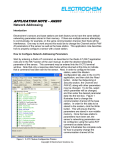
October 14, 2010 Dr. Andrew Rawicz School of Engineering Science Simon Fraser University Burnaby, British Columbia V5A 1S6 Re: ENSC 440 Functional Specification for an Automatic Parking Enforcer system Dear Dr. Rawicz: Attached is a document from Park Inc. describing the functional specification for the Automatic Parking Enforcer (APE) system. This document outlines the various requirements that need to be met for a successful product. APE is a product that captures the license plate image with the use of an infrared camera and converts the image to a series of letters and numbers. The Letters and numbers of each license plate are then matched with an existing database to determine whether the parked vehicle has permission to park in that particular parking lot. This document is designed to provide a higher level understanding of the requirements needed for the system. Hence, the requirements written in this document will be used as a guide by our engineers during the proof of principle and development phase of the APE system. APE system is produced by Park Inc. which consists of five talented and dedicated members: Rodin Maroufi, Rosy Johal, Amin Moshgabadi, Yi-Chen Kuo, and Shadi Rohani. Please feel free to contact us with any questions or comments that you may have regarding this function specification by phone at 778.865.2444 or by e-mail at [email protected]. Thank you, for your time and consideration. Sincerely, Rodin Maroufi Rodin Maroufi President and CEO Park Inc. Enclosure: Functional Specification for an Automatic Parking System Copyright ©2010, Park Inc. Function Specification for the Automatic Parking Enforcer System Project Team: Rodin Maroufi Rosy Johal Amin Moshgabadi Yi Chen Kuo Shadi Rohani Contact Person: Rodin Maroufi rma12 @sfu.ca Submitted to: Dr. Andrew Rawics Michael Sjoerdsma School of EngineeringScience Simon Fraser University Issued Date: October 14, 2010 Revision: 1.3 Copyright ©2010, Park Inc. Executive Summary Patrolling parking lots, particularly in big Campuses, can be very time consuming and requires many workers. The traditional method of parking officials manually checking every permit in the parking lot can be quite inconvenient for the drivers because people often interchange their cars and might forget to take their parking permit with them. Hence, APE is an automated system that will allow just one campus patrol officer to quickly patrol the parking lot in a car and determine which cars are authorized to be there. This will eliminate a significant amount of cost overhead for the campus, because less people will be needed, and the need to print parking permits will be eliminated. The automated system will also be more convenient for the drivers, as they will be able to interchange cars and not worry about forgetting their parking permit. The APE system will compare the images taken from a moving vehicle to a database for vehicles with permits to determine which vehicles are authorized to be in the parking lot. The implementation of this system will be split into four parts: license plate segmentation, optical character reorganization (OCR), graphical user interface (GUI), and integration of all parts. Once the system is fully implemented, tests will be carried out to verify the functionality and usability of the APE system. We will also follow a tentative schedule of when each of the parts will be complete and will have the prototype finished by December 6, 2010. Additionally, the total cost of making the prototype was determined to be $760 and the sale price of the whole unit will be $2000. The price was determined to be $2000 because the product is very specialized hence a higher price needs to be set to obtain a reasonable profit margin. Copyright ©2010, Park Inc. ii Table of Contents Executive Summary .................................................................................................................... ii Revision History ......................................................................................................................... iv Glossary..................................................................................................................................... iv 1. Introduction ......................................................................................................................... 1 1.1 Scope............................................................................................................................ 1 1.2 Intended Audience ........................................................................................................ 1 1.3 Classification ................................................................................................................. 1 2. System Requirements ......................................................................................................... 2 2.1 System Overview .......................................................................................................... 2 2.2 General Requirements .................................................................................................. 3 2.3 Physical Requirements.................................................................................................. 3 2.4 Enviromental Requirements…………………………………………………………………...3 2.5 Electrical Requirements ................................................................................................ 3 2.6 Mechanical Requirements ............................................................................................. 3 2.7 LPR Software Requirements ......................................................................................... 4 2.8 Performance Requirements .......................................................................................... 4 2.9 User Manual Requirements ........................................................................................... 4 2.10 Usability Requirements ............................................................................................... 4 2.11 Standard Requirements .............................................................................................. 5 2.12 Reliability and Durability .............................................................................................. 5 2.13 Safety Requirements ................................................................................................... 5 3. System Test Plan……………………………………………………………………………. ……..6 4. Conclusion……………………………………………………………………………………….…..7 Copyright ©2010, Park Inc. iii Revision History Version 1.0 1.1 1.2 1.3 Date 26 / 09 / 2010 10 / 10 / 2010 12 / 10 / 2010 14 / 10 / 2010 Task Rough template created Rough copy completed Editing completed Accepted by all team members Glossary OCR Optical Character Reorganization GUI Graphical User Interface CSA Canadian Standards Association ASCII American Standard Code for Information Interchange SSL Secure Socket Layer PFSA Parking Federation Standard Association Copyright ©2010, Park Inc. iv 1. Introduction The APE system from Park Inc. consists of an infrared camera, and a software program with a graphical user interface. The infrared Camera will be mounted on a patrolling officer’s vehicle and will be responsible for retrieving the license plate from the parked vehicle. An infrared camera can be used for this purpose because once light is applied to the vehicle the reflective material used in the production of the license plate will distinguish it from other parts of the vehicle. The retrieved license plate is than compared to a database, which will consist of license plate numbers of the drivers with parking permits. In accordance, with our product the driver can register more than one license plate number under their permit. Our software will make sure that there are not multiple vehicles under one permit in the parking lot simultaneously. 1.1 Scope This document illustrates the functional requirements that will be met by a successful APE system. Hence, the requirements listed in this document will describe in full by the proof- ofprinciple and some parts of the production of the APE system. Furthermore, this document will serve as an important reference to the Park Inc. team during the implantation and development of the APE system. 1.2 Intended Audience This document is intended for the whole Park Inc. team, who shall refer to it at various stages of the design process. The CEO will refer to the document to monitor the progress of the prototype. The engineers will use the document to ensure that the product meets the CSA standards as well as other requirements. The engineers will also use this document to verify that the final prototype functions according to the requirements proposed here. 1.3 Classification To denote the functional requirement the following standard shall be utilized: [Rn-x] A function requirement. where the functional requirement number is represented by n, and the priority of the functional requirement is represented by x. Additionally, x is segregated into the following three categories: I II III Functional requirement for first prototype only. Functional requirement for first prototype and final product. Functional requirement for final product only. 1 2. System Requirements All the requirements of the final product are listed below. We expect to meet all the following requirements to successfully implement our product. 2.1 System Overview Figure 2.1 represents the basic concept of the APE system, which consists of both hardware and software components. The hardware component of the APE system consists of: an infrared camera, an image processor, a communication channel, and a data storage unit. The software component of the APE system consists of: license plate segmentation, optical letter reorganization, and a GUI. Figure 2.1: System Overview of APE. An infrared camera will be responsible for taking a clear picture and the image processing unit will be responsible for localizing the license plate from that image. If no license plate is detected in the current image, the software moves to the next image. Once, a license plate is detected the image is then checked to see if it is clear enough to be used by the OCR engine. Once, a clear image is obtained then the OCR engine is used to implement letter segmentation and output ASCII characters, which make up the license plate number. The output of the OCR will then be compared to a database of registered vehicles. The result of the comparison will then be published by the GUI. 2 2.2 General Requirements [ R1 – II ] [ R2 – III ] [ R3 – II ] [ R4 – II ] [ R5 – III ] [ R6 – II ] Speed of motor vehicle must not be more than 30 km/hr, so that the camera would be able to read the license plate. The vehicle must have a valid British Columbia license plate. Camera should operate in rain, fog, snow and darkness. Camera must be zoomed to include the vehicles of all sizes. Final product with all the accessories must be priced below $2000 CAD. System must know where the security vehicle is located so it can compare with right data base. 2.3 Physical Requirements [ R7 – III ] [ R8 – II ] [ R9 – III ] The camera stand should be able to rotate in all directions. Distance between the security vehicle and parked cars should be in the correct range so the camera can read the plates. Camera must be water proof for protection purposes. 2.4 Environmental Requirements [ R10 – III ] [ R11 – III ] [ R12 – III ] [ R13 – III ] Camera should operate in all weather conditions. Camera or the case should not be sensitive to temperature. Camera must not be sensitive to dust, fog and rust. The unit must be operational under dark lightening, since it should fully operate for indoor parking lots. 2.5 Electrical Requirements [ R14 – III ] [ R15 – III ] [ R16 – III ] All the electrical equipment has to be able to run on a regular car battery. The camera and laptop that is used to do the image processing is powered by the car’s internal battery. The battery has to be powerful enough to support the laptop. Both the camera and laptop must be able to be turned off or go to sleep mode to save power when not in use 2.6 Mechanical Requirements [ R17 – III ] The camera must have a simple locking mechanism with the car to prevent theft. 3 2.7 LPR Software Requirements [ R18 – II ] [ R19 – II ] [ R20 – II ] [ R21 – III ] The software must be able to correctly localize the license plate region with only marginal error. The OCR engine must be able to convert the image to ASCII characters at least 95% of the time. The processing power should be fast enough so there are no missed vehicles. Operating system of the laptop must be minimum windows XP. 2.8 Performance Requirements [ R22 – II ] [ R23 – II ] [ R24 – III ] [ R25 – III ] [ R26 – III ] The laptop must be able to compare the license plate number to the data base in real time. The image taken by the camera must not have any noise or be blurred. The camera must be able to work in all conditions such as night time or foggy weather. The camera must be able to take pictures at a high rate thus accommodating a fast moving vehicle. The whole process must not take more than one second so there are no cars missed. 2.9 User Manual Requirements [ R27 – III ] [ R28 – III ] [ R29 – III ] [ R30 – III ] [ R31 – III ] User manual should be written in a manner that an audience without any engineering knowledge can understand this material. There should be a separate documentation for technicians who want to install the product. In user documentation a website and email address must be mentioned for customer service and technical questions. User documentation will be in English. If the product goes on sale internationally the manual will be translated. 2.10 Usability Requirements [ R32 – II ] [ R33 – II ] [ R34 – II ] [ R35 – II ] [ R36 – II ] [ R37 – II ] [ R38 – II ] [ R39 – II ] Different users can log into the system with a valid user id and password. Different users can also log out of the system at any time. Allows the user to switch between parking lots at any time. Will display the initial image taken by the camera in one section. Will display the part of the database in another section. Will display real time video in a different section. Will display a check mark if the license plate compared is in the database. Will display invalid sign if license plate compared is not in the database. 4 [ R40 – II ] [ R41 – II ] [ R42 – II ] [ R43 – II ] [ R44 – II ] [ R45 – II ] [ R46 – II ] [ R47 – II ] Will display the ASCII characters outputted by the OCR. Allow the user to manually insert the license plate to be compared if image can’t be taken. Will contain a button to back go to the previous layer. Will contain a layer for user to login with id and password. Will contain a map of all the different SFU parking lots in one layer. The map will be comprised of dynamic buttons which when pressed will load the database of that parking lot. The system will also show the date and time. The system will show a warning message if log off is pressed. 2.11 Standard Requirements [ R48 – II ] [ R49 – II ] The APE system should be able to meet the PFSA. The server in which the database is stored must have a SSL or similar product securing it 2.12 Reliability and Durability [ R50 – III ] [ R51 – III ] [ R52 – III ] [ R53 – II ] [ R54 – II ] Any kind of weather condition will not affect the performance of the system. The exposed hardware parts are water proof and fully functional in hot, rainy and foggy conditions. The camera must take video for as long as it is not turned off manually. The system must run and compare the license plates with data base until the stop button is hit by the user or a desired match is found. Data base should be always available to the user. 2.13 Safety Requirements [ R55 – III ] [ R56 – III ] [ R57 – III ] [ R58 – II ] The driver should be notified by a sound if the parked car does not have the proper license, so the driver can focus on the road and does not get distracted. The system should let the driver know if it fails to read a license plate properly. The camera must be installed so that it does not stick out of the side of the vehicle too much to avoid collision. The system should let the driver know if it cannot access the database, or if the database is out of date. 5 3. System Test Plan To successfully implement the requirements stated in this document, the product will be tested during and after each stage of the design process. The first step in the testing process includes the camera which will go through initial testing to see whether the motor is fast enough to continuously take pictures while the security vehicle travels at a fast speed. Hence, a test plan for the camera is to mount it on a vehicle and drive the vehicle at an appropriate speed in the parking lot. If the camera takes clear images with a one second difference between each image then the camera will pass the test. The second step in the test plan is to test the connection between the camera and the image processor. The third step in the test plan is to test the License Plate Segmentation code, which will incorporate unit tests, functional tests and integration tests. The unit tests will be performed to ensure that each part of the code operates properly and independently. The functional tests will be performed after all the unit tests are passed. Functional tests will be used to verify that all the individual processes function correctly. Once, all the functional tests are passed then integration tests will be performed to ensure that all the code functions and communicates correctly. Therefore, if the program successfully crops the license plate from the remaining image then the Letter segmentation testing will be considered a success. The forth step in the test plan is to test the OCR engine by comparing the actual license plate number to the ASCII characters outputted by the OCR. If the two are the same then the OCR will be confirmed to function properly. The fifth step of the test plan involves testing the connection between the user interface and database, if a connection is established then the test will be successful. The sixth step in the test plan involves verifying specific requirements of the GUI, such as security features and real-time communication between two or more computers. The security features can be tested by verifying that only employee’s with valid passwords and id’s can access the database. Furthermore, each password will require at least 7 characters which include numbers and letters. Additionally, the security of the database will also be tested to verify that unauthorized access and to secure SFU drivers’ information will not occur. The seventh step in the testing process is to test the usability of the GUI. This will be accomplished by setting up test groups to ensure that the GUI is user friendly. Vis-a-vis, the layout is well-constructed, all notify messages are clear and informative, and buttons are properly functioned. The final step in the testing plan is final release testing, which is utilized to identify any minor issues that need to be addressed in order to present an error free product. 6 4. Conclusion This document describes the functional, operational and safety requirements which need to be met if a successful APE system is to be produced. We are currently in the process of designing, testing and implementing the prototype, which shall meet all the requirements listed in this document. The target date for the prototype completion is December 6, 2010. 7