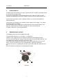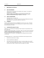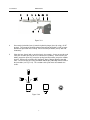
1
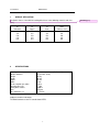
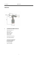
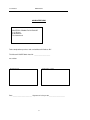
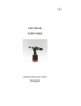
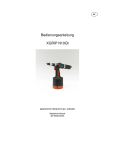
GB
User Manual
XGRIP R64S
MASTERFIX PRODUCTS BV EUROPE
Maastricht-Airport
The Netherlands
User Manual
XGRIP R64S
CONTENTS OF USER MANUAL R64S
1
Area of application
2
Specifications and dimensions
3
Standard equipment
4
Safety instructions
5
Initial start-up
6
Description of the R64S
6.1
6.2
7
Operation
Nose replacement
Maintenance
7.1
7.2
7.3
7.4
7.5
Daily maintenance
Weekly maintenance
Overhaul
Cleaning/replacing the jaws
Adding oil
8
Parts list with general arrangement
9
Guarantee and service
Guarantee form
2
User Manual
1
XGRIP R64S
AREA OF APPLICATION
The R64S riveter is intended for installing blind rivets in the following materials and sizes
[mm]:
Al
aluminium
4,0
4,8
5,0
6,0
6,4
2
Cu
copper
4,0
4,8
5,0
6,0
6,4
St
steel
4,0
4,8
5,0
6,0
6,4
St/St
stainless steel
4,0
4,8
5,0
6,0
6,4
SPECIFICATIONS
Capacity
Mandrel diameter
Weight
Length
Height
Stroke
Air consumption per stroke
Operating pressure
Pulling force at 6 bar
Jaws
Nose holder dia. x L
From 4.0 to 6.4 mm
Max. 4.0 mm (5/32”)
2,45 kg
299 mm
285 mm
22 mm
2,1 litres
5 - 7 bar
14.000 N
three-part
23 x 76 mm
Subject to technical alterations.
The R64S conforms to the EC standard 98/37 EEC.
3
(5/32” to 1/4”)
Opmerking [*1]:
User Manual
XGRIP R64S
DIMENSIONS
3
STANDARD EQUIPMENT FOR R64S
-
Four nose pieces, i.e.:
4.0 mm (5/32”)
4.8/5.0 mm (3/16”)
6,0 mm (0.236”)
6,4 mm (1/4”)
-
One key for nose pieces
-
One mandrel container
-
One oil refill kit comprising:
one bottle of hydraulic oil
one 3 mm Allen key
one filling syringe
-
One user manual
4
User Manual
4
XGRIP R64S
SAFETY INSTRUCTIONS
Anyone who operates or maintains the R64S riveter must first read this User Manual
carefully, paying extra attention to the instructions below.
Never dismantle the tool without first having thoroughly studied the instructions given in this
User Manual and applying them.
-
-
-
Always use the tool in accordance with the specified safety instructions.
Direct any queries regarding optimal and safe operation or use of the tool to
Masterfix Products.
The safety instructions must be made clear to all persons involved.
Never connect the tool to any medium other than compressed air.
Hold the air hose firmly when disengaging to prevent it from hurtling to and fro due to
the escaping air.
Use the tool only for the installation of blind rivets. The tool must never be used for
giving blows or impacting or as a hammer.
Do not make any modification(s)/change(s). Any modifications to the tool or
(supplied) parts and their consequences are completely outside the liability of
Masterfix Products and are entirely the liability of the operator; any guarantee claim
shall then be null and void.
Masterfix Products is always prepared to advise you with regard to different
applications.
The tool must be constantly maintained and examined/inspected at regular intervals.
Maintenance shall be performed by staff trained for that purpose. Do not perform
any maintenance before reading this User Manual.
Do not hesitate to contact Masterfix Products if you require training.
Always shut off the air supply before emptying the collector bowl or replacing the
nose piece.
Always disconnect the tool from the air supply before carrying out repairs or
maintenance. Disconnect the tool in case of failure before investigating the reason.
Never aim the tool at any person or object other than the material to be riveted.
Adopt a stable position and location before operating the tool.
The air discharge openings (at the bottom and collecting cup) must never be covered
or blocked. Ensure that air hoses are in good condition and can withstand a
minimum compressed air pressure of 10 bar.
Never exceed the maximum air pressure of 7 bar.
Always wear eye protection when using the riveter. Eye protection must be worn not
only by the user but also by everyone at the working place.
Never use the tool without (or with a defective) collector bowl.
Prevent excessive contact with hydraulic oil which could produce a rash.
To prevent accidental operation the trigger must never be touched when the tool is
being relocated.
Ensure that loose garments, ties, long hair, rags, etc. can not be caught by the
moving parts of the tool.
There could be a possibility that the mandrel comes out at the front side.
Please take account of that.
Hearing protection is advised.
5
User Manual
5
XGRIP R64S
INITIAL START-UP
The tool must be connected to an air filter-/separator unit; this unit filters the compressed air
to separate dirt and condensation.
A pressure regulator with a preferred setting of 6 bar (min. 5 bar, max. 7 bar) must be
installed if the operating pressure of the compressed air exceeds (or might exceed) 7 bar.
Use dry and clean materials (hoses, couplings, fittings, etc.) to connect the tool to the
filter/separator unit.
Check whether any leakage occurs anywhere in the compressed air supply. If so, replace
the damaged hoses or coupling.
Check the compressed air supply pressure to the tool; this must not exceed max. 7 bar.
Drain the condensation from the filter/separator unit. Also check the dirt filter.
The tool is ready for use, please do not add oil.
6
DESCRIPTION OF THE R64S
The following can be found at the bottom of the tool:
The replaceable nose pieces, 3 each (item 1, see figure 6.1).
Compressed air supply hose (0.5 m length, 6 mm ID), with union coupling (item 52).
Pressure relief valve (item 51) acting as safety valve to prevent overloading of the tool. The
valve opens if the compressed air pressure exceeds 7 bar.
It is possible to fit the supply hose to the other side (at the location of the pressure relief
valve). The pressure relief valve is then relocated to the supply hose connection.
Vacuum valve (item 57) controlling the extraction system of the tool to be switched on and
off.
Oil level indicator (item 50, figure 6.1) displaying oil shortage.
Figure 6.1
6
User Manual
6.1
XGRIP R64S
OPERATION
Ensure that the tool is fitted with the correct nose piece. You have the correct nose piece if
the diameter of the rivet corresponds to the inscription on the fitted nose piece (see section
6.2, nose piece replacement). Connect the tool to the compressed air supply using a quickaction coupling.
The mandrel container must be fixed on the tool.
The R64S is provided with an extraction system for automatically removing the broken
mandrel after the rivet is installed. A switch at the bottom ensures that the extraction system
is stopped if the tool is placed on a flat surface. The extraction system is re-started when the
tool is lifted.
Take the tool in your hand and place the mandrel of the rivet in the hole of the nose piece.
Place the rivet in the material to be riveted. The extraction system ensures that the rivet is
retained. Ensure that the correct hole size is used (0.1 mm larger than the rivet diameter for
standard rivets); also ensure that rivets with the correct cgrip range are used.
The rivet will be fixed by operating the trigger. The broken mandrel is automatically removed
to the mandrel container by vacuum by releasing the trigger. The next rivet can now be
placed in the nose piece.
The mandrel container must be emptied when it is almost full.
Do not use the tool without the mandrel collector, in order to prevent the tool from getting
damaged.
6.2
NOSE PIECE REPLACEMENT
The tool must be disconnected from the compressed air supply when a nose piece is being
replaced.
Screw the required nose piece from the bottom of the tool.
You have the correct nose piece if the rivet diameter corresponds to the inscription
on the nose piece.
Screw the old nose piece out of the nose piece holder. Ensure that the nose piece is
not ejected by the spring load.
Screw the new nose piece into the nose piece holder.
Screw the old nose piece into the bottom of the tool.
7
User Manual
XGRIP R64S
7
MAINTENANCE OF THE R64S
7.1
DAILY MAINTENANCE
-
Check if there are any leakages in the compressed air supply. If so, replace the
damaged hoses or couplings.
Check the compressed air supply pressure to the tool; it may be max. 7 bar.
Drain the condensate from the filter/separator unit. Also check the dirt filter.
Check the collector bowl for damage. Replace it, if necessary.
7.2
WEEKLY MAINTENANCE
-
Cleaning the jaws (see section 7.4).
Checking the stroke. The stroke is too short if the oil level indicator pin (item 36) no
longer protrudes. Oil must then be added (see section 7.5).
7.3
OVERHAUL
Overhaul shall be performed after every 300,000 rivets or once every 3 years. The tool is
then completely dismantled and all seals and worn parts are replaced. Have the overhaul
performed by Masterfix Products.
7.4
CLEANING/REPLACING THE JAWS
If blind rivets are installed only after operating the tool a few times, the performance of the
jaws may be poor.
The jaws must be cleaned regularly - at least once a week. They must also be cleaned if the
mandrel is no longer gripped when operating the tool. The jaws must also be cleaned if the
tool has to be operated a few times to install the rivets.
The jaws are worn if the mandrel is still not gripped after cleaning and a new set of jaws
must be fitted.
The following procedure is used to change the conduit or to clean or to replace the jaws:
1
Disconnect the tool from the air supply.
2
Place the tool flat on the workbench.
3
Unscrew the nose piece holder (item 2, figure 7.4.1) from the body, using a 24 AF
spanner. Do not hit the trigger with the spanner. The nose piece (item 1) may be left
on the nose piece holder. Remove the nose piece holder in its entirety.
8
User Manual
XGRIP R64S
Figure 7.4.1
4
Unscrew the jaw holder (item 3) from the hydraulic plunger (item 19) using a 15 AF
spanner. To prevent the hydraulic plunger from turning hold it with a 12 AF spanner.
Remove the jaw holder in its entirety. Ensure that the jaw holder (item 3) does not
shoot away.
5
Clean the jaws (item 4) with a steel wire brush, for example. A new set must be used
if the jaws are worn (this may be assessed from the serrations). Also clean the jaw
holder, jaw pusher (item 5a), jaw pusher spring (item 5b) and the jaw pusher conduit
(item 5). Replace the relevant part if damaged. Apply a drop of oil to the rounded
sides. Then insert the jaws in the jaw holder with the tips protruding from the front of
the jaw holder (see Fig. 7.4.2). The serrations of the jaws must face towards the
centre.
Figure 7.4.2
9
User Manual
6
XGRIP R64S
In order to take out or replace the conduit from the hydraulic plunger, proceed as
follows:
Take the collector bowl from the tool, press the stop-valve of the extraction and push
carefully with a pen or with the delivered accessory the conduit out of the plunger
through the back side of the tool.
7
In case of damaged parts, replace the part concerned.
8
Fit the jaw holder to the hydraulic plunger and tighten it with the 15 AF spanner.
Once again, you must retain the hydraulic plunger with the 12 AF spanner.
9
Check whether the nose piece holder and the nose piece are clean. Clean them, if
necessary.
Fit the nose piece holder to the body. Remember the O-ring (item 7).
do not damage it when fitting the nose piece holder
fit a new one if it is already damaged
if the O-ring is dry, please use grease
clean the O-ring if it is dirty.
Tighten the nose piece holder with the 24 AF spanner. Do not hit the trigger with the
spanner.
10
User Manual
7.5
XGRIP R64S
ADDING OIL
There may be insufficient oil in the tool if blind rivets are installed only after operating the tool
a few times.
Oil shortage in the tool leads to reduction of the stroke. The oil level indicator (item 50, see
chapter 8) shows whether loss of oil has occurred. The tool has lost oil if the oil level
indicator pin no longer protrudes. Proceed as follows to add oil:
1
Keep the tool upright during all operations.
Disconnect the tool from the air supply.
2
Unscrew the M4 cap screw (item15, see chapter 8) from the body using the size 3
mm Allen key. Make sure the O-ring (item 14) remains in the hole.
3
Fill the (supplied) syringe with hydraulic oil (a bottle is also supplied with the tool).
4
Screw the filled syringe up to the O-ring in the hole. Then slowly inject the oil into the
tool (ensure no air is injected). Adequate oil has been added as soon as resistance
is sensed. The check catch of the oil level indicator is then visible again. The tool
now has its optimal stroke (22 mm) again.
The excess oil will flow back when the syringe is released if too much oil has been
added.
5
Unscrew and remove the syringe from the body. Check whether the O-ring remains
in the hole.
6
Screw the M4 cap screw into the hole using the size 3 mm Allen key.
7
Wipe off the excess oil.
11
User Manual
8
XGRIP R64S
PARTS LIST
Item No.
1
1
1
1
2
3
4
5
5a
5b
6
7
8
9
10
11
12
13
14
15
16
17
18
19
20
21
22
23
24
25
26
27
28
29
30
31
32
33
34
35
36
37
38
39
40
41
42
43
44
45
46
Qty
1
1
1
1
1
1
1 set
1
1
1
2
1
1
1
1
1
1
1
1
1
1
1
1
1
1
1
1
1
1
1
1
1
1
1
1
2
1
1
1
1
1
1
1
1
1
1
1
1
1
3
1
Description
nose-piece 4.0 mm (5/32")
nose-piece 4.8/5.0 (3/16" - 0.196")
nose-piece 6.0 mm (0.236")
nose-piece 6.4 mm (1/4")
front sleeve
clamping sleeve
clamping jaws (3 parts)
conduit 5
jaw pusher
jaw pusher spring
o-ring 6,5/1,6
o-ring 14.3/2.4, hydraulic plunger rod
o-ring 20/1, front sleeve
lip seal 13/8-4
ring for compression spring
o-ring 18/2.2, hydraulic plunger rod
lip seal 18 x 25, hydraulic plunger rod
buffer ring, hydraulic plunger
o-ring 4/1.5
cap screw M4 x 8
hanger
lip seal 34 x 22 x 9.4, hydraulic piston
guide ring
hydraulic plunger
hydraulic body
compression spring Ø 14 mm
compression spring Ø 24 mm
rear screwed joint
lip seal 13/8-4
o-ring 44/3
spring
valve
mandrel container
extension
Pin cylindrical 3,0 x 11
cap screw M4 x 8
lip seal 22/16-6, pneumatic plunger rod
guide ring
o-ring 16/2
bottom ring
top ring
pneumatic plunger
tube
ring for compression spring
safety ring 6
case
o-ring 8/2
Teflon ring
ring
o-ring 10/2, pneumatic plunger
o-ring 89/4, pneumatic plunger
12
User Manual
47
48
49
50
51
52
53
54
55
56
57
58
59
60
61
62
63
64
65
66
67
68
69
XGRIP R64S
1
1
1
1
1
1
2
2
2
1
1
1
1
2
3
1
3
1
1
1
1
1
1
1
1
1
1
o-ring 94/1,5
bottom
o-ring 10/1.5
oil level indicator
pressure relief valve
union coupling 90°
connecting bolt
copper washer for connecting bolt
M6 cap nut for connecting bolt
bottom ring
valve complete
o-ring 4/1,5, valve pin
muffler hood
muffler
o-ring 4/2, valve pin
valve pin
Adjusting ring
diameter 14
o-ring 10/2
eccentric trigger
Pin cylindrical 3,0 x 20
trigger
o-ring 4/1, valve pin
oil syringe
bottle with oil, 30 cc
key for nose pieces
size 3 mm Allen key
return spring
13
User Manual
9
XGRIP R64S
GUARANTEE AND SERVICE
The user will not be able claim under guarantee if he does not observe the instructions
specified in this User Manual.
A guarantee period of 6 months applies, starting from the date of purchase.
The liability of Masterfix Products for this riveter and/or any of its defective parts shall be
limited to their replacement, the changing of worn parts (like jaws, sealings etc.) are
excluded. In no case shall the liability exceed the invoiced value of the supplied items.
Masterfix Products shall not be liable under any circumstances for damage or costs
occurring due to inexpert use of the tool and repair or replacement of parts performed by
anyone other than Masterfix Products itself.
To be able to make any guarantee claim, the guarantee form must be completed and sent to
Masterfix Products (see last page of the User Manual for guarantee form).
Maintenance shall be performed in accordance with the instructions solely by technical
persons qualified for the purpose.
It is advisable to consult Masterfix Products for advice on repairs or to present the tool for
repair to Masterfix Products.
MASTERFIX PRODUCTS BV EUROPE
P.O. Box 21
6190 AA Beek
Europalaan 12
6199 AB Maastricht-Airport
Tel:
Fax:
+31 (0)43 350 84 84
+31 (0)43 350 84 88
14
User Manual
XGRIP R64S
GUARANTEE FORM
MASTERFIX PRODUCTS BV EUROPE
P.O. BOX 21
6190 AA Beek
The Netherlands
To be completed on purchase and send to Masterfix Products B.V.
This Masterfix XGRIP R64S riveter Nr. ____________________
was sold to:
Stamp/address vendor:
Stamp/address buyer:
Date ________________________ Signature of sales person____________________
15
User Manual
XGRIP R64S
EC-DECLARATION OF CONFORMITY FOR MACHINERY
We
MASTERFIX PRODUCTS BV EUROPE
Europalaan 12
6199 AB Maastricht-Airport
The Netherlands
herewith declare that the product
type:
application:
XGRIP R64S pneumatic-hydraulic riveter
blind rivets all materials 4.0 - 6.4 mm
which this declaration refers to,
is in conformity with the provisions of the regulations EC standard 98/37 EEC.
The Netherlands, Maastricht-Airport 29-08-2001
J.M.E.L. Aarts
16
User Manual
XGRIP R64S
WWW.MASTERFIX.COM
The Netherlands (Head Office)
Masterfix Products b.v.
Europalaan 12
6199 AB Maastricht Airport
Tel. +31-43-350 84 84
Fax +31-43-350 84 88
E-Mail: [email protected]
Germany
Europalaan 12
6199 AB Maastricht Airport
Tel. +31-43-350 84 84
Fax +31-43-350 84 88
E-Mail: [email protected]
Polen
Masterfix Poland
ul. Daleka 16
60-124 Poznan
Poland
Tel. +48-61-86 66 297/ 376
Fax +48-61-86 65 733
E-Mail: [email protected]
United Kingdom
Masterfix Products UK Ltd.
Units 4a,b& d, Ring Road
Zone 2, Burntwood Business Park
Burntwood
Staffordshire WS7 3JQ
Great Britain
Tel. +44-1543-686 989
Fax +44-1543-675 822
E-Mail: [email protected]
Spain
Black & Decker Ibérica, S.C.A
Business Unit Masterfix
Ctra. M-300, Km 29,700
28802 Alcalá de Henares
Madrid, España
Teléfono +34-91-883 57 30
Fax +34-91-880 87 20
E-mail: [email protected]
17