1
2.0 - 2.1 Connecting Inputs & Outputs
Nucleus Plus™ has been designed so that ONLY the correct hardware can
be plugged into the appropriate input or output. The following is a guideline
on how hardware should be connected in order to prevent damage to Nucle2.0 Connecting Inputs
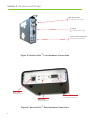
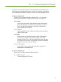
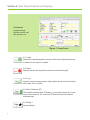
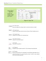
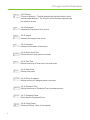
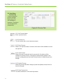
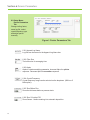
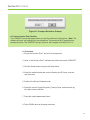
There are four (4) inputs attached to Nucleus Plus™. It is important
that the correct hardware is used with these inputs (see Figure E).
2.0.1 Power
Only the provided power supply should be used with Nucleus
Plus™. Not doing so will cause hardware damage to Nucleus
Plus™ that will not be covered by warranty. Ensure that the
power supply has a 24 [VDC].
2.0.2 Comport
Connect an RS232 cable to this port. Always use the provided
USB to RS232 cable.
2.0.3 BNC
Nucleus Plus™ has a built in oscillator. (Phillip Technologies
also offers an external oscillator for purchase). The cable
between Nucleus Plus™ and the crystal should remain as short
as possible to avoid noise. The advisable maximum acceptable
length for this is one (1) foot or 30 [cm].
2.0.4 TC Connection
Nucleus Plus™ uses a thermocouple probe to measure the
temperature of the sensor head.
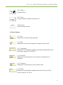
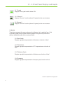
2.1 Connecting Output
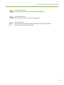
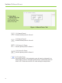
There is one (1) output attached to Nucleus Plus™.
2.1.1 DB9 Connector
Connects the two SPST relays.
4