1
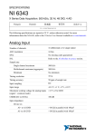
DAQ
BNC-2140 User Manual
Dynamic Signal Acquisition Signal Conditioning Accessory
BNC-2140 User Manual
June 2003 Edition
Part Number 321933D-01
Support
Worldwide Technical Support and Product Information
ni.com
National Instruments Corporate Headquarters
11500 North Mopac Expressway
Austin, Texas 78759-3504
USA Tel: 512 683 0100
Worldwide Offices
Australia 1800 300 800, Austria 43 0 662 45 79 90 0, Belgium 32 0 2 757 00 20, Brazil 55 11 3262 3599,
Canada (Calgary) 403 274 9391, Canada (Montreal) 514 288 5722, Canada (Ottawa) 613 233 5949,
Canada (Québec) 514 694 8521, Canada (Toronto) 905 785 0085, Canada (Vancouver) 514 685 7530,
China 86 21 6555 7838, Czech Republic 420 2 2423 5774, Denmark 45 45 76 26 00,
Finland 385 0 9 725 725 11, France 33 0 1 48 14 24 24, Germany 49 0 89 741 31 30, Greece 30 2 10 42 96 427,
India 91 80 51190000, Israel 972 0 3 6393737, Italy 39 02 413091, Japan 81 3 5472 2970,
Korea 82 02 3451 3400, Malaysia 603 9131 0918, Mexico 001 800 010 0793, Netherlands 31 0 348 433 466,
New Zealand 1800 300 800, Norway 47 0 66 90 76 60, Poland 48 0 22 3390 150, Portugal 351 210 311 210,
Russia 7 095 238 7139, Singapore 65 6226 5886, Slovenia 386 3 425 4200, South Africa 27 0 11 805 8197,
Spain 34 91 640 0085, Sweden 46 0 8 587 895 00, Switzerland 41 56 200 51 51, Taiwan 886 2 2528 7227,
Thailand 662 992 7519, United Kingdom 44 0 1635 523545
For further support information, refer to the Technical Support and Professional Services appendix. To comment
on the documentation, send email to [email protected].
© 1998–2003 National Instruments Corporation. All rights reserved.
Important Information
Warranty
The BNC-2140 is warranted against defects in materials and workmanship for a period of one year from the date of shipment, as evidenced by
receipts or other documentation. National Instruments will, at its option, repair or replace equipment that proves to be defective during the
warranty period. This warranty includes parts and labor.
The media on which you receive National Instruments software are warranted not to fail to execute programming instructions, due to defects
in materials and workmanship, for a period of 90 days from date of shipment, as evidenced by receipts or other documentation. National
Instruments will, at its option, repair or replace software media that do not execute programming instructions if National Instruments receives
notice of such defects during the warranty period. National Instruments does not warrant that the operation of the software shall be
uninterrupted or error free.
A Return Material Authorization (RMA) number must be obtained from the factory and clearly marked on the outside of the package before
any equipment will be accepted for warranty work. National Instruments will pay the shipping costs of returning to the owner parts which are
covered by warranty.
National Instruments believes that the information in this document is accurate. The document has been carefully reviewed for technical
accuracy. In the event that technical or typographical errors exist, National Instruments reserves the right to make changes to subsequent
editions of this document without prior notice to holders of this edition. The reader should consult National Instruments if errors are suspected.
In no event shall National Instruments be liable for any damages arising out of or related to this document or the information contained in it.
EXCEPT AS SPECIFIED HEREIN, NATIONAL INSTRUMENTS MAKES NO WARRANTIES, EXPRESS OR IMPLIED, AND SPECIFICALLY DISCLAIMS ANY WARRANTY OF
MERCHANTABILITY OR FITNESS FOR A PARTICULAR PURPOSE. CUSTOMER’S RIGHT TO RECOVER DAMAGES CAUSED BY FAULT OR NEGLIGENCE ON THE PART OF
NATIONAL INSTRUMENTS SHALL BE LIMITED TO THE AMOUNT THERETOFORE PAID BY THE CUSTOMER. NATIONAL INSTRUMENTS WILL NOT BE LIABLE FOR
DAMAGES RESULTING FROM LOSS OF DATA, PROFITS, USE OF PRODUCTS, OR INCIDENTAL OR CONSEQUENTIAL DAMAGES, EVEN IF ADVISED OF THE POSSIBILITY
THEREOF. This limitation of the liability of National Instruments will apply regardless of the form of action, whether in contract or tort, including
negligence. Any action against National Instruments must be brought within one year after the cause of action accrues. National Instruments
shall not be liable for any delay in performance due to causes beyond its reasonable control. The warranty provided herein does not cover
damages, defects, malfunctions, or service failures caused by owner’s failure to follow the National Instruments installation, operation, or
maintenance instructions; owner’s modification of the product; owner’s abuse, misuse, or negligent acts; and power failure or surges, fire,
flood, accident, actions of third parties, or other events outside reasonable control.
Copyright
Under the copyright laws, this publication may not be reproduced or transmitted in any form, electronic or mechanical, including photocopying,
recording, storing in an information retrieval system, or translating, in whole or in part, without the prior written consent of National
Instruments Corporation.
Trademarks
National Instruments™, NI™, and ni.com™ are trademarks of National Instruments Corporation.
Patents
For patents covering National Instruments products, refer to the appropriate location: Help»Patents in your software, the patents.txt file
on your CD, or ni.com/patents.
WARNING REGARDING USE OF NATIONAL INSTRUMENTS PRODUCTS
(1) NATIONAL INSTRUMENTS PRODUCTS ARE NOT DESIGNED WITH COMPONENTS AND TESTING FOR A LEVEL OF
RELIABILITY SUITABLE FOR USE IN OR IN CONNECTION WITH SURGICAL IMPLANTS OR AS CRITICAL COMPONENTS IN
ANY LIFE SUPPORT SYSTEMS WHOSE FAILURE TO PERFORM CAN REASONABLY BE EXPECTED TO CAUSE SIGNIFICANT
INJURY TO A HUMAN.
(2) IN ANY APPLICATION, INCLUDING THE ABOVE, RELIABILITY OF OPERATION OF THE SOFTWARE PRODUCTS CAN BE
IMPAIRED BY ADVERSE FACTORS, INCLUDING BUT NOT LIMITED TO FLUCTUATIONS IN ELECTRICAL POWER SUPPLY,
COMPUTER HARDWARE MALFUNCTIONS, COMPUTER OPERATING SYSTEM SOFTWARE FITNESS, FITNESS OF COMPILERS
AND DEVELOPMENT SOFTWARE USED TO DEVELOP AN APPLICATION, INSTALLATION ERRORS, SOFTWARE AND
HARDWARE COMPATIBILITY PROBLEMS, MALFUNCTIONS OR FAILURES OF ELECTRONIC MONITORING OR CONTROL
DEVICES, TRANSIENT FAILURES OF ELECTRONIC SYSTEMS (HARDWARE AND/OR SOFTWARE), UNANTICIPATED USES OR
MISUSES, OR ERRORS ON THE PART OF THE USER OR APPLICATIONS DESIGNER (ADVERSE FACTORS SUCH AS THESE ARE
HEREAFTER COLLECTIVELY TERMED “SYSTEM FAILURES”). ANY APPLICATION WHERE A SYSTEM FAILURE WOULD
CREATE A RISK OF HARM TO PROPERTY OR PERSONS (INCLUDING THE RISK OF BODILY INJURY AND DEATH) SHOULD
NOT BE RELIANT SOLELY UPON ONE FORM OF ELECTRONIC SYSTEM DUE TO THE RISK OF SYSTEM FAILURE. TO AVOID
DAMAGE, INJURY, OR DEATH, THE USER OR APPLICATION DESIGNER MUST TAKE REASONABLY PRUDENT STEPS TO
PROTECT AGAINST SYSTEM FAILURES, INCLUDING BUT NOT LIMITED TO BACK-UP OR SHUT DOWN MECHANISMS.
BECAUSE EACH END-USER SYSTEM IS CUSTOMIZED AND DIFFERS FROM NATIONAL INSTRUMENTS' TESTING
PLATFORMS AND BECAUSE A USER OR APPLICATION DESIGNER MAY USE NATIONAL INSTRUMENTS PRODUCTS IN
COMBINATION WITH OTHER PRODUCTS IN A MANNER NOT EVALUATED OR CONTEMPLATED BY NATIONAL
INSTRUMENTS, THE USER OR APPLICATION DESIGNER IS ULTIMATELY RESPONSIBLE FOR VERIFYING AND VALIDATING
THE SUITABILITY OF NATIONAL INSTRUMENTS PRODUCTS WHENEVER NATIONAL INSTRUMENTS PRODUCTS ARE
INCORPORATED IN A SYSTEM OR APPLICATION, INCLUDING, WITHOUT LIMITATION, THE APPROPRIATE DESIGN,
PROCESS AND SAFETY LEVEL OF SUCH SYSTEM OR APPLICATION.
Compliance
FCC/Canada Radio Frequency Interference Compliance
Determining FCC Class
The Federal Communications Commission (FCC) has rules to protect wireless communications from interference. The FCC
places digital electronics into two classes. These classes are known as Class A (for use in industrial-commercial locations only)
or Class B (for use in residential or commercial locations). All National Instruments (NI) products are FCC Class A products.
Depending on where it is operated, this Class A product could be subject to restrictions in the FCC rules. (In Canada, the
Department of Communications (DOC), of Industry Canada, regulates wireless interference in much the same way.) Digital
electronics emit weak signals during normal operation that can affect radio, television, or other wireless products.
All Class A products display a simple warning statement of one paragraph in length regarding interference and undesired
operation. The FCC rules have restrictions regarding the locations where FCC Class A products can be operated.
Consult the FCC Web site at www.fcc.gov for more information.
FCC/DOC Warnings
This equipment generates and uses radio frequency energy and, if not installed and used in strict accordance with the instructions
in this manual and the CE marking Declaration of Conformity*, may cause interference to radio and television reception.
Classification requirements are the same for the Federal Communications Commission (FCC) and the Canadian Department of
Communications (DOC).
Changes or modifications not expressly approved by NI could void the user’s authority to operate the equipment under the FCC
Rules.
Class A
Federal Communications Commission
This equipment has been tested and found to comply with the limits for a Class A digital device, pursuant to part 15 of the FCC
Rules. These limits are designed to provide reasonable protection against harmful interference when the equipment is operated
in a commercial environment. This equipment generates, uses, and can radiate radio frequency energy and, if not installed and
used in accordance with the instruction manual, may cause harmful interference to radio communications. Operation of this
equipment in a residential area is likely to cause harmful interference in which case the user is required to correct the interference
at their own expense.
Canadian Department of Communications
This Class A digital apparatus meets all requirements of the Canadian Interference-Causing Equipment Regulations.
Cet appareil numérique de la classe A respecte toutes les exigences du Règlement sur le matériel brouilleur du Canada.
Compliance to EU Directives
Readers in the European Union (EU) must refer to the manufacturer’s Declaration of Conformity (DoC) for information*
pertaining to the CE marking compliance scheme. The manufacturer includes a DoC for most hardware products except for those
bought from OEMs. In addition, DoCs are usually not provided if compliance is not required, for example electrically benign
apparatus or cables.
To obtain the DoC for this product, click Declarations of Conformity Information at ni.com/hardref.nsf/. This Web site
lists the DoCs by product family. Select the appropriate product family, followed by your product, and a link to the DoC appears
in Adobe Acrobat format. Click the Acrobat icon to download or read the DoC.
* The CE marking Declaration of Conformity contains important supplementary information and instructions for the user or
installer.
Contents
About This Manual
Conventions ...................................................................................................................vii
Related Documentation..................................................................................................vii
Chapter 1
Introduction
What You Need to Get Started ......................................................................................1-2
Unpacking ......................................................................................................................1-2
Optional Equipment .......................................................................................................1-3
Chapter 2
Installation and Configuration
Installation .....................................................................................................................2-1
Device Configuration.....................................................................................................2-1
Chapter 3
Signal Connections
I/O Connectors ...............................................................................................................3-1
Analog Input Signal Connections ..................................................................................3-5
Analog Output Signal Connections ...............................................................................3-5
Chapter 4
Theory of Operation
Functional Overview......................................................................................................4-1
Analog Input Circuitry...................................................................................................4-2
Analog Output................................................................................................................4-2
Appendix A
Specifications
Appendix B
Technical Support and Professional Services
© National Instruments Corporation
v
BNC-2140 User Manual
Contents
Glossary
Index
BNC-2140 User Manual
vi
ni.com
About This Manual
This manual describes the electrical and mechanical aspects of the
BNC-2140 accessory and contains information concerning its operation.
Conventions
The following conventions are used in this manual:
<>
Angle brackets containing numbers separated by an ellipsis represent a
range of values associated with a bit or signal name—for example,
P0.<3..0>.
This icon denotes a note, which alerts you to important information.
This icon denotes a caution, which advises you of precautions to take to
avoid injury, data loss, or a system crash.
bold
Bold text denotes items that you must select or click in the software, such
as menu items and dialog box options. Bold text also denotes parameter
names.
italic
Italic text denotes a variable, emphasis, a cross reference, or an introduction
to a key concept. This font also denotes text that is a placeholder for a word
or value that you must supply.
monospace
Text in this font denotes text or characters that you should enter from the
keyboard, sections of code, programming examples, and syntax examples.
This font is also used for the proper names of disk drives, paths, directories,
programs, subprograms, subroutines, device names, functions, operations,
variables, filenames and extensions, and code excerpts.
Related Documentation
The following documents contain information you may find helpful:
•
National Instruments Application Note 025, Field Wiring and Noise
Considerations for Analog Signals
•
NI 4551/4552 User Manual
•
PCI-4451/4452/4453/4454 User Manual
© National Instruments Corporation
vii
BNC-2140 User Manual
1
Introduction
This manual describes the electrical and mechanical aspects of the
BNC-2140 accessory and contains information concerning its operation.
This chapter describes the BNC-2140 accessory, lists what you need to get
started, explains how to unpack your BNC-2140, and describes optional
equipment.
The BNC-2140 is a signal conditioning accessory specifically designed for
use with a dynamic signal acquisition (DSA) device. It interfaces four BNC
signal inputs and two BNC signal outputs directly to National Instruments
DSA products including the NI PCI-4451, NI PCI-4452, NI PCI-4551, and
NI PCI-4552. The BNC-2140 connects to integrated circuit piezoelectric,
also known as Integral Electronic Piezoelectric (IEPE), accelerometers,
microphone preamplifiers, and other voltage sources with outputs of less
than ±42.4 V.
Each input channel has an independent 4 mA current source suitable for
use with IEPE-type accelerometers and microphone preamplifiers. You can
manually enable or disable the IEPE signal conditioning on a per-channel
basis. With IEPE disabled, a BNC-2140 input channel acts as a direct
voltage input. You can manually switch each input channel and each output
channel from differential (DIFF) to single-ended (SE) mode. In SE mode,
the BNC shell is connected to analog ground through a 50 Ω resistor.
The BNC-2140 receives power for IEPE signal conditioning from the DSA
plug-in device through the 68-pin high-density connector. A green LED
indicates when the IEPE circuitry is powered on. When IEPE signal
conditioning is not required, you can manually power off the circuits.
© National Instruments Corporation
1-1
BNC-2140 User Manual
Chapter 1
Introduction
What You Need to Get Started
To set up and use the BNC-2140 device, you need the following:
❑ BNC-2140
❑ One of the following DSA devices and its documentation:
–
NI PCI 4451
–
NI PCI 4452
–
NI PCI 4551
–
NI PCI 4552
❑ BNC-2140 User Manual
❑ Your computer
❑ SHC68-C68-A1 analog cable
For more information, refer to ni.com/appnotes.nsf for the National
Instruments Application Note 25, Field Wiring and Noise Considerations
for Analog Signals.
Unpacking
The BNC-2140 is shipped in an antistatic plastic package to prevent
electrostatic damage to the device. Several components on the device can
be damaged by electrostatic discharge.
Caution
Never touch the exposed pins of connectors.
To avoid damage in handling the device, take the following precautions:
•
Ground yourself with a grounding strap or by holding a grounded
object.
•
Touch the plastic package to a metal part of your computer chassis
before removing the device from the package.
•
Never touch exposed connector pins.
Remove the device from the package and inspect the device for loose
components or any other sign of damage. Notify National Instruments if the
device appears damaged in any way. Do not install a damaged device onto
your computer.
BNC-2140 User Manual
1-2
ni.com
Chapter 1
Introduction
Optional Equipment
If your application requires that you use transducers with microdot
connectors, use the BNC plug screw-on receptacle adapter, part number
033-0101-0001, from Microdot Connectors. This accessory allows you to
connect BNC and microdot connectors.
If your application requires that you use a prepolarized microphone with a
microphone preamplifier, contact Brüel and Kjær or go to bksv.com.
© National Instruments Corporation
1-3
BNC-2140 User Manual
Installation and Configuration
2
This chapter explains how to install and configure the BNC-2140.
Installation
You must power off the computer and install your National Instruments DSA device
before installing the BNC-2140. Refer to your DSA device documentation for instructions.
Note
Perform the following steps to install the BNC-2140:
1.
Insert either end of the SHC68-C68-A1 analog cable into the 68-pin
connector on the BNC-2140.
2.
Insert the other end into the 68-pin connector on the DSA plug-in
device.
3.
Tighten the jackscrews on both ends of the cable.
4.
Power on the computer.
The BNC-2140 accessory is now installed.
Device Configuration
You must manually configure the BNC-2140 accessory by setting the
channel switches. You can configure each input channel to enable or
disable IEPE signal conditioning and to take differential or single-ended
measurements. You also can configure each output channel for differential
or single-ended measurements. When IEPE signal conditioning is enabled,
large DC offset voltages can occur on signal inputs due to the output bias
voltage requirements of the IEPE transducer you are using. To remove this
offset, you must enable AC coupling on the affected input channels of the
DSA device. If you do not require IEPE signal conditioning, you can turn
the power off for the IEPE signal conditioning circuitry. Turning off the
IEPE power will disable IEPE excitation on all input channels. Refer to
Figure 2-1 for the location of the switches.
© National Instruments Corporation
2-1
BNC-2140 User Manual
Chapter 2
Installation and Configuration
You can connect or disconnect BNC cables carrying signals without powering off
the computer.
Note
IEPE POWER
Connector Accessory
AI 0
AI 2
AI 1
AI 3
IEPE POWER
IEPE POWER
IEPE POWER
IEPE POWER
AO 0
AO 1
Figure 2-1. Switch Settings and Signal Connections
BNC-2140 User Manual
2-2
ni.com
3
Signal Connections
This chapter describes how to connect input and output signals to
the BNC-2140.
You can connect external analog signals through six BNC connectors. Four
of the BNC connectors are for input signals and two are for output signals.
The SHC68-C68-A1 shielded cable connects the BNC-2140 internal
analog signal connector to the DSA plug-in device. A single 68-pin
0.8 mm VHDCI connector connects the analog I/O signals to the shielded
cable.
I/O Connectors
Table 3-1 describes the pin assignments for the six external I/O BNC
connectors.
Table 3-1. BNC Analog I/O Connector Signal Descriptions
Signal Name
Reference
Direction
Description
+AI <0..3>
AI GND
Input
+Analog Input Channel 0 through 3—Each channel
can have IEPE enabled or disabled. This signal
passes through the BNC internal conductor.
–AI <0..3>
AI GND
Input
–Analog Input Channel 0 through 3—In SE mode,
the inverting (negative) terminal is connected to
ground through a 50 Ω resistor. This signal passes
through the external BNC shell.
+AO 0
–AO 0
Output
+Analog Output Channel 0—This pin supplies the
analog non-inverting output channel 0. This signal
passes through the internal BNC conductor.
–AO 0
+AO 0
Output
–Analog Output Channel 0—This pin supplies the
analog inverting output channel 0. This signal passes
through the external BNC shell. In SE mode, the
inverting (negative) terminal is connected to ground
through a 50 Ω resistor.
© National Instruments Corporation
3-1
BNC-2140 User Manual
Chapter 3
Signal Connections
Table 3-1. BNC Analog I/O Connector Signal Descriptions (Continued)
Signal Name
Reference
Direction
Description
+AO 1
–AO 1
Output
+Analog Output Channel 1—This pin supplies the
analog non-inverting output channel 1. This signal
passes through the internal BNC conductor.
–AO 1
+AO 1
Output
–Analog Output Channel 1—This pin supplies the
analog inverting output channel 1. This signal passes
through the external BNC shell. In SE mode, the
inverting (–) terminal is connected to ground
through a 50 Ω resistor.
Figure 3-1 illustrates the pin assignments on the BNC-2140 68-pin
connector.
BNC-2140 User Manual
3-2
ni.com
Chapter 3
–AI 0
†
AI GND
1
35
2
36
–AI 1
3
4
37
38
5
39
–AI 3
6
7
40
41
AI GND†
8
42
AI GND†
–AI 2
†
AI GND
AI GND
+AI 2
AI GND
+AI 3
AI GND
9 43
10 44
NC
NC
11 45
NC
NC
NC
12 46
NC
NC
NC
NC
13 47
14 48
15 49
NC
NC
NC
NC
16 50
17 51
18 52
NC
NC
19 53
20 54
21 55
NC
NC
NC
NC
NC
NC
NC
–AO 0
AO GND†
–AO 1
AO GND†
NC
NC
NC
NC
+5 V
D GND
†
+AI 0
AI GND
+AI 1
NC
NC
NC
NC
22 56
23 57
24 58
25 59
26 60
27 61
28 62
29
30
31
32
33
63
64
65
66
67
34 68
Signal Connections
NC
NC
NC
NC
NC
NC
+AO 0
AO GND
+AO 1
AO GND
NC
NC
NC
NC
+5 V
D GND
These AI GND and AO GND pins are not connected in the SHC68-C68-A1 cable.
Figure 3-1. BNC-2140 External 68-Pin Analog Connector
© National Instruments Corporation
3-3
BNC-2140 User Manual
Chapter 3
Signal Connections
This BNC-2140 pin assignment maps to the pin assignment of the DSA device you
are connecting to the BNC-2140. Refer to the DSA device documentation for the pin
assignments specific to your device connection.
Note
Table 3-2 describes the signals for the internal 68-pin I/O connector.
Table 3-2. 68-Pin Analog I/O Connector Signal Descriptions
Signal Name
AI GND
Reference
Direction
Description
—
—
Analog Input Ground—These pins are the reference
point for single-ended measurements in SE mode
and the bias current return point for differential
measurements.
+AI <0..3>
AI GND
Input
+Analog Input Channel 0 through 3
–AI <0..3>
AI GND
Input
–Analog Input Channel 0 through 3
+AO 0
–AO 0
Output
+Analog Output Channel 0
–AO 0
+AO 0
Output
–Analog Output Channel 0
+AO 1
–AO 1
Output
+Analog Output Channel 1
–AO 1
+AO 1
Output
–Analog Output Channel 1
AO GND
—
—
Analog Output Ground—The analog output
voltages are ultimately referenced to this node.
D GND
—
—
Digital Ground—This pin supplies the reference
for the +5 VDC supply.
D GND
Output
+5 V
+5 VDC Source—These pins are fused for up to
0.5 A of +5 V supply on the DSA plug-in device.
The fuse is self-resetting. This source powers the
IEPE circuits of the BNC-2140.
Note: For +AI <0..3>, –AI <0..3>, +AO 0, –AO 0, +AO 1, and –AO 1 descriptions, refer to Table 3-1.
Connections that exceed the maximum ratings for input or output signals on the
BNC-2140 accessory can damage the BNC-2140, any device connected to it, and the host
computer. Maximum input ratings for each signal are listed in Appendix A, Specifications.
National Instruments is not liable for any damage resulting from signal connections
exceeding maximum ratings.
Caution
BNC-2140 User Manual
3-4
ni.com
Chapter 3
Signal Connections
In DIFF mode, the outer shell is the inverting differential signal. In SE
mode, the outer shell is connected to ground (0 V) through a 50 Ω, 1 W
resistor. The outer shell of the BNC is not directly connected to ground
(0 V) or the metal case of the BNC-2140.
Analog Input Signal Connections
The analog input signals for the BNC-2140 device are +AI <0..3> and
–AI <0..3>. How you connect analog input signals to the BNC-2140
depends on the configuration of the input signal sources.
For most signals, use a DIFF configuration and connect the signal to +AI x
(where x is the BNC-2140 channel) and the signal ground (or signal minus),
as appropriate, to –AI x. If a signal has a high output impedance (greater
than 1 kΩ) and is floating, you may use an SE configuration. Single-ended
mode connects the negative side of the input signal to AI GND using a 50 Ω
resistor. This configuration reduces common-mode interference.
Analog Output Signal Connections
The BNC-2140 analog output signals are +AO 0, –AO 0, +AO 1,
and –AO 1.
+AO 0 is the voltage output signal for analog output channel 0. +AO 1 is
the voltage output signal for analog output channel 1.
The connection of analog output signals from the BNC-2140 depends on
the configuration of the devices receiving the signals. For most signals, use
a DIFF configuration and connect +AO x (where x is the BNC-2140
channel) to the signal and –AO x to the signal ground (or signal minus),
as appropriate. When driving some devices with floating grounds, you may
use the SE configuration and connect the floating ground system of the
device to AO GND. This reduces common-mode noise coupled from an
interfering source to the device.
Caution When configuring an analog output channel in the SE mode, the voltage between
AO GND and –AO x must not exceed ±7.07 VP (5 Vrms). Voltage that exceeds this rating
can damage the BNC-2140, the DSA plug-in device, and the computer. National
Instruments is not responsible for any damage resulting from connections that exceed
this rating.
© National Instruments Corporation
3-5
BNC-2140 User Manual
4
Theory of Operation
This chapter contains a functional overview of the BNC-2140.
Functional Overview
Figure 4-1 is a block diagram of the BNC-2140.
IEPE AI 0
Isolated Power Supply
+5 V
+30 V
68-Pin
Connector
AI 0 +
IEPE
On/Off
AI 0 BNC
Connector
0
50 Ω
DIFF/SE
IEPE Current
Source 0
IEPE AI 3
Isolated Power Supply
+5 V
+30 V
IEPE
On/Off
AI 3 +
AI 3 BNC
Connector
3
50 Ω
IEPE Current
Source 3
AI 0 –
AI GND
DIFF/SE
AI 3 –
AI GND
AO 0 +
AO 0 BNC
Connector
50 Ω
DIFF/SE
AO 0 –
AO GND
AO 1 +
AO 1 BNC
Connector
50 Ω
DIFF/SE
AO 1 –
AO GND
+5 V
IEPE Power
On/Off
+5 V
D GND
Figure 4-1. BNC-2140 Block Diagram
© National Instruments Corporation
4-1
BNC-2140 User Manual
Chapter 4
Theory of Operation
Analog Input Circuitry
The BNC-2140 has four identical analog input channels.
The BNC-2140 supplies a constant current for IEPE accelerometers
and microphone preamplifiers. Many accelerometers use piezoelectric
materials to generate a charge proportional to the acceleration applied.
These types of accelerometers are susceptible to external noise. A charge
amplifier is embedded within the sensor to reduce the effects of cable
length, noise, and other spurious effects. The BNC-2140 supplies the
constant current required to power the embedded charge amplifier in the
IEPE sensor, so you can use inexpensive cables, such as BNC cables.
Some manufacturers use IEPE signal conditioning to power their
prepolarized microphones. If your application requires a microphone
preamplifier for use with a prepolarized microphone, refer to the Optional
Equipment section of Chapter 1, Introduction, for supplier information.
If you attach an IEPE-type of accelerometer or microphone preamplifier
to an analog input channel, you must turn on the IEPE power switch and
enable the IEPE circuit for that channel to generate the required current.
The IEPE circuitry of any input channel can be enabled or disabled
independently of any other input channel. When IEPE is disabled, the
connection from the IEPE circuit to that channel breaks and has no effect
on the incoming signal. If IEPE is not required on any of the four input
channels, power off IEPE to de-energize the circuitry. Powering off IEPE
removes noise induced by the circuitry on the incoming signal.
The BNC-2140 allows you to select between DIFF and SE input modes.
You can use IEPE signal conditioning when the inputs are in either mode.
Analog Output
The BNC-2140 has two analog output channels. The BNC-2140 can select
between DIFF and SE outputs.
In DIFF mode, the positive and negative sides of the output channel are
floating. Use DIFF mode when the unit under test has grounded input
terminals. In SE mode, the negative side of the output channel is connected
to AO GND with a 50 Ω resistor.
BNC-2140 User Manual
4-2
ni.com
A
Specifications
This appendix lists the specifications of the BNC-2140. These
specifications are typical at 25 °C unless otherwise noted. All specifications
are relative to measurement standards and require a 15-minute warm-up
time. Specifications do not include transducer error.
Analog Input
Voltage Input
Number of channels ............................... 4
Maximum input voltage
(Signal + common mode voltage).......... ±42.4 VP (30 Vrms) of AI GND
Input coupling ........................................ DC
Input capacitance1
Current Excitation
Input Mode
On
Off
DIFF
85 pF
75 pF
SE
150 pF
145 pF
Current Excitation
Level....................................................... 4 mA
Accuracy ................................................ ±1.31%
Temperature coefficient ......................... ±141 ppm/°C
Voltage compliance................................ 24 V
Excitation overvoltage protection .......... ±42.4 VP (30 Vrms) powered on
or off
1
Includes the effects of the BNC-2140 with a 1 m SHC68-C68-A1 analog cable.
© National Instruments Corporation
A-1
BNC-2140 User Manual
Appendix A
Specifications
Analog Output
Number of channels................................2
Maximum voltage (SE mode).................±7.07 VP (5 Vrms)
between AO GND and –AO x
Output coupling ......................................DC
Power Requirement (from DSA device)
Power consumption ................................400 mA at +5 VDC
Physical
Dimensions .............................................14.4 by 11.2 by 5.5 cm
(5.7 by 4.4 by 2.2 in.)
I/O connectors
I/O signals........................................6 BNC connectors (outer shell
isolated from the metal case)
DSA device connection ...................68-pin 0.8 mm VHDCI female
connector
Environment
Operating temperature ............................0 to 55 °C
Storage temperature ................................–55 to 150 °C
Relative humidity ...................................5 to 90% noncondensing
BNC-2140 User Manual
A-2
ni.com
Appendix A
Specifications
Safety
This product is designed to meet the requirements of the following
standards of safety for electrical equipment for measurement, control,
and laboratory use:
Note
•
IEC 61010-1, EN 61010-1
•
UL 3111-1, UL 61010B-1
•
CAN/CSA C22.2 No. 1010.1
For UL and other safety certifications, refer the the product label or to ni.com.
Electromagnetic Compatibility
Emissions ............................................... EN 55011 Class A at 10 m
FCC Part 15A above 1 GHz
Immunity................................................ EN 61326:1997 + A2:2001,
Table 1
EMC/EMI............................................... CE, C-Tick, and FCC Part 15
(Class A) Compliant
Note
For EMC compliance, you must operate this device with shielded cabling.
CE Compliance
This product meets the essential requirements of applicable European
Directives, as amended for CE marking, as follows:
Low-Voltage Directive (safety) ............. 73/23/EEC
Electromagnetic Compatibility
Directive (EMC) .................................... 89/336/EEC
Refer to the Declaration of Conformity (DoC) for this product for any additional
regulatory compliance information. To obtain the DoC for this product, click Declarations
of Conformity Information at ni.com/hardref.nsf/. This Web site lists the DoCs by
product family. Select the appropriate product family, followed by your product, and a link
to the DoC appears in Adobe Acrobat format. Click the Acrobat icon to download or read
the DoC.
Note
© National Instruments Corporation
A-3
BNC-2140 User Manual
Technical Support and
Professional Services
B
Visit the following sections of the National Instruments Web site at
ni.com for technical support and professional services:
•
Support—Online technical support resources include the following:
–
Self-Help Resources—For immediate answers and solutions,
visit our extensive library of technical support resources available
in English, Japanese, and Spanish at ni.com/support. These
resources are available for most products at no cost to registered
users and include software drivers and updates, a KnowledgeBase,
product manuals, step-by-step troubleshooting wizards,
conformity documentation, example code, tutorials and
application notes, instrument drivers, discussion forums,
a measurement glossary, and so on.
–
Assisted Support Options—Contact NI engineers and other
measurement and automation professionals by visiting
ni.com/support. Our online system helps you define your
question and connects you to the experts by phone, discussion
forum, or email.
•
Training—Visit ni.com/training for self-paced tutorials, videos,
and interactive CDs. You also can register for instructor-led, hands-on
courses at locations around the world.
•
System Integration—If you have time constraints, limited in-house
technical resources, or other project challenges, NI Alliance Program
members can help. To learn more, call your local NI office or visit
ni.com/alliance.
•
Declaration of Conformity (DoC)—A DoC is our claim of
compliance with the Council of the European Communities using
the manufacturer’s declaration of conformity. This system affords
the user protection for electronic compatibility (EMC) and product
safety. You can obtain the DoC for your product by visiting
ni.com/hardref.nsf.
© National Instruments Corporation
B-1
BNC-2140 User Manual
Appendix B
Technical Support and Professional Services
•
Calibration Certificate—If your product supports calibration,
you can obtain the calibration certificate for your product at
ni.com/calibration.
If you searched ni.com and could not find the answers you need, contact
your local office or NI corporate headquarters. Phone numbers for our
worldwide offices are listed at the front of this manual. You also can visit
the Worldwide Offices section of ni.com/niglobal to access the branch
office Web sites, which provide up-to-date contact information, support
phone numbers, email addresses, and current events.
BNC-2140 User Manual
B-2
ni.com
Glossary
Symbol
Prefix
Value
p
pico
10 –12
m
milli
10 –3
k
kilo
10 3
M
mega
10 6
Numbers/Symbols
%
percent
+
positive of, or plus
–
negative of, or minus
/
per
°
degree
Ω
ohm
+5 V
+5 VDC source signal
A
A
amperes
AC
alternating current
AC coupled
allowing the transmission of AC signals while blocking DC signals
accelerometer
a transducer for measuring the dynamic acceleration of a physical device
AI
analog input channel signal
AO 0
analog output channel 0 signal
© National Instruments Corporation
G-1
BNC-2140 User Manual
Glossary
AO 1
analog output channel 1 signal
AO GND
analog output ground
B
bias
a DC signal added to the original signal
BNC
a type of coaxial signal connector
C
C
Celsius
channel
pin or wire lead to which you apply or from which you read the analog or
digital signal; analog signals can be single-ended or differential
charge amplifier
an electronic amplifier sensitive to changes in the charge of a device,
typically used with piezoelectric accelerometers and capacitive transducers
to condition the extremely high output impedance of the transducer to a low
impedance voltage suitable for transmission over longer cables
common-mode signal
the mathematical average voltage, relative to the computer’s ground, of the
signals from a differential input
common-mode voltage
any voltage present at the instrumentation amplifier inputs with respect to
amplifier ground
coupling
the manner in which a signal is connected from one location to another
current excitation
a source that supplies the current needed by a sensor for its proper operation
D
D GND
digital ground signal
DC
direct current
DC offset
the DC voltage or current present on a signal
DIFF
differential mode
BNC-2140 User Manual
G-2
ni.com
Glossary
differential input
an analog input consisting of two terminals, both of which are isolated from
computer ground, whose difference is measured
differential
measurement system
a way you can configure your device to read signals, in which you do not
need to connect either input to a fixed reference, such as the earth or a
building ground
DSA
Dynamic Signal Analysis—the analysis of dynamically changing
waveforms or systems using digital signal processing (DSP) techniques
E
electrostatic discharge
a high-voltage, low-current discharge of static electricity that can damage
sensitive electronic components
F
F
farads—a unit of capacitance
floating signal sources
signal sources with voltage signals that are not connected to an absolute
reference or system ground—also called nonreferenced signal sources;
common examples are batteries, transformers, or thermocouples
G
grounded
measurement system
See SE
H
hardware
the physical components of a computer system such as the circuit boards,
plug-in boards, chassis, enclosures, peripherals, and cables
© National Instruments Corporation
G-3
BNC-2140 User Manual
Glossary
I
I/O
input/output—the transfer of data to/from a computer system involving
communications channels, operator interface devices, and/or data
acquisition and control interfaces
IEPE
Integral Electronic Piezoelectric, also known as integrated circuit
piezoelectric—identifies products that operate using a constant current
source and return the output signal in the form of voltage modulation on
the same line as the constant current source
in.
inches
L
LED
Light Emitting Diode, a semiconductor light source
M
m
meters
microphone
a transducer that converts acoustical waves into electrical signals
N
noise
BNC-2140 User Manual
an undesirable electrical signal—comes from external sources such as
the AC power line, motors, generators, transformers, fluorescent lights,
soldering irons, CRT displays, computers, electrical storms, welders, radio
transmitters, and internal sources such as semiconductors, resistors, and
capacitors; corrupts signals you are trying to send or receive
G-4
ni.com
Glossary
P
PCI
Peripheral Component Interconnect—a high-performance expansion bus
architecture originally developed by Intel to replace ISA and EISA; offers
a theoretical maximum transfer rate of 132 Mbytes/s and is achieving
widespread acceptance as a standard for PCs and work-stations
pF
picofarad—one-trillionth of a farad
ppm
parts per million
R
rms
root mean square—the square root of the average value of the square of the
instantaneous signal amplitude; a measure of signal amplitude
S
SE
single-ended—a term used to describe an analog input that is measured
with respect to a common ground
signal conditioning
the manipulation of signals to prepare them for digitizing; electronic
equipment that makes transducer or other signals suitable in level and range
to be transmitted over a distance, or to interface with voltage input
instruments
T
transducer
a device that responds to a physical stimulus (heat, light, sound, pressure,
motion, flow, and so on), and produces a corresponding electrical signal
V
V
volts
VDC
volts direct current
Vrms
volts rms
© National Instruments Corporation
G-5
BNC-2140 User Manual
Index
Numerics
–AO 0 signal
68-pin connector signal descriptions
(table), 3-4
analog connector (table), 3-1
analog output signal connections, 3-5
+AO 1 signal
68-pin connector signal descriptions
(table), 3-4
analog connector (table), 3-1
analog output signal connections, 3-5
–AO 1 signal
68-pin connector signal descriptions
(table), 3-4
analog connector (table), 3-1
analog output signal connections, 3-5
AO GND signal, 68-pin connector signal
descriptions (table), 3-4
+5 V signal, 68-pin connector signal descriptions
(table), 3-4
A
+AI <0..3> signal
68-pin connector signal descriptions
(table), 3-4
analog connector (table), 3-1
analog input signal connections, 3-5
–AI <0..3> signal
68-pin connector signal descriptions
(table), 3-4
analog connector (table), 3-1
analog input signal connections, 3-5
AI GND signal, 68-pin connector signal
descriptions (table), 3-4
analog input
circuitry, 4-2
signal connections, 3-5
specifications, A-1
current excitation, A-1
voltage input, A-1
analog output
channels, 4-2
signal connections, 3-5
specifications, A-2
+AO 0 signal
68-pin connector signal descriptions
(table), 3-4
analog connector (table), 3-1
analog output signal connections, 3-5
© National Instruments Corporation
B
block diagram of BNC-2140, 4-1
BNC-2140
block diagram, 4-1
optional equipment, 1-3
overview, 1-1
requirements for getting started, 1-2
unpacking, 1-2
C
calibration certificate, B-2
configuration
manual configuration, 2-1
switch settings and signal connections
(figure), 2-2
contacting National Instruments, B-2
current excitation specifications, A-1
I-1
BNC-2140 User Manual
Index
customer
education, B-1
professional services, B-1
technical support, B-1
H
D
I
D GND signal, 68-pin connector signal
descriptions (table), 3-4
Declaration of Conformity, B-1
diagnostic resources, B-1
DIFF configuration
analog input circuitry, 4-2
analog input signal connections, 3-5
analog output, 4-2
analog output signal connections, 3-5
setting, 2-1
documentation
conventions used in manual, vii
online library, B-1
related documentation, vii
drivers
instrument, B-1
software, B-1
dynamic signal acquisition devices, 1-1
I/O connectors, 3-1
68-pin connector signal descriptions
(table), 3-4
analog connector signal descriptions
(table), 3-1
exceeding maximum ratings
(caution), 3-4
pin connections (figure), 3-3
IEPE
accelerometers and microphone
preamplifiers, 1-1
configuring, 2-1
installation
device configuration, 2-1
procedure, 2-1
unpacking the BNC-2140, 1-2
instrument drivers, B-1
help
professional services, B-1
technical support, B-1
K
E
KnowledgeBase, B-1
environment specifications, A-2
equipment, optional, 1-3
example code, B-1
M
manual. See documentation
F
frequently asked questions, B-1
fuse, self-resetting (table), 3-4
BNC-2140 User Manual
I-2
ni.com
Index
N
signal connections
analog input, 3-5
analog output, 3-5
I/O connectors
68-pin connector signal descriptions
(table), 3-4
analog connector signal descriptions
(table), 3-1
exceeding maximum ratings
(caution), 3-4
pin connections (figure), 3-3
switch settings and signal connections
(figure), 2-2
software drivers, B-1
specifications
analog input
current excitation, A-1
voltage input, A-1
analog output, A-2
environment, A-2
physical, A-2
power requirement, A-2
safety, A-3
support, technical, B-1
switch settings and signal connections
(figure), 2-2
system integration services, B-1
National Instruments
calibration certificate, B-2
customer education, B-1
Declaration of Conformity, B-1
professional services, B-1
system integration services, B-1
technical support, B-1
worldwide offices, B-2
O
online technical support, B-1
operation of BNC-2140. See theory of
operation
optional equipment, 1-3
P
phone technical support, B-2
physical specifications, A-2
pin connections
68-pin analog connector (figure), 3-3
mapping to DSA device (note), 3-4
power requirement specifications, A-2
professional services, B-1
programming examples, B-1
T
R
technical support, B-1
telephone technical support, B-2
theory of operation
analog input circuitry, 4-2
analog output, 4-2
block diagram of BNC-2140, 4-1
functional overview, 4-1
training, customer, B-1
troubleshooting resources, B-1
requirements for getting started, 1-2
S
safety specifications, A-3
SE configuration
analog input circuitry, 4-2
analog input signal connections, 3-5
analog output, 4-2
analog output signal connections, 3-5
setting, 2-1
© National Instruments Corporation
I-3
BNC-2140 User Manual
Index
U
W
unpacking the BNC-2140, 1-2
Web
professional services, B-1
technical support, B-1
worldwide technical support, B-2
V
voltage input specifications, A-1
BNC-2140 User Manual
I-4
ni.com