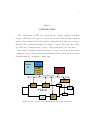
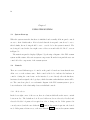
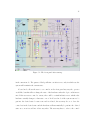
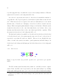
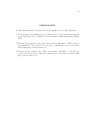
1
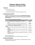
TCS-U Vacuum Control System
Bjørn Hansen
A dissertation submitted in partial fulfillment
of the requirements for the degree of
Master of Science in Aeronautics and Astronautics
University of Washington
2007
Program Authorized to Offer Degree: Aeronautics & Astronautics
University of Washington
Graduate School
This is to certify that I have examined this copy of a master’s thesis by
Bjørn Hansen
and have found that it is complete and satisfactory in all respects,
and that any and all revisions required by the final
examining committee have been made.
Committee Members:
Alan L. Hoffman
Thomas R. Jarboe
Date:
In presenting this thesis in partial fulfillment of the requirements for a master’s degree at
the University of Washington, I agree that the Library shall make its copies freely available
for inspection. I further agree that extensive copying of this thesis is allowable only for
scholarly purposes, consistent with “fair use” as prescribed in the U.S. Copyright Law. Any
other reproduction for any purpose or by any means shall not be allowed without my written
permission.
Signature
Date
University of Washington
Abstract
TCS-U Vacuum Control System
Bjørn Hansen
Chair of the Supervisory Committee:
Professor Alan Hoffman
Aeronautics and Astronautics Engineering
This paper describes the design, implementation, and usage of the Vacuum Control System for the TCS-U plasma experiment. Installation of the required software for system
development is also described, as is configuration of hardware controlled by the system.
TABLE OF CONTENTS
Page
List of Figures . . . . . . . . . . . . . . . . . . . . . . . . . . . . . . . . . . . . . . . . iii
List of Tables . . . . . . . . . . . . . . . . . . . . . . . . . . . . . . . . . . . . . . . . . iv
Glossary . . . . . . . . . . . . . . . . . . . . . . . . . . . . . . . . . . . . . . . . . . . .
v
Chapter 1:
Introduction . . . . . . . . . . . . . . . . . . . . . . . . . . . . . . . . .
1
Chapter 2:
Installation . . . . . . . . . . . . . . . . . . . . . . . . . . . . . . . . .
3
2.1
The Development Environment . . . . . . . . . . . . . . . . . . . . . . . . . .
3
2.2
Building an Executable . . . . . . . . . . . . . . . . . . . . . . . . . . . . . .
4
Chapter 3:
3.1
Program Overview . . . . . . . . . . . . . . . . . . . . . . . . . . . . .
6
Code and Directory Structure . . . . . . . . . . . . . . . . . . . . . . . . . . .
6
Chapter 4:
Program Execution . . . . . . . . . . . . . . . . . . . . . . . . . . . . .
4.1
Initialization
4.2
The Main Loop . . . . . . . . . . . . . . . . . . . . . . . . . . . . . . . . . . . 10
4.3
Clean Up . . . . . . . . . . . . . . . . . . . . . . . . . . . . . . . . . . . . . . 13
Chapter 5:
. . . . . . . . . . . . . . . . . . . . . . . . . . . . . . . . . . . .
9
9
Using the system . . . . . . . . . . . . . . . . . . . . . . . . . . . . . . 14
5.1
System Start-up . . . . . . . . . . . . . . . . . . . . . . . . . . . . . . . . . . 14
5.2
Controls . . . . . . . . . . . . . . . . . . . . . . . . . . . . . . . . . . . . . . . 14
Chapter 6:
DeviceNet . . . . . . . . . . . . . . . . . . . . . . . . . . . . . . . . . . 19
6.1
Hardware Configuration . . . . . . . . . . . . . . . . . . . . . . . . . . . . . . 19
6.2
DeviceNet through LabVIEW . . . . . . . . . . . . . . . . . . . . . . . . . . . 21
6.3
Digital IO with the WRC1-JDA/48-1 . . . . . . . . . . . . . . . . . . . . . . . 23
6.4
RS232 through a 1782-JDC . . . . . . . . . . . . . . . . . . . . . . . . . . . . 24
Chapter 7:
Conclusion . . . . . . . . . . . . . . . . . . . . . . . . . . . . . . . . . . 27
i
Bibliography . . . . . . . . . . . . . . . . . . . . . . . . . . . . . . . . . . . . . . . . . 29
Appendix A: Troubleshooting . . . . . .
A.1 Turbo Pumps . . . . . . . . . . .
A.2 Cryo Pumps . . . . . . . . . . . .
A.3 Thermal Couple Pressure Gauges
A.4 Capacitance Manometer Gauges
A.5 Main Chamber Ion Gauge . . . .
A.6 Valves . . . . . . . . . . . . . . .
.
.
.
.
.
.
.
.
.
.
.
.
.
.
ii
.
.
.
.
.
.
.
.
.
.
.
.
.
.
.
.
.
.
.
.
.
.
.
.
.
.
.
.
.
.
.
.
.
.
.
.
.
.
.
.
.
.
.
.
.
.
.
.
.
.
.
.
.
.
.
.
.
.
.
.
.
.
.
.
.
.
.
.
.
.
.
.
.
.
.
.
.
.
.
.
.
.
.
.
.
.
.
.
.
.
.
.
.
.
.
.
.
.
.
.
.
.
.
.
.
.
.
.
.
.
.
.
.
.
.
.
.
.
.
.
.
.
.
.
.
.
.
.
.
.
.
.
.
.
.
.
.
.
.
.
.
.
.
.
.
.
.
.
.
.
.
.
.
.
.
.
.
.
.
.
.
30
30
31
32
32
32
32
LIST OF FIGURES
Figure Number
Page
1.1
An overview of the vacuum system DeviceNet architecture . . . . . . . . . . .
1
3.1
3.2
The directory structure of the system . . . . . . . . . . . . . . . . . . . . . .
The layer division of the system . . . . . . . . . . . . . . . . . . . . . . . . . .
6
7
4.1
4.2
Program flow . . . . . . . . . . . . . . . . . . . . . . . . . . . . . . . . . . . . 10
Front Panel Block Diagram Organization . . . . . . . . . . . . . . . . . . . . 11
5.1
5.2
5.3
The front panel after start-up . . . . . . . . . . . . . . .
(a) closed valve. (b) open valve. (c) valve set to open,
valve handle. . . . . . . . . . . . . . . . . . . . . . . . .
Turbo Pump and Cryo Pump Controls . . . . . . . . . .
6.1
The DNetAttribute Interface . . . . . . . . . . . . . . . . . . . . . . . . . . . 20
iii
. . . . .
but not
. . . . .
. . . . .
. . . . . . . 15
open. (d)
. . . . . . . 16
. . . . . . . 17
LIST OF TABLES
Table Number
6.1
Page
Important JDC configuration parameters . . . . . . . . . . . . . . . . . . . . 26
iv
GLOSSARY
National Instruments.
NI:
NI-DNET:
TCS-U:
National Instruments Device Net Interface API.
The Translation, Confinement, and Sustainment Upgrade FRC Experiment.
VI:
Virtual Instrument
SCC:
Source Code Control
0.0.1
Conventions
The following conventions have been used throughout the document:
file or directory names
VI names
button text
v
ACKNOWLEDGMENTS
The author wishes to express sincere appreciation to the scientists and technicians at the
Redmond Plasma Physics Laboratory for their help and feedback in designing the Vacuum
Control System.
vi
1
Chapter 1
INTRODUCTION
The vacuum system on TCS-U is controlled from a computer running a LabVIEW
program, which allows the operator to perform various control tasks through a graphical
interface. The Vacuum Control System software ensures that safety rules are not violated,
which prevents conditions which might cause damage to system components. There is also
an override mode, which allows the operator to disregard the safety logic if necessary
The software communicates with the hardware over a DeviceNet network. All network
communication is done through a National Instruments PCI DeviceNet scanner card, which
is installed in the PC on which the software runs.
Control
PC
Labview
Program
NI-DNet
Interface
Card
DeviceNet
Power Supply
DeviceNet Trunk cable
DeviceNet DIO
Multiplexor
DeviceNet
device
DeviceNet
gauge
Valve
Valve
TCS-U
Valve
RS232
gauge
DeviceNet
to RS232
device
Figure 1.1: An overview of the vacuum system DeviceNet architecture
2
Chapter 2 describes the steps involved in setting up a development environment and
how to build the final executable. In chapter 3 an overview of the code structure of the
Vacuum Control System is given. Chapter 4 takes a step by step look at how the code
executes and outlines the program flow. Chapter 5 illustrate how the system is used by
the person operating the vacuum system. Chapter 6 is a description of various DeviceNet
hardware, how it is configured, and how it interfaces with LabVIEW. Chapter 7 contains
some conclusions and recommendations on how a similar system could be developed.
3
Chapter 2
INSTALLATION
2.1
The Development Environment
In order to set up a development environment on a new machine the LabVIEW development
environment must be installed. If the program will also be run on the same machine (e.g.
for testing), an NI DeviceNet Master card must also be installed on the machine. After
installing LabVIEW and the DeviceNet Master card, the NI D-NET drivers must also be
installed: these should be downloaded from the NI website, rather than using the drivers
provided on the CD that came with the card, as the drivers provided on the CD are older
and do not work correctly.
After installing the hardware and software mentioned above the following steps should
be taken1 :
• Map \\terrance\public to drive X:
• Open LabVIEW
• Click Tools→Source Code Control→Configure SCC Options
• Select “built in”
• Set master directory to X:\Bjorn\LabViewSCC
• Click OK
• Set the local work directory to C:\VacuumControl
1
these steps assume the SCC repository is located on the \\terrance\
public share in the \\
Bjorn\LabViewSCC directory
4
• Select windows NT/2000/XP
• Click OK
• Click OK again
• Click Tools→Source Code Control→Launch SCC Provider
• Select Project “Vacuum Control System (FrontPanel.vi)”
• Click Selections→Select Changed files
• Click File→Get Latest Version
• Close the window.
You should now have a newly checked out copy of the latest version of the Vacuum
Control System. In order to edit any of the VIs in the program, you should open the
VI, click Tools→Source Code Control→Check Out. After making changes, check
your changes in by clicking on Tools→Source Code Control→Check In.
2.2
Building an Executable
When improvements have been made to the Vacuum Control program, a new executable
should be built to replace the one that is normally running and controlling the system.
This is very easy to do, once it is set up. Simply open LabVIEW and select Tools→Build
Application or Shared Library (DLL). Load the build script from
C:\VacuumControlExe\VacuumControlSystemBuildScript.bld. If the build script does
not exist, it can be created in the LabVIEW dialog by choosing appropriate parameters
such as the executable name and output directory and then saving the build script.
Once the build script is loaded, click the Build button. LabVIEW may ask to close some
VIs if there are any open, and ask for confirmation on replacing the old VacuumControl.exe
executable. It will then build the new executable. It is recommended that the running
5
VacuumControl.exe program be shut down prior to pressing the build button. After building
the new executable, it can be run to start the newly upgraded system.
Note that the development version of the Vacuum Control System can be run from
within LabVIEW for testing purposes (after shutting down the executable version); the
new executable should only be built when changes are complete and have been tested.
In the next chapter I will discuss the code and directory structure of the Vacuum Control
System software.
6
Chapter 3
PROGRAM OVERVIEW
3.1
Code and Directory Structure
The program is divided into three layers: an interface layer, a logic layer, and a hardware
layer as shown in Figure 3.2. The VIs have been organized into directories according to
this scheme, shown in Figure 3.1. The exception is that the top level VI, FrontPanel.vi,
is in the top level directory. This makes it quick to locate, which is useful since it is the VI
that is actually run. This is further discussed in Chapter 4.
There is also a utility directory which contains utility functions used by the FrontPanel, and also contains Globals.vi, the global variables used by the program. The tools
directory contains VIs which were created to assist in setting up or maintaining the system,
but are not directly part of the control system software. The Test directory contains VIs
used to test individual devices, independent of the main program. The Documentation
directory contains the documentation for the system.
Figure 3.1: The directory structure of the system
7
Figure 3.2: The layer division of the system
3.1.1
The Interface Layer.
The interface layer is the part of the program that the user sees and interacts with. Any
part of the program which is used to display information on the front panel, or gather user
input, is part of the interface layer.
The Interface directory contains code which is part of, or was used to build, the
interface layer. It is divided into groups of VIs: pumps, gauges, and valves. Each of
these subdirectories contains the display logic sub-vi for the item, as well as a VI called
FrontPanel, which is an example of how the interface will look on the top level FrontPanel.
The controls on the example FrontPanel are wired to the display logic so that the whole
8
unit can be copied and pasted from the block diagram of the example to the block diagram
of the main FrontPanel. This approach was used to save time wiring, as there is much
duplication on the main FrontPanel.
3.1.2
The Logic Layer.
The logic layer is the part of the program which contains the operational rules for the
system. Code in this layer takes signals from the interface layer and ensures that no rules
are broken before the signal is passed to the hardware layer.
The Logic directory contains the code which is part of the logic layer. Each piece of
hardware that has logical conditions which determine the hardware’s allowed state has a VI
in the Logic directory which implements the control rules for that hardware component.
There is also a Composite Logic VI, which ties all of the individual pieces together. The
Composite Logic VI ties the logic layer to the interface and hardware layers.
3.1.3
The hardware Layer.
The Hardware directory contains VIs which serve as interfaces for the actual hardware devices attached to the system. There is a separate VI for every DeviceNet device. All of these
hardware VIs send and receive data to and from the hardware through the DNetHardware
VI.
To facilitate development and testing of the system before the actual hardware was in
place, the actual calls to the hardware operations in each subVI were enclosed in a case
statement, which allowed easy switching between simulated hardware and real hardware.
This proved to be an effective way to test some functionality of the program while the real
hardware was not yet in place.
In the next chapter I will step through the execution sequence of the code and identify
the important parts for understanding the program design and flow.
9
Chapter 4
PROGRAM EXECUTION
The program is run by starting the FrontPanel VI. All other VIs are called from within
FrontPanel, or as subVIs of those called from FrontPanel. The FrontPanel VI uses a
Flat Sequence as its outermost structure, which divides the program into three frames:
the initialization, the main loop, and the cleanup phase, as shown in Figure 4.2, and are
executed in that order. Figure 4.1 shows a more detailed illustration of the overall program
flow (including logic and hardware VI functionality).
4.1
Initialization
When the program starts, all of the code in the first frame (labeled “Initialization” in 4.2)
is executed before entering the second frame (the “Main loop”). The initialization code
performs three tasks.
The first task is to call the DNetHardware VI which ensures that the DeviceNet
interface card is ready to use for device communication before starting the main loop.
The second task is a check of the mode ring to determine the operating mode to start
in. If the mode is anything other than override, all controls on the Front Panel are set to
their default states. This ensures that when device communication starts, the system will
be put into a safe default configuration.
The third task is to create a hardware error queue. Any time a hardware error occurs, the
hardware VI involved will obtain a reference to this queue and place a descriptive message
in the queue. The queue is monitored by the FrontPanel VI and will pop up a dialog to
display any messages placed in the queue.
10
Figure 4.1: Program flow
4.2
4.2.1
The Main Loop
FrontPanel code
After initialization is complete, the program enters the second frame (labeled “Main Loop”
in 4.2), which contains four while loops, which run in parallel. The while loops run until
the stop button is pressed. The upper loop has two tasks. First, it checks if the stop
button has been pressed. If it has, appropriate action, depending on the current mode of
the system, is taken to prepare for system shutdown. Second, the loop checks for changes in
the mode ring control. If the user has attempted to change the mode, a password prompt
11
Figure 4.2: Front Panel Block Diagram Organization
is displayed. Only if a correct password is supplied is any mode change actually effected.
The small lower left loop, labeled Display Errors in Figure 4.2, checks the error queue
for errors and displays a dialog should any hardware errors occur.
The other small loop on the left of the frame, labeled Temperature Logging in Figure 4.2, checks to see if temperature logging is enabled, and if so writes the current
temperature of all thermocouples on TCS-U to a spreadsheet file on the desktop called
TCSU TemperatureLog.xls.
The large loop in the lower right, labeled Check Controls, Run Logic, Update Indicators
in Figure 4.2, contains two structures: a Stacked Sequence and a Case Structure.
The Stacked Sequence was employed mainly for block diagram readability, and to keep
the wiring task manageable. The first frame in the sequence reads the values of the thermocouples on TCS-U and updates the indicators on the front panel. It also passes the values
to the heater control logic, instead of passing through CompositeLogic, because the heater
12
control is independent of the vacuum system control.
The remaining frames in the sequence gather values from all of the controls on the
front panel, and update the indicators with values determined during the previous loop
execution. Once all frames have been executed the program passes the control state values
to the CompositeLogic VI.
4.2.2
CompositeLogic
Since there are many control states used in the system logic, individual control outputs are
bundled into clusters before being passed to the CompositeLogic VI. The clusters are
then unbundled inside the CompositeLogic VI before being passed to the individual logic
VIs.
The CompositeLogic VI employs a stacked sequence structure as well, again for readability and wiring management reasons. The outputs of many of the subVIs used in the
CompositeLogic VI are used as inputs to many of the other logic subVIs. These outputs
are often wired to an indicator so that they can be read from a local variable, rather than
through direct wiring, which would result in an unmanageable mess of wires.
The output signal from each logic VI is passed to the hardware VI for the DeviceNet
device that the component is attached to. The outputs from the hardware VIs are often
wired to indicators for use as inputs to the logic VIs, and are also bundled into cluster that
are the outputs of the CompositeLogic VI.
4.2.3
Hardware VIs
The hardware VIs for each device take the input signal and convert it to DeviceNet Data,
which is passed to the correct device through the DNetHardware VI. The DNetHardware
keeps an array of Device Object Handles, so the device index passed to the DnetHardware
VI selects which device the data will be sent to.
13
4.3
Clean Up
When the stop button is pressed on the FrontPanel, the top while loop will display a
confirmation dialog to confirm that the system should be shut down. When the user confirms
(presses “OK”) that the system should be shut down, if the system is in normal mode the
loop will set all controls to default. The loop will then exit. The lower loops will then
stop as well. The program will then move to the third frame of the sequence. The code in
this frame gets references to the DeviceNet Interface and all DeviceNet Objects which were
opened from the DNetHardware VI, and closes them.
The next chapter will describe the various controls that are found on the Front Panel of
the Vacuum Control System. It will outline what each control is for, and how to use it.
14
Chapter 5
USING THE SYSTEM
5.1
System Start-up
When the system starts the hardware is initialized and normally all front panel controls
are set to their default values. If it is desired that the front panel controls not be set to
their defaults, the mode ring should be set to override before the system is started. The
mode ring is located in the lower right corner of the screen and is labeled “Mode”, as seen
in Figure 5.1.
The main front panel is displayed (Figure 5.1), showing a diagram of the TCS vacuum
system and the status of the various system components. From the front panel the user can
control all of the components of the vacuum system.
5.2
Controls
There are several different types of controls on the panel. Controls are items that the user
clicks on to set the software state. Each control is labeled to indicate the hardware it
controls. Setting the control state on the interface does not directly effect the hardware,
but instead sends a signal to the logic layer, which determines what hardware states will be
set. The controls are placed over a schematic diagram of the TCS vacuum system to give a
better indication of the relationship between individual controls.
5.2.1
Mode selector
In the lower right corner of the screen, there is a button which allows the user to switch
between modes. The default mode is Normal. Other modes are Override, Disabled, and
Override Disabled. A password is required in order to change modes. If the password is
correctly entered, and the user clicks the OK button, the system is put into the desired
mode. If the password is incorrect, or the user clicks the Cancel button, the system remains
15
Figure 5.1: The front panel after start-up
in the current mode. The password dialog will time out after ten seconds, in which case the
system will remain in the current state.
Normal mode allows the user to set controls on the front panel any way the operator
would like, but this will not change the state of the hardware unless the logic conditions are
met. If the user sets a control to a state, there will be a visual indication as to whether the
hardware actually changes to that state or not. In Normal mode if the system can not be
put into the desired state because some rule is violated, the user may choose to leave the
control set in the desired state and the hardware will automatically be put into the desired
state as soon as it would not violate any rules. The user may have to refer to the control
16
logic rules (Appendix A) to determine the reason a desired setting is disallowed. When the
system is in Normal mode, the background will be blue.
A second mode option is the Override mode. Override mode is much like normal mode,
except that the control logic is bypassed, so the hardware is put in whatever state the user
sets1 . When Override mode is requested, all controls are immediately set to the current
hardware state, so that the act of changing to Override mode will not, in itself, cause any
changes. This is a safeguard against unintended changes to the hardware. When the system
returns from Override mode, the control rules immediately come back into effect, so any
hardware state that was in violation of the control rules is put back into compliance. When
the system is in Override mode the background will be red.
The third and fourth modes available are Disabled and Disabled Override In Disabled
or Disabled Override mode, the system runs the same as in Normal or Override mode
respectively, except that all controls are disabled. These modes are helpful if the user
desires to monitor the system, but wants to guard against any incidental changes. In
Disabled mode, the background will turn gray. In Disabled Override mode, the background
will be red.
5.2.2
Valve Controls
(a)
(b)
(c)
(d)
Figure 5.2: (a) closed valve. (b) open valve. (c) valve set to open, but not open. (d) valve
handle.
The TCS vacuum system has many valves which are controllable from the computer
system. Each controllable valve is represented by the valve symbol (Figure 5.2). Clicking
on the symbol will toggle the valve open or closed. A closed valve is drawn in blue (Figure
1
Caution, it is possible to cause serious damage to the system when the control rules are
disregarded
17
5.2a ), while an open valve is drawn green(Figure 5.2b ). The desired state of the valve
is indicated by the small rectangular ”handle” on the valve symbol (Figure 5.2d ). If the
valve is set by the operator to be in the closed state, the handle will be to the right, and
drawn in blue. If the valve is set to be in the open state, the handle will be to the left, and
drawn drawn in green. The rest of the valve symbol indicates the actual state of the valve.
If the actual valve state and the desired valve state do not match, the discrepancy will be
highlighted by a red box drawn around the valve symbol (Figure 5.2c ).
5.2.3
Turbo Pump Controls
Each turbo pump control has a button for activating the pump, as well as coolant and speed
indicators (Figure 5.3). If the pump is currently off, the button will be blue, with the word
OFF in white lettering. When the pump is on, the button will be green, with the word
ON in white lettering. The lettering indicates the desired state of the pump, and the color
gives an indication of the status. If the button turns red, it means that the desired state of
the pump does not match the actual pump state. So if the button is says ON , but is red,
then the pump is set to be on, but is not actually running for some reason. The small light
labeled “WC” is the cooling water indicator. It will be green if the cooling water is flowing,
and red otherwise. The last indicator for a turbo pump is the speed box. It displays the
current speed (in RPM) of the pump. This is useful to know because the pump button color
will not indicate that the pump is actually on until it is up to speed.
Figure 5.3: Turbo Pump and Cryo Pump Controls
18
5.2.4
Cryo Pump Controls
The two cryo pumps controls are similar to the turbo pump controls (Figure 5.3). The cryos
are considered to be always on, and will only be actively shut off by the control system if they
lose cooling water flow, thus there is no ON/OFF button on the front panel. Each Pump
control does, however, have two buttons for controlling the standby and boost functions of
the pump. There is also a coolant indicator which shows green when the cooling water is
flowing and red when it is not. Each pump also has a temperature reading, which is shown
in the box below the two button controls.
5.2.5
Gauges
Although there are several types of gauges attached to the TCS vacuum system, all of the
gauges work the same way. There is box which displays the gauge reading. When a gauge
is turned off the box will be filled with black.
5.2.6
Fill Pressure Controls
There are numerical boxes above each of the gauges that measure pressure in the gas puff
plenums, which allow a desired pressure for the plenum to be entered. If the valves behind
the plenum are set to be open the system will attempt to raise the plenum pressure to the
desired value by allowing the valves to open until the desired pressure is reached, at which
point they will close.
5.2.7
The STOP button
In the lower left corner, is a button labeled STOP . Pressing the stop button will cause
the program to exit the main loop. If the system is in Normal mode, all controls will be
set to their default state. If the system is in Override mode, the hardware will be left in its
current state. The hardware interface and all device IO objects will then be closed and the
program will terminate.
The next chapter contains information about DeviceNet, and communication with DeviceNet enabled devices through LabVIEW’s NI-DNet interface.
19
Chapter 6
DEVICENET
The hardware is controlled through a National Instruments PCI-DNET DeviceNet interface card, which acts as the Master for all of the slave hardware devices on the DeviceNet
network. The DeviceNet hardware devices are the physical devices attached to TCS-U and
constitute the physical layer of the vacuum system. Reading and writing through the interface card to the hardware is done via the NI-DNET API, a collection of VIs provided with
the card by National Instruments.
6.1
Hardware Configuration
Once the hardware has been set up and connected with the DeviceNet cable, the devices
must be configured. The MacID and baud rate for each device must be set for every device
on the network; this can usually be done via hardware switches on the device. The baud
rate should be the same for all devices1 , and the MacID should be unique for each device.
Some devices will require further configuration before they are ready for use. For example, a digital IO multiplexer must be configured as to which points are to be inputs, and
which are outputs. Each device has its own parameters that can be set; these parameters
should be described in the documentation for each device. Properties for a device can be
set using the DNetAttribute VI in the tools directory once the MacID and baud rate
have been configured.
To set a property for a specific device, the ClassID, InstanceID, and AttributeID (which
comprise the DeviceNet path) for the property must be entered in the corresponding fields
in the DNetAttribute VI. The value of the property can then be read from, or written
to the device using the GET and SET buttons respectively. The DeviceNet path for the
property may be obtained from the device documentation, or it can be deduced by reading
1
the devices on the TCS-U DeviceNet network are all set to 125 kbps
20
Figure 6.1: The DNetAttribute Interface
the eds file that came with the device.
As an example, consider the WRC1-JDA/48-1 device, which is a multiplexer with up to 48
discreet IO points. Each point can be configured as either an input or an output. There are
six banks of eight points. Each bank can be configured by setting the correct property to a
value represented by single byte (eight bits), one bit for each IO point. The following entry,
taken from the eds file for the WRC1-JDA/48-1, contains the information for the parameter
used to configure the discreet IO points in bank 1 of the device.
Param7 =
0,
6,"20 0F 24 7 30 1",
$class 15, inst. 7, att 1
0x0,
24,1,
"DIO Bank 1",
"",
$1 byte int
21
"Check box to enable as discrete output.",
0,0xff,0,
, , , , ;
The string
"20 0F 24 7 30 1"
gives the path2 to the device: class 0F3 instance 7, attribute 1. By setting the appropriate
value for class 15, instance 7, attribute 1, with the DNetAttribute program, each of the
IO points in bank 1 can be configured as an input or an output.
Once the configuration parameters for a device have been set, the device will maintain
the configuration even if the DeviceNet network is powered off. Provided no changes are
made to the system design, the configuration can be done once, prior to running the vacuum
control system software the first time. Only the control system software needs be run at
any subsequent time that the system is brought on-line.
6.2
DeviceNet through LabVIEW
6.2.1
Initialization
The NI-DNET API provides VIs for use in LabVIEW programs to communicate with the
DeviceNet hardware through the PCI-DNET card. The first call must be to the Open
DeviceNet Interface VI, which configures and opens an NI-DNET Interface Object; it
initializes the card for use in the LabVIEW program.
Once the interface is open, various devices can be opened for communication. The
DNetAttribute VI, used to configure the devices, uses an Explicit Messaging Object;
however, for normal IO operations such as the control system software performs, an NIDNET I/O Object is what is needed.
The final step in initializing the system is a call to the Operate DeviceNet Interface
VI, with the “Start” operation code.
2
3
see [2] for a full description of DeviceNet paths
path values are in hexadecimal, 0F is 15 in decimal
22
The above procedure works well for programs that only use one or two devices on the
network, but the Vacuum Control System controls many more devices. In order to initialize
the card and open many devices for use, the Easy IO Config VI is used. This VI configures
the interface device, opens any number of devices for use, and calls the Operate DeviceNet
Interface VI, with the “Start” operation code.
The Vacuum Control System software uses the DNetHardware VI for all interaction
with DeviceNet hardware. The first time a call is made to DNetHardware VI, it will call
the Easy IO Config VI to initialize the DeviceNet network. To make sure the card is
initialized and ready for use before before the main loop begins and starts trying to control
the hardware, a call is made to the DNetHardware VI during program start up.
6.2.2
Device Communication
Once an IO Object has been opened for a device, the Read DeviceNet IO, and Write DeviceNet IO VIs can be used to receive data from and send data to the device. To facilitate
communication, the Convert From DeviceNet Read and Convert For DeviceNet
Write VIs are used to convert between LabVIEW data types, and the raw DeviceNet data
sent and received over the network.
All of the hardware layer components of the Vacuum Control System software that write
data to devices on the network must first convert it to DeviceNet data before passing it to
the DNetHardware VI, along with the index corresponding to the device to which the
data should be sent.
6.2.3
Shutdown
When a LabVIEW program is finished using DeviceNet, it is necessary to close all IO
Objects as well as the interface card. This can be done by using the Close VI, or the Easy
IO Close VI. After the main loop exits in the Vacuum Control System software, the Easy
IO Close VI is used to close all IO Objects and the DeviceNet interface card.
23
6.3
Digital IO with the WRC1-JDA/48-1
6.3.1
Configuring IOs as inputs or outputs
To configure the digital I/O points for the JDA48, use the DNetAttribute VI located in
the Tools folder. Perform the following steps for the device you wish to configure:
1. Set the DeviceMacID to the address of the desired device.
2. Press the Run button in the LabVIEW toolbar.
3. Select “binary” in the format selector.
4. Set the ClassID to 15 and the AttributeID to 1.
5. Set the InstanceID to a value between 6 and 11, depending which IO points
you wish to configure. An InstanceID of 6 corresponds to digital IO points 0-7, 7
corresponds to points 8-15, etc.
6. Press GET to see the current settings of the selected eight IO points. The right
most digit is the lowest. For example, if the InstanceID is six, the right most digit
corresponds to point 0, and the leftmost to point 7. If the setting was successfully
retrieved from the device, the Device Error box should display “E”.
7. Adjust the value next to SET to the desired IO point settings and press SET to
send the settings to the device. Make sure the “AttrDataLength” field is set to 1. If
the operation was successful, the DeviceError should display “10”.
8. Press GET to verify the new settings have taken effect.
9. Change the InstanceID to the next value if more points need to be configured and
GET/SET those parameters as well.
10. When all configuration for this device is complete, press Stop .
For more details on configurable parameters for the JDA/48 see [3].
24
6.4
RS232 through a 1782-JDC
The 1782-JDC is a family of DeviceNet-to-serial link communication gateways that allow
communication with ASCII devices over a DeviceNet network. The JDC allows communication with either RS232, or RS485 devices [4].
The JDC has a five terminal connector for connecting to the DeviceNet network and a
three terminal connector for interfacing with the ASCII serial device it will be connected
to. The serial terminals are RX (receive), TX (transmit), and GND (ground). There is also
a set of hardware switches that allow the DeviceNet address to be set.
6.4.1
Configuring the JDC
The JDC has several parameters which must be set correctly in order to communicate with
a given ASCII device. These are given in Table 6.1. For a list of other parameters which
can be configured for the JDC see the reference manual for the device [4].
The first parameter in Table 6.1, the serial character format (class 15, instance 1, attribute 1), as well as the baud rate (class 15, instance 1, attribute 1), must match the
format and baud rate of the ASCII device the JDC will connect to. The documentation
for the ASCII device should give the necessary information. The third parameter in Table
6.1, the receive delimiter, is the ASCII character which the ASCII device will send as the
terminating character in each message. The JDC will not transmit any received characters
over the DeviceNet network until either the delimiter character is received, or the receive
buffer overflows. The size of the buffer is controlled by the fourth parameter in the table,
the received buffer size (class 15, instance 5, attribute 1), which is the maximum number
of characters that the JDC expects to receive from the ASCII device. The last parameter,
the transmit buffer size, is similar to the receive buffer size, but applies to transmitted
characters.
6.4.2
Sending and Receiving Data
There are two methods to send ASCII data over DeviceNet to the JDC. In both cases, the
first byte of the data is the record number. The JDC only sends ASCII to the serial device
25
once each time the record number is changed. The second byte of the data sent to the JDC
is the length of the ASCII string to transmit, or zero. The remaining bytes are the ASCII
characters. The difference between the two methods is that if the string length byte is zero,
the JDC will transmit all of the consecutive bytes up to and including the character which
has been set as the transmit delimiter. If the string length is non zero, the JDC will send
exactly that number of bytes, regardless of what the characters are. Since the byte array
produced from the LabVIEW Convert for DeviceNet Write VI for a short string has
the length as the first byte, no transmit delimiter is needed, nor is any extra computation
of string length. To send data, a record number must be appended through the Convert
for DeviceNet Write VI, with no byte offset, and then the string to transmit is added at
a byte offset of one.
The format of the received data is similar to the transmitted data, with the addition
of an error byte, which comes after the record number. The third byte, rather than the
second, is then the string length, and the remaining bytes are the ASCII characters that
were received from the serial device.
26
Table 6.1: Important JDC configuration parameters
Parameter
Instance
choices
Default
Serial
1
0=7N2
7N2
Character
1=7E1
Format
2=7O1
3=8N1
4=8N2
5=8E1
6=8O1
Serial
2
Baud Rate
0=9600
9600
1=1200
2=2400
3=4800
4=19.2k
5=38.4k
Receive
3
Delimiter
Receive
Any valid ASCII character
Carriage return (Dhex )
(0-127, 0-255)
5
0-124
20 chars
6
0-124
20 chars
Buffer
Size
Transmit
Buffer
Size
27
Chapter 7
CONCLUSION
The Vacuum Control System for the TCS-U experiment was developed to allow safe
operation of the vacuum system components, while providing an easy to use interface for
the operator. LabVIEW was used extensively in developing the interface and logic for the
system. The connection and communication between the software portion of the system, and
the hardware on the machine, is accomplished using the DeviceNet protocol, which many
of the hardware devices support directly. In cases where devices do not directly support
DeviceNet communication, a DeviceNet capable device is used to bridge between the vacuum
system components that require digital inputs and outputs, or RS232 communication.
There is no doubt that the Vacuum Control System serves as a vital component to TCSU operation. Having a central control console allows a single operator to easily manipulate
and monitor the machine conditions, while the built in logic greatly reduces the chances
of inadvertently causing damage to the system. The software also protects the machine
from catastrophic failures should a component break and conditions change while no one is
monitoring the system.
The choice of LabVIEW as the programming language to implement the software portion of the vacuum system may not, in hindsight, have been the most ideal. While it allows
quick prototyping of interfaces and device communication, it is not trivial to build arbitrary
custom interfaces and, for large projects, special care is required to maintain code readability. Without manual routing of wires and careful thought about block diagram placement,
the code quickly becomes unreadable. In addition, LabVIEW’s built in source code control
functionality is lacking1 . For instance, it is not uncommon for the SCC to refuse to check in
a change, because it thinks the server has a newer version. While LabVIEW has certainly
been sufficient, and the resulting software quite good, another language such as C++ or
1
even the NI engineers don’t recommend the built in SCC
28
Python might have been better suited for the scale and requirements or the TCS-U Vacuum Control System software because those languages offer greater design flexibility to an
experienced programmer.
It is expected that the Vacuum Control System software will continue to be beneficial
and essential during the operation of TCS-U.
29
BIBLIOGRAPHY
[1] National Instruments Corporation. Ni-dnet programmer reference help, May 2004.
[2] Rockwell Support. Everything you need to know to use devicenet explicit messaging (almost). Knowledgebase record G16551 - DeviceNet Basics of Explicit Messaging, January
2002.
[3] Western Reserve Controls, Inc., Exeter Road Akron, OH 44306. WRC1-JDAxx/xx
SmantMux-PlusTM /DeviceNetTM User’s Manual, document pub 17.0 rev 0.70 edition,
March 2000. http://www.wrcakron.com.
[4] Western Reserve Controls, Inc., Exeter Road Akron, OH 44306. 1782-JDC DeviceNet Serial Gateway User’s Manual, document 25.0 rev 5.05 edition, September 2003.
http://www.wrcakron.com.
30
Appendix A
TROUBLESHOOTING
If a component of the system is not behaving as expected, the first thing to do is to
double check the logic to discover which rule is being broken and is not allowing the desired
state to be set. What follows is an itemized list of things to check for common problems
that may arise.
A.1
A.1.1
Turbo Pumps
TP1
If turbo pump one (TP1) will not turn on, make sure that:
• The cooling water light (WC) is green.
• Scroll Pump 1 is ON and Valve 22 (V22) is open.
OR
Scroll Pump 2 is ON.
• Valve 12 (V12) is open.
• Thermal couple five (TC5) is on (the gauge symbol is green) and has a pressure reading
less than 1000 mTorr.
A.1.2
TP2
If turbo pump two (TP2) will not turn on, make sure that:
• The cooling water light (WC) is green.
• Valve 13 (V13) is open.
31
• Thermal couple five (TC5) is on (the gauge symbol is green) and has a pressure reading
less than 1000 mTorr.
A.1.3
TP5
If turbo pump five (TP5) will not turn on, make sure that:
• The cooling water light (WC) is green.
• Valve 16 (V16) is open
• Thermal couple six (TC6) is on (the gauge symbol is green) and has a pressure reading
less than 1000 mTorr
A.2
A.2.1
Cryo Pumps
CP1
If cryo pump one (CP1) will not turn on, make sure that:
• The cooling water light (WC) is green.
Cryo pump one (CP1) can skip its cooldown cycle if:
• Valve 25 (V25) is closed.
• Cryo pump one (CP1) has a temperature less than 20K
A.2.2
CP2
If cryo pump two (CP2) will not turn on, make sure that:
• The cooling water light (WC) is green.
Cryo pump one (CP1) can skip its cooldown cycle if:
• Valve 26 (V26) is closed.
• Cryo pump two (CP2) has a temperature less than 20K
32
A.3
Thermal Couple Pressure Gauges
Thermocouple gauges have no logic, so if there is a problem it is most likely hardware
related. Check all connections.
A.4
Capacitance Manometer Gauges
Capacitance manometer gauges have no logic; check hardware connections. Note the gauges
labeled CM2, CM3, and CM4 are not actually capacitance manometers, but are pressure
transducers, and have no logic.
A.5
Main Chamber Ion Gauge
If the main chamber ion gauge (IG1) will not turn on, check hardware connections.
A.6
A.6.1
Valves
V1
If valve one (V1) will not open, make sure that:
• The main chamber gauge (IG1) is on and reading less than 100 mTorr
OR
Capacitance Manometer one (CM1) is on and reading less than 100 mTorr.
• Valve sever (V7) is closed.
• Valve twenty four (V24) is open.
• Turbo pump one (TP1) is on and up to speed.
A.6.2
V2
If valve two (V2) will not open, make sure that:
• All other valves connected directly to the main chamber (V1, V3, V4, V5, V6, V7,
and V61) are closed
33
• The main chamber ion gauge (IG1) is on with a reading greater than 100 mTorr.
• Thermal couple five (TC5) is on with a reading less than the IG1 reading.
A.6.3
V3
If valve three (V3) will not open, make sure that:
• The main chamber ion gauge (IG1) is on with a reading less than 100 mTorr
OR
Capacitance Manometer one (CM1) is on and reading less than 100 mTorr.
• Turbo pump two (TP2) is on and up to speed.
• Valve two (V2) is closed.
A.6.4
V4
If valve four (V4) will not open, make sure that:
• The main chamber ion gauge (IG1) is on with a reading less than 5 mTorr
OR
Capacitance Manometer one (CM1) is on and reading less than 5 mTorr.
• Cryo pump one (CP1) is on and has a temperature less than 13K.
• Valve 25 (V25) is closed.
A.6.5
V5
If valve five (V5) will not open, make sure that:
• The main chamber ion gauge (IG1) is on with a reading less than 5 mTorr
OR
Capacitance Manometer one (CM1) is on and reading less than 5 mTorr.
34
• Cryo pump two (CP2) is on and has a temperature less than 13K.
• Valve 26 (V26) is closed.
A.6.6
V6
If valve six (V6) will not open, make sure that:
• The main chamber ion gauge (IG1) is on with a reading less than 100 mTorr
OR
Capacitance Manometer one (CM1) is on and reading less than 100 mTorr.
• Turbo pump five (TP5) is on and up to speed.
A.6.7
V7
If valve seven (V7) will not open, make sure that:
• The main chamber ion gauge (IG1) is on with a reading less than 5 mTorr
OR
Capacitance Manometer one (CM1) is on and reading less than 5 mTorr.
A.6.8
V25
• Valve four (V4) is closed.
A.6.9
V26
• Valve five (V5) is closed.
A.6.10
V52-v56
If any of these valves will not open, check that the pressure reading in the plenum to which
they are connected is less than the desired pressure set in the box just above the reading.
35
A.6.11
V61
If valve 61 (V61) will not open, make sure that:
• The valves V1, V2, V3, V4, V5, V6, V7, and V62 are closed.