1
Coreco Imaging • 7075 Place Robert-Joncas, Suite 142 • St-Laurent, Quebec, Canada • H4M 2Z2
http://www.imaging.com
WiT
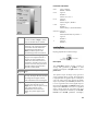
Operator Reference Manual
Edition 8.0
Part number OC-WITM-OPREF
*OC-WITM-OPREF*
NOTICE
© 2003 Coreco Imaging Inc. All rights reserved.
This document may not be reproduced nor transmitted in any form or by any means, either electronic
or mechanical, without the express written permission of Coreco Imaging Inc. Every effort is made to
ensure the information in this manual is accurate and reliable. Use of the products described herein is
understood to be at the user’s risk. Coreco Imaging Inc. assumes no liability whatsoever for the use of
the products detailed in this document and reserves the right to make changes in specifications at any
time and without notice.
Microsoft and MS-DOS are registered trademarks; Windows, Windows 95, Windows NT, and
Windows XP are trademarks of Microsoft Corporation.
All other trademarks or intellectual property mentioned herein belong to their respective owners.
Printed on September 30, 2003
Document Number: OC-WITM-OPREF
Printed in Canada
CONTENTS
CONTENTS ..................................................................i
Standard ....................................................................... 1
Blobs......................................................................... 1
andBlobs .............................................................. 1
getBlobFeatures................................................... 1
getFeatures .......................................................... 4
getPerimeter......................................................... 5
getWarpedFeatures.............................................. 6
getWarpedPerimeter ............................................ 6
labelBlobs ............................................................ 7
mergeFeatures ..................................................... 8
minSizeFeatures................................................... 9
selectBlobs ........................................................... 9
Calculate ................................................................. 10
add ..................................................................... 10
addNoise ............................................................ 10
aluOp ................................................................. 11
applyLut ............................................................. 13
autoEqualize ...................................................... 14
calc1................................................................... 14
calc..................................................................... 15
collectAverage.................................................... 16
compareImages .................................................. 16
complxMult ........................................................ 17
conditional ......................................................... 18
div ...................................................................... 18
equalize .............................................................. 19
false.................................................................... 19
fastAluOp ........................................................... 20
fastUnaryOp....................................................... 21
histEqualize........................................................ 22
invert .................................................................. 22
makeLut.............................................................. 23
makeSeq ............................................................. 24
movingAverage .................................................. 25
mul ..................................................................... 26
not ...................................................................... 26
randSequence..................................................... 27
random............................................................... 28
sub...................................................................... 28
true..................................................................... 29
unaryOp ............................................................. 29
Calibration .............................................................. 30
calibrateCamera.................................................30
calibrateDefault..................................................31
calibrateRatio.....................................................32
calibrateScale.....................................................32
moveOrigin.........................................................32
restoreCoordinates.............................................33
restoreImage.......................................................33
Color .......................................................................34
bayer...................................................................34
convertColor.......................................................35
convertColorFormat...........................................35
getChannel .........................................................36
mergeChannels...................................................37
putChannel .........................................................37
splitChannels......................................................38
Complex ..................................................................38
complexMerge ....................................................38
complexSplit .......................................................39
spectrum .............................................................39
Convert Type...........................................................40
cast .....................................................................40
castImage ...........................................................41
ct.........................................................................42
cvtCase ...............................................................43
formatString .......................................................43
plotEdges............................................................44
plotFeatures .......................................................44
plotGeom ............................................................46
plotLines.............................................................46
scanString...........................................................47
splitString ...........................................................48
sprint ..................................................................49
sscan...................................................................50
strLength ............................................................51
vectorsToImage ..................................................51
Display ....................................................................52
clearDisplay .......................................................52
display ................................................................53
edit......................................................................54
getData...............................................................55
getData2.............................................................57
graph ..................................................................57
iEqualize.............................................................58
iKey ....................................................................59
i
iMeas ................................................................. 60
iThresh ............................................................... 62
overlayData ....................................................... 63
prompt................................................................ 64
runTimeConst..................................................... 65
smallDisplay ...................................................... 66
surface ............................................................... 67
terrain ................................................................ 69
volume................................................................ 70
Edges ...................................................................... 73
getCircularXEdges............................................. 73
getContours........................................................ 74
getXEdges .......................................................... 74
getXEdgesInPoly................................................ 76
getXEdgesOnLine .............................................. 77
traceEdges ......................................................... 78
Filter ....................................................................... 79
compass.............................................................. 79
conv1d................................................................ 80
conv2d................................................................ 80
edgeDetect ......................................................... 81
edgeDirection..................................................... 82
entropy ............................................................... 83
gauss .................................................................. 83
grad.................................................................... 84
hipass1d ............................................................. 85
hipass2d ............................................................. 86
laplace ............................................................... 86
line ..................................................................... 87
lopass1d ............................................................. 88
lopass2d ............................................................. 89
prewitt................................................................ 89
refineEdges ........................................................ 90
sobel................................................................... 91
thinEdges ........................................................... 91
variance ............................................................. 92
Find......................................................................... 92
getMatch ............................................................ 92
getPeaks............................................................. 94
nxcorr................................................................. 95
sod...................................................................... 95
tmatch ................................................................ 96
tmatchSparse...................................................... 98
xCorr.................................................................. 99
Fit.......................................................................... 100
cHough............................................................. 100
convexHull ....................................................... 101
fitCircleToPts................................................... 101
fitLineToPts...................................................... 102
fitTwoLinesToPts ............................................. 103
gCentroid ......................................................... 103
gFitContoursRoi .............................................. 104
ii
gFitLine............................................................104
geom2lines........................................................105
getBoundingBox ...............................................106
getVertexPts .....................................................106
hough................................................................107
houghDir ..........................................................108
houghDirRoi.....................................................108
lineIntersect......................................................109
mergeLines .......................................................109
pix2pt................................................................110
reduceLines ......................................................110
Control ..................................................................112
buf ....................................................................112
cCode ...............................................................112
clearObjs ..........................................................112
collector ...........................................................112
counterInit ........................................................113
counterRecall ...................................................114
counterReset.....................................................114
counterStep.......................................................114
data2sync..........................................................115
delay .................................................................115
for.....................................................................115
for2...................................................................116
for3...................................................................116
gate...................................................................116
goto...................................................................116
if .......................................................................117
if2 .....................................................................117
if3 .....................................................................117
if4 .....................................................................118
ifCond2.............................................................118
ifCond3.............................................................118
ifConditional ....................................................118
in ......................................................................119
label..................................................................119
memConst.........................................................119
memFree...........................................................120
memRecall ........................................................120
memStore..........................................................120
mux5 .................................................................121
mux9 .................................................................121
oneshot .............................................................121
out ....................................................................122
select5...............................................................122
select9...............................................................122
sequencer..........................................................122
start ..................................................................123
stopDisable.......................................................123
stopEnable........................................................123
vgate .................................................................123
Geometry...............................................................123
flip .................................................................... 123
getRigidBodyTransform ................................... 124
getWarpTransform........................................... 125
insertGraphic ................................................... 126
matchSize ......................................................... 126
move................................................................. 127
pan ................................................................... 128
polar................................................................. 128
rotate................................................................ 129
scroll ................................................................ 131
shearX .............................................................. 131
shearY .............................................................. 131
warp ................................................................. 132
zoomScale ........................................................ 132
zoomSize........................................................... 133
Measurement......................................................... 133
caliper .............................................................. 134
distAllPtToPt.................................................... 135
distMap ............................................................ 136
distPtToLine..................................................... 137
getAngle ........................................................... 137
getDist.............................................................. 138
grDistMap........................................................ 138
plotAngle.......................................................... 139
plotDist ............................................................ 140
Morphology .......................................................... 141
bmedian............................................................ 141
dilate ................................................................ 141
erode ................................................................ 143
hitOrMiss ......................................................... 145
ldilate ............................................................... 145
lerode ............................................................... 146
median.............................................................. 146
morphClose...................................................... 147
morphGradient................................................. 148
morphOpen ...................................................... 149
outline .............................................................. 150
rank .................................................................. 151
skeleton ............................................................ 151
thicken.............................................................. 152
thin ................................................................... 153
tophat ............................................................... 153
Objects .................................................................. 154
addElem ........................................................... 154
cat .................................................................... 155
concat............................................................... 155
const................................................................. 156
crGraphic......................................................... 156
crImage ............................................................ 158
crObject ........................................................... 159
crVector ........................................................... 159
createRect ........................................................ 159
filter ..................................................................160
flattenVector .....................................................161
ge......................................................................161
getElem.............................................................162
getField ............................................................162
getRect..............................................................163
getRoi ...............................................................163
getTiles .............................................................164
gf.......................................................................165
partition............................................................165
pf.......................................................................166
putField ............................................................166
renumber ..........................................................168
selectElem.........................................................168
setRoi................................................................169
shuffleVecExpr..................................................169
shuffleVector.....................................................170
sortObj..............................................................171
sortTwoFields...................................................172
swapBytes .........................................................172
tileImages .........................................................173
vecRedim ..........................................................174
Pixel Access ..........................................................174
extract...............................................................174
extractRoi .........................................................175
fill .....................................................................175
getCol ...............................................................176
getPath .............................................................176
getPixel.............................................................177
getRow..............................................................177
getVector ..........................................................178
insert.................................................................178
putCol...............................................................179
putPixel ............................................................179
putRow..............................................................179
putVector ..........................................................180
rasterize............................................................180
sampleLine .......................................................182
zeroImage .........................................................182
Pyramids................................................................183
burt ...................................................................183
burtRecon .........................................................183
burtRecStep ......................................................184
burtStep ............................................................184
decimate ...........................................................185
expand ..............................................................185
fsd .....................................................................186
fsdStep ..............................................................187
gaussPyramid ...................................................187
reduce...............................................................188
showPyramid....................................................188
unDecimate.......................................................189
iii
Segmentation ........................................................ 189
adaptThresh ..................................................... 189
colorThresh...................................................... 190
kMeans............................................................. 191
localAdaptThresh............................................. 192
localPeaks........................................................ 194
localThresh ...................................................... 194
thresh ............................................................... 195
watershed......................................................... 196
zeroX................................................................ 197
Statistics................................................................ 198
backgnd............................................................ 198
bound ............................................................... 198
countPix ........................................................... 199
difference ......................................................... 199
getSlopeMaxima............................................... 200
histCentroid ..................................................... 201
histPeaks .......................................................... 201
histogram ......................................................... 202
projection......................................................... 203
smoothHist ....................................................... 203
stats.................................................................. 204
File IO................................................................... 205
CPUTime ......................................................... 205
chdir................................................................. 205
directory........................................................... 205
exit ................................................................... 206
fileStatus .......................................................... 206
getClipboard .................................................... 207
getTime ............................................................ 207
mkdir................................................................ 207
playSound ........................................................ 208
print ................................................................. 208
putClipboard.................................................... 209
rdText............................................................... 210
readImage ........................................................ 210
readObj............................................................ 212
ringBell ............................................................ 212
splitName ......................................................... 212
stopSound......................................................... 213
stopWatch ........................................................ 213
wrText .............................................................. 213
writeImage ....................................................... 214
writeObj ........................................................... 216
Transforms............................................................ 216
dct .................................................................... 216
fft...................................................................... 217
fht..................................................................... 218
SmartSeries .............................................................. 220
SmartMatrix.......................................................... 220
getBC412 ......................................................... 220
iv
getBarcode .......................................................221
getCCA .............................................................221
getCodabar.......................................................222
getCode128 ......................................................223
getCode39 ........................................................224
getEAN13 .........................................................225
getEAN8 ...........................................................225
getECC200 .......................................................226
getECC200_1 ...................................................227
getECC200_2 ...................................................227
getITF...............................................................228
getPOSTNET ....................................................228
getPharmacode.................................................229
getRSS14 ..........................................................230
getUPCa...........................................................231
getUPCe ...........................................................232
gradeECC200...................................................232
warpMatrix.......................................................233
SmartOCR.............................................................233
ocrBin...............................................................233
ocrEdit..............................................................234
ocrGrayInit.......................................................235
ocrGrayRun......................................................235
ocrLocalBin......................................................238
ocrMakeFont ....................................................239
ocrMakeSemiFont ............................................240
ocrPerimInit .....................................................241
ocrPerimRun ....................................................242
ocrPlotFont ......................................................245
ocrRoiBin .........................................................246
ocrRun..............................................................247
ocrSelectFont ...................................................248
SmartSearch ..........................................................248
patFind1 ...........................................................248
patFind2D1 ......................................................252
patInit1 .............................................................255
patInit2D1 ........................................................257
patInterpolate...................................................259
patLocal1..........................................................259
patRoi1 .............................................................262
patRotate ..........................................................265
patScale............................................................266
patScaleRotate..................................................267
searchEdit ........................................................269
searchRun.........................................................269
SmartWeb .............................................................269
webClusterFeatures..........................................270
webGetBlobFeatsRoi........................................271
webGetBlobFeatures ........................................274
webGetBlobs ....................................................276
webGetBlobsRoi ...............................................278
webGetPerimeter..............................................280
webLabelBlob .................................................. 281
webLineCounter............................................... 282
webPlotFeatures .............................................. 283
webRealign....................................................... 284
webRowExtend................................................. 286
webRowRemove ............................................... 286
webScrollGraphics........................................... 287
webWaterfall.................................................... 287
Frame Grabber and Hardware .............................. 289
SerialIO................................................................. 289
openSerial ........................................................ 289
closeSerial........................................................ 290
readSerial......................................................... 290
writeSerial........................................................ 291
Video Acquisition ................................................. 291
acqColorkey ..................................................... 291
acqCounterRead .............................................. 292
acqCounterReset .............................................. 292
acqDisplay ....................................................... 292
acqExposure..................................................... 293
acqFrameTrigger............................................. 293
acqHue............................................................. 293
acqIoRead ........................................................ 294
acqIoRelease.................................................... 294
acqIoSetup ....................................................... 295
acqIoWrite ....................................................... 295
acqIssueTrigger ............................................... 296
acqLineTrigger ................................................ 297
acqLive............................................................. 297
acqLut .............................................................. 298
acqOverlay....................................................... 298
acqRgbBrightness ............................................ 299
acqSetup........................................................... 299
acqSize ............................................................. 300
acqSnapCount.................................................. 300
acqSource......................................................... 301
acqStart............................................................ 301
acqStop ............................................................ 302
acqSwitchGrab................................................. 302
acqWriteLut ..................................................... 303
acqZoom........................................................... 303
acquire ............................................................. 303
acquireStamped................................................ 304
brightness......................................................... 304
Coreco Imaging Contact Information.................... 307
v
vi
Standard
Demo iGraph
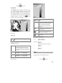
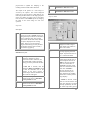
Blobs
The Blobs library provides blob analysis
capabilities. The library includes operators that
extract and process blobs, which are connected
components in binary or labeled images, and a set
of features of the blobs, such as area and centroid.
andBlobs
Operators\Blobs\AndBlobs.igr
Operators\Blobs\Holes.igr
C Prototype
CorOpRtn cor_AndBlobs(
CorBlobVector *A,
CorBlobVector *B,
CorBlobVector *And,
CorBlobVector *NAnd
)
Headers
Feature AND of blobs
#include "$(WITHOME)/h/wBlob.h"
Libraries
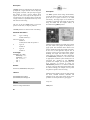
Description
The AndBlobs operator performs an asymmetric
AND of two binary images represented as runlength encoded blobs. The result of the asymmetric
AND of image A with image B is an image
containing those blobs from A which have at least
one pixel in common with one or more blobs from
B. This AND operation is not symmetric, so A
AndBlobs B is not equal to B AndBlobs A.
The AndBlobs operator is applied to vectors of
blobs, run-length encoded regions of contiguous
non-zero pixels, extracted from images using the
getBlobFeatures operator. The output at the And
port is a vector of blobs containing those blobs from
the vector on the A input that have at least one pixel
in common with one or more blobs in the vector on
the B input. The output at the NAnd port is a vector
of those blobs from A that do not have any pixels in
the blobs from B.
The output blob vector can be converted to a feature
vector with the getFeatures operator or into an
image with the labelBlobs operator.
$(WITHOME)/lib/wObj.lib
$(WITHOME)/lib/wBlob.lib
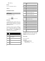
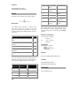
getBlobFeatures
Get Blobs and Blob features from a binary image
Description
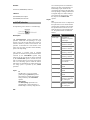
The getBlobFeatures operator computes a number
of features of blobs (connected regions) in a binary
or labeled image. The operator also produces the
blobs in a run length format. The blob perimeters
are optionally calculated.
The input image must be an unsigned 8 or 16-bit
binary or labeled image.
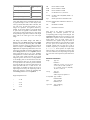
A Blob feature vector describes an object by
measuring centroid location, major and minor axes,
1
bounding boxes, etc.. The Blob feature vector is
sent to the output for use by analysis operators for
object recognition. Blob features may be viewed
using a combination of the plotFeatures and
overlayData operators. The Blob feature vector
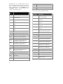
consists of the following fields:
boxarea
xdiff*ydiff
bxaratio
npixels/boxarea
perim
Perimeter data for blob (optional)
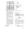
The perimeter fields are defined as follows:
Field
Name
Description
Field Name
Description
id
Unique blob identifier
perimLength
npixels
Number of pixels in the blob (area if
pixels are square)
Total length of perimeter (# of
points) around object
maxDeltaX
xmin
Minimum x-coordinate of blob (left
edge)
Max. distance along x-axis from
x-centroid
minDeltaX
xmax
Maximum x-coordinate of blob (right
edge)
Min. distance along x-axis from xcentroid
maxDeltaY
ymin
Minimum y-coordinate of blob (top
edge)
Max. distance along y-axis from
y-centroid
minDeltaY
ymax
Maximum y-coordinate of blob (bottom
edge)
Min. distance along y-axis from ycentroid
sumRadius
sumx
Sum of all x-coordinates
Sum of radial distances of each
perimeter point from centroid
sumy
Sum of all y-coordinates
sumRadiusSqrd Sum of radial distances squared
sumxsq
Sum of all x-coordinates squared
maxRadiusSqrd Max. radial distance squared
sumysq
Sum of all y-coordinates squared
minRadiusSqrd Min. radial distance squared
sumxy
Sum of all x-coordinates*y-coordinates
maxRadDeltaX Max. distance along x-axis from
x-centroid at max. radial point
perimx
X-coordinate of a pixel on the blob
perimeter (lower right corner)
perimy
Y-coordinate of a pixel on the blob
perimeter (lower right corner)
xc
X-coordinate of blob centroid (sumx/n)
yc
Y-coordinate of blob centroid (sumy/n)
angle
Angle of best fit ellipse major axis
(clockwise from x axis)
major
Length of best fit ellipse major axis
minor
Length of best fit ellipse minor axis
axratio
minor/major
xdiff
xmax-xmin+1
ydiff
ymax-ymin+1
2
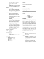
maxRadDeltaY Max. distance along y-axis from
y-centroid at max. radial point
minRadDeltaX
Min. distance along x-axis from xcentroid at max. radial point
minRadDeltaY
Min. distance along y-axis from ycentroid at max. radial point
maxLength
Max. length of perimeter
minLength
Min. length of perimeter
maxWidth
Max. width of perimeter
minWidth
Min. width of perimeter
points
Point vector containing all
perimeter points
The operator also outputs the blobs in the form of a
Blob vector. The Blobs output is a vector that
contains the run lengths that make up the blobs in
the image. Each element of the vector consists of an
id, the row, start and end of the run length, and the
label value of the run length. Run lengths belonging
to the same connected object in the image have the
same id number, which also is the id number of the
corresponding element of the BlobFeatures vector.
The type parameter is used to specify whether the
input image is interpreted as a binary or labeled
image. In a binary image all non-zero valued pixels
are equivalent and blobs are connected regions of
non-zero pixels. Binary images are typically
produced by the thresh operator. In a labeled image
equal valued pixels are equivalent. In this case, the
blobs are connected regions of equal valued pixels.
Labeled images are produced by operators such as
kMeans and watershed.
The connected parameter is used to specify whether
the regions are edge connected (4) or corner
connected (8).
The perimeters of the blobs will be traced and
included in the Blob features if the perimeter
parameter is set to Yes.
The parameters on the Select subpanel allow the
operator to ignore blobs that are smaller or larger
than specified sizes. The minPixels, minWidth and
minHeight parameters specify the minimum
number of pixels, the minimum width (extent in the
x direction) and the minimum height (extent in the y
direction), respectively, of blobs produced. The
maxPixels, maxWidth and maxHeight parameters
specify the maximums for the corresponding
features. If a maximum parameter value is set to
zero, no maximum limit is applied for the
corresponding feature.
If the useMask parameter is set to Yes the blobs use
only pixels in the intersection of the image ROI and
a mask specified by the Mask parameter. The mask
can be specified by a Geometry or Graphic object or
by a binary image. The mask may also be specified
by a vector of Geometry or Graphic objects, binary
images or Blobs. In this case pixels may be used
more than once if the elements overlap in the image.
Parameter Information
type
Type: int
Default: 0
Values: binary: 0, labeled: 1
connected Type: int
Default: 1
Values: 4: 0, 8: 1
perimeters Type: int
Default: 0
Values: No: 0, Yes: 1
useMask
Type: int
Default: 0
Values: No: 0, Yes: 1
mask
Type: CorObj
Default: "OBJ_B T CorGeom 4
CorFpoint 2 0 0 99 99 -"
minPixels Type: int
Default: 0
minWidth Type: int
Default: 0
minHeight Type: int
Default: 0
maxPixels Type: int
Default: 0
maxWidth Type: int
Default: 0
maxHeight Type: int
Default: 0
Demo iGraph
Operators\Blobs\GetBlobFeatures
Operators\Blobs\GetBlobFeaturesMasked
C Prototype
CorOpRtn cor_getBlobFeatures_1(
CorImage *In,
CorFeatureVector *BlobFeatures,
CorBlobVector *Blobs,
int type,
int connected,
int perimeters,
int useMask,
CorObj *mask,
int minPixels,
int minWidth,
int minHeight,
int maxPixels,
3
int maxWidth,
int maxHeight)
ymax
Maximum y-coordinate of blob (bottom
edge)
sumx
Sum of all x-coordinates
sumy
Sum of all y-coordinates
sumxsq
Sum of all x-coordinates squared
sumysq
Sum of all y-coordinates squared
sumxy
Sum of all x-coordinates*y-coordinates
perimx
X-coordinate of a pixel on the blob
perimeter (lower right corner)
perimy
Y-coordinate of a pixel on the blob
perimeter (lower right corner)
xc
X-coordinate of blob centroid (sumx/n)
yc
Y-coordinate of blob centroid (sumy/n)
angle
Angle of best fit ellipse major axis
(clockwise from x axis)
major
Length of best fit ellipse major axis
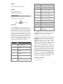
The getFeatures operator computes a feature set for
each blob in the blob vector input. The blob vector
contains run-length encoded blobs, or contiguous
non-zero regions. Blob vectors are produced by the
getBlobFeaures operator.
minor
Length of best fit ellipse minor axis
axratio
minor/major
xdiff
xmax-xmin+1
ydiff
ymax-ymin+1
Each feature set describes a blob by calculating its
centroid location, major and minor axes, bounding
box, etc.. Selected blob features may be viewed
using a combination of the plotFeatures and
overlayData operators. The Blob feature vector
elments consist of the following fields:
boxarea
xdiff*ydiff
bxaratio
npixels/boxarea
perim
Perimeter data for blob (must run the
getPerimeter operator to fill in this
structure)
Field
Name
Description
id
Unique blob identifier
The getField operator may be used to extract any
field given its name for use with operators like
conditional to filter certain object attributes.
npixels
Number of pixels in the blob (area if
pixels are square)
Demo iGraph
xmin
Minimum x-coordinate of blob (left
edge)
Operators\Blobs\Holes
xmax
Maximum x-coordinate of blob (right
edge)
Headers
#include "$(WITHOME)/h/wBlob.h"
Libraries
$(WITHOME)/lib/wObj.lib
$(WITHOME)/lib/wBlob.lib
getFeatures
Generate Blob feature vectors
Description
ymin
4
Minimum y-coordinate of blob (top
edge)
C Prototype
CorOpRtn cor_getFeatures(
CorBlobVector *Blobs,
CorFeatureVector *Features
)
Headers
sumRadiusSqrd Sum of radial distances squared
#include "$(WITHOME)/h/wBlob.h"
maxRadiusSqrd Max. radial distance squared
minRadiusSqrd Min. radial distance squared
Libraries
maxRadDeltaX Max. distance along x-axis from
x-centroid at max. radial point
$(WITHOME)/lib/wObj.lib
$(WITHOME)/lib/wBlob.lib
maxRadDeltaY Max. distance along y-axis from
y-centroid at max. radial point
getPerimeter
minRadDeltaX
Min. distance along x-axis from xcentroid at max. radial point
Find perimeter given a Blob feature
minRadDeltaY
Min. distance along y-axis from ycentroid at max. radial point
maxLength
Max. length of perimeter
minLength
Min. length of perimeter
maxWidth
Max. width of perimeter
minWidth
Min. width of perimeter
points
Point vector containing all
perimeter points
Description
The getPerimeter operator determines the
perimeter related data corresponding to the input
Blob feature vector and its associated input image.
The resulting Blob feature vector is a duplicate of
the input vector with the blob perimeter data set.
Various statistics are generated as part of each
element in the perimeter structure. For example, the
maximum and minimum distance between each
blob centroid and all of its perimeter pixels is
provided. As with the getBlobs operator, any nonzero pixel is considered to be contained in a blob.
The perimeter fields are defined as follows:
Field Name
Description
perimLength
Total length of perimeter (# of
points) around object
maxDeltaX
Max. distance along x-axis from
x-centroid
minDeltaX
Min. distance along x-axis from xcentroid
maxDeltaY
Max. distance along y-axis from
y-centroid
minDeltaY
Min. distance along y-axis from ycentroid
sumRadius
Sum of radial distances of each
perimeter point from centroid
The getField operator may be used to extract any
field given its name for use with operators like
conditional to filter certain object attributes.
Care must be taken to insure that the image used by
getBlobs to generate the blob vector is also used by
getPerimeter to generate the perimeter data. The
connected parameter can be used to specify
whether the perimeter pixels should be eight
connected, where diagonal neighbours are
considered to be touching, or four connected, where
they are not. The type parameter is used to to
specify whether the input image is considered a
binary image, in which case non-zero regions will
be traced, or a labeled image, in which case equal
valued non-zero regions will be traced. In general,
the connected and type parameters should be set to
the same values as the connected and type
parameters on the getBlobs or getBlobFeatures
operator that was used to generate the input Blob
feature vector. If they are not, the operator may
have trouble correctly tracing the perimeter.
Parameter Information
connected Type: int
5
Default: 1
Values: 4: 0, 8: 1
type
Type: int
Default: 0
Values: binary: 0, labeled: 1
Demo iGraph
Operators\Blobs\Holes
C Prototype
CorOpRtn cor_getPerimeter(
CorFeatureVector *In,
CorImage *BinaryImage,
CorFeatureVector *Out,
int connected,
int type
)
Headers
#include "$(WITHOME)/h/wBlob.h"
Libraries
$(WITHOME)/lib/wObj.lib
$(WITHOME)/lib/wBlob.lib
getWarpedFeatures
Generate Blob features of warped objects
The Blob features produced by applying the
getWarpedFeatures operator to the blobs
generated from the unwarped image are
approximately equal to those produced by first
warping the image, then extracting the blobs and
applying the getBlobFeatures operator. The
object's perimeter is not calculated. The
getWarpedPerimeter operator can be applied to
the unwarped Blob feature vector and the unwarped
image to produced the warped perimeter points.
The fields of the Blob feature object are described
in the getBlobFeatures operator documentation.
Demo iGraph
Operators\Blobs\WarpFeatures
C Prototype
CorOpRtn cor_getWarpedFeatures(
CorBlobVector *Blobs,
CorFloatVector *Transform,
CorFeatureVector *Warped
)
Headers
#include "$(WITHOME)/h/wBlob.h"
Libraries
$(WITHOME)/lib/wObj.lib
$(WITHOME)/lib/wBlob.lib
getWarpedPerimeter
Description
The getWarpedFeatures operator computes Blob
feature vectors in a perspective warped image space
for each blob in the blob vector input. The blob
vector
is
produced
by
applying
the
getBlobFeatures operator to the original unwarped
binary image. The feature values are calculated in a
warped image space, which is specified by a
transformation matrix input atthe lower input port
of the operator. The transformation matrix is
typically produced by the getWarpTransform
operator.
6
Find warped perimeter given a Blob feature
Description
The getWarpedPerimeter operator computes
perimeters of binary images and warps them into a
perspective warped image space. The warped space
is specified by a transformation matrix input at the
Transform input port of the operator. The
transformation matrix is typically produced by the
getWarpTransform operator.
The perimeter is determined for each element in the
Blob feature vector input at the Features input port
by tracing the outline of objects in the unwarped
binary image input at the SourceImage port. As
with the getPerimeter operator, the binary image
should be the image from which the blobs used to
produce the Blob feature vector were extracted. The
connected parameter should be set to the same
value as the connected parameter of the
getBlobFeatures operator that produced the blobs.
Notice that in this case the warped perimeter will be
correctly determined, but it will not match the other
features in the Blob feature object.
The perimeters produced by applying the
getWarpedPerimeter operator to a Blob feature
vector generated from the unwarped image are
approximately equal to those produced by first
warping the image, then extracting the Blob feature
vectors and applying the getPerimeter operator.
Parameter Information
connected Type: int
Default: 1
Values: 4: 0, 8: 1
type
Type: int
Default: 0
Values: binary: 0, labeled: 1
Demo iGraph
Operators\Blobs\WarpFeatures
C Prototype
CorOpRtn cor_getWarpedPerimeter(
CorFeatureVector *Features,
CorImage *SourceImage,
CorFloatVector *Transform,
CorFeatureVector *Warped,
int connected,
int type
)
Headers
#include "$(WITHOME)/h/wBlob.h"
Libraries
$(WITHOME)/lib/wObj.lib
$(WITHOME)/lib/wBlob.lib
labelBlobs
Convert blobs to an image
Description
The labelBlobs operator converts the input blob
vector into an image. Blob vectors are produced by
the getBlobFeatures operator.
The mode parameter is used to specify whether the
output image contains the filled blob or just the blob
outline. The blob outline produced by this operator
only includes the end-points of the blob run-lengths
rather than a complete outline of the blob.
The pixel values used for the blobs can be
controlled by the pixelValue parameter. When this
parameter is set to Binary all pixel values in the
blob (or outline) are set to 255; when set to Id the
blob id value is used; and when set to Label the
blob label value is used. For Binary values the
output image is always an 8-bit unsigned image. For
Id or Label the outType parameter can be used to
specify a 16-bit unsigned output image if the id or
label values are expected to exceed 255.
The imageSpec parameter is used to specify the
size and ROI of the output image. This parameter
may be a Point, Real Point, Geometry, Graphic, or
Image object or a vector of Geometry, Graphic,
Image or Blob objects. If the parameter is a Point or
Real Point type value, the x and y values specify the
image width and height and the ROI includes the
entire image. If the parameter is a Geometry or
Graphic object or a vector of Geometry, Graphic or
Blob objects the image and ROI will be the smallest
that can contain the object(s). It the parameter is an
image the output image size and ROI will match the
size and ROI of the parameter image. If the
parameter is a vector of images the output image
7
and ROI will be the smallest size large enough to
contain all of the images in the input image vector.
The imageSpec parameter is often used in the input
mode with the original image from which the blobs
were obtained fed into it to maintain the original
image specifications.
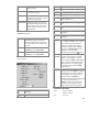
Parameter Information
pixelValue Type: int
Default: 0
Values: Binary: 0, Id: 1, Label: 2
mode
Type: int
Default: 0
Values: Fill: 0, Outline: 1
outType
Type: int
Default: 0
Values: 8-bit: 0, 16-bit: 1
imageSpec Type: CorObj
Default: "OBJ_B T CorPoint 256 256"
Demo iGraph
Operators\Blobs\GetBlobFeatures
Operators\Blobs\GetBlobFeaturesMasked
Description
The mergeFeatures takes a Blob feature vector
produced by the getFeatures operator and
calculates the combined feature values for all the
blobs represented by the input Blob feature vector.
The output is a single Blob feature structure that
contains the size (npixels field), bounding box
(xmin, xmax, ymin, and ymax fields), and so on of
the combined blobs (see the getFeatures operator
for a complete list of fields).
The output Blob feature structure cannot be used as
input to the getPerimeter operator since, in general,
the blobs represented are not connected. The
operator sets the perimx and perimy fields of the
structure to -1 to prevent misuse of the structure.
Parameter Information
id Type: int
Default: 0
Demo iGraph
C Prototype
CorOpRtn cor_labelBlobs(
CorBlobVector *Blobs,
CorImage *Out,
int pixelValue,
int mode,
int outType,
CorObj *imageSpec
)
Headers
Operators\Blobs\MergeFeatures
C Prototype
CorOpRtn cor_mergeFeatures(
CorFeatureVector *In,
CorFeature **Merged,
int id
)
Headers
#include "$(WITHOME)/h/wBlob.h"
#include "$(WITHOME)/h/wBlob.h"
Libraries
Libraries
$(WITHOME)/lib/wObj.lib
$(WITHOME)/lib/wBlob.lib
mergeFeatures
Merge Blob features into a single set of features
8
$(WITHOME)/lib/wObj.lib
$(WITHOME)/lib/wBlob.lib
minSizeFeatures
Libraries
Remove small Blob features from a Blob feature
vector
$(WITHOME)/lib/wObj.lib
$(WITHOME)/lib/wBlob.lib
selectBlobs
Select blobs by blob Id
Description
The minSizeFeatures operator takes an input Blob
feature vector and strips away all blobs that have
fewer pixels than the number specified in the user
parameter minPixels, or are smaller than
minWidth or minHeight. The renumberIds
parameter allows the user to either renumber the
remaining Blob features, starting at a blobs id of 1,
or leave the input Blob feature id's intact.
Parameter Information
minPixels
Type: int
Default: 1
minWidth
Type: int
Default: 1
minHeight
Type: int
Default: 1
renumberIds Type: int
Default: 0
Values: No: 0, Yes: 1
Demo iGraph
Operators\Blobs\MinSizeFeatures
C Prototype
CorOpRtn cor_minSizeFeatures(
CorFeatureVector *In,
CorFeatureVector *Out,
int minPixels,
int minWidth,
int minHeight,
int renumberIds
)
Headers
Description
The selectBlobs operator partitions a blob vector
based on the blob id number. The input is a Blob
vector, a run length encoded representation of a
binary of labeled image produced by the
getBlobFeatures operator. Blobs or contiguous
regions are represented in the Blob vector by run
lengths with the same id number. Run lengths
belonging to the same blob are in scan line order (ie
sorted by increasing row) in the vector. Blobs are
selected by specifying an id number or numbers.
Run lengths with ids matching the specified ids are
output at the as a Blob vector at the Selected output,
all run lengths that do not match one of the
specified ids are output at the NotSelected output.
The ids are specified using the select parameter.
The parameter may be any scalar value or vector of
scalar values, in which case the values are used
directly to specify the ids, or it may be a Feature or
vector of Features, in which case the Feature id
value is used. The Feature vector is also produced
by the getBlobFeatures operator. The Feature id is
the same as blob id from corresponding blobs in the
original image. A typical application selects a
Feature or Features from the Feature vector using
the selectElem or partition operator and applies the
resulting Features to the selectBlobs operator as an
input parameter to obtain the corresponding blobs.
Parameter Information
select Type: CorObj
#include "$(WITHOME)/h/wBlob.h"
9
Demo iGraph
Operators\Blobs\BlobStats
C Prototype
CorOpRtn cor_selectBlobs(
CorBlobVector *Blobs,
CorBlobVector *Selected,
CorBlobVector *NotSelected,
CorObj *select
)
C Prototype
CorOpRtn cor_add(
CorObj *A,
CorObj *B,
CorObj *sum
)
Headers
#include "$(WITHOME)/h/wCalcul.h"
Libraries
Headers
#include "$(WITHOME)/h/wBlob.h"
$(WITHOME)/lib/wObj.lib
$(WITHOME)/lib/wCalcul.lib
Libraries
addNoise
$(WITHOME)/lib/wObj.lib
$(WITHOME)/lib/wBlob.lib
Add noise to an image
Calculate
The Calculate library provides a range of functions
based on arithmetic and logical calculations. The
library includes operators that perform arithmetic
and logical operations on images, vectors and
numeric values; operators that equalize images;
operators that average images; and operators that
produce random or deterministic numbers or
number sequences.
add
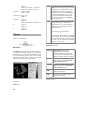
Description
The addNoise operator injects random noise into an
input image thus generating a noisy output image.
The number of pixels to which noise is added is
determined by the affectedArea parameter. This
parameter specifies the probability (as a percentage)
that a pixel will be modified, and corresponds, on
average, to the number pixels changed as a
percentage of the total number of pixels in the
image. The affected pixels are selected randomly.
Add two objects
Description
Add two objects. The objects can be simple scalar
values, such as integers or floating-point numbers,
or vectors or images of such numbers. The type of
the output is promoted to the larger of the two input
types, if they are different. For example, if one of
the inputs is a float and the other one an 8-bit
integer, the result will be a float.
10
The type of noise is selected using the noiseType
parameter and its magnitude is controlled using the
noiseAmount parameter. When the noiseType is
random, a random noise offset is added to the value
of the selected pixel. The amount added varies
uniformly from [0, noiseAmount] for unsigned
images or [-noiseAmount/2, noiseAmount/2] for
signed or float images. If noiseType is spike, then
the value of the selected pixels is set to
noiseAmount. If noiseType is gaussian, the
selected pixel values are offset by gaussian
(normally distributed) noise with a standard
deviation equal to the value of the noiseAmount
parameter. If the noiseAmount parameter is set to
zero, the offset for a selected pixel is drawn from a
gaussian distribution with variance equal to the
pixel value.
reset
Type: int
Default: 0
Values: No: 0, Yes: 1
Demo iGraph
For integer image types, values which fall outside
the image type's range are clipped to the range.
The random number sequence used to generate the
noise can be controlled using the useSeed, seed and
reset parameters. A random number seed is
generated the first time an operator executes or
when the reset parameter is set to Yes, starting a
new random number sequence. When the reset
parameter is set to No, the random number sequence
is a continuation of the sequence used the last time
the operator executed.
When the useSeed parameter is set to No the initial
random number seed is generated from a value
derived from the system clock, so a different
random number sequence is produced each time the
graph is run. When the useSeed parameter is set to
Yes the value specified in the seed parameter is used
to initialize the random number sequence,
producing repeatable noise patterns in the image.
The seed value is a three element vector of short
integers.
Operators\Calculate\AddNoise
Operators\Calculate\CollectAverage
C Prototype
CorOpRtn cor_addNoise(
CorImage *In,
CorImage *Out,
CorUshortVector *NextSeed,
int affectedArea,
int noiseType,
float noiseAmount,
int useSeed,
CorUshortVector *seed,
int reset
)
Headers
#include "$(WITHOME)/h/wCalcul.h"
Libraries
$(WITHOME)/lib/wObj.lib
$(WITHOME)/lib/wCalcul.lib
The operator's NextSeed output value is the seed
value that will continue the random sequence used
by the operator.
aluOp
Parameter Information
Perform arithmetic and logic operations on two
images
affectedArea Type: int
Default: 50
Values: 0 — 100
noiseType
Type: int
Default: 0
Values: random: 0, spike: 1, gaussian:
2
noiseAmount Type: float
Default: 100
useSeed
seed
Type: int
Default: 0
Values: No: 0, Yes: 1
Type: CorVector
Default: [ 1, 0, 0 ]
Description
The aluOp performs binary arithmetic and logical
operations given two input images, A and B. The
input images may be grayscale or color images.
If both input images are grayscale images they may
be any grayscale type and the output image type
may be selected using the outputType parameter.
The default output image type is selected according
to the following criteria.
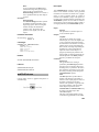
11
Input Image Types
Output Image
Type
OR
bitwise OR of A and B
AND
bitwise AND of A and B
if either input is float
output is float
XOR
bitwise XOR of A and B
otherwise, if either input is 16
bit
output is 16 bit
src
use B where B != 0, else use A
overlay
if either input is signed
output is signed
use B if (A & overlayMask) and B != 0,
else use A
expr
utilize expression to determine result
Color input images may be combined with any type
of grayscale image or with a color image of the
same type (RGB with RGB, HSV with HSV, and
Yuv with Yuv). If both input images are color
images the operations are applied channel by
channel. If one of the images is a grayscale image
its pixel values are applied to each channel of the
color image. If either input image is a color image
the default output type must be selected. The output
image will be the same type as the color input
image.
The aluOp will handle images with ROIs of
different sizes. The sizeOp parameter and the offset
parameter control the processing ROI. The offset
parameter is used to specify an offset for image B
relative to image A. If the sizeOp parameter is set to
clip B then the output image ROI will be set to the
intersection of the ROI of A and the offset ROI of B.
If the sizeOp parameter is set to expand A then the
output image ROI will be set to the bounding
rectangle ROI of A and the offset ROI of B. In this
case, input pixels outside the ROIs of the input
images are given a value of zero, so, using addition
as an example, pixels in the intersection of the two
ROIs will have the value of A + B, pixels in the ROI
of A only will have the value of A, pixels in the ROI
of B only will have the value of B, and pixels not in
either input ROI will have a value of zero. The
output image is normally the same size as the A
input image. If necessary, the output image will be
made large enough to include the bounding ROI
when sizeOp parameter is set to expand A.
Supported operations are:
+
A+B
-
A-B
*
A*B
/
A/B
12
abs(A-B) absolute value of difference between A
and B
min
minimum of A and B
max
maximum of A and B
Each pixel of the output is determined by
performing the indicated operation on the
corresponding pixels in image A and image B. The
expression field allows the user to specify a C style
mathematical equation which will determine the
output image. The top input image can be
referenced in this equation using the variable A
while the bottom image is given using B. The result
for each pixel can be affected by that pixel's
particular column and row using the X and Y
variables respectively. For example, the expression
(Y >= 5) ? A : B will produce an output image
where the first 5 rows are identical to the first five
rows of B. Otherwise, the output image corresponds
to A. For more on the expression syntax and use see
calc.
Parameter Information
aluOp
Type: int
Default: 0
Values: A + B: 0, A - B: 1, A * B: 2,
A / B: 3, OR: 4, AND: 5, XOR: 6,
src: 7, overlay: 8, expr: 9, abs(A-B):
10, min: 11, max: 12
sizeOp
Type: int
Default: 0
Values: clip B: 0, expand A: 1
overlayMask Type: CorHex
Default: 0xffff
offset
Type: CorPoint
Default: (0, 0)
expression
Type: CorString
Default: "A"
outputType
Type: int
Default: 0
Values: default: 0, 8-bit unsigned: 1,
8-bit signed: 2, 16-bit unsigned: 3,
16-bit signed: 4, float: 5
Demo iGraph
Operators\Calculate\AddNoise
Operators\Calculate\CollectAverage
C Prototype
CorOpRtn cor_aluOp(
CorImage *A,
CorImage *B,
CorImage *Out,
int aluOp,
int sizeOp,
CorHex overlayMask,
CorPoint *offset,
CorString expression,
int outputType
)
Headers
#include "$(WITHOME)/h/wCalcul.h"
Libraries
$(WITHOME)/lib/wObj.lib
$(WITHOME)/lib/wCalcul.lib
applyLut
The input image must be one of the integer image
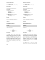
types; unsigned byte, signed byte, unsigned short, or
signed short. The input LUT may be a signed byte,
unsigned byte, signed short, unsigned short, or float
vector. To maintain compatability with earlier
versions of WiT, the input LUT may also be a 32bit signed integer vector. The LUT must include
sufficient elements to cover the range of the input
image; 256 elements for 8-bit images and 65,536
elements for 16-bit images. A LUT in the correct
format can be produced by the makeLut operator.
Except in the case where the input LUT is a signed
int vector, the output image is the same type as the
input LUT. For unsigned input images, the input
image pixel values are used directly as indexes into
the LUT vector. The indexed value from the LUT is
assigned to the corresponding pixel in the output
image. For signed input images, the pixel values are
offset to produce index values that begin at zero.
For example, in a signed byte image a pixel value of
-128 (the minimum pixel value) indexes element 0
of the LUT, a value of -127 indexes element 1, and
so on.
When the LUT is a signed int vector, the output
image is the same type as the input image. The pixel
values are mapped to the LUT elements in the same
way as with other input image types. It is the user's
responsibility to ensure that the LUT element values
are not outside the range of the output image type.
Demo iGraph
Operators\Calculate\Lut
Apply a lookup table on an image
C Prototype
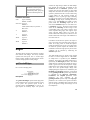
Description
The applyLut operator applies a lookup table
(LUT) received on the bottom input port to an
integer image received at the top input port. The
result is to map each pixel value, z, in the image, I,
to a new pixel value, Z, specified by a precalculated
mapping function, f, to generate a new image, J(Z)
= f(I(z)).
CorOpRtn cor_applyLut(
CorImage *In,
CorVector *Lut,
CorImage *Out
)
Headers
#include "$(WITHOME)/h/wCalcul.h"
13
Libraries
calc1
$(WITHOME)/lib/wObj.lib
$(WITHOME)/lib/wCalcul.lib
Perform arithmetic and logic operations on an
object
autoEqualize
Automatic linear rescaling of image values
Description
Same as calc but with only one input.
Description
The autoEqualize operator performs automatic
image contrast enhancement by computing an
equalization interval based on the input integer
image intensity frequency distribution. The interval
is determined by searching the image histogram
from each end until two values are found for which
a specified percentage of the total image area falls
between each value and the corresponding end of
the histogram. The percentage is controlled through
the fraction parameter. Allowable range is 0-50.
Parameter Information
expression
userConstant Type: double
Default: 0
type
Type: int
Default: 0
Values: default: 0, char: 1, uchar: 2,
short: 3, ushort: 4, int: 5, uint: 6,
float: 7, double: 8
conversion
Type: int
Default: 0
Values: round: 0, floor: 1, ceiling: 2
Parameter Information
fraction Type: float
Default: 5
Demo iGraph
Operators\Calculate\Lut
C Prototype
CorOpRtn cor_autoEqualize(
CorImage *In,
CorImage *Out,
float fraction
)
Type: CorString
Default: "A"
C Prototype
CorOpRtn calc1(
CorObj *In,
CorObj *Out,
CorString expression,
double userConstant,
int type,
int conversion
)
Headers
#include "$(WITHOME)/h/wCalcul.h"
Headers
Libraries
#include "$(WITHOME)/h/wCalcul.h"
$(WITHOME)/lib/wObj.lib
$(WITHOME)/lib/wCalcul.lib
Libraries
$(WITHOME)/lib/wObj.lib
$(WITHOME)/lib/wCalcul.lib
14
calc
< > >= <= ==
!=
boolean comparisons
Perform arithmetic and logic operations on two
input objects
& | ^
bitwise and, or, xor
&& ||
boolean conjunction, boolean
disjunction
Unary operators
Description
The calc operator performs ALU type operations on
two input objects. The input objects may be any
combination of primitive objects or vectors of
primitives. The output is cast to integer or double
following the same casting rules as in the C
programming language. The operation to be
performed is specified by a C style mathematical
expression, entered using the expression parameter.
The userConstant field allows the user to specify a
constant of type double for use in the specified
expression.
There are five case insensitive variables available
for access by the user:
- !
unary negation, boolean not
abs() sqrt()
exp()
absolute value, square root,
e**x
sin() cos()
tan()
trigonometric functions
asin() acos() inverse trigonometric
atan()
functions
log() log10() natural log, log base 10, log
log2()
base 2
floor()
ceil()
round()
General
?
Conditional operator
(comparison) ? (result if true)
: (result if false)
Precedence
parentheses ( ) can be used
to alter precedence
Variable Value
A or a
top input
B or b
bottom input
X or x
current vector column value
Y or y
current vector row value
K or k
the value specified by userConstant
The available operators (ordered by precedence
from highest to lowest) are listed below and may be
used to form the expression:
Note that all calculations are performed using
double precision except for the modulus and bit
operations, which have their operands cast to
integer first. To perform integer division, rather
than floating point division, use floor(A/B) rather
than A/B.
Parameter Information
expression
Binary operators
**
exponentiation
* / %
multiplication, division,
modulus
+ -
addition, subtraction
<< >>
bit shift left, bit shift right
floor, ceiling and rounding
functions. (rint() may be used
in place of round())
Type: CorString
Default: "A"
userConstant Type: double
Default: 0
type
Type: int
Default: 0
Values: default: 0, char: 1, uchar: 2,
short: 3, ushort: 4, int: 5, uint: 6,
float: 7, double: 8
15
conversion
Type: int
Default: 0
Values: round: 0, floor: 1, ceiling: 2
C Prototype
CorOpRtn cor_calc(
CorObj *A,
CorObj *B,
CorObj *Out,
CorString expression,
double userConstant,
int type,
int conversion
)
operator is similar to the collector operator, except
it produces the average or sum of images received
rather than a vector of images.
The operator will accept integer or float gray-scale
images or color images. All images in the sequence
of input images must be the same type and must
have the same ROI. The output image is the same
size as the input image. In the Average mode, the
output image is the same type as the input image. In
the Sum mode, eight bit input images produce 16-bit
output images, while 16-bit integer and float input
images produce float output images.
Headers
Parameter Information
#include "$(WITHOME)/h/wCalcul.h"
number Type: int
Default: 0
Libraries
output Type: int
Default: 0
Values: Average: 0, Sum: 1
$(WITHOME)/lib/wObj.lib
$(WITHOME)/lib/wCalcul.lib
Demo iGraph
collectAverage
Operators\Calculate\CollectAverage
Produce the average or sum of a sequence of images
C Prototype
Description
The collectAverage operator collects a number of
images and forms a single average or sum image
from them. The type parameter value determines
whether an average or sum is formed.
The number of images collected is controlled by the
number parameter. If the number parameter is set
to 0, images are accumulated with no output
produced while integer 0 objects are received at the
Control input. When a non-zero integer object is
received at the Control input the input image is
added to the accumulated image and an output
image is produced. The operator is cleared and a
new sum or average is started when the next image
is received. If number is set to a non-zero value,
the parameter value specifies the number of images
that will be collected to form the output image. The
16
CorOpRtn cor_collectAverage(
CorImage *In,
CorObj *Control,
CorImage *Avg,
int number,
int output
)
Headers
#include "$(WITHOME)/h/wCalcul.h"
Libraries
$(WITHOME)/lib/wObj.lib
$(WITHOME)/lib/wCalcul.lib
compareImages
Compare pixel values in two images.
C Prototype
Description
The compareImages operator performs a pixel by
pixel comparison of the values in two input images
to produce a binary image. The A and B input
images may be any scalar image type (uint8, int8,
uint16, int16, or float32). They do not have to be
the same type. The condition parameter specifies
the test applied to values of corresponding pixels in
images A and B. The tests available are: A < B (A
less than B); A ≤ B (A less than or equal to B); A
== B (A equal to B); A ≥ B (A greater than or equal
to B); A > B (A greater than B); and A != B (A not
equal to B).
The output image is a uint8 binary image. Non-zero
values in the output image indicate pixels in which
the values in the input images meet the specified
condition. The output image is the same size as the
A input image. The output image ROI is set to the
intersection of the ROIs of the two input images.
Pixels values are compared only within the output
image ROI.
An error tolerance can be specified when float
images are compared for equality or inequality
using the floatEqError parameter. Floating point
pixel values will be considered to be equal if the
pixel value from image B is greater than or equal to
the pixel value from image A minus the error
tolerance and less than or equal to the pixel value
from image A plus the error tolerance.
Parameter Information
condition
Type: int
Default: 0
Values: A < B: 0, A <= B: 1, A == B:
2, A >= B: 3, A > B: 4, A != B: 5
floatEqError Type: float
Default: 0
Demo iGraph
Operators\Calculate\CollectAverage
CorOpRtn cor_compareImages(
CorImage *A,
CorImage *B,
CorImage *Out,
int condition,
float floatEqError
)
Headers
#include "$(WITHOME)/h/wCalcul.h"
Libraries
$(WITHOME)/lib/wObj.lib
$(WITHOME)/lib/wCalcul.lib
complxMult
Multiply a complex image by a real or complex
image
Description
The complxMult operator performs pixel by pixel
multiplication of two complex images or of a
complex image and a real image. The A port
accepts a complex image and the B input port
accepts a real (integer or float) image or a second
complex image. The output complex image is the
product of the two input images.
The operator is usually used for processing complex
images produced by a forward fft operation.
Complex images may also be produced from pairs
of float or integer images representing the real and
imaginary components using the complexMerge
operator.
The output image is the same size as the A input
image. The output image ROI is the intersection of
the ROIs of the two input images. Image values
outside the ROI are undefined.
17
Demo iGraph
Operators\Transforms\FourierFilter
C Prototype
Parameter Information
condition Type: int
Default: 0
Values: ==: 0, >: 1, <: 2, !=: 3, >=: 4, <=:
5
CorOpRtn cor_complxMult(
CorImage *A,
CorImage *B,
CorImage *Product
)
Demo iGraph
Headers
C Prototype
#include "$(WITHOME)/h/wCalcul.h"
Libraries
$(WITHOME)/lib/wObj.lib
$(WITHOME)/lib/wCalcul.lib
Operators\Transforms\FourierFilter
CorOpRtn cor_conditional(
CorObj *In0,
CorObj *In1,
int *Out,
int condition
)
Headers
#include "$(WITHOME)/h/wCalcul.h"
conditional
Libraries
Compare numbers or strings and output a boolean
result
$(WITHOME)/lib/wObj.lib
$(WITHOME)/lib/wCalcul.lib
div
Description
Divide one object with another
The conditional operator performs conditional
testing on two inputs. The user selects the condition
operation using the condition parameter. Currently,
the following conditionals are supported:
Description
==
>
<
!=
>=
<=
Divide the first input by the second. See add for
more information about supported types. Dividing a
scalar (first input) by a vector or image is not
allowed.
Demo iGraph
The inputs must be one of the basic WiT types, i.e.,
an integer, float, character, or string. The output
type is an integer and is set to 1 if the conditional is
true and 0 if false.
Operators\Transforms\FourierFilter
C Prototype
CorOpRtn cor_div(
CorObj *A,
CorObj *B,
18
CorImage *Out,
float fromLo,
float fromHi,
float toLo,
float toHi
CorObj *quotient
)
Headers
#include "$(WITHOME)/h/wCalcul.h"
)
Headers
Libraries
#include "$(WITHOME)/h/wCalcul.h"
$(WITHOME)/lib/wObj.lib
$(WITHOME)/lib/wCalcul.lib
equalize
Libraries
$(WITHOME)/lib/wObj.lib
$(WITHOME)/lib/wCalcul.lib
Linear image rescaling
false
Generate a zero-valued integer object
Description
The equalize operator may be used to re-map the
frequency distribution of an image. Pixel values
between the range fromLo to fromHi can be
compressed or expanded to the new range toLo to
toHi. The contrast of an image, for example, may
be increased by choosing a from range which
represents a greyscale area of interest and mapping
these pixels to cover the entire range of the image.
Description
The false operator is used to convert any object
received at its input port into a zero-valued integer
object. This operator is useful for input to a variety
of flow control operators requiring an integer value.
Demo iGraph
Parameter Information
fromLo Type: float
Default: 0
fromHi Type: float
Default: 255
Operators\Calculate\CollectAverage
C Prototype
CorOpRtn cor_false(
int *Out)
toLo
Type: float
Default: 0
Headers
toHi
Type: float
Default: 255
#include "$(WITHOME)/h/wCalcul.h"
Demo iGraph
Libraries
Operators\Transforms\FourierFilter
$(WITHOME)/lib/wObj.lib
$(WITHOME)/lib/wCalcul.lib
C Prototype
CorOpRtn cor_equalize(
CorImage *In,
19
fastAluOp
Faster aluOp, requires same size images
intersection of the ROIs of the A and B images. The
specified operation will only be applied to pixels in
the output image ROI.
Supported operations on input images A and B are:
Description
+
A+B
-
A-B
*
A*B
The fastAluOp performs basic pixel by pixel
arithmetic and logical operations on two input
images. Arbitrary expressions written in the C
language syntax, which may also include the pixel
location, can also be performed.
/
A/B
OR
bitwise OR of A and B
AND
bitwise AND of A and B
XOR
bitwise XOR of A and B
The input images may be grayscale or color images.
If both input images are grayscale images the output
image type is selected according to the following
criteria:
src
use B where B != 0, else use A
overlay
use B if (A & overlayMask) and B !=
0, else use A
Input Image Types
Output Image Type
expr
utilize expression to determine result
abs(A-B)
absolute value of difference between A
and B
if either input is float output is float
min
minimum of A and B
if either input is 16
bit
output is 16 bit
max
maximum of A and B
if either input is
signed
output is signed
Each pixel of the output is determined by
performing the indicated operation on the
corresponding pixels in image A and image B. The
expression field allows the user to specify a C style
mathematical equation which will determine the
output image. The top input image can be
referenced in this equation using the variable A
while the bottom image is given using B. The result
for each pixel can be affected by that pixel's
particular column and row using the X and Y
variables respectively. For example, the expression
(Y >= 5) ? A : B will produce an output image
where the first 5 rows are identical to the first five
rows of B. Otherwise, the output image corresponds
to A. For more on the expression syntax and use see
calc.
Operations may result in values which fall outside
the range of the output type, out of range values are
clipped to the maximum or minimum range value.
To avoid clipping, the input images can be cast a
higher precision type using the castImage or
matchSize operators.
Color input images may be combined with any type
of grayscale image or with a color image of the
same type (RGB with RGB, HSV with HSV, and
Yuv with Yuv). If both input images are color
images the operations are applied channel by
channel. If one of the images is a grayscale image
its pixel values are applied to each channel of the
color image. The output image will be the same
type as the color input image.
The output image will be the same size as the A
input image. The output image ROI will be the
20
This operator is faster than aluOp, but has some
limitations on manipulation of the image ROI and
does not allow the specification of the output image
type. Relative offset can be set and image size
matched using the matchSize operator.
Parameter Information
aluOp
Type: int
Default: 0
Values: +: 0, -: 1, *: 2, /: 3, OR: 4,
AND: 5, XOR: 6, src: 7, overlay: 8,
expr: 9, abs(A-B): 10, min: 11, max:
12
overlayMask Type: CorHex
Default: 0xffff
expression
Type: CorString
Default: "A"
Demo iGraph
Operators\Calculate\CollectAverage
C Prototype
CorOpRtn cor_fastAluOp(
CorImage *A,
CorImage *B,
CorImage *Out,
int aluOp,
CorHex overlayMask,
CorString expression
)
Headers
#include "$(WITHOME)/h/wCalcul.h"
Libraries
written in the C language syntax, which may also
include the pixel location, can also be performed.
The operator supports grayscale and color input
images. If the input image is a grayscale image then
the input constant must be a numeric value. If the
input constant is an integer, the output image type is
the same as the input image type. If the input
constant is a float or double the output image is a
float image, regardless of input image type. Out of
range values for integer images are clipped to the
range of the image type. If the input image is a color
image then the input constant may be a color object
of the same type as the input image or a numeric
value. In this case the output image will be the same
type as the input image.
Supported operations for an image A and a scalar K
are:
+
A+K
-
A-K
*
A*K
/
A/K
|
logical OR
&
logical AND
>>
shift right
<<
shift left
expression utilize expression to determine result
$(WITHOME)/lib/wObj.lib
$(WITHOME)/lib/wCalcul.lib
fastUnaryOp
Faster unaryOp
Description
The fastUnaryOp operator performs basic
arithmetic and logical operations involving an
image and a scale value. Arbitrary expressions
The indicated operation is performed on each pixel
in A. The expression field allows the user to specify
a C style mathematical equation which will
determine the output image. The image can be
specified in this equation using the variable A while
the constant is specified using K. The result for each
pixel can be affected by that pixel's particular
column and row using the X and Y variables
respectively. For example, the expression (X >= 5)
? (A >> K) : A will produce an output image where
every pixel was right shifted by K bits, unless the
pixel fell within the first five columns of the image.
For more on the expression syntax and use see calc.
This operator is faster than unaryOp, but does not
allow the specification of the output image type.
21
Parameter Information
unaryOp
Type: int
Default: 0
Values: +: 0, -: 1, *: 2, /: 3, OR: 4,
AND: 5, >>: 6, <<: 7, expr: 8
expression Type: CorString
Default: "A"
Demo iGraph
Operators\Calculate\CollectAverage
C Prototype
CorOpRtn cor_fastUnaryOp(
CorImage *A,
CorObj *Constant,
CorImage *Out,
int unaryOp,
CorString expression
)
Headers
The output image produced is the same type as the
input image.
A mask can be used to specify which pixels are
used to calculate the equalization mapping. If the
useMask parameter is set to No all pixels in the
image ROI are used. If the useMask parameter is
set to Yes the pixels in the intersection of the image
ROI and a mask specified by the Mask parameter
are used to calculate the mapping. The mask can be
specified by a Geometry or Graphic object or by a
binary image. The mask may also be specified by a
vector of Geometry or Graphic objects, binary
images or Blobs. Once the mapping has been
determined equalization is applied to the entire
image ROI.
Parameter Information
useMask Type: int
Default: 0
Values: No: 0, Yes: 1
mask
#include "$(WITHOME)/h/wCalcul.h"
Type: CorObj
Default: "OBJ_B T CorGeom 4
CorFpoint 2 0 0 99 99 -"
Libraries
Demo iGraph
$(WITHOME)/lib/wObj.lib
$(WITHOME)/lib/wCalcul.lib
Operators\Calculate\HistEqualize
histEqualize
Histogram equalization
C Prototype
CorOpRtn cor_histEqualize_1(
CorImage *In,
CorImage *Out,
int useMask,
CorObj *mask
)
Headers
Description
#include "$(WITHOME)/h/wCalcul.h"
The histEqualize operator may be used to re-map
the frequency distribution of an image so that the
image histogram is approximately flat. This has the
effect of spreading the range around values found in
many pixels and compressing the range around
values found in few pixels. This often has the effect
of improving perceived image contrast around the
dominant values in the image. It should be noted
that precision of the relative image values cannot be
improved by this method.
Libraries
22
$(WITHOME)/lib/wObj.lib
$(WITHOME)/lib/wCalcul.lib
invert
Invert an image
Description
Description
The invert operator inverts the input image. The
input image must be an integer, float or color image
type.
Unsigned integer images and color images are
inverted using the formula: nz = Z - z, where Z is
the maximum pixel value for the input image type, z
is the old pixel value, and nz is the new pixel value.
Signed integer images are inverted using the
formula: nz = -(z + 1). Float images are inverted
using the fomula nz = -z. The output image is the
same type as the input image.
Demo iGraph
Operators\Calculate\HistEqualize
C Prototype
CorOpRtn cor_invert(
CorImage *In,
CorImage *Out
)
CorOpRtn cor_invert_consume(
CorImage *In
)
Headers
#include "$(WITHOME)/h/wCalcul.h"
Libraries
$(WITHOME)/lib/wObj.lib
$(WITHOME)/lib/wCalcul.lib
makeLut
Generate a lookup table
The makeLut operator produces a lookup table
(LUT) by parsing a C expression representing the
desired mapping function. The LUT is used as an
input to the applyLut operator to implement point
operations on images.
The LUT provides a mapping from the integers A
over the range of the pixel values in the expected
input image type (for the applyLut operator) to
pixel values in the output image. The mapping is
specified by a function f(A) as defined by the
parameter
expression.
The
userConstant
parameter allows the user to specify a constant for
use within the expression. For more on the syntax
and usage of expression see calc.
The LUT is output from the operator as a vector of
values in which the size of the vector and type of
the values is determined by the inputType and
outputType parameters. The inputType parameter
must be set to the type of input images expected to
be applied to the applyLut operator. It may be set
to one of the integer image types; ubyte, byte,
ushort, or short. The size of the output vector is
determined by the range of input type; 256 elements
for ubyte and byte, 65,536 elements for ushort or
short. For the unsigned types, ubyte and ushort, the
vector element indexes correspond directly to the
LUT range values, so the first element contains f(0)
and the i-th element contains f(i). For the signed
types, byte and short, the vector element indexes
correspond to the LUT range values offset so that
the minimum pixel value appears in the first vector
element. For example for a byte image, the first
element contains f(-128) and the i-th element
contains f(i-128).
The outputType parameter determines the type of
the elements of the output vector, which in turn
determines the type of the output image of the
applyLut operator. It may be set to one of the
integer or float image types; ubyte, byte, ushort,
short, or float. The output values are calculated
using floating point arithmetic and, if necessary,
converted to integer values as specified by the
conversion parameter. Fractional values of 0.5 are
always rounded up in the round mode. For the
integer types, values greater than the maximum
value in the image type range are set to the
23
maximum value in the range and values less than
the minimum value in the range are set to the
minimum.
Many of the common mapping functions can be
constructed. Refer to the table below for a list of the
most useful.
Function
Equation
digital negative
f(A) = k - A
where k = maximum
pixel value
k-A
thresholding
(A > threshold) ? k : 0
f(A) = k if A > threshold,
otherwise 0
slicing with background
f(A) = k if r1 <= A <=
r2, otherwise A
(A <= r2) ? ((A >= r1) ?
k : A) : A
slicing without
background
f(A) = k if r1 <= A <=
r2, otherwise 0
(A <= r2) ? ((A >= r1) ?
k : 0) : 0
Default: "A"
userConstant Type: int
Default: 0
inputType
Type: int
Default: 0
Values: ubyte: 0, byte: 1, ushort: 2,
short: 3
outputType
Type: int
Default: 0
Values: ubyte: 0, byte: 1, ushort: 2,
short: 3, float: 4
conversion
Type: int
Default: 0
Values: round: 0, floor: 1, ceiling: 2
Demo iGraph
Operators\Calculate\Lut
C Prototype
range compression
(k/log10(1 + k))*log10(1
f(A) = c*log10(1 +
+ abs(A))
abs(A))
where c = k/log10(1 + k)
bit removal, MSB
f(A) = 2*A%(k + 1)
2*A%(k + 1)
bit removal, LSB
f(A) = 2*(A/2)
2*(A/2)
bit extraction
f(A) = k*(i - 2*j)
where
i = A/2(B - n)
k*(((A/2)**(8 - n)) 2*((A/2)**(8 - (n - 1))))
CorOpRtn cor_makeLut(
CorVector *LUT,
CorString expression,
int userConstant,
int inputType,
int outputType,
int conversion
)
Headers
#include "$(WITHOME)/h/wCalcul.h"
Libraries
$(WITHOME)/lib/wObj.lib
$(WITHOME)/lib/wCalcul.lib
j = A/2(B - (n - 1))
makeSeq
B = number of bits
per image
Generate a vector containing a number sequence
n = nth most
significant bit to
extract
Parameter Information
expression
24
Type: CorString
Description
Demo iGraph
The makeSeq operator produces a sequence of
numbers as a WiT vector by parsing a C expression
representing the desired mapping function from the
vector index values to the vector element values.
Operators\Calculate\Lut
The number of elements in the sequence vector is
specified by the size parameter. The element values
are calculated are as a function of the array index
values (from 0 to size - 1) as defined by the
parameter expression. The symbol A is used to
represent the index value in the expression. The
symbol K is optionally used in the expression to
represent a constant value that is specified in the
userConstant parameter. For more on the syntax
and usage of expression see calc.
C Prototype
CorOpRtn cor_makeSeq(
CorIntVector *Sequence,
CorString expression,
int size,
double userConstant,
int type,
int conversion
)
Headers
#include "$(WITHOME)/h/wCalcul.h"
Libraries
The type of the elements in the output vector is
specified by the type parameter. Calculations are
performed at double precision and cast to the
required output type after the calculations are
completed. The conversion parameter can be used
to specify whether the values are rounded to the
nearest (round), nearest lower (floor) or nearest
greater (ceil) integer value when one of the integer
types is specified. The byte, ubyte, short and ushort
output values outside the range of the type are
truncated to the minimum or maximum range
values.
Parameter Information
expression
size
Type: CorString
Default: "A"
Type: int
Default: 255
userConstant Type: double
Default: 0
type
Type: int
Default: 4
Values: byte: 0, ubyte: 1, short: 2,
ushort: 3, int: 4, uint: 5, float: 6,
double: 7
conversion
Type: int
Default: 0
Values: round: 0, floor: 1, ceiling: 2
$(WITHOME)/lib/wObj.lib
$(WITHOME)/lib/wCalcul.lib
movingAverage
Take the running average of a sequence of images
Description
The movingAverage operator produces an output
image that is an average of the current input image
and previous input images. The way in which the
operator calculates the average is controlled by the
type parameter.
When the type parameter is set to Window the
operator produces the mean of the last N images
received by the operator, where N is the smaller of
the number specified using the number parameter
and total number of images received.
When the type parameter is set to Weighted the
output image is the sum of 1/N times the input
image and (N-1)/N times the previous output image.
Again N is the smaller of the number specified
25
using the number parameter and total number of
images received.
Demo iGraph
Operators\Calculate\Lut
All input images to the operator must be the same
image type and size and the ROIs must be the same.
The output image has the same type, size and ROI
as the input images.
Parameter Information
number Type: int
Default: 4
type
Type: int
Default: 0
Values: Window: 0, Weighted: 1
C Prototype
CorOpRtn cor_mul(
CorObj *A,
CorObj *B,
CorObj *product
)
Headers
#include "$(WITHOME)/h/wCalcul.h"
Libraries
Demo iGraph
Operators\Calculate\Lut
$(WITHOME)/lib/wObj.lib
$(WITHOME)/lib/wCalcul.lib
C Prototype
not
CorOpRtn cor_movingAverage(
CorImage *In,
CorImage *Avg,
int number,
int type
)
Headers
#include "$(WITHOME)/h/wCalcul.h"
Logical NOT
Description
The not operator takes the logical NOT of an input
integer object and sends the result to its output.
Libraries
Demo iGraph
$(WITHOME)/lib/wObj.lib
$(WITHOME)/lib/wCalcul.lib
Operators\Calculate\Lut
mul
C Prototype
Multiply two objects
CorOpRtn cor_not(
int In,
int *Out
)
Headers
Description
Multiply two objects. See add for more information
about supported types.
26
#include "$(WITHOME)/h/wCalcul.h"
Libraries
$(WITHOME)/lib/wObj.lib
$(WITHOME)/lib/wCalcul.lib
The operator's NextSeed output value is the seed
value that will continue the random sequence used
by the operator.
Parameter Information
randSequence
Produce a vector of random integer or float numbers
useSeed Type: int
Default: 0
Values: No: 0, Yes: 1
seed
Type: CorVector
Default: [ 1, 0, 0 ]
number Type: int
Default: 10
Description
The randSequence operator produces a vector of
random integer or float numbers from a uniform
distribution over a specified range. The number of
values produced is specified by the number
parameter. The type of the output vector elements is
specified by the type parameter, and the range of
numbers from which they are selected is specified
by the low and high parameters. The range for
integers is [ceil(low), floor(high)], so if the low and
high values are integers they are both included in
the range. The range for floats is [low, high); that is,
the low value is included in the range, the high
value is not.
The random number sequence used to generate the
numbers can be controlled using the useSeed, seed
and reset parameters. A random number seed is
generated the first time an operator executes or
when the reset parameter is set to Yes, starting a
new random number sequence. When the reset
parameter is set to No, the random number sequence
is a continuation of the sequence used the last time
the operator executed.
When the useSeed parameter is set to No the initial
random number seed is generated from a value
derived from the system clock, so a different
random number sequence is produced each time the
graph is run. When the useSeed parameter is set to
Yes the value specified in the seed parameter is used
to initialize the random number sequence,
producing repeatable sequences of random
numbers. The seed value is a three element vector
of short integers.
type
Type: int
Default: 0
Values: int: 0, float: 1
low
Type: float
Default: 0
high
Type: float
Default: 100
reset
Type: int
Default: 0
Values: No: 0, Yes: 1
Demo iGraph
Operators\Calculate\Lut
C Prototype
CorOpRtn cor_randSequence(
CorVector *Out,
CorUshortVector *NextSeed,
int useSeed,
CorUshortVector *seed,
int number,
int type,
float low,
float high,
int reset
)
Headers
#include "$(WITHOME)/h/wCalcul.h"
Libraries
$(WITHOME)/lib/wObj.lib
$(WITHOME)/lib/wCalcul.lib
27
random
Values: No: 0, Yes: 1
seed
Type: CorVector
Default: [ 1, 0, 0 ]
type
Type: int
Default: 0
Values: int: 0, float: 1
Description
low
Type: float
Default: 0
The random operator produces a random integer or
float number from a uniform distribution over a
specified range. The type of the output value is
specified by the type parameter, and the range of
numbers from which it is selected is specified by
the low and high parameters. The range for integers
is [ceil(low), floor(high)], so if the low and high
values are integers they are both included in the
range. The range for floats is [low, high); that is, the
low value is included in the range, the high value is
not.
high
Type: float
Default: 100
reset
Type: int
Default: 0
Values: No: 0, Yes: 1
Produce a random integer or float number
Demo iGraph
Operators\Calculate\Lut
C Prototype
The random number sequence used to generate the
numbers can be controlled using the useSeed, seed
and reset parameters. A random number seed is
generated the first time an operator executes or
when the reset parameter is set to Yes, starting a
new random number sequence. When the reset
parameter is set to No, the random number sequence
is a continuation of the sequence used the last time
the operator executed.
CorOpRtn cor_random(
CorObj *Out,
CorUshortVector *NextSeed,
int useSeed,
CorUshortVector *seed,
int type,
float low,
float high,
int reset
)
Headers
When the useSeed parameter is set to No the initial
random number seed is generated from a value
derived from the system clock, so a different
random number sequence is produced each time the
graph is run. When the useSeed parameter is set to
Yes the value specified in the seed parameter is used
to initialize the random number sequence,
producing repeatable sequences of random
numbers. The seed value is a three element vector
of short integers.
The operator's NextSeed output value is the seed
value that will continue the random sequence used
by the operator.
Parameter Information
useSeed Type: int
Default: 0
28
#include "$(WITHOME)/h/wCalcul.h"
Libraries
$(WITHOME)/lib/wObj.lib
$(WITHOME)/lib/wCalcul.lib
sub
Subtract two objects
Description
Subtract the second input value from the first input
value. See add for more information about
supported types. Subtracting a vector or image
(second input) from a scalar (first value) is not
allowed.
Demo iGraph
Operators\Calculate\Lut
C Prototype
CorOpRtn cor_sub(
CorObj *A,
CorObj *B,
CorObj *diff
)
C Prototype
CorOpRtn cor_true(
int *Out)
Headers
#include "$(WITHOME)/h/wCalcul.h"
Libraries
$(WITHOME)/lib/wObj.lib
$(WITHOME)/lib/wCalcul.lib
unaryOp
Perform a unary operation on an image using a
value
Headers
#include "$(WITHOME)/h/wCalcul.h"
Description
Libraries
$(WITHOME)/lib/wObj.lib
$(WITHOME)/lib/wCalcul.lib
true
Generate a non-zero valued integer object
Description
The true operator is used to convert any object
received at its input port into a non-zero valued
integer object. This operator is useful for input to a
variety of flow control operators requiring an
integer as input.
Demo iGraph
Operators\Calculate\CollectAverage
The unaryOp operator performs unary operations
when both an image A and a constant K are received
at the top and bottom input ports respectively.
The operator supports grayscale and color input
images. If the input image is a grayscale image then
the input constant must be a numeric value. Output
image image type may be specified using the
outputType parameter. If the input image is a color
image then the input constant may be a color object
of the same type as the input image or a numeric
value. In this case the outputType parameter must
be set to default and output image will be the same
type as the input image.
Supported operations are:
+
A+K
-
A-K
*
A*K
/
A/K
|
logical OR
&
logical AND
29
>>
shift right
<<
shift left
expression utilize expression to determine result
The indicated operation is performed on each pixel
in A. The expression field allows the user to specify
a C style mathematical equation which will
determine the output image. The image can be
specified in this equation using the variable A while
the constant is specified using K. The result for each
pixel can be affected by that pixel's particular
column and row using the X and Y variables
respectively. For example, the expression (X >= 5)
? (A >> K) : A will produce an output image where
every pixel was right shifted by K bits, unless the
pixel fell within the first five columns of the image.
For more on the expression syntax and use see calc.
Libraries
$(WITHOME)/lib/wObj.lib
$(WITHOME)/lib/wCalcul.lib
Calibration
The Calibration library supports 2D calibration,
which provides means to compensate perspective
and lens distortions and convert image coordinates
to real world coordinates.
calibrateCamera
Perform calibration of the camera to avoid
distortions
Parameter Information
unaryOp
Type: int
Default: 0
Values: +: 0, -: 1, *: 2, /: 3, OR: 4,
AND: 5, >>: 6, <<: 7, expr: 8
expression Type: CorString
Default: "A"
outputType Type: int
Default: 0
Values: default: 0, 8-bit unsigned: 1, 8bit signed: 2, 16-bit unsigned: 3, 16-bit
signed: 4, float: 5
Description
The calibrateCamera operator computes a
transformation for correcting perspective and nonlinear lens distortions using a checkerboard pattern.
The resultant calibration object can be used by the
restoreImage and restoreCoordinates operators to
restore images or coordinates (graphic objects)
respectively.
Demo iGraph
Operators\Calculate\CollectAverage
C Prototype
CorOpRtn cor_unaryOp(
CorImage *A,
CorObj *constant,
CorImage *Out,
int unaryOp,
CorString expression,
int outputType
)
Headers
#include "$(WITHOME)/h/wCalcul.h"
30
To use this operator, a physical checkerboard
should be prepared and imaged. The checkerboard
must consist of high contrast and uniform black and
white squares. When the image is taken, the
checkboard must fill the entire image area. It is all
right to have squares only partially visible around
the edges of the image. The length of the side of
each square can be set by the cellSize parameter.
The interpolation parameter determines whether
perspective or bilinear interpolation is used within
each square. The origin parameter can be used to
set the origin and direction of the axes of the
coordinate system of the transformation. If set to
none then coordinate system is computed to
maximize the amount of the image visible after
restoration with the Y axis pointing down, X axis
pointing right and origin close to the left top corner
of the image. In all other cases the origin set at the
corner of the square closest to the selected corner
and have both edges forming the corner fully visible
in the image.
C Prototype
CorOpRtn cor_calibrateCamera(
CorImage *chessBoard,
CorCalibrateInfo **calibrateInfo,
float *proportion,
float cellSize,
int interpolation,
int origin
)
Headers
#include "$(WITHOME)/h/wCalibration.h"
Notice that because natural image coordinate
system has the X-axis down and origin at the upper
left corner, the image will appear to be flipped
depending on the origin setting.
The scale factor is kept in such a way that
measurements in the original image and destination
image are as close as possible. This way the
corrected image and data points can be displayed as
an image similar in size to the original one. The
proportion output is the ratio between physical
units (corresponding to the cellSize paramter) and
pixels. If measurements in physical coordinates are
needed, they can be computed by multiplying
positions and lengths in the corrected image by
proportion. The proportion value can also be used
for the calibrateScale operator so that the correct
pixel to physical coordinate scaling can be applied
automatically when restoreCoordinates is used.
Parameter Information
cellSize
Type: float
Default: 1
interpolation Type: int
Default: 0
Values: perspective: 0, bilinear: 1
origin
Type: int
Default: 0
Values: none: 0, bottomLeft: 1,
topLeft: 2, topRight: 3, bottomRight:
4
Libraries
$(WITHOME)/lib/wObj.lib
$(WITHOME)/lib/wCalibration.lib
calibrateDefault
Create default camera calibration transformation
Description
The calibrateDefault operator creates a calibration
object for a trivial one to one transformation. See
calibrateCamera operator for more interesting
non-trivial transformations. calibrateDefault is
useful for creating a transformation object for
operators that require it, but when no transformation
is necessary. width and height parameteres should
be the same as the size of all images that will the
calibration will be applied to.
Parameter Information
width
Type: int
Default: 640
height
Type: int
Default: 480
Demo iGraph
interpolation Type: int
Default: 0
Values: perspective: 0, bilinear: 1
Operators\Calibration\calibrate.igr
origin
Type: int
Default: 0
31
Values: none: 0, bottomLeft: 1,
topLeft: 2, topRight: 3, bottomRight:
4
C Prototype
CorOpRtn cor_calibrateDefault(
CorCalibrateInfo **calibrateInfo,
int width,
int height,
int interpolation,
int origin
)
Libraries
$(WITHOME)/lib/wObj.lib
$(WITHOME)/lib/wCalibration.lib
calibrateScale
Scale calibration transformation
Headers
#include "$(WITHOME)/h/wCalibration.h"
Description
Libraries
The calibrateScale operator changes a calibration
transformation to scale the object multiplying all
coordenates by scale.
$(WITHOME)/lib/wObj.lib
$(WITHOME)/lib/wCalibration.lib
Parameter Information
calibrateRatio
Calculate scale
calibrations
ratio
scale Type: float
between
two
camera
Description
The calibrateRatio operator computes the scale
ratio between two calibration transformations. It is
useful when some graphic or geometric objects
have been created using an old transformation but a
re-calibration is necessary. The proportion output
from calibrateRatio can be used to scale all the old
coordinates to fit in the new transformation.
C Prototype
CorOpRtn cor_calibrateRatio(
CorCalibrateInfo *calibrateInfoOld,
CorCalibrateInfo *calibrateInfoNew,
float *proportion
)
Headers
#include "$(WITHOME)/h/wCalibration.h"
32
C Prototype
CorOpRtn cor_calibrateScale(
CorCalibrateInfo *calibrateInfo,
CorCalibrateInfo
**calibrateInfoScaled,
float scale
)
Headers
#include "$(WITHOME)/h/wCalibration.h"
Libraries
$(WITHOME)/lib/wObj.lib
$(WITHOME)/lib/wCalibration.lib
moveOrigin
Apply shift
transformation
and
rotation
to
calibration
Description
The moveOrigin operator changes a calibration
transformation to translate the origin (dx, dy) to the
specified location, and to rotate (angle) the
coordinate system about the origin.
Parameter Information
dx
Type: float
dy
Type: float
Graphic object, a vector of Geometry or Graphic
objects, or a vector of Point or Fpoint objects.
Parameter Information
mode Type: int
Default: 0
Values: forward: 0, backward: 1
Demo iGraph
Operators\Calibration\calibrate.igr
angle Type: float
C Prototype
CorOpRtn cor_moveOrigin(
CorCalibrateInfo *calibrateInfo,
CorCalibrateInfo
**transformedCalibrateInfo,
float dx,
float dy,
float angle
)
C Prototype
CorOpRtn cor_restoreCoordinates(
CorObj *coordData,
CorCalibrateInfo *calibrateInfo,
CorObj *transformedData,
int mode
)
Headers
Headers
#include "$(WITHOME)/h/wCalibration.h"
#include "$(WITHOME)/h/wCalibration.h"
Libraries
Libraries
$(WITHOME)/lib/wObj.lib
$(WITHOME)/lib/wCalibration.lib
$(WITHOME)/lib/wObj.lib
$(WITHOME)/lib/wCalibration.lib
restoreCoordinates
restoreImage
Apply calibration transformation to an image
Apply calibration transformation to geometry or
graphic objects
Description
Description
The restoreCoordinates operator transforms
coordinates in the input data object using the
calibrateInfo object created by calibrateCamera
operator. If mode is forward then the
transformation is from screen to real coordinates.
Otherwise the transformation is from real to screen
coordinates. The input may be a Geometry or
The restoreImage operator transforms the input
image using calibrateInfo object created by
calibrateCamera operator. If mode is forward
then the transformation is from screen to real
coordinates. Otherwise the transformation is from
real to screen coordinates.
Parameter Information
mode Type: int
33
Default: 0
Values: forward: 0, backward: 1
Demo iGraph
Operators\Calibration\calibrate.igr
C Prototype
CorOpRtn cor_restoreImage(
CorImage *image,
CorCalibrateInfo *calibrateInfo,
CorImage *transformedData,
int mode
)
Headers
#include "$(WITHOME)/h/wCalibration.h"
Libraries
$(WITHOME)/lib/wObj.lib
$(WITHOME)/lib/wCalibration.lib
Color
The Color library provides support for manipulating
color images. The library includes operators that
convert between color formats and operators that
convert between single and multi-channel images.
bayer
Perform conversion between RGB and Bayer
format
Description
The bayer operator converts images between the
Bayer color image format and RGB. The Bayer
format assigns each pixel in an unsigned eight bit
image the value of one color channel. RGB images
are created by interpolating neighbouring pixel
values to get the two missing color channels at each
34
pixel. RGB images are sampled to create Bayer
format images.
Pixels in a row of a Bayer image alternate between
the green channel value and either the red or the
blue channel value as shown below.
G1
R2
G3
R4
B5
G6
B7
G8
G9
R10
G11
R12
B13
G14
B15
G16
RGB images are converted to the Bayer format by
sampling the appropriate color channel value at
each pixel.
When converting from the Bayer format to an RGB
image, the missing color channel values are
determined
by linear interpolation using
neighbouring pixel values for the color channel in
question. If the method parameter is set to Linear
the interpolated values are used directly in the
output image. If method is set to ColorCorrect
color correction using neighbouring pixel values is
applied. The color correction method usually
produces better looking results when the image
contains sharp vertical or horizontal edges.
Bayer encoded images normally start with a green
pixel in the first column of the first row and a red
pixel in the second column of the first row.
However, if subimages are extracted from a Bayer
encoded image the pattern may be offset. The start
parameter allows the operator to process such
subimages. When set to GR, the operator treats the
first and second pixels of the first row of the Bayer
image as green and red, respectively. This setting
works with standard Bayer images and subimages
in which the upper left corner is located at an even
row and even column. When set to RG the two
pixels are treated as red and green. This setting is
used with subimages in which the upper left corner
is located at an even row and odd column. When set
to BG the two pixels are treated as blue and green.
This setting is used with subimages in which the
upper left corner is located at an odd row and even
column. When set to GB the two pixels are treated
as green and blue. This setting is used with
subimages in which the upper left corner is located
at an odd row and odd column. The start setting
may be used for both encoding and decoding
images.
images. The input and output image types must
correspond to the types specified by the conversion
parameter.
Parameter Information
Conversion to and from Gray images require or
produce 8 bit unsigned images. RGB->Gray
conversions produce a gray scale image that
corresponds to the Y (intensity) channel of a Yuv
image. Gray->RGB conversions produce an RGB
image with equal gray values in all channels at each
pixel.
direction Type: int
Default: 1
Values: RGB->Bayer: 0, Bayer->RGB: 1
method
Type: int
Default: 0
Values: Linear: 0, ColorCorrect: 1
start
Type: int
Default: 0
Values: GR: 0, RG: 1, BG: 2, GB: 3
Demo iGraph
Operators\Color\Bayer
Parameter Information
conversion Type: int
Default: 0
Values: RGB->HSV: 0, HSV->RGB: 1,
RGB->Yuv: 2, Yuv->RGB: 3, RGB>Gray: 4, Gray->RGB: 5
Demo iGraph
C Prototype
CorOpRtn cor_bayer(
CorImage *In,
CorImage *Out,
int direction,
int method,
int start
)
Headers
Operators\Color\HSV
Operators\Color\Brighten
C Prototype
CorOpRtn cor_convertColor(
CorImage *In,
CorImage *Out,
int conversion
)
#include "$(WITHOME)/h/wColor.h"
Headers
Libraries
#include "$(WITHOME)/h/wColor.h"
$(WITHOME)/lib/wObj.lib
$(WITHOME)/lib/wColor.lib
Libraries
convertColor
$(WITHOME)/lib/wObj.lib
$(WITHOME)/lib/wColor.lib
Perform color space conversions
convertColorFormat
Convert between banded and packed color formats
Description
The convertColor operator can be used to convert
RGB images to and from HSV, Yuv, and gray scale
35
Description
Headers
The convertColorFormat operator converts
between the obsolete WIT_RGB banded color
image format and WIT_COLOR packed color
image format. This operator is intended primarily to
maintain compatability for user written operators
that use the WIT_RGB format. Existing WiT
operators that accept color images as input will
process WIT_RGB or WIT_COLOR format
images. Operators that produce color images as
output will produce WIT_COLOR format images.
In the future, new operators or modified operators
that can accept color images may not accept the old
format.
#include "$(WITHOME)/h/wColor.h"
The format change will not affect the operation of
graphs that use only existing WiT operators,
however it may be necessary to add a
convertColorFormat operator to existing graphs
convert color images to the banded format if they
are input to user written operators. In addition, it
may be necessary to convert the output from user
written operators or older stored images to the
packed format if they are input to new WiT
operators or operators that previously did not handle
color input.
This operator is intended to facilitate transition to
the new WIT_COLOR format and we recommend
that operators be converted to use the new format.
Parameter Information
direction Type: int
Default: 0
Values: ->packed: 0, ->banded: 1
Demo iGraph
Libraries
$(WITHOME)/lib/wObj.lib
$(WITHOME)/lib/wColor.lib
getChannel
Get a single channel from a multichannel image
Description
The getChannel operator extracts a single channel
from a multichannel input image. The input image
must be a RGB, HSV, or Yuv image. The output is
an 8 bit unsigned image.
The channel parameter specifies which channel is
extracted from the input image. For RGB, HSV and
Yuv images, respectively, channel 0 is the red, hue,
or Y (intensity) channel; channel 1 is the green,
saturation, or u channel; and channel 2 is the blue,
value, or v channel.
Parameter Information
channel Type: int
Default: 0
Values: 0: 0, 1: 1, 2: 2
Demo iGraph
Operators\Color\HSV
Operators\Color\Brighten
Operators\Color\Brighten
C Prototype
C Prototype
CorOpRtn cor_convertColorFormat(
CorImage *In,
CorImage *Out,
int direction
)
CorOpRtn cor_getChannel(
CorImage *In,
CorImage *Out,
int channel
)
36
Headers
)
Headers
#include "$(WITHOME)/h/wColor.h"
#include "$(WITHOME)/h/wColor.h"
Libraries
Libraries
$(WITHOME)/lib/wObj.lib
$(WITHOME)/lib/wColor.lib
$(WITHOME)/lib/wObj.lib
$(WITHOME)/lib/wColor.lib
mergeChannels
putChannel
Merge three images into a multichannel image
Put an image into one channel of a multichannel
image
Description
The mergeChannels operator combines three
grayscale input images into a multichannel output
images. The input images must be 8 bit unsigned
images. For RGB, HSV and Yuv images,
respectively, ch0 is the red, hue, or Y (intensity)
channel; ch1 is the green, saturation, or u channel;
and ch2 is the blue, value, or v channel.
The output image is an RGB, HSV, or Yuv image,
as specified using the outType parameter. The
output image is the same size as the ch0 input image
and the output image ROI is the intersection of the
input image ROIs.
Parameter Information
outType Type: int
Default: 0
Values: RGB: 0, HSV: 1, Yuv: 2
Demo iGraph
Description
The putChannel operator inserts an image into a
single channel of a multichannel image. The
multichannel input image must be a RGB, HSV, or
Yuv image. The inserted input image must be an 8
bit unsigned image. The output image is the same
type and size of as the multichannel input image.
The output image ROI is the intersection of the
ROIs of the two input images.
The channel parameter specifies the channel into
which the gray scale image is inserted. For RGB,
HSV and Yuv images, respectively, channel 0 is the
red, hue, or Y (intensity) channel; channel 1 is the
green, saturation, or u channel; and channel 2 is the
blue, value, or v channel.
Parameter Information
Operators\Color\HSV
channel Type: int
Default: 0
Values: 0: 0, 1: 1, 2: 2
C Prototype
Demo iGraph
CorOpRtn cor_mergeChannels(
CorImage *Ch0,
CorImage *Ch1,
CorImage *Ch2,
CorImage *Out,
int outType
Operators\Color\Brighten
C Prototype
CorOpRtn cor_putChannel(
37
CorImage *In0,
CorImage *In1,
CorImage *Out,
int channel
)
Libraries
$(WITHOME)/lib/wObj.lib
$(WITHOME)/lib/wColor.lib
Headers
#include "$(WITHOME)/h/wColor.h"
Libraries
$(WITHOME)/lib/wObj.lib
$(WITHOME)/lib/wColor.lib
splitChannels
Split multichannel image into its three component
channels
Description
The
splitChannels
operator
separates
a
multichannel input image into three single channel
output images. The input image must be a RGB,
HSV, or Yuv image. The output images are 8 bit
unsigned images. For RGB, HSV and Yuv images,
respectively, ch0 is the red, hue, or Y (intensity)
channel; ch1 is the green, saturation, or u channel;
and ch2 is the blue, value, or v channel.
Demo iGraph
Operators\Color\HSV
Complex
The Complex library provides support for complex
images. The library includes operators that create
complex images from real images and operators that
extract real components or derived images from
complex images.
complexMerge
Merge real/imaginary component images into a
complex image
Description
The complexMerge operator converts two input
images into a complex output image. The input
parameter determines whether the input images are
interpreted as the the real and imaginary
components of the complex image or as the
magnitude and phase. The operator accepts integer
and float input images and does not accept color or
complex images.
The output image is the same size as the Real/Mag
input image. The output image ROI is the
intersection of the ROIs of the two input images.
Image values outside the ROI are undefined.
C Prototype
CorOpRtn cor_splitChannels(
CorImage *In,
CorImage *Ch0,
CorImage *Ch1,
CorImage *Ch2
)
Headers
#include "$(WITHOME)/h/wColor.h"
38
Parameter Information
input Type: int
Default: 0
Values: real/imag: 0, mag/phase: 1
Demo iGraph
Operators\Transforms\CrossCorrelation
C Prototype
CorOpRtn cor_complexMerge(
CorImage *Real_Mag,
CorImage *Imag_Phase,
CorImage *Complex,
int input
)
Headers
#include "$(WITHOME)/h/wComplex.h"
Demo iGraph
Operators\Transforms\CrossCorrelation
C Prototype
CorOpRtn cor_complexSplit(
CorImage *Complex,
CorImage *Real_Mag,
CorImage *Imag_Phase,
int output
)
Libraries
Headers
$(WITHOME)/lib/wObj.lib
$(WITHOME)/lib/wComplex.lib
#include "$(WITHOME)/h/wComplex.h"
Libraries
complexSplit
Split complex image into its real and imaginary
component images
$(WITHOME)/lib/wObj.lib
$(WITHOME)/lib/wComplex.lib
spectrum
Generate power spectrum of an image
Description
The complexSplit operator converts a complex
image into two float images. The output parameter
determines if the output images are the real and
imaginary components of the complex image or the
magnitude and phase.
The complexSplit operator is typically used to split
the complex output of the fft operator into float
images so they can be processed by other WiT
operators. The processed component images can be
merged into a complex image using the
complexMerge operator.
The output images are the same size and have the
same ROI as the input image. Image values outside
the ROI are undefined.
Parameter Information
output Type: int
Default: 0
Values: real/imag: 0, mag/phase: 1
Description
The spectrum operator converts a complex or float
frequency domain image to a power spectrum
representation. The input image is generally
produced by a forward fft operation or, in the case
of a float input image, by applying the
complexSplit operator the output of the fft. The
operator produces an 8-bit unsigned image that
represents a logarithmic scaling of the input image.
The output image is an 8-bit unsigned image formed
by taking the base 10 logarithm of the squared
magnitude of the input image, scaled to the range 0
to 255. Due to this scaling, pixel values in the
output image cannot be directly related to the input
image values. A value of 1 is added to the squared
magnitude of each image pixel before the logarithm
is taken to ensure that the result is non-negative.
This will distort the spectrum near small magnitude
values.
39
The output image is the same size and has the same
ROI as the input image. Image values outside the
ROI are undefined.
Demo iGraph
Operators\Transforms\Transforms
C Prototype
CorOpRtn cor_spectrum(
CorImage *In,
CorImage *Out
)
Headers
#include "$(WITHOME)/h/wComplex.h"
Libraries
$(WITHOME)/lib/wObj.lib
$(WITHOME)/lib/wComplex.lib
Convert Type
The Convert Type library supports changes in
object type and data representation. The library
includes operators that cast between numeric types;
string management operators; and operators that
prepare objects for display.
numbers. It can be used to cast single objects or
vectors of objects.
Conversions between floating point objects (float
and double types), integer objects (byte, ubyte,
short, ushort, int, uint, hex8, hex16, hex and char
types) and between Point and Real Point objects
result in the value of the input object being assigned
to an output object of the selected type. If the value
of the input object falls outside the range of the
output object type, the value is clipped to the range.
If the input is a vector of one of these types, the
output will be a vector of the same size in which the
elements are of the type specified in the type
parameter.
The conversion parameter determines how float or
double types are converted to one of the integer
output types and how the x and y fields in Real
Point objects are converted to the corresponding
fields in the Point object. Selecting round will set
the output value to the nearest integer of the input
value, floor will set it to the nearest integer less than
or equal to the input value, and ceiling will set it to
the nearest integer greater than or equal to the input
value.
Casting to a String or File type from one of the
floating point, integer or point (including Real
Point) types results in a text string representation of
the value. For example, an int object with value 10
will be converted to the string "10" and a Point
object with x=0, y=0 will be converted to the string
"(0, 0)".
cast
Convert basic object to another type (large icon)
Description
The cast operator converts its input object to the
output type specified by the type parameter. The
operator is primarily used to convert between the
various integer and float object types, including
conversions between Point and Real Point objects,
or to convert numbers to strings or strings to
40
Input String or File type objects can be cast to
numeric types. When a string is converted to a
signed or unsigned integer type it is interpreted
using the C programming language convention.
Strings starting with a "0" are interpreted as octal
numbers and strings starting with "0x" or "0X" are
interpreted as hexadecimal numbers. For example,
the strings "12", "014", and "0xC" are all cast to the
integer 12. If the entire string cannot be converted
to the specified numeric type an error occurs,
halting the igraph.
Parameter Information
type
Type: int
Default: 0
Values: byte: 0, ubyte: 1, short: 2,
ushort: 3, int: 4, uint: 5, float: 6, double:
7, String: 8, File: 9, Point: 10, Real
point: 11, char: 12, hex8: 13, hex16: 14,
hex: 15
conversion Type: int
Default: 0
Values: round: 0, floor: 1, ceiling: 2
C Prototype
CorOpRtn cor_cast(
CorObj *In,
CorObj *Out,
int type,
int conversion
)
Headers
the operators in the Filter and Morphology
libraries. Images in these formats can only be cast in
the Clip conversion mode.
The mode parameter allows the selection of Clip,
which preserves image pixel values where possible,
or one of three mapping modes, which scale pixel
values to fit the output image range. In the Clip
mode original image pixel values are retained where
they fall within the range of the output image type.
Input image pixel values that fall outside the output
image range are set to the range minimum or
maximum, depending on whether they are under or
over the range.
The remaining modes provide a linear mapping
from an input pixel value range to an output pixel
value range.
#include "$(WITHOME)/h/wConvert.h"
Libraries
$(WITHOME)/lib/wObj.lib
$(WITHOME)/lib/wConvert.lib
All mapping modes work in the same way for float
type input images. Float type to integer type casts
map from the range of pixel values in the input
image to the full range of the output image type.
Float type to float type casts map from the range of
pixel values in the input image to the range
specified by the min and max parameters.
castImage
Convert image from one type to another
Description
In the MapRange mode the full range of the input
image type is used as the input image range, so
integer type to integer type casts map from the full
range of the input image type to the full range of the
output image type; and integer type to float type
casts map from the full range of the input image
type to the range specified by the min and max
parametes.
The castImage operator converts an integer or
floating point input image to a specified integer or
floating point type. The input image can be any
scalar image type; int8, int16, int32, uint8, uint16,
uint32, float32, or float64. The output image may
be any scalar image type as specified by the
outType parameter.
In the MapValue mode the range of pixel values in
the input image is used as the input image range, so
integer type to integer type casts map from the
range of pixel values in the input image to the full
range of the output image type; and integer type to
float type casts map from the range of pixel values
in the input image to the range specified by the min
and max parametes.
WiT processing and display operators do not
normally handle int32, uint32, or float64 format
images. Images in these formats can be created
using, for example, the crObject operator or
vectorsToImage operator. Images in the int32
format are used for the kernel parameter in many of
The MapMSB mode is similar to the MapValue
mode except for integer output images the values
are mapped to a range that is at least half the full
range of the output image type. This mode may
41
have a speed advantage over the MapValue mode,
depending on available hardware.
Parameter Information
outType Type: int
Default: 3
Values: int8: 0, int16: 1, int32: 2, uint8: 3,
uint16: 4, uint32: 5, float32: 6, float64: 7
mode
Type: int
Default: 0
Values: Clip: 0, MapRange: 1, MapValue:
2, MapMSB: 3
min
Type: float
Default: 0
max
Type: float
Default: 1
C Prototype
CorOpRtn cor_castImage_1(
CorImage *In,
CorImage *Out,
int outType,
int mode,
float min,
float max
)
CorOpRtn cor_castImage_1_consume(
CorImage *In,
int outType,
int mode,
float min,
float max
)
Headers
#include "$(WITHOME)/h/wConvert.h"
Libraries
$(WITHOME)/lib/wObj.lib
$(WITHOME)/lib/wConvert.lib
ct
Convert basic object to another type
42
Description
The ct (cast) operator converts its input object to the
output type specified by the type parameter. The
operator is primarily used to convert between the
various integer and float object types, including
conversions between Point and Real Point objects,
or to convert numbers to strings or strings to
numbers. It can be used to cast single objects or
vectors of objects.
Conversions between floating point objects (float
and double types), integer objects (byte, ubyte,
short, ushort, int, uint, hex8, hex16, hex and char
types) and between Point and Real Point objects
result in the value of the input object being assigned
to an output object of the selected type. If the value
of the input object falls outside the range of the
output object type, the value is clipped to the range.
If the input is a vector of one of these types, the
output will be a vector of the same size in which the
elements are of the type specified in the type
parameter.
The conversion parameter determines how float or
double types are converted to one of the integer
output types and how the x and y fields in Real
Point objects are converted to the corresponding
fields in the Point object. Selecting round will set
the output value to the nearest integer of the input
value, floor will set it to the nearest integer less than
or equal to the input value, and ceiling will set it to
the nearest integer greater than or equal to the input
value.
Casting to a String or File type from one of the
floating point, integer or point (including Real
Point) types results in a text string representation of
the value. For example, an int object with value 10
will be converted to the string "10" and a Point
object with x=0, y=0 will be converted to the string
"(0, 0)".
Input String or File type objects can be cast to
numeric types. When a string is converted to a
signed or unsigned integer type it is interpreted
using the C programming language convention.
Strings starting with a "0" are interpreted as octal
numbers and strings starting with "0x" or "0X" are
interpreted as hexadecimal numbers. For example,
the strings "12", "014", and "0xC" are all cast to the
integer 12. If the entire string cannot be converted
to the specified numeric type an error occurs,
halting the igraph.
Default: 0
Values: Upper: 0, Lower: 1
C Prototype
Parameter Information
type
Type: int
Default: 0
Values: byte: 0, ubyte: 1, short: 2,
ushort: 3, int: 4, uint: 5, float: 6, double:
7, String: 8, File: 9, Point: 10, Real
point: 11, char: 12, hex8: 13, hex16: 14,
hex: 15
conversion Type: int
Default: 0
Values: round: 0, floor: 1, ceiling: 2
C Prototype
CorOpRtn cor_cast(
CorObj *In,
CorObj *Out,
int type,
int conversion
)
CorOpRtn cor_cvtCase(
CorString Src,
CorString *Dst,
int to
)
Headers
#include "$(WITHOME)/h/wConvert.h"
Libraries
$(WITHOME)/lib/wObj.lib
$(WITHOME)/lib/wConvert.lib
formatString
Concatenate a vector of strings into a string
Headers
#include "$(WITHOME)/h/wConvert.h"
Libraries
$(WITHOME)/lib/wObj.lib
$(WITHOME)/lib/wConvert.lib
cvtCase
Convert a string to all upper or all lower case
Description
The formatString operator concatenates strings
from the input vector and delimiter strings into a
single string. The delimiter strings are specified in
the operator's parameters. The colDelimit string is
inserted after each element except the last. The
prepend string is inserted at the beginning of the
output string and the append string is inserted at the
end.
Multi-column vectors of strings are no longer
supported, so the rowDelimit parameter now has no
effect.
Description
Parameter Information
The cvtCase operator converts the input character
string, src, to either all upper case or all lower case,
depending on the to parameter.
Parameter Information
to Type: int
colDelimit Type: CorString
Default: ""
rowDelimit Type: CorString
Default: ""
prepend
Type: CorString
43
Default: ""
append
Type: CorString
Default: ""
g
Type: int
Default: 0
Values: 0 — 255
b
Type: int
Default: 0
Values: 0 — 255
C Prototype
CorOpRtn cor_formatString(
CorStringVector *In,
CorString *Out,
CorString colDelimit,
CorString rowDelimit,
CorString prepend,
CorString append
)
showArrow Type: int
Default: 0
Values: no: 0, yes: 1
Headers
arrowSize
Type: int
Default: 12
#include "$(WITHOME)/h/wConvert.h"
arrowR
Type: int
Default: 255
Values: 0 — 255
arrowG
Type: int
Default: 255
Values: 0 — 255
arrowB
Type: int
Default: 0
Values: 0 — 255
Libraries
$(WITHOME)/lib/wObj.lib
$(WITHOME)/lib/wConvert.lib
plotEdges
Convert edge vectors to graphic descriptions
Description
The plotEdges operator converts an edge or vector
of edges into a vector of graphic objects that can be
displayed on an image using the overlayData
operator. The graphic objects include a geometric
object for each edge, for example a point for
crossing edges found using getXEdges and may
also include an arrow indicating the edge direction
and a label. Since multiple graphic objects are used
to represent each edge, a single edge input results in
a vector of graphic objects output.
The color of the graphical objects can be selected
using the parameters in the Color subpanel.
C Prototype
CorOpRtn cor_plotEdges(
CorObj *Edges,
CorGraphicVector *PlottedEdges,
int r,
int g,
int b,
int showArrow,
int arrowSize,
int arrowR,
int arrowG,
int arrowB)
Headers
#include "$(WITHOME)/h/wConvert.h"
Libraries
$(WITHOME)/lib/wObj.lib
$(WITHOME)/lib/wConvert.lib
plotFeatures
Parameter Information
r
44
Type: int
Convert Blob feature vectors to graphic descriptions
Values: 0 — 255
penG
Type: int
Default: 0
Values: 0 — 255
penB
Type: int
Default: 0
Values: 0 — 255
fill
Type: int
Default: 0
Values: off: 0, on: 1
fillR
Type: int
Default: 0
Values: 0 — 255
fillG
Type: int
Default: 0
Values: 0 — 255
fillB
Type: int
Default: 0
Values: 0 — 255
Description
The plotFeatures operator converts the input Blob
feature object or vector of Blob features into a
graphic object or vector of graphic objects for
viewing with the overlayData operator. The type of
feature for viewing is specified by the featureType
parameter and can be one of: centroids, ellipse axes,
bounding boxes, perimeters, or centers of bounding
boxes.
In order to plot perimeters, input Blob features must
include the optional perimeter data. Blob feature
vectors produced by the getBlobFeatures operator
with its perimeter parameter set to Yes include
perimeter data. Blob feature vectors produced by
the getBlobFeatures operator with this parameter
set to No or by the getBlobs, getFeatures
combination do not contain perimeter data. The
perimeter data can be added to these blob features
by passing them through the getPerimeter operator.
The color of the output graphics can be controlled
using parameters on the Color subpanel. If the
colors parameter is set to custom the remaining
parameters can be used to specify whether the
output graphics are outlines or filled graphic objects
and to specify the color of the objects. The default
graphics are yellow outlines. The label field of each
graphic object is set to the id number of the
associated element of the Blob feature vector.
Parameter Information
featureType Type: int
Default: 0
Values: centroids: 0, major axis: 1,
bbox: 2, perimeter: 3, bbox center: 4
colors
outline
penR
Type: int
Default: 0
Values: default: 0, custom: 1
Demo iGraph
Operators\Blobs\GetBlobFeatures.igr
Operators\Blobs\GetBlobFeaturesMasked.igr
Operators\Blobs\SelectFeatures.igr
C Prototype
CorOpRtn cor_plotFeatures(
CorObj *Features,
CorObj *PlottedFeatures,
int featureType,
int colors,
int outline,
int penR,
int penG,
int penB,
int fill,
int fillR,
int fillG,
int fillB)
Headers
#include "$(WITHOME)/h/wConvert.h"
Type: int
Default: 0
Values: off: 0, on: 1
Libraries
Type: int
Default: 0
$(WITHOME)/lib/wObj.lib
$(WITHOME)/lib/wConvert.lib
45
plotGeom
Demo iGraph
Convert Geometry object to Graphic object
Operators\Blobs\GetBlobFeatures.igr
Operators\Blobs\GetBlobFeaturesMasked.igr
Operators\Blobs\SelectFeatures.igr
C Prototype
Description
The plotGeom operator converts a Geometry object
or vector of Geometry objects to a Graphic object or
vector of Graphic objects that can be displayed
using the overlay operator.
The parameters on the Color subpanel can be used
to set the color of the output Graphics.
CorOpRtn cor_plotGeom(
CorObj *Geom,
CorObj *Gfx,
int outline,
int penR,
int penG,
int penB,
int fill,
int fillR,
int fillG,
int fillB)
Headers
Parameter Information
outline Type: int
Default: 1
Values: off: 0, on: 1
#include "$(WITHOME)/h/wConvert.h"
Libraries
penR
Type: int
Default: 255
Values: 0 — 255
$(WITHOME)/lib/wObj.lib
$(WITHOME)/lib/wConvert.lib
penG
Type: int
Default: 0
Values: 0 — 255
plotLines
penB
Type: int
Default: 0
Values: 0 — 255
fill
Type: int
Default: 0
Values: off: 0, on: 1
fillR
Type: int
Default: 255
Values: 0 — 255
fillG
Type: int
Default: 0
Values: 0 — 255
fillB
Type: int
Default: 0
Values: 0 — 255
Convert line vectors to graphic descriptions
Description
The plotLines operator converts a Line object or a
vector of Line objects into a vector of Graphic
objects, which can be displayed using the
overlayData operator. The input vector of Line
objects is generally produced by the geom2lines
operator. Since multiple graphic objects may used
to represent each line, a single line input results in a
vector of graphic objects output.
The graphic representation can include the lines
alone, the endpoints of the lines or both, as
specified by the graphicType parameter. The color
46
of the lines and endpoints can be specified
separately.
The color of the output graphics can be controlled
using parameters on the Color subpanel. The
linePen and pointPen parameters are used to turn
on and off the pens for lines and points,
respectively. The lineR, lineG and lineB and the
pointR, pointG and pointB control the respective
colors.
Parameter Information
graphicType Type: int
Default: 1
Values (bitwise OR): lines: 1,
endpoints: 2
linePen
lineR
lineG
Type: int
Default: 1
Values: off: 0, on: 1
Type: int
Default: 255
Values: 0 — 255
Type: int
Default: 255
Values: 0 — 255
lineB
Type: int
Default: 0
Values: 0 — 255
pointPen
Type: int
Default: 1
Values: off: 0, on: 1
pointR
Type: int
Default: 255
Values: 0 — 255
pointG
Type: int
Default: 0
Values: 0 — 255
pointB
Type: int
Default: 0
Values: 0 — 255
Demo iGraph
Operators\Blobs\GetBlobFeatures.igr
Operators\Blobs\GetBlobFeaturesMasked.igr
Operators\Blobs\SelectFeatures.igr
C Prototype
CorOpRtn cor_plotLines(
CorObj *Lines,
CorGraphicVector *PlottedLines,
int graphicType,
int linePen,
int lineR,
int lineG,
int lineB,
int pointPen,
int pointR,
int pointG,
int pointB)
Headers
#include "$(WITHOME)/h/wConvert.h"
Libraries
$(WITHOME)/lib/wObj.lib
$(WITHOME)/lib/wConvert.lib
scanString
Convert a string to a vector of substrings
Description
The scanString operator allows the user to extract
substrings from the input string and assemble these
substrings into a vector of strings. The input string
is divided at any character or combination of
characters from the string entered in the splitChars
parameter. The characters from splitChars string
are not include in the substring. For example, the
input string "{1, 2, 3}" scanned with the splitChars
string "{, " (where the last character in this string is
a space) will result in the a three element vector
containing the strings "1", "2", and "3".
Multi-column vectors of strings are no longer
supported. The nCols parameter has no effect, all
settings are equivalent to a setting of 1 in versions
prior to WiT 6.0.
47
Parameter Information
splitChars Type: CorString
Default: ", "
nCols
Type: int
Default: 1
Demo iGraph
Operators\Blobs\GetBlobFeatures.igr
Operators\Blobs\GetBlobFeaturesMasked.igr
Operators\Blobs\SelectFeatures.igr
C Prototype
CorOpRtn cor_scanString(
CorString In,
CorStringVector *Out,
CorString splitChars,
int nCols
)
Headers
#include "$(WITHOME)/h/wConvert.h"
contains the remaining characters of the input
string. If the splitPosition value is greater than the
length of the input string, the first output string
contains the entire input string and the second
output string is empty.
Setting splitBy to char causes the string to be split
at either the first or last (as specified by the splitAt
parameter) occurence of any character in the
splitChars parameter string. The string can be split
before or after the character as specified by the split
parameter.
If splitBy is set to prefix the first output string
contains a prefix of the input string made up of
characters from a specified set. The second output
string starts at the first occurence of a character not
in the set and all subsequent characters in the string
(whether they are in the set or not). If the
prefixChars parameter is set to in set, the prefix
will contain only characters from the splitChars
parameter string. If it is set to not in set, the prefix
will contain only characters not in the splitChars
parameter string.
Libraries
Parameter Information
$(WITHOME)/lib/wObj.lib
$(WITHOME)/lib/wConvert.lib
splitBy
splitString
splitPosition Type: int
Default: 0
Split a string into two substrings
splitChars
Type: CorString
Default: ""
splitAt
Type: int
Default: 0
Values: first: 0, last: 1
split
Type: int
Default: 0
Values: before: 0, after: 1
Description
The splitString operator partitions an input string
into two substrings. The point at which the string is
split may be specified by a position in the string, a
specific character, or at the end of prefix containing
specified characters. The method of locating the
split point is specified using the splitBy parameter.
When splitBy position is selected, the first substring
contains the number of characters given in the
splitPosition parameter. The second substring
48
Type: int
Default: 0
Values: position: 0, char: 1, prefix: 2
prefixChars Type: int
Default: 0
Values: in set: 0, not in set: 1
Demo iGraph
Operators\Blobs\GetBlobFeatures.igr
Operators\Blobs\GetBlobFeaturesMasked.igr
Operators\Blobs\SelectFeatures.igr
C Prototype
CorOpRtn cor_splitString(
CorString In,
CorString *Prefix,
CorString *Suffix,
int splitBy,
int splitPosition,
CorString splitChars,
int splitAt,
int split,
int prefixChars
)
Headers
as they are encountered. Unneeded (extra) input
objects are just ignored. The unused inputs must be
connected and must receive an object for the
operator to fire.
An error occurs if the input object type does not
match the corresponding format specifier or if more
than three arguments are required by the format
string.
The sprint operator produces two outputs;
Outstr,the completed output string; and Count,the
number of chars written to the string.
#include "$(WITHOME)/h/wConvert.h"
The 'C' sprintf conversion characters are:
Libraries
$(WITHOME)/lib/wObj.lib
$(WITHOME)/lib/wConvert.lib
sprint
Print formatted output to a string (in the style of C's
'sprintf').
•
•
•
•
•
•
•
•
•
Description
The sprint operator prints formatted output to a
string, in the style of C's 'sprintf' function. The
operator converts the input objects to strings and
forms the output string based on the format
parameter. The inputs must be numeric or string
objects.
•
•
Departures from the behaviour of Microsoft's 'C'
standard library sprintf:
•
•
The format parameter is a 'sprintf' style format
string that specifies up to three arguments. The
operator scans the format string, copying characters
to the output string, until '%' encountered. If next
character is '%', it is copied. Otherwise, the
following character(s) up to and including the first
conversion character are treated as a printf style
format specifier, and the string representation of the
corresponding input object is appended to the
output string. Input objects are matched from top
(Arg1) to bottom (Arg3) with the format specifiers
d, i: signed decimal notation
o: unsigned octal notation
x, X: unsigned hexadecimal notation
u: unsigned decimal notation
c: single character
s: string
f: fixed point decimal notation
e, E: decimal notation in mantissa /
exponent form
g, G: use %e or %E if exponent is less
than -4, otherwise use %f
p: not implemented in WiT
n: not implemented in WiT
•
Sprint does not allow the precision to be
greater than 510. (MSC sprintf may
crash.)
Sprint does not allow the width or
precision to be negative. (MSC sprintf
unreliable.)
The '%n' and '%p' conversions are not
supported. (Inappropriate in WiT.)
Parameter Information
format Type: CorString
49
Demo iGraph
Operators\Blobs\GetBlobFeatures.igr
Operators\Blobs\GetBlobFeaturesMasked.igr
Operators\Blobs\SelectFeatures.igr
•
C Prototype
CorOpRtn cor_sprint(
CorObj *Arg1,
CorObj *Arg2,
CorObj *Arg3,
int *Count,
CorString *Outstr,
CorString format
)
•
Headers
#include "$(WITHOME)/h/wConvert.h"
Libraries
$(WITHOME)/lib/wObj.lib
$(WITHOME)/lib/wConvert.lib
sscan
Decode formatted input from a string (in the style of
C's 'sscanf').
Description
The sscan operator deals with formatted input, in
the style of C's 'sscanf' function. The operator
breaks the input string down into its elements, as
controlled by the format parameter. These elements
are collected into a vector to form the output.
The format parameter is a 'sscanf' style format
string that contains the conversion specifications
and directs the interpretation of the input. The
format parameter may contain one or more of the
following:
•
50
White space characters (ie. spaces, tabs),
which are read and not stored. One white
space character in the format string
matches any number (including zero) of
white space characters in the input string.
Non white space characters, except for the
percent sign (%), which are expected to
match the next non white space character
in the input string. If the characters do not
match, sscanf terminates. These
characters are read, but not stored.
Format specifications, introduced by the
percent sign (%). Format specifications
cause sscanf to read and convert the
characters of the input string into a value
of a specified type. This value becomes
one of the elements in the output vector.
A format specification can be suppressed
by using the * character following the %
character, in which case the input field is
read and not stored.
The following format specifications are supported
by WiT:
•
•
•
•
•
•
•
•
•
•
d, i: decimal integers
u: unsigned integer
o: octal int, returns the decimal value
x, X: hexadecimal int, returns the decimal
value
c, C: a string one character long
s, S: string
e, E, f, g, G: float
[...]: reads and stores until the first
character that does not appear in the
brackets
[^...]: reads and stores until the first
character than does appear in the brackets
%: read as a literal %, no assignment is
made
Sscan produces two outputs: Out, which holds the
vector of elements converted, and Count, which
holds the number of elements converted. If there are
more arguments in the input string than required by
the format parameter, the extras are discarded. If
there are not enough format parameters, the extras
are ignored.
Notes:
•
•
•
•
•
•
•
•
•
'Count' is an optional output: value always
computed, but reported only if it is
connected in igraph (of course).
'Out' must be connected to calculate
'Count.'
The %n parameter is not supported. Its
use will cause unpredictable results.
If the input object type is not a string,
sscan will not work. Strings in WiT must
start with a character (ie. the input string
"44 hello world" will be considered to be
an integer type and cause sscan to fail.
The case []...] where the first ] is included
in the set is not supported.
The case [^]...] where the first ] is
included in the set is not supported.
Width specifiers (single byte / wide) are
not supported for c, C, s, and S.
Format specifiers %xi and %oi are
unsupported, use %x and %o to get hex
and octal.
The I64 prefix for integers is not
supported by WiT.
Parameter Information
format Type: CorString
strLength
Get string length
Description
The strLength operator outputs the length of the
input string.
Demo iGraph
Operators\Blobs\GetBlobFeatures.igr
Operators\Blobs\GetBlobFeaturesMasked.igr
Operators\Blobs\SelectFeatures.igr
C Prototype
CorOpRtn cor_strLength(
CorString In,
int *Length
)
Headers
#include "$(WITHOME)/h/wConvert.h"
Demo iGraph
Libraries
Operators\Blobs\GetBlobFeatures.igr
Operators\Blobs\GetBlobFeaturesMasked.igr
Operators\Blobs\SelectFeatures.igr
$(WITHOME)/lib/wObj.lib
$(WITHOME)/lib/wConvert.lib
C Prototype
vectorsToImage
CorOpRtn cor_sscan(
CorObj *In,
int *Count,
CorVector *Out,
CorString format
)
Convert a vector of vectors into an image.
Headers
Description
#include "$(WITHOME)/h/wConvert.h"
Libraries
$(WITHOME)/lib/wObj.lib
$(WITHOME)/lib/wConvert.lib
The vectorsToImage operator creates an image
from a vector of vectors, with the element vectors
(the vectors that are elements of the input vector)
making up the rows of the image. The base type of
the element vectors can be any type, including
51
vectors, images, or user defined types. The output
image will be the same type as the element vectors.
WiT processing operators will generally only accept
images from among the scalar types uint8, int8,
uint16, int 16 and float32; color types RGB, HSV
and YUV; and the Complex type. In addition the
display operators will display these types as
rendered images, all other types are displayed in a
text format similar to the vector text display format.
The element vectors may be of varying length. The
output image width will be equal to the length of the
longest element vector. Empty image elements
(pixels) will be filled with zero valued versions of
the element vector base type. This may result in
inconsistent data values for compound data types
such as the Graphic type. The setRoiWidth
parameter allows the user to specify whether the the
sith of the intrinsic image ROI should be set to the
width of the shortest element vector, by selecting
Min, or to the length of the longest element vector
(the entire image), by selecting Max.
The parameters on the Rows subpanel control
duplication and spacing of rows in the output
image. If the dataThickness parameter is set to a
value greater than one, each element vector will be
copied into that number of adjacent rows in the
output image. The gapThickness parameter allows
the user to specify the number of rows of zero
valued elements that separate the row or rows
copied from each element vector. Again this may
result in inconsistent data values for compound data
types. If the addLastGap parameter is set to No the
gaps will only be added between the row or groups
of rows copied from the element vectors. If it is set
to Yes the gap will also be added after the last
copied row.
Default: 0
Values: No: 0, Yes: 1
Demo iGraph
Operators\Blobs\GetBlobFeatures.igr
Operators\Blobs\GetBlobFeaturesMasked.igr
Operators\Blobs\SelectFeatures.igr
C Prototype
CorOpRtn cor_vectorsToImage(
CorVectorVector *Vectors,
CorImage *Image,
int setRoiWidth,
int dataThickness,
int gapThickness,
int addLastGap
)
Headers
#include "$(WITHOME)/h/wConvert.h"
Libraries
$(WITHOME)/lib/wObj.lib
$(WITHOME)/lib/wConvert.lib
Display
Display and interactive operators.
clearDisplay
Clear all pop-up displays
Parameter Information
setRoiWidth
Type: int
Default: 1
Values: Min: 0, Max: 1
dataThickness Type: int
Default: 1
gapThickness Type: int
Default: 0
addLastGap
52
Type: int
Description
On receiving a token at its input, the clearDisplay
operator closes all of the pop-up displays that were
were previously opened to display data.
display
Display object data in a pop-up window
Description
The display operator creates a pop-up frame
containing the data of the object received at its input
port. If the object is an image, then the pop-up will
present a rendered image. If the object is not an
image, then display will pop up a frame with text
showing all the pertinent data contained within the
object.
For images, the size of the pop-up window is the
actual size of the image. For general objects, the
size is just big enough to show the entire object with
the default font. If the object size is larger than the
screen, then the window size is limited to the screen
size, and scroll bars appear automatically. You can
also specify a maximum size with the MaxW and
MaxH parameters in the Placement sub-panel.
MaxW and MaxH only affects the initial window
size, they do not limit any subsequent manual
resizing of the object window.
More controls are available from the pop-up menu
(press right mouse button inside window). Pop-up
menus are different for image and non-image data
objects.
Display is a powerful and often used tool. Refer to
the section ‘Operators/Libraries’ in the User’s
Manual for details.
See Also
smallDisplay
Parameter Information
When data arrives at a display operator, the data is
shown in a detached window. Display detects the
type of the input object. If it is an image or a vector
of images, then it brings up an image window,
otherwise it brings up a general object window.
name
Type: CorString
Default: "display"
Placement
Type: int
Default: 0
Values (bitwise OR): Fix position:
1, Max size: 2, Min size: 4
X
Type: int
Default: 0
If Fix position of the Placement
parameter is enabled (bit 1, 0x1),
the X parameter specifies the
horizontal position on the screen
of the upper left hand corner of the
display window. If Fix position is
not enabled, the X parameter is
ignored.
Y
Type: int
Default: 0
If Fix position of the Placement
parameter is enabled (bit 1, 0x1),
the Y parameter specifies the
vertical position on the screen of
The position of the pop-up window is controlled by
the Placement option in the Advanced Options
panel. The default is to tile windows on the screen.
You can override auto placement by specifying an
explicit position for the X and Y parameters in the
Placement sub-panel of the display property panel.
The name of the pop-up display can be set using the
name parameter. Operators with the same name
will display objects in the same pop-up window,
with the new object replacing any existing
displayed object.
53
the upper left hand corner of the
display window. If Fix position is
not enabled, the Y parameter is
ignored.
FontFamily
Type: CorString
Default: ""
Style
Type: int
Default: 0
Values: Normal: 0, Italics: 1, Bold:
2, Bold-Italics: 3
Size
Type: int
Default: 11
TextRed
Type: int
Default: 0
Values: 0 — 255
MaxW
Type: int
Default: 0
MaxH
Type: int
Default: 0
MinW
Type: int
Default: 0
MinH
Type: int
Default: 0
Range
Type: int
Default: 0
Values: Auto: 0, User: 1
TextGreen
Type: int
Default: 0
Values: 0 — 255
RangeLow
Type: float
Default: 0
TextBlue
RangeHigh
Type: float
Default: 255
Type: int
Default: 0
Values: 0 — 255
BackRed
Equalize
Type: int
Default: 2
Values: Actual: 0, User: 1, Max: 2
Type: int
Default: 255
Values: 0 — 255
BackGreen
Type: int
Default: 255
Values: 0 — 255
BackBlue
Type: int
Default: 255
Values: 0 — 255
EqLow
Type: float
Default: 0
EqHigh
Type: float
Default: 255
XScale
Type: float
Default: 1
YScale
Type: float
Default: 1
Inspect
Type: int
Default: 0
Values (bitwise OR): X-Profile: 1,
Y-Profile: 2, Magnifier: 4
Track
Type: int
Default: 0
Values: Mouse drags: 0, Mouse
moves: 1
Colormap
Type: int
Default: 0
Values: Grayscale: 0, Pseudocolor: 1, Shared: 2, Custom: 3
ColormapName Type: CorFile
Format
54
Type: int
Default: 0
edit
Edit data interactively
Description
The edit operator allows you to interactively
modify data objects.
If the input object is an image, then edit brings up a
simple painting tool which allows you to modify the
pixel values in the image. It displays the image
magnified according to the magnification
parameter. The higher the magnification, the larger
CorObj *Out,
CorString name,
int magnification
each pixel will appear. Edit also displays a property
window next to the image:
)
Headers
#include "$(WITHOME)/h/wDisplay.h"
Libraries
When edit is running, any left mouse buttons clicks
or mouse drags inside the image will set the pixel(s)
to the pixel value indicated by the Pixel value
control in the edit properties window. Brush size
controls the area painted for each mouse position.
Brush sizes are always square in shape. The
button switches the operation mode to sample
mode. In sample mode, the cursor changes to .
When you click the left mouse button, the value of
the pixel is copied to the Pixel value control in the
edit property window. After one sample, edit
automatically switches back to edit mode.
$(WITHOME)/lib/wObj.lib
$(WITHOME)/lib/wDisplay.lib
getData
Interactive specification of graphical objects
Description
button terminates the edit session and sends
The
the modified image to the output. The
button
terminates the session but does not produce any
output. The modified image is discarded. The Reset
button resets the image back to the original.
If the input type is not an image, then edit brings up
the Object Editor. See the User's Manual for details
about the Object Editor.
For WiT Professional Toolkit users, the edit
operator supports the witControlDisplay function
for the commands: brushSize, cancel, ok, pixVal,
reset, and sample. See the WiT Professional
Toolkit Manual for details.
The getData operator allows interactive
specification of Graphic objects associated with an
image. The Graphic objects can be geometric
shapes such as points, lines or polygons, or text. A
color can be associated with each object, and the
method of drawing geometric shapes (outlined,
filled or both) can be specified. The resulting
graphical objects can be displayed on the original
image or other images, using the overlayData
operator, or used in later processing and analysis
steps, for example with the extract or statsRoi
operators.
Parameter Information
name
Type: CorString
Default: "data"
magnification Type: int
Default: 0
Values: 1: 0, 2: 1, 4: 2
C Prototype
CorOpRtn cor_edit(
CorObj *In,
55
The getData operator is interactive, requiring direct
user input. When an image object arrives at the
input port it is displayed and the user can define
graphical objects on the image using the mouse and
a graphical editor panel, as described below.
Once the objects are defined, the user selects OK
from the pull down menu obtained by clicking the
right mouse button in the getData image. The
operator then outputs a vector containing the
Graphic objects specified by the user. You can also
press the Enter key on the keyboard to achieve the
same effect.
Alternately, the user can select Cancel, in which
case execution will terminate with no output
produced, or Reset, which will delete all of the
graphical objects and allow the user to start again.
Operators following getData in the igraph will not
be executed until the user defines the data required.
are drawn with a mouse click for each segment end
point and a double click to terminate point
placement. Polyline and polygon points can be
deleted in reverse order before the the point
placement is terminated by clicking the center
mouse button. Once the object has been drawn,
another object of the same type can be entered or
you can change the object type using the Graphics
Editor. Completed graphical objects are displayed
overlayed on the image.
The completed objects can be adjusted, moved or
deleted by clicking on the select button, the arrow
icon at the left of the lower row of the editor panel.
An object is selected by clicking on the object,
causing the object to turn red. A selected object can
be moved by dragging it with the mouse, or can be
deleted by clicking on the delete button, the scissors
icon at the left of the upper row of the editor panel.
After clicking the select button, objects can be
resized by pressing the left mouse button near the
part of the object to be modified and dragging it to
the desired position (the object must not be selected
before you begin this operation). The cursor will
turn into a screwdriver icon in this mode.
The editor panel also allows the specification of
outline or fill mode for the objects and the color
associated with each as well as control of the fonts
for text.
Parameter Information
name
Type: CorString
Default: "getData"
The type parameter specifies the graphical object
type initially desired. The choices are: points, lines,
rectangles, circles, polylines, polygons, or text. The
object type can be changed interactively by
selecting one of the buttons on the lower row of the
editor panel.
type
Type: int
Default: 0
Values: point: 0, line: 1, polyline: 2,
polygon: 3, rectangle: 4, circle: 5, text: 6
Once the object type is selected the object can be
drawn on the image using the left mouse button. A
single click specifies a point or the starting cursor
position for text entry. Lines, rectangles and circles
are specified by pressing, dragging and releasing the
mouse button, with the press and release points
specifying the two end points of a line, the upper
left and lower right corners of a rectangle or the
center and radius of a circle. Polylines and polygons
X
Type: int
Default: 0
Y
Type: int
Default: 0
XScale
Type: float
Default: 1
YScale
Type: float
56
Placement Type: int
Default: 0
Values (bitwise OR): Fix position: 1
Default: 1
getData2
Interactive specification of graphical objects
Description
The graph operator accepts either a single vector or
compound vector (vector of vectors) of values for
plotting single or multi-line graphs. The operator
can generate line graphs, bar charts, histograms and
scatter plots.
Description
The getData2 operator behaves like the getData
operator, except that it accepts a second input which
contains an initial set of graphic objects (vector of
Graphic). This input can be a sync token also,
which allows getData2 to fire with a blank set of
graphics data.
Parameter Information
name
Type: CorString
Default: "getData2"
startMode Type: int
Default: 0
Values: Data entry: 0, Select: 1, Always
selected: 2, Select first: 3
type
Type: int
Default: 0
Values: point: 0, line: 1, polyline: 2,
polygon: 3, rectangle: 4, circle: 5, text: 6
Placement Type: int
Default: 0
Values (bitwise OR): Fix position: 1
X
Type: int
Default: 0
Y
Type: int
Default: 0
XScale
Type: float
Default: 1
YScale
Type: float
Default: 1
graph
The graph operator accepts vectors of integer points
or float points, or vectors of integer or float scalar
numbers. Point input data is plotted using the (x,y)
coordinates from the data. Scalar data is plotted
using the vector index (starting from 0) as the x
coordinate and the element value as the y
coordinate. It is also possible to plot a multi-line
graph from a compound vector (vector of vectors)
or from multiple individual vectors (described
below).
When input data arrives, a graph frame pops up,
displaying the graph as specified by the operator's
parameters. A properties panel can be invoked from
the pop-up menu inside the graph region, and can be
used to change the method of displaying the graph
data. Pressing the left mouse button while the cursor
is on the graph gives the exact cursor position in
graph coordinates. The graph can be scaled and
panned in the same manner as an igraph.
Graph is a powerful and often used tool. See
chaper ‘Operators/Libraries’ in the User’s Manual
for details.
Create line, bar, histogram, or scatter plots
57
Parameter Information
Default: 0
Values (bitwise OR): Fix
position: 1
grTitle
Type: CorString
Default: "Graph"
name
Type: CorString
Default: "Curve"
X
Type: int
Default: 0
type
Type: int
Default: 0
Values: Line: 0, Bar Chart:
1, Histogram: 2, Scatter
Plot: 3
Y
Type: int
Default: 0
width
Type: int
Default: 500
height
Type: int
Default: 500
cumulative
Type: int
Default: 0
Values: No: 0, Yes: 1
allowDuplicateNames Type: int
Default: 1
Values: No: 0, Yes: 1
showDataPts
Type: int
Default: 0
Values: No: 0, Yes: 1
showLegend
Type: int
Default: 0
Values: No: 0, Yes: 1
legendPos
Type: CorPoint
Default: (0, 0)
xaxis
Type: CorString
Default: "x-axis"
axisXScale
Type: int
Default: 0
Values: Auto: 0, Manual: 1
xaxisRange
Type: CorString
Default: "0 100"
xShowTicks
Type: int
Default: 1
Values: No: 0, Yes: 1
yaxis
Type: CorString
Default: "y-axis"
axisYScale
Type: int
Default: 0
Values: Auto: 0, Manual: 1
yaxisRange
Type: CorString
Default: "0 100"
yShowTicks
Type: int
Default: 1
Values: No: 0, Yes: 1
Placement
58
Type: int
C Prototype
CorOpRtn cor_graph(
CorObj *In,
CorImage *Graph,
CorString grTitle,
CorString name,
int type,
int cumulative,
int allowDuplicateNames,
int showDataPts,
int showLegend,
CorPoint *legendPos,
CorString xaxis,
int axisXScale,
CorString xaxisRange,
int xShowTicks,
CorString yaxis,
int axisYScale,
CorString yaxisRange,
int yShowTicks,
int Placement,
int X,
int Y,
int width,
int height)
Headers
#include "$(WITHOME)/h/wDisplay.h"
Libraries
$(WITHOME)/lib/wObj.lib
$(WITHOME)/lib/wDisplay.lib
iEqualize
Interactive histogram equalization
Description
The iEqualize operator displays a grayscale image
in a separate window and provides controls for
selecting an appropriate contrast. The effect of the
ramp window changes can be seen immediately as
the windowing arrows are moved. When the desired
equalized image is achieved, click
image you see is sent to the output.
and the
Show
histogram
Enable/disable histogram display on
ramp.
Hist. max
Control scale of histogram displayed
on ramp. The larger the scale, the
taller the histogram will appear.
Default value is maximum value of
histogram.
Ramp
Similar to the ramp on the image
property panel.
Accept the current thresheld image
and send it to the output.
Properties:
Abort the iEqualize session. No output
is produced.
Main panel:
Parameter Information
name Name of the window used to display the
data.
Placement sub-panel:
Placement If Fix position is checked, values of
the X and Y properties are used to
position the data window. Otherwise,
the current automatic placement rules
are used.
name
Type: CorString
Default: "iEqualize"
Placement Type: int
Default: 0
Values (bitwise OR): Fix position: 1
X
Type: int
Default: 0
Y
Type: int
Default: 0
X
The X position of the data window if
Placement is set to Fix position
iKey
Y
The Y position of the data window if
Placement is set to Fix position
Prompt the user for a keyboard character
Property Panel:
59
Description
The iKey operator is used when the user needs to be
prompted for a single character from the keyboard
during igraph execution. The input object triggers
this operator to create a pop-up window which
requires the user to hit a key on the keyboard. As
soon as the key is hit, an output object (a string with
a single character) is produced with the key as the
first character of the string.
The user can hit the cancel button to cancel the
operator. In this case, no output is produced.
Description
The iMeas operator allows image measurements,
such as the length of a path or the area and average
pixel value in a region of interest, to be made
interactively. The image region to be measured is
specified by a graphical object drawn on the image
using the mouse and the Graphics Editor, as
described for the getData operator.
The label parameter is used as a label on the dialog.
Parameter Information
label
Type: CorString
Default: "Hit a key:"
Placement Type: int
Default: 0
Values (bitwise OR): Fix position: 1
X
Type: int
Default: 0
Y
Type: int
Default: 0
C Prototype
CorOpRtn cor_iKey(
CorString *Out,
CorString label,
int Placement,
int X,
int Y
)
Headers
#include "$(WITHOME)/h/wDisplay.h"
Libraries
Measured values related to the graphic object and to
the pixel values in the graphic are displayed in a
popup panel. The measured values related to the
graphic include the length of the graphic (perimeter,
in the case of solid geometric objects such as
polygons or circles), the area of the graphic, and the
bounding box height and width of the graphic.
These values are scaled by the value, specified by
the UnitsPerPixel parameter, to convert them into
an appropriate coordinate system and may have an
associated unit, specified by the UnitName
parameter. For example, you can specify that each
pixel represents 2.5 microns by setting the
UnitsPerPixel parameter to 2.5 and the UnitName
to micron. Then all subsequent measurements will
be scaled accordingly. For example, a line 10 pixels
long will be reported to be 25 units long.
$(WITHOME)/lib/wObj.lib
$(WITHOME)/lib/wDisplay.lib
Measured values related to the pixel values include
the mean, standard deviation, minimum and
maximum of the pixel values. Pixel values on the
perimeter can also be plotted on a popup graph.
iMeas
Properties:
Interactive image measurement
Main panel:
60
name
Name of the window used to
display the data.
type
The initial graphic type to be
entered on the image.
UnitName
The unit name used to report
measurements on the pop-up panel.
Can be any valid string.
UnitsPerPixel A floating-point scale factor that
specifies the number of linear units
each pixel represents. This scale
factor is used to scale all reported
measurements.
Width
Width of bounding box of graphic.
Height
Height of bounding box of graphic.
Area
Area of graphic.
Mean
Mean pixel value within graphic area.
Std. Dev.
Standard deviation of pixel values
within graphic area.
Min
Minimum pixel value within graphic
area.
Max
Maximum pixel value within graphic
area.
Positions
List of (x, y) coordinates of each vertex
of graphic.
Units
Unit name. From operator UnitName
parameter.
Scale
Ratio of pixel count to physical length.
For example, if Scale is set to 2 and a
line 5 pixels long is entered, then a
length of 10 physical units will be
reported. The initial value of Scale is
set from the UnitsPerPixel operator
parameter. You can change it
interactively by clicking the button.
Placement sub-panel:
Placement If Fix position is checked, values of
the X and Y properties are used to
position the data window. Otherwise,
the current automatic placement rules
are used.
X
The X position of the data window if
Placement is set to Fix position
Y
The Y position of the data window if
Placement is set to Fix position
Property Panel:
If checked, the pixel values along the
Plot
perimeter perimeter of the graphic are plotted
whenever a new graphic is entered.
Does not apply to point or text graphic
types. You can control whether plots
should be done in one single graph or
as separate graphs with the Graph
control below.
Graph
Control the placement of new
perimeter plots. If Combine is chosen,
subsequent plots are merged with the
existing graph. This makes it easy to
compare values. If Separate is
selected, subsequent plots are displayed
on a separate graph window. If
Replace is chosen, each subsequent
plot clears the existing plots on the
graph window before being plotted.
Parameter Information
Type
Type of graphic being used for
measuring.
name
Type: CorString
Default: "iMeas"
Length
Length of graphic.
type
Type: int
61
Default: 0
Values: point: 0, line: 1, polyline: 2,
polygon: 3, rectangle: 4, circle: 5
UnitName
Type: CorString
Default: "pixel"
UnitsPerPixel Type: float
Default: 1
Placement
Type: int
Default: 0
Values (bitwise OR): Fix position: 1
X
Type: int
Default: 0
Y
Type: int
Default: 0
grTitle The title of the graph. If there are multiple
graph operators in an igraph, you can send
all the plots to the same graph by setting
the grTitle of the operators to the same
name. Also, if you have set Auto clear in
the Options panel to false, then you can
plot curves from different igraphs to the
same graph, provided that the grTitle are
set to the same name.
name
The name of the curve or curve set. If the
input is a list of curves, you can enter
muliple names. E.g., if you are sending a
vector of 3 curves, then you can set the
name parameter to
apples oranges "a complex name"
iThresh
then the curves will be labeled accordingly
on the graph. If only one name is specified,
then each individual curve is labeled with
this name plus an identification number,
e.g. curve-1, curve-2, etc.
Interactive thresholding
Placement sub-panel:
Description
The iThresh operator displays a grayscale image in
a window and provides controls for selecting the
threshold level. The effect of the threshold level can
be seen immediately as the level is moved. When
the desired threshold effect is achieved, click OK
and the image you see is sent to the output.
Placement If Fix position is checked, the
parameters X and Y are used to
position the window. Otherwise, the
current automatic window placement
strategy is used to position the window.
X
The X (horizontal) position of the
window on the screen, if Placement
has Fix position checked.
Y
The Y (vertical) position of the
window on the screen, if Placement
has Fix position checked.
width
The width of the window used to
display the surface plot.
height
The height of the window used to
display the surface plot.
Property Panel
Properties
Main panel:
62
Parameter Information
name
Type: CorString
Default: "iThresh"
invert
Type: int
Default: 0
Values: No: 0, Yes: 1
levels
Type: int
Default: 0
Values: Single: 0, Double: 1
result
Type: int
Default: 0
Values: Binary: 0, Semi-Threshold: 1
Placement Type: int
Default: 0
Values (bitwise OR): Fix position: 1
Levels
Output
Inverse
If Double is chosen, two threshold
levels are needed. If Single is chosen,
only one threshold level is needed.
If Semi is selected, the threshold range
will preserve its original pixel values,
pixel values which are outside the
threshold range will be black. If
Binary is selected, pixels in the
threshold range will be turned white.
Reverse the threshold range. E.g. if the
image is 8-bit unsigned and level is
single at 128, then normally pixel
values above 128 will be set to 255,
pixels below 128 will be set to 0. But
if Inverse is chosen, then pixels above
128 will be black, and pixels below
128 will be white instead.
Enable/disable histogram display on
Show
histogram ramp.
Hist. max
Control scale of histogram displayed
on ramp. The larger the scale, the taller
the histogram will appear. Default
value is maximum value of histogram.
Ramp
Similar to the ramp on the image
property panel. If Levels is set to
Single, there is only one pointer on the
ramp, which indicates a singe
threshold level. If Levels is set to
double, two pointers appear on the
ramp.
X
Type: int
Default: 0
Y
Type: int
Default: 0
overlayData
Display graphical data overlaid on image
Description
The overlayData operator provides a means of
viewing data generated by getData or other
operators with outputs in Graphic format, such as
plotFeatures.
The operator accepts an image of any type and a
vector of graphic objects as input. The input image
is displayed with the graphic objects overlayed in
color. The source of the color used for the graphic
objects is specified by the useColor parameter. If it
is set to original the color of each graphic object is
taken from the penColor and fillColor fields in the
object itself. If useColor is set to forced, a graphical
object is drawn using the color whose red, green
and blue components are defined by the forcedR,
forcedG and forcedB parameters. Rectangles,
63
circles and polygons are not filled in the forced
mode.
The output of overlayData is a color image as
displayed by the operator.
Most of the operator properites of overlayData are
the same as the display operator.
MinH
Type: int
Default: 0
Range
Type: int
Default: 0
Values: Auto: 0, User: 1
RangeLow
Type: float
Default: 0
RangeHigh
Type: float
Default: 255
Equalize
Type: int
Default: 2
Values: Actual: 0, User: 1, Max: 2
EqLow
Type: float
Default: 0
EqHigh
Type: float
Default: 255
XScale
Type: float
Default: 1
YScale
Type: float
Default: 1
Inspect
Type: int
Default: 0
Values (bitwise OR): X-Profile: 1,
Y-Profile: 2, Magnifier: 4
Parameter Information
name
Type: CorString
Default: "overlay"
background
Type: int
Default: 0
Values: No: 0, Yes: 1
useColor
Type: int
Default: 0
Values: original: 0, forced: 1
forcedR
Type: int
Default: 255
Values: 0 — 255
forcedG
Type: int
Default: 255
Values: 0 — 255
forcedB
Type: int
Default: 0
Values: 0 — 255
Track
showLabels
Type: int
Default: 0
Values: Labels: 0, None: 1, Serial:
2, Labels & Serial: 3
Type: int
Default: 0
Values: Mouse drags: 0, Mouse
moves: 1
Colormap
Type: int
Default: 0
Values (bitwise OR): Fix position:
1, Max size: 2, Min size: 4
Type: int
Default: 0
Values: Grayscale: 0, Pseudocolor: 1, Shared: 2, Custom: 3
ColormapName Type: CorFile
X
Type: int
Default: 0
prompt
Y
Type: int
Default: 0
Show a prompt message
MaxW
Type: int
Default: 0
MaxH
Type: int
Default: 0
Description
MinW
Type: int
Default: 0
The prompt operator displays a message in a popup message box and may wait for a user response.
Placement
64
The message is displayed when the operator
receives any object at its input. The message
displayed is specified by the Message string
parameter. The Type parameter specifies the user
interaction and operator output. In the Display mode
no user interaction is required, an integer 0 is
produced immediately. In the Acknowledge mode a
single check-box appears with the message. The
operator produces an integer 1 when the user clicks
on the check-box. In the Conditional mode two
check-boxes appear with the message. The operator
produces an integer output when either of the boxes
is selected. If the box with the green check mark is
selected the output is a 1; if the box with the red X
is selected the output is a 0.
Parameter Information
Type
Message
Type: int
Default: 0
Values: Display: 0, Acknowledge: 1,
Conditional: 2
Type: CorString
Default: "Hello"
Placement Type: int
Default: 0
Values (bitwise OR): Fix position: 1
runTimeConst
Prompt the user for a constant
Description
The runTimeConst operator is used when the user
needs to be prompted for a value during igraph
execution. The input object triggers this operator to
create a pop-up window which requires the user to
enter a value (see constant operator for allowable
types). When the OK button is clicked, an output
object is produced with the value.
Parameter Information
label
Type: CorString
Default: "Enter value"
Placement Type: int
Default: 0
Values (bitwise OR): Fix position: 1
X
Type: int
Default: 0
Type: int
Default: 0
X
Type: int
Default: 0
Y
Y
Type: int
Default: 0
C Prototype
C Prototype
CorOpRtn cor_prompt(
CorObj *In,
int *Out,
int Type,
CorString Message,
int Placement,
int X,
int Y
)
CorOpRtn cor_runTimeConst(
CorObj *Constant,
CorString label,
int Placement,
int X,
int Y
)
Headers
#include "$(WITHOME)/h/wDisplay.h"
Headers
Libraries
#include "$(WITHOME)/h/wDisplay.h"
Libraries
$(WITHOME)/lib/wObj.lib
$(WITHOME)/lib/wDisplay.lib
$(WITHOME)/lib/wObj.lib
$(WITHOME)/lib/wDisplay.lib
65
smallDisplay
Values: Actual: 0, User: 1, Max: 2
EqLow
Type: float
Default: 0
EqHigh
Type: float
Default: 255
XScale
Type: float
Default: 1
YScale
Type: float
Default: 1
Inspect
Type: int
Default: 0
Values (bitwise OR): X-Profile: 1,
Y-Profile: 2, Magnifier: 4
Track
Type: int
Default: 0
Values: Mouse drags: 0, Mouse
moves: 1
Colormap
Type: int
Default: 0
Values: Grayscale: 0, Pseudocolor: 1, Shared: 2, Custom: 3
Display object data in a pop-up window
Description
smallDisplay performs the same function as
display. smallDisplay has a small icon which
makes it more convenient to use in large igraphs.
See Also
display
Parameter Information
name
Type: CorString
Default: "display"
Placement
Type: int
Default: 0
Values (bitwise OR): Fix position:
1, Max size: 2, Min size: 4
ColormapName Type: CorFile
Format
Type: int
Default: 0
Values: Yes: 0, No: 1
FontFamily
Type: CorString
Default: ""
Style
Type: int
Default: 0
Values: Normal: 0, Italics: 1, Bold:
2, Bold-Italics: 3
Size
Type: int
Default: 11
TextRed
Type: int
Default: 0
Values: 0 — 255
X
Type: int
Default: 0
Y
Type: int
Default: 0
MaxW
Type: int
Default: 0
MaxH
Type: int
Default: 0
MinW
Type: int
Default: 0
MinH
Type: int
Default: 0
Range
Type: int
Default: 0
Values: Auto: 0, User: 1
TextGreen
Type: int
Default: 0
Values: 0 — 255
RangeLow
Type: float
Default: 0
TextBlue
RangeHigh
Type: float
Default: 255
Type: int
Default: 0
Values: 0 — 255
BackRed
Equalize
Type: int
Default: 2
Type: int
Default: 255
Values: 0 — 255
66
BackGreen
Type: int
Default: 255
Values: 0 — 255
BackBlue
Type: int
Default: 255
Values: 0 — 255
new window is popped-up.
Viewing sub-panel:
hAngle
The horizontal viewing angle. Refer to
the chapter ‘Three-Dimension Viewing
Widgets’ in the Reference manual for
details.
vAngle
The vertical viewing angle. Refer to
the chapter ‘Three-Dimension Viewing
Widgets’ in the Reference manual for
details.
zoom
The distance between the eye position
and the focus position. Refer to the
chapter ‘Three-Dimension Viewing
Widgets’ in the Reference manual for
details.
grid
The density of the grid squares, in
pixels. Pixels are grouped into square
tiles and pixels within the same tile are
drawn with the average color of all the
pixels in that tile. If this value is 0, the
tile sizes will be calculated
automatically. If this value is -1, the
surface is not shown, only the
wireframe is shown.
surface
Display 3D perspective view of image surface
Description
The surface operator generates a 3D surface view
of an image or a vector of images. The Z coordinate
value and the surface color (grayscale value) are
determined from the pixel values of the input
image. The output of the operator is a color image
as displayed by the operator.
Properties:
Main panel:
name Name to be used on the window title. When
a new object reaches a surface operator, all
existing data object windows are searched to
look for a matching name. If an existing
object window has the same name, then the
new object is displayed in the existing
window. This way you can track data
changes without having too many windows.
If no matching window name is found, a
wireframe The density of the wireframe, in pixels.
A value of -1 means that the wireframe
will have the same density of the
surface tiles (grid). Otherwise, the grid
can be denser than the wireframe, but
not the other way. If the surface is not
shown (grid is -1), then the wireframe
edges will follow each pixel value.
wireColor The color to be used for the wireframe.
The value should be an RGB triplet.
E.g. 255 0 0 means red.
Placement sub-panel:
Placement If Fix position is checked, the
parameters X and Y are used to
position the window. Otherwise, the
current automatic window placement
strategy is used to position the window.
67
X
The X (horizontal) position of the
window on the screen, if Placement
has Fix position checked.
Y
The Y (vertical) position of the
window on the screen, if Placement
has Fix position checked.
width
The width of the window used to
display the surface plot.
height
The height of the window used to
display the surface plot.
Color
Map
Similar to the same control in the
image property panel.
Viewing
Controls the viewpoint from which the
surface is observed.
Image
index
Similar to the same control in the
image property panel.
Grid
Brings up the surface grid panel (see
below) for adjusting the grid and
wireframe used to render the surface.
Wire
color...
Brings up a color panel for changing
the color used to draw the wireframe
and axis labels.
Load all
Similar to the same control in the
image property panel.
Image sub-panel:
Same as Image sub-panel for the display operator.
Property Panel
Size/Type Original width and height of image,
and the type of each pixel.
Range
Similar to the same control in the
image property panel. See chapter
‘Operators/Libraries’ in User’s Manual
for details.
Frame
size
Similar to the same control in the
image property panel.
Apply to
Similar to the same control in the
image property panel.
68
Grid Panel
Scale
The magnification applied to the
image intensity to compute the height
of each point on the surface. A smaller
magnification means the surface will
appear flatter.
Pix/sq
Pixel per square. The 3-D surface is
drawn as a rectangular mesh. Each
rectangle (square) on the surface
represents an area of one or more
pixels in the image. A small Pix/sq
gives you a fine and more accurate
surface, but takes longer to render. So
when you are adjusting your view
angle, distance, etc., it is a good idea
to first set Pix/sq to a large value, do
the viewing adjustments, and then set
Pix/sq to the value you want.
Pix/sq behaves slightly differently on
a color and a monochrome display. On
a color display, no boundaries are
scale
Type: float
Default: 1
grid
Type: int
Default: -1
wireframe
Type: int
Default: -1
wireColor
Type: CorString
Default: "255 0 0"
Placement
Type: int
Default: 0
Values (bitwise OR): Fix position:
1
X
Type: int
Default: 0
Y
Type: int
Default: 0
width
Type: int
Default: 500
height
Type: int
Default: 500
Range
Type: int
Default: 0
Values: Auto: 0, User: 1
RangeLow
Type: float
Default: 0
RangeHigh
Type: float
Default: 255
Wireframe Specifies the size of the visible grid
overlaid on the 3-D surface.
Wireframe behaves differently in
color and monochrome displays. See
Pix/sq above for details.
Equalize
Type: int
Default: 0
Values: Auto: 0, User: 1
EqLow
Type: float
Default: 0
Parameter Information
EqHigh
Type: float
Default: 255
Colormap
Type: int
Default: 0
Values: Grayscale: 0, Pseudocolor: 1, Custom: 2
drawn
between
the
squares.
Boundaries are drawn with the size
specified by Wireframe (see below).
If Wireframe is less than Pix/sq, no
wireframe is drawn.
On a monochrome display, boundaries
are drawn between the Pix/sq squares,
and the Wireframe is not drawn,
except when Pix/sq is set to zero.
When Pix/sq is zero, then for both
color and monochrome displays, the 3D surface will no longer appear solid.
Instead, a wireframe is drawn at the
size of Wireframe. The figure below
shows such a view:
name
Type: CorString
Default: "3d-surface"
background
Type: int
Default: 0
Values: No: 0, Yes: 1
hAngle
Type: float
Default: 45
ColormapName Type: CorFile
vAngle
Type: float
Default: 45
terrain
zoom
Type: int
Default: 65
Display 3D terrain
69
Default: 500
Range
Type: int
Default: 0
Values: Auto: 0, User: 1
RangeLow
Type: float
Default: 0
RangeHigh
Type: float
Default: 255
Equalize
Type: int
Default: 0
Values: Auto: 0, User: 1
EqLow
Type: float
Default: 0
Refer to the surface operator for details.
EqHigh
Type: float
Default: 255
Parameter Information
Colormap
Type: int
Default: 0
Values: Grayscale: 0, Pseudocolor: 1, Custom: 2
Description
The terrain operator generates a 3D surface terrain
image based on values in the two input images. The
elevation (Z coordinate value) of the terrain is
determined from the elevation input image. The
surface color (grayscale value) is determined from
the pixel values in the image input image. When the
same image is applied to both inputs the operation
of the terrain operator is identical to that of the
surface operator.
name
Type: CorString
Default: "terrain"
hAngle
Type: float
Default: 45
ColormapName Type: CorFile
vAngle
Type: float
Default: 45
volume
zoom
Type: int
Default: 65
Display volume rendering of a vector of images
scale
Type: float
Default: 1
grid
Type: int
Default: -1
wireframe
Type: int
Default: -1
wireColor
Type: CorString
Default: "255 0 0"
Placement
Type: int
Default: 0
Values (bitwise OR): Fix position:
1
X
Type: int
Default: 0
Y
Type: int
Default: 0
width
Type: int
Default: 500
height
Type: int
70
Description
The volume operator computes and displays a
volume rendering of a vector of images in which
each image represents a slice of a 3D volume. The
color and opacity of rendered objects are
determined from the pixel values, and can be
changed interactively by the user. The user can also
interactively control the viewpoint and a cut plane.
Rendered images can be saved in the WiT image
format.
The input must be a vector of 8-bit unsigned
images, in which each image represents one slice of
a volume. All images in the vector must be the same
size. The volume operator assumes the volume
sampling is equal in all three dimensions. If this is
not the case the vector of images must be
preprocessed to equalize the sampling or the
resulting rendered volume will be distorted.
MaxW
The maximum width of the window, if
Placement has Max size checked.
The output of the operator is a color image as
viewed by the operator. The current displayed
image can be saved to disk as a WiT image at any
time using the Save button on the image properties
panel. Any number of images can be saved from
each invocation of the volume operator by changing
the name of the stored image for each save
operation.
MaxH
The maximum height of the window, if
Placement has Max size checked.
Property Panel
Properties:
Main panel:
name Name to be used on the window title. When
a new object reaches a volume operator, all
existing data object windows are searched to
look for a matching name. If an existing
object window has the same name, then the
new object is displayed in the existing
window. This way you can track data
changes without having too many windows.
If no matching window name is found, a
new window is popped-up.
Size
The size of the volume data set,
displayed as width x height x
depth. Depth is the number of
slices in the volume.
Apply to
Similar to the same control in
the image property panel. See
chapter ‘Operators/Libraries’ in
User’s Manual for details.
Surface
Controls the surface color of
visible objects and the color of
semi-transparent materials. If
White is selected, all visible
pixels are colored white. If
Grayscale is selected, visible
pixels are colored based on the
pixel value. If Pseudo is
selected, visible pixels are
colored based on the pixel
value, mapped to the standard
pseudo-color colormap used in
image displays.
Placement sub-panel:
Placement If Fix position is checked, the
parameters X and Y are used to
position the window. Otherwise, the
current automatic window placement
strategy is used to position the window.
If Max size is checked, then the
parameters MaxW and MaxH are used
to limit the maximum size of the
window. If the object requires a
window larger than the maximum size,
then scroll bars will appear.
X
Y
The X (horizontal) position of the
window on the screen, if Placement
has Fix position checked.
The Y (vertical) position of the
window on the screen, if Placement
has Fix position checked.
If Custom is selected, visible
pixels are colored based on the
pixel value, mapped to a custom
colormap specified by the user.
The surface map editor pops up
71
automatically when the custom
color mode is first selected or
can be brought up to modify the
existing custom map by clicking
button. The map editor
the
will then come up.
In all cases, surface color
changes are applied to the
rendered image and to the
Surface ramp control. On the
rendered image, surface colors
are modified by lighting and
shading to give the rendered
image its 3D effect.
Opacity
Controls the visibility of pixels
in the volume, based on pixel
value. Opacity changes require
that the entire volume be
reclassified, so these changes
may be slow for large volumes,
depending on available memory
and processor speed.
Viewing
Controls the viewpoint from
which the volume is observed.
Refer to the chapter ‘ThreeDimension Viewing Widgets’ in
the Reference manual for
details.
Cutplane
Allows viewing the interior of a
volume. The slider specifies the
position of a plane
perpendicular to one of the
volume axes as a percent of the
volume size in that direction.
All pixels in front of the cut
plane are transparent. The cut
planes are limited to planes
perpendicular to the current
primary viewing axis, which
may change depending on view
point.
If Threshold is selected, values
below the threshold are
transparent, values above the
threshold are opaque. The
threshold level is set using the
lower level arrow on the
Opacity ramp control.
If Ramp is selected, pixel
values between the upper and
lower level arrows of the
Opacity ramp control are semitransparent,
with
opacity
varying
linearly
from
transparent at the lower level to
opaque at the upper level.
Values below the lower level
arrow are transparent and values
above the upper level arrow are
opaque.
If Custom is selected, you can
define an arbitrary mapping of
pixel values to opacity using the
Map Editor. The opacity
changes are not applied to the
72
Image properties Bring up the image properties
panel. See chapter
‘Operators/Libraries’ in User’s
Manual for details.
Surface Ramp
The operation of the Surface
ramp control is similar to the
colormap ramp for images
except that the color changes
affect surface color before
shading is applied, rather than
affecting the rendered image
colors directly.
Opacity Ramp
The Opacity ramp control
arrows can be used to compress
and shift the selected opacity
map. Transparent values are
represented by black, opaque by
white and semi-transparent by
gray.
Parameter Information
name
Type: CorString
Default: "volume"
Placement Type: int
Default: 0
Values (bitwise OR): Fix position: 1,
Max size: 2
X
Type: int
Default: 0
Y
Type: int
Default: 0
MaxW
Type: int
Default: 0
MaxH
Type: int
Default: 0
Edges
The Edges library supports the extraction of edges
and contours from images. The library includes
operators that find point, line or circular edges
based on image profiles and operators that extract
contours from grayscale or binary images.
getCircularXEdges
Fits a circle to the edge points
Description
The getCircularXEdges operator finds edge points
near a nominal circle or circular arc and fits a circle
to the points. The operator's inputs are In, a
grayscale image; and NomCircle, a circle or arc
type Graphic or Geometry object. The operator
searches for edges along a number of radial sample
lines through the image that are defined by the
NomCircle and the numLines parameter. The
operator takes the best edge found on each radial
sample line that meets the criteria specified in the
operator's parameters and fits a circle to them using
a least squares fit. The operator's outputs are
PtEdges, a vector of point type edges containing
the edge point found on each radial sample line;
CircleEdge, an Edge object containing the best fit
circle or arc; and NFound, the number of edge
points found. The CircleEdge output will be a
circle if the NomCircle input is a circle and an arc
if NomCircle is an arc. The slope and level field
values of the CircleEdge are the average of the
corresponding edge point values. Positive slope
values represent rising edges and negative slope
values represent falling edges. For circles the
direction field value is always zero, and for arcs the
direction field value is the angle of the radial line to
the center of the arc.
It should be noted that the operator will output a
circle even when fewer than three edge points are
found. If no edge points are found the operator
outputs the nominal circle. If one or two edge points
are found the operator outputs the nominal circle
translated to include the edge point or points. These
conditions can be detected by monitoring the
NFound output value.
The radial sample lines are spaced evenly around
the circle or over the length of the arc. The number
of sample lines is specified by the numLines
parameter. The length of the radial sample lines is
specified by the lineLength parameter. The radiial
sample lines are centered on the nominal circle if its
radius is greater than half the sample line length,
otherwise the lines extend from the nominal circle
center out to the specified length. Image value
sampling along the sample line is controlled by the
lineWidth and smoothing parameters, as described
for the getXEdgesOnLine operator. Edge selection
is controlled by the edgeType, slopeThresh,
levelThresh, and subpixel parameters. These
parameters
are
also
explained
in
the
getXEdgesOnLine operator help. If the edgeType
parameter is set to unknown, the operator will chose
either all rising or all falling edges, based on which
type has the greater average level change over all
the sample lines.
73
Parameter Information
getContours
slopeThresh Type: float
levelThresh Type: float
edgeType
Type: int
Default: 0
Values: rising: 0, falling: 1, unknown:
2
subpixel
Type: int
Default: 0
Values: No: 0, Yes: 1
lineLength
Type: float
Default: 20
numLines
Type: int
Default: 12
lineWidth
Type: int
Default: 1
smoothing
Type: int
Default: 1
Demo iGraph
Operators\Edges\FindCircle
C Prototype
Extract contours from a skeletonized binary image
Description
The getContours operator extracts contours
represented by chains of pixels from a binary
image. The operator's output is a vector of
geometric polyline objects, in which each polyline
represents a chain of contiguous (8 connected)
nonzero valued pixels in the input image. No
heuristics are used to ensure qualities other than
connectedness in the chains.
The polylines produced by getContours can be
processed by the geom2lines operator, which
converts the polyline into straight line segments.
These lines can be further processed with the
mergeLines operator.
Demo iGraph
CorOpRtn cor_getCircularXEdges(
CorImage *In,
CorObj *NomCircle,
CorEdgeVector *PtEdges,
CorEdge **CircleEdge,
int *NFound,
float slopeThresh,
float levelThresh,
int edgeType,
int subpixel,
float lineLength,
int numLines,
int lineWidth,
int smoothing)
CorOpRtn cor_getContours(
CorImage *In,
CorGeomVector *Contours
)
Headers
Libraries
#include "$(WITHOME)/h/wEdges.h"
$(WITHOME)/lib/wObj.lib
$(WITHOME)/lib/wEdges.lib
Operators\Edges\FindCircle
C Prototype
Headers
#include "$(WITHOME)/h/wEdges.h"
Libraries
getXEdges
$(WITHOME)/lib/wObj.lib
$(WITHOME)/lib/wEdges.lib
74
Find edges crossing a specified path in the image
Description
The getXEdges operator finds step or peak edges
along a given path in image. The inputs to the
operator are an integer or float image at the upper
input port and graphic or geometric object, which
specifies the path, at the Path input port. The path
may be of any geometric type except text. The
image is sampled at equally spaced intervals along
the specified path. The sampleSpacing parameter
controls the distance between samples and bilinear
interpolation is used to obtain subpixel values for
the samples (as in the getPath operator). The
smoothing parameter allows a moving average
filter to be applied to the sampled path values. The
value of the parameter specifies the width of the
filter in pixels.
The Edges output is a vector of edges that meet the
criteria specified by the parameter settings. Each
element of the edge vector is a structure containing
a Geom object that locates the edge, a direction
field that specifies the edge direction, level and
slope fields that indicate the edge "strength", a
serial number and a label. The edgeType parameter
can be set to detect rising, falling or rising or falling
step edges or positive peak edges. The way in which
the location, level and slope values are calculated
depends on the type of edge.
The Geom element that locates the edge is an
Fpoint that gives the location in pixel coordinates of
the point where the edge crosses the path. Edge
crossing points between the sample point positions
are located by linear interpolation. For step edges
the edge location can be chosen to be either the
edge's half value point or the point of maximum
slope by setting the edgeLocation parameter. When
this parameter is set to HalfValue the start and end
of the edge are defined by where the slope crosses
the slope threshold. The edge location is set to the
point at half value between the two threshold
crossings. When the edgeLocation parameter is set
to MaxSlope the edge is located at the point of
maximum slope and the start and end of the edge
are the points on the path on either side of this point
where the slope crosses zero or changes direction
(from increasing to decreasing or decreasing to
increasing), whichever is nearer. In both cases the
slope value is set to the maximum slope over the
edge and the level value is the absolute value of
thelevel change between the start and edge of the
end. For peak edges the edge location is the zero
crossing of the path slope.
The edge direction is parallel to the path at the
crossing point, in the direction of the path for rising
step or peak edges, in the opposite direction for
falling step edges. The slope value assigned to peak
edges is the slope of the path slope (approximating
the second derivative in the path direction) where
the path slope crosses zero. The level is the image
value on the path at the zero crossing point.
Two threshold values may be used to extract edges,
based on the slope and the level of the edge. The
criterion used for each of the thresholds depends on
whether the edges are step edges or peak edges. For
step edges the slope criterion is the slope of the
edge and the level is the step change in value over
the edge. For peak edges the slope criterion is the
sharpness of the peak and the level criterion is the
actual value at the peak. The threshold values are
set using the slopeThresh and levelThresh
parameters. Each threshold value can be either
relative or absolute, as specified by the slopeType
and levelType parameters. Relative thresholds are
specified as a percentage of the maximum value of
the corresponding quantity found on the path, while
absolute thresholds are based on the actual value of
the quantity.
The operator also produces vectors containing the
sampled path values and the smooothed slope
values along the path. These vectors can be
displayed using the graph operator. They can be
helpful when determining settings for the thresholds
and other parameters of the operator.
Parameter Information
edgeType
Type: int
Default: 2
Values: rising: 0, falling: 1, rising
or falling: 2, peak: 3
edgeLocation
Type: int
Default: 0
Values: HalfLevel: 0, MaxSlope: 1
75
slopeType
Type: int
Default: 0
Values: relative: 0, absolute: 1
slopeThresh
Type: float
Default: 20
Description
levelType
Type: int
Default: 0
Values: relative: 0, absolute: 1
levelThresh
Type: float
Default: 50
The getXEdgesInPoly operator finds edge points in
a polygon and fits a line to the points to find the
best edge crossing the polygon. The operator's
inputs are In, a grayscale image and Polygon, a
polygon type Graphic or Geometry object. The
operator searches for edges along a number of
sample lines through the image that are defined by
the input polygon and the numLines parameter.
The operator takes the best edge found on each
sample line that meets the criteria specified in the
operator's parameters and fits an edge line to them
using a least squares fit. The operator's outputs are
PtEdges, a vector of point type edges containing
the edge points found on each sample line;
LineEdge, a line type edge object containing the
best fit line; and NFound, the number of edge
points found. The slope and level field values of the
LineEdge are the average of the corresponding
edge point values. The direction field value is the
angle the perpendicular to the line edge pointing in
the direction of the rising edge.
sampleSpacing Type: float
Default: 1
smoothing
Type: int
Default: 1
Demo iGraph
Operators\Edges\EdgesOnCircle
C Prototype
CorOpRtn cor_getXEdges(
CorImage *In,
CorObj *Path,
CorEdgeVector *Edges,
CorFloatVector *PathValues,
CorFloatVector *SlopeValues,
int edgeType,
int edgeLocation,
int slopeType,
float slopeThresh,
int levelType,
float levelThresh,
float sampleSpacing,
int smoothing)
Headers
#include "$(WITHOME)/h/wEdges.h"
Libraries
$(WITHOME)/lib/wObj.lib
$(WITHOME)/lib/wEdges.lib
getXEdgesInPoly
Find a edge in a polygon
76
It should be noted that the operator will output a
line even when fewer than two edge points are
found. If no edge points are found the operator
outputs the first edge of the input polygon. If one
edge point is found the operator outputs a line
parallel to the first edge of the polygon that goes
through the single edge point. These conditions can
be detected by monitoring the NFound output
value.
The input polygon should be a quadrilateral or
triangle. The starting end-points of the sample lines
are equally spaced along the first edge of the
polygon. If the polygon is a triangle the third vertex
point is the second end-point for all of the sample
lines. If the the polygon has four (or more) sides the
sample lines' second endpoints are equally spaced
along the third edge of the polygon. The number of
sample lines is specified by the numLines
parameter. Image value sampling along the sample
line is controlled by the lineWidth and smoothing
parameters, as described for the getXEdgesOnLine
operator. Edge selection is controlled by the
edgeType, slopeThresh, levelThresh, and
subpixel parameters. These parameters are also
explained in the getXEdgesOnLine operator help.
If the edgeType parameter is set to unknown, the
operator will chose either all rising or all falling
edges, based on which type has the greater average
level change over all the sample lines. The
LineEdge slope value is positive if the edge is a
rising edge and negative if the edge is a falling
edge.
Libraries
$(WITHOME)/lib/wObj.lib
$(WITHOME)/lib/wEdges.lib
getXEdgesOnLine
Find edges crossing a specified line in the image
Parameter Information
slopeThresh Type: float
levelThresh Type: float
edgeType
Type: int
Default: 0
Values: rising: 0, falling: 1, unknown:
2
subpixel
Type: int
Default: 0
Values: No: 0, Yes: 1
numLines
Type: int
Default: 3
lineWidth
Type: int
Default: 1
smoothing
Type: int
Default: 1
Demo iGraph
Operators\Edges\XEdgesInPoly
C Prototype
CorOpRtn cor_getXEdgesInPoly(
CorImage *In,
CorObj *Polygon,
CorEdgeVector *PtEdges,
CorEdge **LineEdge,
int *NFound,
float slopeThresh,
float levelThresh,
int edgeType,
int subpixel,
int numLines,
int lineWidth,
int smoothing)
Headers
#include "$(WITHOME)/h/wEdges.h"
Description
The getXEdgesOnLine operator finds step edges
crossing a given line in an image. The inputs to the
operator are an integer or float image at the upper
input port and line type graphic object at the Line
input port.
The operator produces a vector of Edge objects that
meet the criteria specified by the operator's
parameter values. Edges are located at local slope
maxima or minima with an absolute value greater
than the slopeThresh parameter value and with an
associated pixel value level change that is greater
than the levelThresh parameter value. Each Edge
object's slope field contains the maximum (positive)
slope value for rising edges and the minimum
(negative) slope value for falling edges. The level
contains the level change associated with the slope,
measured from the nearest slope zero crossing or
local minimum on either side of the slope
maximum. The direction field contains the direction
of the line.
The operator also produces vectors containing the
sampled path values and the slope values along the
path. These vectors can be displayed using the
graph operator. They can be helpful when
determining settings for the thresholds and other
parameters of the operator.
The edgeType parameter determines if the operator
looks for rising edge, falling edges, or both. The
subpixel parameter can be used to specify the use
of interpolation along the sample line to obtain a
sub-pixel estimate of the edge location.
77
Values are extracted from the input image at one
pixel intervals along the specified line. The
lineWidth parameter determines how many pixels
on either side of the line are used to calculate these
values. The pixel values are weighted by a linear
decreasing function of their distance from the line.
The lineWidth parameter value is the half value
width of the linear weighting function. A lineWidth
value of 0 gives nearest neighbour sampling and a
value of 1 gives linear interpolation using the pixels
nearest the line. The smoothing parameter allows a
moving average filter to be applied to the sampled
path values. The value of the parameter specifies
the width of the filter in pixels.
Headers
#include "$(WITHOME)/h/wEdges.h"
Libraries
$(WITHOME)/lib/wObj.lib
$(WITHOME)/lib/wEdges.lib
traceEdges
Traces edges on the grayscale images
Parameter Information
edgeType
Type: int
Default: 0
Values: rising: 0, falling: 1, rising or
falling: 2
slopeThresh Type: float
levelThresh Type: float
subpixel
Type: int
Default: 1
Values: No: 0, Yes: 1
lineWidth
Type: int
Default: 1
smoothing
Type: int
Default: 1
Demo iGraph
Operators\Edges\XEdgesOnLine
C Prototype
CorOpRtn cor_getXEdgesOnLine(
CorImage *In,
CorGraphic *Line,
CorEdgeVector *Edges,
CorFloatVector *PathValues,
CorFloatVector *SlopeValues,
int edgeType,
float slopeThresh,
float levelThresh,
int subpixel,
int lineWidth,
int smoothing)
Description
The traceEdges operator traces edges on the image.
Edges represented by chains of connected edge
pixels from a grayscale image. The operator's
output is a vector of geometric polyline objects, in
which each polyline represents a chain of
contiguous (8 connected) edge pixels in the input
image. The inputs of the operator is a grayscale
image.
Parameter thresh defines minimum magnitude
value for the edge to be traced. minLength is the
minimum length of the continuous edge segment.
maxMemSize is the maximum size in bytes
occupied by vector of geometric polyline objects. If
0, memory is unlimited.
Parameter Information
type
Type: int
Default: 0
Values: prewitt: 0, sobel: 1
threshold
Type: float
minLength
Type: int
mode
Type: int
Default: 0
Values: arbitrary: 0, straight: 1
maxMemSize Type: int
78
Demo iGraph
Operators\Edges\XEdgesOnLine
C Prototype
CorOpRtn cor_traceEdges(
CorImage *EdgeImage,
CorGeomVector *Edges,
int *Truncated,
int type,
float threshold,
int minLength,
int mode,
int maxMemSize
)
Headers
#include "$(WITHOME)/h/wEdges.h"
Libraries
$(WITHOME)/lib/wObj.lib
$(WITHOME)/lib/wEdges.lib
Filter
The Filter library supports convolution filtering of
images. The library includes general convolution
operators as well as optimized special cases of the
convolution filters and operators which produce
images derived from convolved images.
compass
8-point directional edge enhancement
The operator applies a first-order derivative-based
filter to the input image. The orientation of the
derivative is specified by the direction parameter
and can be set to one of the eight compass points: N,
NE, E, SE, S, SW, W, or NW, where N is north or up
in the image (negative y direction) and E is east or
right (positive x direction) and so on. The compass
direction selects filter weights such that the
magnitude of the values in the output image will be
largest for edges perpendicular to the compass
direction and will fall to zero for edges parallel to
the direction. Rising edges produce positive values
and falling edges produce negative values.
This operator could be executed in two modes. The
user may choose the mode by using the
optimization parameter. If the parameter value is
speed then execution goes way faster, otherwise
operator delivers more precise results.
The operator accepts integer, float type input
images and color images in the case optimization
paramiter is speed. An unsigned integer input image
produces a signed integer output image with the
same number of bits as the input image. In all other
cases, the output image is the same type as the input
image. The output is scaled so that for integer
images a full scale step edge in the specified
direction will produce a line in the output image
with the maximum image value.
Parameter Information
direction
Type: int
Default: 0
Values: N: 0, NW: 1, W: 2, SW: 3, S:
4, SE: 5, E: 6, NE: 7
optimization Type: int
Default: 1
Values: preciseness: 0, speed: 1
Demo iGraph
Description
Operators\Filters\compass.igr
The compass operator enhances edges in the input
image perpendicular to one of eight directions. Edge
enhancement is often a preliminary step to edge
finding and segmentation procedures.
C Prototype
CorOpRtn cor_compass(
CorImage *In,
CorImage *Out,
int direction,
int optimization
79
)
CorOpRtn cor_compass_consume(
CorImage *In,
int direction,
int optimization
)
#include "$(WITHOME)/h/wFilter.h"
16-bit). In this case, the output image type will be a
signed integer with the same number of bits as the
input image type. This may result in truncation of
out of range values. If truncation occurs, relative
image values can be maintained by increasing the
value of the scale parameter or, if the absolute
image values are important, the input image can be
cast to a higher precision type (16-bit for 8-bit
images, float for 16-bit images).
Libraries
Parameter Information
Headers
$(WITHOME)/lib/wObj.lib
$(WITHOME)/lib/wFilter.lib
conv1d
General one-dimensional image convolution
kernel Type: CorVector
Default: [ 1, 1, 1 ]
scale Type: int
Default: 3
Demo iGraph
Operators\Filters\conv1d.igr
C Prototype
Description
The conv1d operator applies one-dimensional
convolution by a user specified kernel to each row
of the input image. With an appropriate choice of
kernel values, the conv1d operator can perform
such operations as smoothing, edge or peak
enhancement, position shifting on a row by row
basis.
The one-dimensional convolution kernel is an
integer vector specified by the kernel parameter.
The kernel size and weight values can be changed
with the array editor by clicking on the modify
button for the kernel parameter. The entire vector is
used as a one dimensional convolution kernel,
regardless of the number of rows specified in the
array. The convolution operator functions with odd
or even kernel sizes. The user may specify a factor,
using the scale parameter, by which all values in the
convolved image will be divided. This allows the
specification of normalized filters.
The operator will accept integer and floating point
input images. The output image is the same type as
the input image, except when filters with negative
weights are applied to unsigned integer images (8 or
80
CorOpRtn cor_conv1d(
CorImage *In,
CorImage *Out,
CorIntVector *kernel,
int scale
)
CorOpRtn cor_conv1d_consume(
CorImage *In,
CorIntVector *kernel,
int scale
)
Headers
#include "$(WITHOME)/h/wFilter.h"
Libraries
$(WITHOME)/lib/wObj.lib
$(WITHOME)/lib/wFilter.lib
conv2d
General two-dimensional convolution
Description
The conv2d operator applies two-dimensional
convolution by a user specified kernel to the input
image. With an appropriate choice of kernel values,
the conv2d operator can perform such operations as
smoothing, edge or peak enhancement, position
shifting on the image.
The two dimensional convolution kernel is an
integer array specified by the kernel parameter. The
kernel size and weight values can be changed with
the array editor by clicking on the modify button for
the kernel parameter. The convolution operator
functions with odd or even kernel sizes. The user
may specify a factor, using the scale parameter, by
which all values in the convolved image will be
divided. This allows the specification of normalized
filters of the type used in the gauss operator.
Values: preciseness: 0, speed: 1
Demo iGraph
Operators\Filters\conv2d.igr
C Prototype
CorOpRtn cor_conv2d(
CorImage *In,
CorImage *Out,
CorIntImage *kernel,
int scale,
int optimization
)
CorOpRtn cor_conv2d_consume(
CorImage *In,
CorIntImage *kernel,
int scale,
int optimization
)
Headers
This operator could be executed in two modes. The
user may choose the mode by using the
optimization parameter. If the parameter value is
speed then execution goes way faster, otherwise
operator delivers more precise results.
The operator will accept integer, floating point input
images and color images in the case optimisation
parameter value is speed. The output image is the
same type as the input image, except when filters
with negative weights are applied to unsigned
integer images (8 or 16-bit). In this case, the output
image type will be a signed integer with the same
number of bits as the input image type. This may
result in truncation of out of range values. If
truncation occurs, relative image values can be
maintained by increasing the value of the scale
parameter or, if the absolute image values are
important, the input image can be cast to a higher
precision type (16-bit for 8-bit images, float for 16bit images).
Parameter Information
kernel
Type: CorImage
Default: [ 1, 1, 1, 1, 1, 1, 1, 1, 1 ]
scale
Type: int
Default: 9
optimization Type: int
Default: 1
#include "$(WITHOME)/h/wFilter.h"
Libraries
$(WITHOME)/lib/wObj.lib
$(WITHOME)/lib/wFilter.lib
edgeDetect
Create a binary or gray scale edge image
Description
The edgeDetect operator finds edges in images by
detecting areas of high slope using Prewitt or Sobel
gradient type operations. The output parameter can
be used to select either a grayscale output image, in
which the output image represents an approximation
to the gradient magnitude, or a binary output image,
in which case the threshold is applied to the
gradient magnitude image to extract edges.
The edgeDetect operator uses the maximum of
eight directional derivatives, calculated using either
81
Prewitt or Sobel kernels as specified by the type
parameter, to approximate the gradient magnitude.
This approach is somewhat faster than the method
used to produce the magnitude output of the grad
operator.
This operator could be executed in two modes. The
user may choose the mode by using the
optimization parameter. If the parameter value is
speed then execution goes way faster, otherwise
operator delivers more precise results.
Parameter Information
type
Type: int
Default: 0
Values: Prewitt: 0, Sobel: 1
output
Type: int
Default: 0
Values: Binary: 0, Gray Level: 1
threshold
Type: float
Default: 0
optimization Type: int
Default: 1
Values: preciseness: 0, speed: 1
Demo iGraph
Operators\Filters\conv2d.igr
C Prototype
CorOpRtn cor_edgeDetect(
CorImage *In,
CorImage *Out,
int type,
int output,
float threshold,
int optimization
)
Headers
#include "$(WITHOME)/h/wFilter.h"
Libraries
$(WITHOME)/lib/wObj.lib
$(WITHOME)/lib/wFilter.lib
edgeDirection
Gradient magnitude and direction filter
Description
The edgeDirection operator finds edges in images
by detecting areas of high slope using Prewitt or
Sobel gradient type operations. Then the edges are
shrinked in the perpendicular direction. The
operator produces two output images, representing
the magnitude and direction of the edges vectors at
each pixel. The magnitude output image is 8-bit
unsigned integer image for magnitude and 8-bit
signed image for orientation if degrees paramiter is
256 and float image if it is 360. The top output is
the magnitude image and the bottom output is the
orientation. The direction is in the conventional
units in the range -128 to 127 or in degrees range
from -180.0 to 180.0. The output parameter can be
used to select either a grayscale output image, in
which the output image represents a gradient
magnitude, or a binary output image. All the edges
below threshold are not included.
Parameter Information
type
Type: int
Default: 0
Values: Prewitt: 0, Sobel: 1, Roof: 2
output
Type: int
Default: 0
Values: Binary: 0, Gray Level: 1
threshold Type: float
Default: 0
degrees
Type: int
Default: 0
Values: 360: 0, 256: 1
Demo iGraph
Operators\Filters\conv2d.igr
C Prototype
CorOpRtn cor_edgeDirection(
CorImage *In,
82
CorImage *magnitude,
CorImage *orientation,
int type,
int output,
float threshold,
int degrees
Demo iGraph
Operators\Filter\Entropy
Operators\Filter\VarianceTexture
)
Headers
#include "$(WITHOME)/h/wFilter.h"
Libraries
$(WITHOME)/lib/wObj.lib
$(WITHOME)/lib/wFilter.lib
C Prototype
CorOpRtn cor_entropy(
CorImage *In,
CorImage *Out,
int width,
int height
)
Headers
#include "$(WITHOME)/h/wFilter.h"
entropy
Libraries
Compute local pixel value entropy
$(WITHOME)/lib/wObj.lib
$(WITHOME)/lib/wFilter.lib
gauss
Description
Two-dimensional gaussian smoothing
The entropy operator produces an image made up
of the entropy of the input image pixel values in a
specified neighbourhood around each image pixel.
The entropy is calculated by summing the product p(i) * ln(p(i)) over all pixel values i, where p(i) is
the fraction of pixels in the neighbourhood with
value i. The operator accepts a gray-scale integer or
float image input and produces a float image as
output.
The size of the neighbourhood over which the
entropy is calculated is specified by the width and
height parameters.
Parameter Information
width Type: int
Default: 5
height Type: int
Default: 5
Description
The gauss operator performs a two-dimensional
smoothing of the input image using a discrete
approximation to a gaussian kernel. The effect of
the smoothing operation is to blur the image,
reducing the sharpness of edges and fine detail in
the image and reducing the effects of high
frequency noise. An analytic gaussian filter more
closely approximates a perfect low pass filter than
the moving average filter used in the lopass2d
operator, while avoiding the ringing artifacts
associated with the perfect low pass filter.
This operator could be executed in two modes. The
user may choose the mode by using the
optimization parameter. If the parameter value is
speed then execution goes way faster, otherwise
operator delivers more precise results.
83
Four different discrete approximations to gaussian
filters are provided. A filter of size 2x2, 3x3, 5x5 or
7x7 may be selected using the filterSize parameter.
Use of the gauss operator is equivalent to using
conv2d with the following filters and scale
parameters:
Type 2x2: Scale=4
1
1
1
1
CorImage *Out,
int filterSize,
int optimization
)
CorOpRtn cor_gauss_consume(
CorImage *In,
int filterSize,
int optimization
)
Headers
Type 3x3: Scale=16
1
2
1
2
4
2
1
2
1
#include "$(WITHOME)/h/wFilter.h"
Type 5x5: Scale=256
1
4
6
4
1
4 16 24 16
4
6 24 36 24
6
4 16 24 16
4
1
4
6
4
1
$(WITHOME)/lib/wObj.lib
$(WITHOME)/lib/wFilter.lib
Type 7x7: Scale=2048
0
5 13 16 13
5 25 52 64 52
13 52 102 126 102
16 64 126 156 126
13 52 102 126 102
5 25 52 64 52
0
5 13 16 13
Libraries
grad
5
25
52
64
52
25
5
0
5
13
16
13
5
0
The operator accepts integer and float type input
images and color images in the case optimisation
parameter value is speed. The output image is the
same type as the input image.
Parameter Information
filterSize
Type: int
Default: 0
Values: 2x2: 0, 3x3: 1, 5x5: 2, 7x7: 3
optimization Type: int
Default: 1
Values: preciseness: 0, speed: 1
Demo iGraph
Operators\Filter\Entropy
Operators\Filter\VarianceTexture
C Prototype
CorOpRtn cor_gauss(
CorImage *In,
84
Gradient magnitude and direction filter
Description
The grad operator computes an approximation to
the gradient of the input image. The gradient kernel
is selected by the type parameter to use either Sobel
or Prewitt filter weights. The operator accepts
integer or float input images. The operator produces
two output images, representing the magnitude and
direction of the gradient vectors at each pixel. The
direction is in degrees, in the range -180 to 180 in
the case degrees is 360 or in special units in the
range -128 to 127 if degrees is 256. The magnitude
output is the same type as imput image type and
orientation is float if parameter degrees is 360 and
8-bit integer otherwise. The top output is the
magnitude image and the bottom output is the
direction image of the gradient vectors.
This operator could be executed in two modes. The
user may choose the mode by using the
optimization parameter. If the parameter value is
speed then execution goes way faster, otherwise
operator delivers more precise results. In the case
speed is selected operator supports only 8-bit
integer input images.
The grad operator is often used for edge
enhancement, with the magnitude related to the
slope of the edge and the direction related to its
orientation. A faster approximation to the
magnitude of the gradient can be obtained using the
edgeDetect operator.
Parameter Information
type
Type: int
Default: 0
Values: Prewitt: 0, Sobel: 1
degrees
Type: int
Default: 0
Values: 360: 0, 256: 1
optimization Type: int
Default: 1
Values: preciseness: 0, speed: 1
Demo iGraph
Operators\Filters\grad.igr
C Prototype
CorOpRtn cor_grad(
CorImage *In,
CorImage *Magnitude,
CorImage *Orientation,
int type,
int degrees,
int optimization
)
Description
The hipass1d operator applies one-dimensional
high-pass filtering or sharpening in the x direction
to the input image. The effect of the operator is to
enhance local contrast along each row in the image
and to suppress slow changing values in each row.
One-dimensional high-pass filtering is faster than
two-dimensional high-pass filtering. Also,since the
filtering is only performed along the x axis, original
image information along the x axis is preserved.
First, a smoothed image is calculated over the
image as described for the lopass1d operator. The
smoothed image is then subtracted from the original
image to give the high pass filtered image. The size
of the kernel used for the smoothing is specified by
the width parameter. Increasing the kernel size
lowers the cut-off frequency of the filter and
decreases local contrast enhancement.
The operator accepts integer and float type input
images. An unsigned integer input image produces a
signed integer output image with the same number
of bits as the input image. In all other cases, the
output image is the same type as the input image.
Parameter Information
width Type: int
Default: 3
Headers
Demo iGraph
#include "$(WITHOME)/h/wFilter.h"
Operators\Segmentation\ZeroCrossing
Libraries
C Prototype
$(WITHOME)/lib/wObj.lib
$(WITHOME)/lib/wFilter.lib
hipass1d
One-dimensional high frequency enhancing filter
CorOpRtn cor_hipass1d(
CorImage *In,
CorImage *Out,
int width
)
CorOpRtn cor_hipass1d_consume(
CorImage *In,
int width
)
85
Headers
#include "$(WITHOME)/h/wFilter.h"
Libraries
$(WITHOME)/lib/wObj.lib
$(WITHOME)/lib/wFilter.lib
hipass2d
Two-dimensional high frequency enhancing filter
Parameter Information
width
Type: int
Default: 3
height
Type: int
Default: 3
optimization Type: int
Default: 1
Values: preciseness: 0, speed: 1
Demo iGraph
Operators\Filter\Entropy
Operators\Filter\Variance
C Prototype
Description
The hipass2d operator applies high-pass filtering or
sharpening to the input image to enhance local
contrast and suppress slow changing values. This
technique is helpful in enhancing image detail and
edges and in eliminating gradually changing global
effects such as lighting variations from camera
images.
First, a smoothed image is calculated over the
image as described for the lopass1d operator. The
smoothed image is then subtracted from the original
image to give the high pass filtered image. The size
of the kernel is specified by the width and height
parameters. Increasing the kernel size lowers the
cut-off frequency of the filter and decreases local
contrast enhancement.
This operator could be executed in two modes. The
user may choose the mode by using the
optimization parameter. If the parameter value is
speed then execution goes way faster, otherwise
operator delivers more precise results.
The operator accepts integer and float type input
images and color images in the case optimisation is
speed. An unsigned integer input image produces a
signed integer output image with the same number
of bits as the input image. In all other cases, the
output image is the same type as the input image.
86
CorOpRtn cor_hipass2d(
CorImage *In,
CorImage *Out,
int width,
int height,
int optimization
)
CorOpRtn cor_hipass2d_consume(
CorImage *In,
int width,
int height,
int optimization
)
Headers
#include "$(WITHOME)/h/wFilter.h"
Libraries
$(WITHOME)/lib/wObj.lib
$(WITHOME)/lib/wFilter.lib
laplace
Laplacian 2nd-order edge enhancement
Description
The laplace operator enhances changes in local
contrast by applying a filter that approximates a
laplacian second derivative operation to the image.
The filter subtracts an average of neighbouring
pixels from each pixel in the image emphasizing
points, lines and edges and suppressing values in
regions of constant gradient.
Three types of laplacian filter, corresponding to
different methods of averaging the neighbouring
pixels, are selected using the are determined using
the type parameter. The filter weights for each type
are:
C Prototype
CorOpRtn cor_laplace(
CorImage *In,
CorImage *Out,
int type,
int optimization
)
CorOpRtn cor_laplace_consume(
CorImage *In,
int type,
int optimization
)
Headers
Type 0:
0
-1
0
-1
4
-1
0
-1
0
Type 1:
-1
-1
-1
-1
8
-1
-1
-1
-1
Type 2:
1
-2
1
-2
4
-2
1
-2
1
This operator could be executed in two modes. The
user may choose the mode by using the
optimization parameter. If the parameter value is
speed then execution goes way faster, otherwise
operator delivers more precise results.
The operator accepts integer and float type input
images and color images in the case optimisation
parameter value is speed. An unsigned integer input
image produces a signed integer output image with
the same number of bits as the input image. In all
other cases, the output image is the same type as the
input image.
Parameter Information
type
Type: int
Default: 0
Values: 0: 0, 1: 1, 2: 2
optimization Type: int
Default: 1
Values: preciseness: 0, speed: 1
Demo iGraph
Operators\Filter\Entropy
Operators\Filter\Variance
#include "$(WITHOME)/h/wFilter.h"
Libraries
$(WITHOME)/lib/wObj.lib
$(WITHOME)/lib/wFilter.lib
line
Directional line enhancement
Description
The line operator enhances lines with a specific
orientation in the image. The lines may be ridges, a
line of pixels higher than the surrounding pixels,
with the resulting enhanced line positive or troughs,
a line of pixels lower than the surrounding pixels,
with the resulting enhanced line negative. The
magnitude of the enhanced line depends on the
orientation of the line relative to the specified
orientation and the difference between the pixels on
the line and the adjacent pixels.
The line orientation is specified as one of E-W, NESW, N-S, or NW-SE with the direction parameter. A
second derivative filter is applied to the image to
detect changes in the image gradient in the direction
perpendicular to the orientation. The magnitude of
the resulting image is greatest for pixels which are
part of lines with the specified orientation and falls
to zero for pixels that are not part of a line or are
87
part of a line perpendicular to the orientation. The
operator responds most strongly to ridge (or trough)
type lines but also enhances step edges.
The operator accepts integer and float type input
images. An unsigned integer input image produces a
signed integer output image with the same number
of bits as the input image. In all other cases, the
output image is the same type as the input image.
The output is scaled so that for integer images a full
scale difference between a line in the specified
orientation and its surrounding pixels will produce a
line in the output image with the maximum image
value.
Parameter Information
dir
Type: int
Default: 0
Values: E-W: 0, NE-SW: 1, N-S: 2,
NW-SE: 3
optimization Type: int
Default: 1
Values: preciseness: 0, speed: 1
Demo iGraph
Operators\Filter\Entropy
Operators\Filter\Variance
C Prototype
CorOpRtn cor_line(
CorImage *In,
CorImage *Out,
int dir,
int optimization
)
CorOpRtn cor_line_consume(
CorImage *In,
int dir,
int optimization
)
lopass1d
One-dimensional image smoothing
Description
The lopass1d operator applies one-dimensional
low-pass filtering (smoothing) to each row of the
input image. The effect of the smoothing operation
is to blur the image in the x direction, reducing the
sharpness of vertical edges and fine detail in the
image in the x direction and reducing the effects of
high frequency noise. One-dimensional low-pass
filtering is faster than two-dimensional low-pass
filtering. Also, since the filtering is only performed
along the X-axis, original image information along
the Y-axis is preserved.
The smoothing operation is performed with onedimensional a moving average kernel of a size in
pixels specified by the width parameter. The effect
of lopass1d is equivalent to that of the lopass2d
with a height of 1.
The operator accepts integer and float type input
images. The output image is the same type as the
input image.
Parameter Information
width Type: int
Default: 3
Demo iGraph
Operators\Filter\Entropy
Operators\Filter\Variance
Headers
C Prototype
#include "$(WITHOME)/h/wFilter.h"
Libraries
$(WITHOME)/lib/wObj.lib
$(WITHOME)/lib/wFilter.lib
88
CorOpRtn cor_lopass1d(
CorImage *In,
CorImage *Out,
int width
)
CorOpRtn cor_lopass1d_consume(
CorImage *In,
int width
)
Parameter Information
Headers
width
Type: int
Default: 3
#include "$(WITHOME)/h/wFilter.h"
height
Type: int
Default: 3
Libraries
optimization Type: int
Default: 1
Values: preciseness: 0, speed: 1
$(WITHOME)/lib/wObj.lib
$(WITHOME)/lib/wFilter.lib
lopass2d
Demo iGraph
Operators\Filter\Entropy
Operators\Filter\Variance
Two-dimensional smoothing
C Prototype
Description
The lopass2d operator applies two-dimensional
low-pass filtering (smoothing) to the input image.
The effect of the smoothing operation is to blur the
image, reducing the sharpness of edges and fine
detail in the image and reducing the effects of high
frequency noise. Both of these effects may be useful
before segmentation or feature recognition is
performed.
The smoothing operation is performed with a
moving average kernel of a size in pixels specified
by the width and height parameters. The effect of
lopass2d is equivalent to that of the conv2d
operator with kernel size height by width, all
kernel values equal to 1, and a scale factor equal to
the number of elements in the kernel array, but the
simple kernel structure allows a more efficient
implementation.
This operator could be executed in two modes. The
user may choose the mode by using the
optimization parameter. If the parameter value is
speed then execution goes way faster, otherwise
operator delivers more precise results.
The operator accepts integer and float type input
images and color images in the case optimisation is
speed. The output image is the same type as the
input image.
CorOpRtn cor_lopass2d(
CorImage *In,
CorImage *Out,
int width,
int height,
int optimization
)
CorOpRtn cor_lopass2d_consume(
CorImage *In,
int width,
int height,
int optimization
)
Headers
#include "$(WITHOME)/h/wFilter.h"
Libraries
$(WITHOME)/lib/wObj.lib
$(WITHOME)/lib/wFilter.lib
prewitt
Prewitt edge enhancement
Description
The prewitt operator performs a convolution of the
input image with Prewitt horizontal or vertical
89
kernels. The effect of the Prewitt operation is to
enhance the horizontal or vertical edges of the
image.
Headers
Two different filters are provided. A horizontal or
vertical edges enhancement filter may be selected
using the direction parameter. Use of the prewitt
operator is equivalent to using conv2d with the
following filters and scale parameters:
Libraries
Type horizontal:
Scale=6
1
0
-1
Type vertical:
Scale=6
1
1
1
refineEdges
1
0
-1
1
0
-1
0
0
0
-1
-1
-1
optimisation paramiter defines wether fast or
precise version will run. The operator accepts
integer and float type input images for precise and
integer type for fast executin. The output image
type is the signed version of the input image type.
Parameter Information
direction
Type: int
Default: 0
Values: horizontal: 0, vertical: 1
optimization Type: int
Default: 1
Values: preciseness: 0, speed: 1
Demo iGraph
#include "$(WITHOME)/h/wFilter.h"
$(WITHOME)/lib/wObj.lib
$(WITHOME)/lib/wFilter.lib
Finds edges on the image
Description
The refineEdges operator finds edges in images by
detecting areas of high slope using Prewitt or Sobel
gradient type operations. Parameter threshold is
applied to the image to eliminate weak edges. The
refineEdges operator uses derivatives, calculated
using either Prewitt or Sobel kernels as specified by
the type parameter, to approximate the gradient
magnitude. Only the maximum value of the gradient
in the vertical or horisontal direction is left.
Parameter Information
type
Type: int
Default: 0
Values: Prewitt: 0, Sobel: 1
threshold Type: float
Operators\Filter\Entropy
Operators\Filter\Variance
Demo iGraph
C Prototype
Operators\Filter\Entropy
Operators\Filter\Variance
CorOpRtn cor_prewitt(
CorImage *In,
CorImage *Out,
int direction,
int optimization
)
CorOpRtn cor_prewitt_consume(
CorImage *In,
int direction,
int optimization
)
90
C Prototype
CorOpRtn cor_refineEdges(
CorImage *In,
CorImage *Out,
int type,
float threshold
)
Headers
Demo iGraph
#include "$(WITHOME)/h/wFilter.h"
Operators\Filter\Entropy
Operators\Filter\Variance
Libraries
C Prototype
$(WITHOME)/lib/wObj.lib
$(WITHOME)/lib/wFilter.lib
sobel
Sobel edge enhancement
CorOpRtn cor_sobel(
CorImage *In,
CorImage *Out,
int direction,
int optimization
)
CorOpRtn cor_sobel_consume(
CorImage *In,
int direction,
int optimization
)
Headers
Description
#include "$(WITHOME)/h/wFilter.h"
The sobel operator enhances the horizontal or
vertical edges of the image by performing a
convolution of the input image with a Sobel
horizontal or vertical kernel. The direction
parameter selects between the horizontal or vertical
kernel types. These kernel types are equivalent to
using conv2d with the following kernel values and
a scale of 8:
Horizontal Vertical
1 2 1
0 0 0
-1 -2 -1
1
2
1
Libraries
$(WITHOME)/lib/wObj.lib
$(WITHOME)/lib/wFilter.lib
thinEdges
Reduces the width of the thick edges in grayscale
images
0 -1
0 -2
0 -1
The optimization parameter defines whether the
fast or precise algorithm will be used. The operator
accepts integer and float type input images if
optimization is precise. Only integer input images
are supported for fast. The output image type is the
signed version of the input image type.
Description
The thinEdges operator reduces the width of the
thick edges in images, processed by grad,
edgeDirection or edgeDetect operators. Parameter
threshold is applied to the image to eliminate weak
edges.
Parameter Information
direction
Type: int
Default: 0
Values: horizontal: 0, vertical: 1
Parameter Information
threshold Type: float
optimization Type: int
Default: 1
Values: preciseness: 0, speed: 1
91
Demo iGraph
Parameter Information
Operators\Filter\Entropy
Operators\Filter\Variance
output Type: int
Default: 0
Values: variance: 0, std dev: 1
C Prototype
width Type: int
Default: 5
CorOpRtn cor_thinEdges(
CorImage *Edges,
CorImage *ThinEdges,
float threshold
)
CorOpRtn cor_thinEdges_consume(
CorImage *Edges,
float threshold
)
Headers
#include "$(WITHOME)/h/wFilter.h"
Libraries
$(WITHOME)/lib/wObj.lib
$(WITHOME)/lib/wFilter.lib
height Type: int
Default: 5
Demo iGraph
Operators\Filter\Variance
Operators\Filter\VarianceTexture
C Prototype
CorOpRtn cor_variance(
CorImage *In,
CorImage *Mean,
CorImage *Var,
int output,
int width,
int height
)
Headers
variance
#include "$(WITHOME)/h/wFilter.h"
Compute local image variance
Libraries
$(WITHOME)/lib/wObj.lib
$(WITHOME)/lib/wFilter.lib
Description
The variance operator calculates the mean and the
variance or standard deviation of the image pixel
values in a specified neighbourhood around each
image pixel. The operator accepts a gray-scale
integer or float image input and produces float
images as output.
The output parameter is used to specify whether the
operator produces the variance or standard deviation
image as output. The size of the neighbourhood
over which the variance is calculated is specified
using the width and height parameters.
92
Find
The Find library provides operators that search
images for pixel value peaks or pixel patterns. The
library includes template matching operators,
operators that search for peaks in an image and
image to image correlation operators.
getMatch
Directed search for image maxima or minima
Parameter Information
numToMatch Type: int
Default: 5
Description
The getMatch operator performs directed search for
values that exceed a specified threshold. The
operator searches specified ROIs in the target for
pixels which are greater (or less) than a threshold
value. The output is a vector of graphic objects that
specify locations of such pixels.
The operator requires two inputs: the top input is an
integer or float image and the bottom input is a
graphic object or vector of graphic objects that
controls the search strategy. The operator searches
the pixels included in the graphic objects specified
by the input. In addition, point graphic objects
initiate a spiral search starting at the point and
extending out to the number of pixels specified by
the searchRange parameter. These pixels are
compared to the value specified in the threshold
parameter to find those pixels which are greater
than the threshold, if find is set to maxima or less
than the threshold if find is set to minima. The
operator selects from among the pixels exceeding
the threshold based on the other parameters, as
described below. The selected points are output as a
vector of graphic point objects.
The numToMatch applies a limit to the number of
outputs collected. If more than numToMatch
matches are found, the selectMatches parameter
determines if the first matches found or the best
matches found are reported. If the first matches are
specified the operator stops searching when
numToMatch values above the threshold are
found. If the best matches are required, the entire
set of pixels specified by the input graphic object
(and the searchRange parameter in the case of
points) is searched.
The vicinity parameter is used to compare matched
objects with similar position. If a new match is
found which is within vicinity pixels in x and y of a
previously found match point, then only the better
of the match points is recorded.
selectMatches Type: int
Default: 0
Values: First: 0, Best: 1
vicinity
Type: int
Default: 5
searchRange Type: int
Default: 5
threshold
Type: float
Default: 0.5
find
Type: int
Default: 0
Values: maxima: 0, minima: 1
color
Type: int
Default: 0
Values: default: 0, select: 1
red
Type: int
Default: 255
Values: 0 — 255
green
Type: int
Default: 0
Values: 0 — 255
blue
Type: int
Default: 0
Values: 0 — 255
Demo iGraph
Operators\Find\NXCorr
Operators\Find\SoD
Operators\Find\XCorr
C Prototype
CorOpRtn cor_getMatch(
CorImage *In,
CorObj *ROI,
CorGraphicVector *Positions,
int numToMatch,
int selectMatches,
int vicinity,
int searchRange,
float threshold,
int find,
int color,
int red,
int green,
int blue)
93
Headers
#include "$(WITHOME)/h/wFind.h"
Libraries
$(WITHOME)/lib/wObj.lib
$(WITHOME)/lib/wFind.lib
getPeaks
Find local maxima or minima
Description
The getPeaks operator finds local maxima or
minima in a grayscale image. For this operator, a
local maximum (minimum) is defined as a single
pixel that whose value is greater (less) than the
values of the eight connected pixels or a group of up
to four pixels in a 2x2 block whose values are
greater (less) than the values of the 12 pixels
surrounding the 2x2 block. The operator output is a
vector of Point value objects, in which the value
field is the pixel value at the peak and the pt field is
the peak location. The peaks are sorted in
decreasing order of value for maxima and in
increasing order for minima.
fraction of the range from the maximum to the
minimum, so that a value of 0 gives a threshold
equal to the image maximum and a value of 100
gives a threshold equal to the image minimum. If
the value calculated using relThreshold is greater
than the threshold for maxima or less than the
threshold value for minima then it replaces the
threshold value.
The maxPeaks parameter specifies the maximum
number of peaks to be output. If more peaks than
the maximum number of peaks are found, the peaks
with the highest pixel values are output for maxima
and the peaks with the lowest pixel values are
output for minima.
If the subpixel parameter is set to Yes pixel values
in the neighbourhood of the maximum or minimum
value pixel will be used to estimate a sub-pixel
location for the peak. If subpixel is set to No and
the peak is includes more than one pixel, the
location will be the upper-left pixel for maxima and
the lower right pixel for minima.
Parameter Information
threshold
Type: float
relThreshold Type: float
maxPeaks
Type: int
Default: 10
type
Type: int
Default: 0
Values: maxima: 0, minima: 1
The type parameter is used to specify whether the
operator should search for Minima or Maxima.
subpixel
Type: int
Default: 0
Values: No: 0, Yes: 1
The threshold and relThreshold parameters are
used to set a threshold for the peak pixel values.
Only peak pixel values above the threshold for
maxima or below the threshold for minima are
accepted. The relThreshold can be used to set the
threshold to a percentage of the actual range of
values in the image. For maxima the relative
threshold value is set to the specified fraction of the
range from the image minimum value to the image
maximum value, so that a value of 0 gives a
threshold equal to the image minimum and a value
of 100 gives a threshold equal to the image
maximum. For minima the value is set to the
Demo iGraph
94
Operators\Measurement\CircleCenters
C Prototype
CorOpRtn cor_getPeaks(
CorImage *i0,
CorVector *Peaks,
float threshold,
float relThreshold,
int maxPeaks,
int type,
int subpixel
)
Libraries
Headers
#include "$(WITHOME)/h/wFind.h"
$(WITHOME)/lib/wObj.lib
$(WITHOME)/lib/wFind.lib
Libraries
sod
$(WITHOME)/lib/wObj.lib
$(WITHOME)/lib/wFind.lib
Calculate sum of differences between target and
template
nxcorr
Calculate normalized cross-correlation of target and
template
Description
The nxcorr operator produces the normalized crosscorrelation image from a target image and a smaller
template image. The template image used is the
ROI of the Template input image. A pixel value in
the output image represent the normalized crosscorrelation value calculated with the upper left
corner of the template image at the corresponding
pixel in the input target image. Values are only
calculated when the template is entirely inside the
target image ROI, so the template can be no larger
than the target ROI.
Description
The sod operator produces the sum of differences
image from a target image and a smaller template
image. The template image used is the ROI of the
Template input image. A pixel value in the output
A pixel value in the output image represent the sum
of differences value calculated with the upper left
corner of the template image at the corresponding
pixel in the input target image. Values are only
calculated when the template is entirely inside the
target image ROI, so the template can be no larger
than the target ROI.
Demo iGraph
Operators\Find\SoD
C Prototype
Demo iGraph
Operators\Find\NXCorr
C Prototype
CorOpRtn cor_nxcorr(
CorImage *Target,
CorImage *Template,
CorImage *Nxcorr
)
CorOpRtn cor_sod(
CorImage *Target,
CorImage *Template,
CorImage *Sod
)
Headers
#include "$(WITHOME)/h/wFind.h"
Libraries
Headers
#include "$(WITHOME)/h/wFind.h"
$(WITHOME)/lib/wObj.lib
$(WITHOME)/lib/wFind.lib
95
tmatch
Template matching
be made for a pixel only if the entire template falls
within the target image. To search the entire image,
the bounding rectangle may be obtained from the
target image using the getRect operator and apply it
to the lower input port. If a vector of template
images is specified, the entire search region in the
target image will be scanned for a template image
before the next template image is used.
Description
The tmatch operator performs directed template
matching using sum of differences, normalized
cross correlation or binary comparison. Given a
target image and a smaller template image (or a
vector of template images), the operator searches
specified ROIs in the target for subregions which
match the template image. The main (center) output
is a vector of graphic objects that specify locations
in the target which matched the templates. The label
field of each graphic object contains its position in
the output vector. This label can be displayed using
the overlayData operator and allows a graphic to be
easily related to the corresponding element in the
vector of match values. The lower output is a vector
of floats that represent the match value (between 0
and 1) of the corresponding graphic. The upper
output is a vector of integers that indicates which
template provided the match when a vector of
templates is used (if a single template image is used
all elements in this vector are zero).
The operator requires three inputs: the Target input
is an integer or float image; the Template input is
an integer or float image or vector of images; and
the ROI input is a graphic object or vector of
graphic objects that controls the search strategy.
A template is formed from the ROI of the Template
input if the input is a single image or from the ROI
of each image if the input is a vector of images. The
template is compared to regions in the target
corresponding to each pixel in the input graphic
object or objects. The template image is aligned so
that the specified target pixels correspond to the
center of the template if the result (in the Result
sub-panel) parameter is set to center or bounding
box, or to upper left corner of the template if result
is set to upper left. For point graphic objects, the
operator will also search concentric squares of
pixels around the point, out to the distance specified
by the searchRange parameter. A comparison will
96
The method parameter is used to select one of the
sum of differences, normalized cross correlation or
binary comparison methods. The binary and sum of
differences methods are faster, but normalized cross
correlation is more robust in the presence of noise,
changing illumination or background, and scale
differences between the target and template. The
three methods use different approaches, outlined
below, to generate a value for the quality of the
match between the template and target at each pixel
specified by the ROI input.
The sum of differences method generates a match
value based on the sum of the absolute value of the
differences between corresponding pixel values in
the template and target. The binary method
generates a match value by counting the number of
corresponding pixels that are either both zero or
both non-zero. The sum of differences and binary
count are normalized so that a value of 1 indicates a
perfect match, and 0 indicates no match. In the
normalized cross correlation method, the match
value is the correlation coefficient between the
template and the underlying region of the target.
The correlation coefficient is a value between -1
and 1, where values near 1 indicate strong
correlation; near zero, no correlation; and near -1,
negative correlation. The correlation parameter can
be used with the normalized cross correlation
method to specify whether to use positive
correlation, negative correlation or both.
The match values are compared to the value of the
threshold and sufficient thresholdparameters,
which are set between 0 and 1. The numToMatch
parameter applies a limit to the number of matches
collected for output. Regions of the target for which
the match value exceeds the value of the sufficient
threshold parameter are considered to be matches
to the template. If numToMatch matches that
exceed this threshold are found, the search stops
and the matches are output. Regions of the target for
which the match value exceeds the value of the
threshold parameter are considered to be potential
matches to the template. If the entire search region
is searched without finding numToMatch matches
over the sufficient threshold, the best matches over
the threshold value will be output. The match value
locations are output in decreasing order of match
value.
Reduced sampling of the template can be specified
using the parameters on the SubSampling subpanel. The templateSampling parameter value
specifies the pixel sampling period in the template
used to calculate the match value at each pixel in
the
target.
The
templateXOffset
and
templateYOffset parameters specify where in
template sampling starts. The targetSampling
parameter value specifies the pixel sampling period
in the target image. The targetXOffset and
targetYOffset parameters allow the samples to be
taken at various points in the sample grid.
Values: Sum of Diff: 0, Norm
Corr: 1, Binary: 2
correlation
Type: int
Default: 0
Values: positive: 0, negative: 1,
both: 2
threshold
Type: float
Default: 0.5
sufficient
threshold
Type: float
Default: 1
numToMatch
Type: int
Default: 5
templateSampling Type: int
Default: 1
templateXOffset
Type: int
Default: 0
templateYOffset
Type: int
Default: 0
targetSampling
Type: int
Default: 1
targetXOffset
Type: int
Default: 0
targetYOffset
Type: int
Default: 0
searchRange
Type: int
Default: 5
result
Type: int
Default: 2
Values: center: 0, upper left: 1,
bounding box: 2
vicinity
Type: int
Default: 5
red
Type: int
Default: 255
Values: 0 — 255
green
The red, green and blue parameters can be used to
control the color of the output graphics. The default
color is red.
Type: int
Default: 0
Values: 0 — 255
blue
Type: int
Default: 0
Values: 0 — 255
Parameter Information
Demo iGraph
Parameters on the Result sub-panel control the
some aspects of the output format. The result
parameter is used to select the graphic object that
locates the matched subimage regions in the target
image. Selecting center or upper left will produce a
point located at the center or upper left of each
region, while selecting bounding box will produce a
rectangle corresponding each regions bounding box.
The vector of graphic objects can be sent to the
overlay operator for display on the input image or
used to extract a subimage from the target image.
The result parameter also controls how the template
is overlayed relative to the selected target pixels, as
described above.
The vicinity parameter is used to compare matched
objects with similar position. If a new match is
found which is within vicinity pixels in x and y of a
previously found match point, then only the better
of the match points is recorded.
method
Type: int
Default: 1
Operators\Find\TMatch
97
C Prototype
CorOpRtn cor_tmatch(
CorImage *target,
CorObj *Template,
CorObj *ROI,
CorIntVector *TemplateNumber,
CorGraphicVector *Positions,
CorFloatVector *CorrValue,
int method,
int correlation,
float threshold,
float sufficient_threshold,
int numToMatch,
int templateSampling,
int templateXOffset,
int templateYOffset,
int targetSampling,
int targetXOffset,
int targetYOffset,
int searchRange,
int result,
int vicinity,
int red,
int green,
int blue)
Headers
#include "$(WITHOME)/h/wFind.h"
Libraries
$(WITHOME)/lib/wObj.lib
$(WITHOME)/lib/wFind.lib
tmatchSparse
Template matching
Description
The tmatchSparse operator performs template
matching using a template specified as a vector of
points and a vector of corresponding pixel values.
The TemplateCoor input must be a vector of Point
objects, indicating the point locations in the
template that will be evaluated. The templateVal
input is a vector of numeric values that represent the
template values at the points specified in the
98
templateCoor vector. This allows the specification
of templates at sparse or irregular sampling
intervals.
The remaining inputs and outputs and the operator
parameters are described in the tmatch operator
documentation. The bounding box produced by
setting the result parameter to bounding box is the
bounding box of the points specified in the
templateCoor vector.
Parameter Information
method
Type: int
Default: 1
Values: Sum of Diff: 0, Norm
Corr: 1, Binary: 2
correlation
Type: int
Default: 0
Values: positive: 0, negative: 1,
both: 2
threshold
Type: float
Default: 0.5
sufficient
threshold
Type: float
Default: 1
numToMatch
Type: int
Default: 5
templateSampling Type: int
Default: 1
templateXOffset
Type: int
Default: 0
templateYOffset
Type: int
Default: 0
targetSampling
Type: int
Default: 1
targetXOffset
Type: int
Default: 0
targetYOffset
Type: int
Default: 0
searchRange
Type: int
Default: 5
result
Type: int
Default: 2
Values: center: 0, upper left: 1,
bounding box: 2
vicinity
Type: int
red
Default: 5
xCorr
Type: int
Default: 255
Values: 0 — 255
Image cross correlation
green
Type: int
Default: 0
Values: 0 — 255
blue
Type: int
Default: 0
Values: 0 — 255
Demo iGraph
Operators\Find\TMatchSparse
Description
The xcorr operator performs the cross correlation
of image A and image B. The cross correlation
operation is performed by taking the inverse
discrete Fourier transform (DFT) of the product of
the DFT of image A and the complex conjugate of
the DFT of image B.
C Prototype
CorOpRtn cor_tmatchSparse(
CorImage *Target,
CorObj *TemplCoor,
CorObj *TemplVal,
CorObj *ROI,
CorIntVector *TemplateNumber,
CorGraphicVector *Positions,
CorFloatVector *CorrValue,
int method,
int correlation,
float threshold,
float sufficient_threshold,
int numToMatch,
int templateSampling,
int templateXOffset,
int templateYOffset,
int targetSampling,
int targetXOffset,
int targetYOffset,
int searchRange,
int result,
int vicinity,
int red,
int green,
int blue)
The operator accepts two integer or float images.
The width and height of image A must be greater
than or equal to the width and height, repectively, of
image B. The output is a float image the size of
image A, where the pixel values are the cross
correlation values for corresponding offsets of
image B. Values are only calculated at pixels where
the entire image B lies within the boundaries of
image A.
Demo iGraph
Operators\Find\XCorr
C Prototype
CorOpRtn cor_xCorr(
CorImage *A,
CorImage *B,
CorImage *Out
)
Headers
Headers
#include "$(WITHOME)/h/wFind.h"
#include "$(WITHOME)/h/wFind.h"
Libraries
Libraries
$(WITHOME)/lib/wObj.lib
$(WITHOME)/lib/wFind.lib
$(WITHOME)/lib/wObj.lib
$(WITHOME)/lib/wFind.lib
99
Fit
The Fit library supports the production of higher
level or derived geometric representations from
image or geometric data. The library includes
operators that fit image or geometric data to lines or
circles and operators that find centroids, bounding
boxes, and convex hulls of image or geometric data.
cHough
Circular Hough transform
image. The cHough operator in the reverse mode
takes a vector of unsigned 8 or 16 bit images (or a
single image, which is treated as a one element
image vector) as input and produces a 16 bit output
image. Each pixel in the input images contributes to
a circle in the output image. The center of the circle
corresponds to the (x, y) position of the input pixel.
The radius is derived from the element number of
the image in the input vector, with the first image
corresponding to circles with radius startRadius
and subsequent images' radii increasing in one pixel
steps. The accumulate parameter determines how
the output pixel values are determined from the
input image pixel values. It may be set to max, sum
or incr modes. These modes are described in detail
in the hough operator documentation.
Parameter Information
Description
direction
The cHough operator computes the forward or
reverse circular Hough transform of the input. The
direction parameter specifies whether the forward
or reverse transform is performed.
startRadius Type: float
Default: 0
The forward circular Hough transform of a binary
image (unsigned 8 or 16 bit) is a three dimensional
function of x, y and r (radius) giving the fraction of
pixels on a circle of radius r centered at (x, y) that
are set. This transform can be used to locate circles
in images. The forward transform generates a vector
of unsigned 8 bit images where each image in the
vector corresponds to circles of one radius. A pixel
value in an output image represents the fraction of
set pixels in the input image on a circle centered at
the corresponding pixel with a radius equal to the
radius value associated with the image. The pixel
values are normalized to a value of 255 for a
complete circle. The radius values corresponding to
each image range from startRadius to endRadius
in one pixel steps. For example, pixel (x, y) of
image i in the output vector gives the fraction of
pixels on a circle in the input image centered at (x,
y) with radius i + startRadius that are turned on,
scaled to the range 0 to 255.
The reverse transform converts points in the input
image to circles in the output image. It is not a true
inverse in that when it is applied to a tranformed
image it does not exactly reproduce the original
100
Type: int
Default: 0
Values: forward: 0, reverse: 1
endRadius Type: float
Default: 0
accumulate Type: int
Default: 0
Values: max: 0, sum: 1, incr: 2
C Prototype
CorOpRtn cor_cHough(
CorObj *In,
CorObj *Out,
int direction,
float startRadius,
float endRadius,
int accumulate
)
Headers
#include "$(WITHOME)/h/wFit.h"
Libraries
$(WITHOME)/lib/wObj.lib
$(WITHOME)/lib/wFit.lib
convexHull
Values: 0 — 255
fillB
Find the convex hull of an image or point set
Type: int
Default: 0
Values: 0 — 255
Demo iGraph
Description
The convexHull operator calculates the convex hull
or envelope of a binary image, set of points or
geometric object.
An image input must be unsigned 8 or 16 bit image.
The convex hull encloses all non-zero pixels in the
image ROI, based on the pixel centers. The operator
also accepts vectors of Point or Real point objects
and both vectors of geometric objects and single
geometric objects. Geometric objects include
Graphic, Geometry, Edge and Line objects.
The operator output is a polygon Graphic object.
The color associated with the graphic can be set
using the parameters on the Color subpanel.
Parameter Information
outline Type: int
Default: 1
Values: off: 0, on: 1
penR
Type: int
Default: 255
Values: 0 — 255
Operators\Geometry\convexHull.igr
C Prototype
CorOpRtn cor_convexHull(
CorObj *In,
CorGraphic **Hull,
int outline,
int penR,
int penG,
int penB,
int fill,
int fillR,
int fillG,
int fillB)
Headers
#include "$(WITHOME)/h/wFit.h"
Libraries
$(WITHOME)/lib/wObj.lib
$(WITHOME)/lib/wFit.lib
fitCircleToPts
Iterative least squares circle fit to points
penG
Type: int
Default: 0
Values: 0 — 255
penB
Type: int
Default: 0
Values: 0 — 255
fill
Type: int
Default: 0
Values: off: 0, on: 1
The fitCircleToPts operator performs an iterative
least squares fit to fit a Circle to the input points.
fillR
Type: int
Default: 0
Values: 0 — 255
fillG
Type: int
Default: 0
The operator's input may be a vector of Point,
Fpoint, PtValue, Graphic, Geometry, or Edge
objects or a single Graphic or Geometry object. If
the input is a vector of Graphic, Geom or Edge
object, each object in the vector must of point type.
There must be at least three points in the input. If
Description
101
the input is a Graphic or Geometry object it may be
any type except circle and text. In this case, the
circle will be fit to the vertices treated as
independent points. If the input is a vector of
PtValue objects the value field of the elements of
the vector will be used as a weight value for a
weighted least squares fit. Negative weight values
are ignored.
Libraries
$(WITHOME)/lib/wObj.lib
$(WITHOME)/lib/wFit.lib
fitLineToPts
Least squares line fit to points
The operator's main output is a single circle Graphic
object. The number of iterations required is to fit the
points is also produced.
The if autoInit parameter is set to Yes the operator
will use the centroid of the point positions as an
initial guess at the circle's center position. If it is set
to No the user must supply an initial center position
using the initCenter parameter. The maxIterations
parameter can be used to limit the number of
iterations the operator will perform.
Parameter Information
autoInit
Type: int
Default: 1
Values: No: 0, Yes: 1
initCenter
Type: CorFpoint
maxIterations Type: int
Default: 256
Demo iGraph
Operators\Geometry\convexHull.igr
C Prototype
CorOpRtn cor_fitCircleToPts(
CorObj *Points,
CorGraphic **Circle,
int *Iterations,
int autoInit,
CorFpoint *initCenter,
int maxIterations
)
Headers
#include "$(WITHOME)/h/wFit.h"
102
Description
The fitLineToPts operator performs a least squares
fit to fit a line to the input points.
The operator's input may be a vector of Point,
Fpoint, PtValue, Graphic, Geometry, or Edge
objects or a single Graphic or Geometry object. If
the input is a vector of Graphic, Geom or Edge
object, each object in the vector must of point type.
If the input is a Graphic or Geometry object it may
be any type except circle and text. In this case, the
line will be fit to the vertices treated as independent
points. If the input is a vector of PtValue objects the
value field of the elements of the vector will be used
as a weight value for a weighted least squares fit.
Negative weight values are ignored.
The operator's output is a single line Graphic object.
The endpoints of the line are the extremes of
projected positions of the points in the input set
onto the best fit line. The direction of the line
follows the relative position of points generating the
endpoints in the input.
Demo iGraph
Operators\Geometry\convexHull.igr
C Prototype
CorOpRtn cor_fitLineToPts(
CorObj *In,
CorGraphic **Out
)
Headers
#include "$(WITHOME)/h/wFit.h"
Libraries
$(WITHOME)/lib/wObj.lib
$(WITHOME)/lib/wFit.lib
fitTwoLinesToPts
Fit right angle or parallel lines to two sets of points
Default: 0
Values: Right Angle: 0, Parallel: 1
Demo iGraph
Operators\Geometry\convexHull.igr
C Prototype
CorOpRtn cor_fitTwoLinesToPts(
CorObj *Pts0,
CorObj *Pts1,
CorGraphic **Line0,
CorGraphic **Line1,
int lines
)
Headers
#include "$(WITHOME)/h/wFit.h"
Description
Libraries
The fitTwoLinesToPts operator fits a lines to each
of two input point sets using a least square fit, with
the constraint that the lines are either at right angles
or are parallel.
The operator's input may be a vector of Point,
Fpoint, PtValue, Graphic, Geometry, or Edge
objects or a single Graphic or Geometry object. If
the input is a vector of Graphic, Geom or Edge
object, each object in the vector must of point type.
If the input is a Graphic or Geometry object it may
be any type except circle and text. In this case, the
line will be fit to the vertices treated as independent
points. If the input is a vector of PtValue objects the
value field of the elements of the vector will be used
as a weight value for a weighted least squares fit.
Negative weight values are ignored.
The operator produces two line type Graphic
objects, with Line0 corresponding to the input point
set Pts0 and Line1 corresponding to the input point
set Pts1. The output lines minimize the sum of the
squared distances from the line to the points in the
corresponding point set. The lines parameter is used
to specify whether the two output lines are at right
angles or are parallel.
Parameter Information
lines Type: int
$(WITHOME)/lib/wObj.lib
$(WITHOME)/lib/wFit.lib
gCentroid
Compute weighted centroid of an ROI
Description
The gCentroid operator determines the centroid of
a given region of interest (ROI) based on the values
in the input image.
The centroid is calculated by a center of mass type
calculation, with the x coordinate xc given by xc =
sum(fi * xi)/sum(fi), where fi is the value and xi is
the x coordinate of pixel i and the sums are over all
pixels i in the ROI. The y coordinate is calculated in
the same way.
The input ROI can be either a graphic object or by a
binary image. Graphic object ROIs are rasterized
and all pixels in the input image corresponding to
the rasterized pixels (including boundary pixels) are
103
used in the calculation of the centroid. When a
binary image ROI is used, all pixels in the input
image that correspond to non-zero pixels in the ROI
image are used . The ROI used for the centroid
calculation is the intersection of the input ROI and
the image ROI.
The graphic objects may be generated by the
getData and createRect operators or may be
constructed using the createGraphics and putField
operators. Binary images are often produced by one
of the thresholding operators, thresh, iThresh or
localThresh.
startAngle Type: int
Default: -128
endAngle Type: int
Default: 127
range
Type: int
Default: 0
degrees
Type: int
Default: 0
Values: 360: 0, 256: 1
Demo iGraph
Operators\Geometry\convexHull.igr
Demo iGraph
C Prototype
Operators\Geometry\convexHull.igr
C Prototype
CorOpRtn cor_gCentroid(
CorImage *In,
CorObj *ROI,
CorObj *Centroid
)
Headers
#include "$(WITHOME)/h/wFit.h"
CorOpRtn cor_gFitContoursRoi(
CorImage *In,
CorObj *ROI,
CorGeomVector *Contours,
CorFloatVector *intensity,
float thresh,
int startAngle,
int endAngle,
int range,
int degrees
)
Headers
#include "$(WITHOME)/h/wFit.h"
Libraries
$(WITHOME)/lib/wObj.lib
$(WITHOME)/lib/wFit.lib
gFitContoursRoi
Find straight lines within a ROI
Libraries
$(WITHOME)/lib/wObj.lib
$(WITHOME)/lib/wFit.lib
gFitLine
Least square line fit to pixel values in ROI
Description
Find straight lines within a ROI
Parameter Information
thresh
104
Type: float
Description
The gFitLine operator finds the line which gives
the best least squares fit to the pixels of a region of
interest (ROI) weighted by the values in the input
image.
The input ROI can be either a graphic object or by a
binary image. Graphic object ROIs are rasterized
and all pixels in the input image corresponding to
the rasterized pixels (including boundary pixels) are
used in the calculation of the centroid. When a
binary image ROI is used, all pixels in the input
image that correspond to non-zero pixels in the ROI
image are used. The ROI used for the line fitting is
the intersection of the input ROI and the image
ROI.
The graphic objects may be generated by the
getData and createRect operators or may be
constructed using the createGraphics and putField
operators. Binary images are often produced by one
of the thresholding operators, thresh, iThresh or
localThresh.
Demo iGraph
Operators\Geometry\convexHull.igr
C Prototype
CorOpRtn cor_gFitLine(
CorImage *In,
CorObj *ROI,
CorLine **Line
)
Description
The geom2lines operator converts a vector of line,
rectangle, polyline or polygon Geom objects into a
vector of line segments. Input vector elements of
other types are ignored. The line segments are
output as a vector of Line data objects.
For polyline or polygon elements of the input
vector, line segments are produced by determining
if any vertices of the polyline are more than a
specified deviation away from the line connecting
its two endpoints. If not, the polyline endpoints are
line segment endpoints. Otherwise, the polyline is
split at the vertex farthest from the line and the
algorithm is applied recursively to the two resulting
polylines. The deviation is specified in pixels.
The Line objects produced by the operator contain
the fields p1 and p2, the two endpoints of the line;
length, the line length; and angle, the angle between
the line and the positive x axis in degrees. The
mergeLines operator can be used to combine
approximately collinear line segments with small
gaps between them into longer lines.
Parameter Information
Headers
deviation Type: int
Default: 2
#include "$(WITHOME)/h/wFit.h"
Demo iGraph
Libraries
Operators\Geometry\convexHull.igr
$(WITHOME)/lib/wObj.lib
$(WITHOME)/lib/wFit.lib
C Prototype
geom2lines
Convert a vector of geometric objects to a line
vector
CorOpRtn cor_geom2lines(
CorGeomVector *In,
CorLineVector *Out,
int deviation
)
Headers
#include "$(WITHOME)/h/wFit.h"
Libraries
$(WITHOME)/lib/wObj.lib
$(WITHOME)/lib/wFit.lib
105
getBoundingBox
getVertexPts
Find bounding box of points, graphic or image
Get vertex points of a geometric object or point set
Description
Description
The getBoundingBox operator finds the bounding
box of an image, a set of points, a Graphic or
Geometry object, or of a vector of Graphic or
Geometry objects. The operator's output is a
rectangle type Graphic object.
The getVertexPts operator finds the vertices of a
single Graphic, Geometry, Edge, or Line object or a
vector of Graphic, Geometry, Edge, or Line objects.
The output is a vector of Real Points.
For image inputs, the bounding box is the minimum
rectangle containing all non-zero pixels in the
image ROI. The input image may be any image
type.
The operator will accept vectors of Point, Real
Point, Point Value, Graphic, Geometry, Edge, or
Line objects or single Graphic, Geometry, Edge, or
Line objects. The output is the minimum rectangle
that contains the objects. In the case of text Graphic
or Geometric objects only the text reference
position (the lower left corner of the text string) is
used to calculate the bounding box.
Demo iGraph
For point, line, polyline, polygon, and text type
geometric objects the operator produces the object's
point list. In the case of text objects only the text
reference position (the lower left corner of the text
string) is used. For rectangles the operator produces
the points corresponding to the upper left, upper
right, lower right, and lower left corners. For circles
the operator outputs the four points corresponding
to the minimum and maximum x and y points on
the circle. For arcs the operator produces the points
corresponding to the minimum and maximum x and
y points on the arc and the endpoints of the arc.
Demo iGraph
Operators\Geometry\convexHull.igr
Operators\Geometry\convexHull.igr
C Prototype
C Prototype
CorOpRtn cor_getVertexPts(
CorObj *In,
CorFpointVector *Out
)
CorOpRtn cor_getBoundingBox(
CorObj *In,
CorGraphic **Out
)
Headers
Headers
#include "$(WITHOME)/h/wFit.h"
#include "$(WITHOME)/h/wFit.h"
Libraries
Libraries
$(WITHOME)/lib/wObj.lib
$(WITHOME)/lib/wFit.lib
$(WITHOME)/lib/wObj.lib
$(WITHOME)/lib/wFit.lib
106
hough
Hough transform
Description
The hough operator computes the forward or
reverse Hough transform of the input image. The
direction parameter specifies whether the forward
or reverse transform is performed. The operator
accepts unsigned 8 or 16 bit images as input and
produces an unsigned 16 bit image as output.
The forward transform converts lines in a binary
input image to points in output image. It generates a
greyscale image output where each output pixel
value represents the number of pixels on the
corresponding line in the input image. In the output
image the x axis represents the angle of the normal
vector to the line in the input image with respect to
the x axis (positive angle values indicate clockwise
rotation). The angle range is specified by the
startAngle and endAngle parameters, in
increments specified by the angleIncr parameter.
The angle parameters must be positive integers and
the maximum angle range is 180 degrees.
increment associated with each pixel in the x
direction.
The accumulate parameter controls how the output
pixel values are assigned. In the max mode each
output pixel is set to the maximum value of all
associated pixels from the input image. The
resulting image contains lines whose value gives an
indication of the number of active pixels that were
on that line in the original image. In the sum mode,
each output pixel is assigned the sum of all
associated pixels from the input image. This
produces a scaled, blurred reconstruction of the
original image. In the incr mode, the output pixels
are incremented for each associated pixel in the
input image. The pixel value gives an indication of
the number of lines in the original image (points in
the transformed image) that cross the pixel. This is
most useful when applied to binarized transformed
images in which non-zero pixels are sparse, such as
might be produced by thresholding the transformed
image. The inverse transformed image will always
be larger than the original image, with both width
and height of the image approximately equal to the
diagonal length of the original. It can be resized to
the original image space using the matchSize
operator with the sizeOp parameter set to center B
on A.
Parameter Information
direction
The y direction represents the radial distance of the
line from the center of the input image in image
pixel units. The height of the transform image is
approximately sqrt(W*W + H*H), where W is the
width and H the height of the input image. Radial
distance zero is at one-half the height of the Hough
output image, and positive radial distances extend
upward (negative y) from that point.
The reverse transform converts points in the input
image to lines in the output image. It is not a true
inverse in that when it is applied to a Hough
tranformed image it does not reproduce the original
image. The relationship of pixels in the transformed
image to lines in the reverse transformed image is
the inverse of that described for the forward
transform. The startAngle parameter specifies the
angle associated with the first column of the input
image. The angleIncr parameter controls the angle
Type: int
Default: 0
Values: forward: 0, reverse: 1
startAngle Type: int
Default: 0
endAngle
Type: int
Default: 179
angleIncr
Type: float
Default: 1
accumulate Type: int
Default: 0
Values: max: 0, sum: 1, incr: 2
Demo iGraph
Operators\Geometry\convexHull.igr
C Prototype
CorOpRtn cor_hough(
107
CorImage *In,
CorImage *Out,
int direction,
int startAngle,
int endAngle,
float angleIncr,
int accumulate
)
Headers
#include "$(WITHOME)/h/wFit.h"
Libraries
$(WITHOME)/lib/wObj.lib
$(WITHOME)/lib/wFit.lib
Demo iGraph
Operators\Geometry\convexHull.igr
C Prototype
CorOpRtn cor_houghDir(
CorImage *Magnitude,
CorImage *Orientation,
CorImage *Out,
int tolerance,
int startAngle,
int endAngle,
float angleIncr,
int accumulate,
int degrees
)
Headers
houghDir
#include "$(WITHOME)/h/wFit.h"
Hough transform with direction
Libraries
$(WITHOME)/lib/wObj.lib
$(WITHOME)/lib/wFit.lib
Description
houghDirRoi
Hough transform with direction
Hough transform with direction using ROI
Parameter Information
tolerance
Type: int
Default: 5
startAngle Type: int
Default: -128
Description
endAngle
Type: int
Default: 127
Hough transform with direction using ROI
angleIncr
Type: float
Default: 1
Parameter Information
tolerance
Type: int
Default: 5
accumulate Type: int
Default: 0
Values: max: 0, sum: 1, incr: 2
startAngle Type: int
Default: -128
degrees
endAngle
Type: int
Default: 127
angleIncr
Type: float
Default: 1
rRange
Type: int
108
Type: int
Default: 0
Values: 360: 0, 256: 1
Default: 0
rResolution Type: int
Default: 0
Values: 1: 0, 2: 1, 4: 2, 8: 3, 16: 4, 32:
5
degrees
Type: int
Default: 0
Values: 360: 0, 256: 1
Demo iGraph
The extend parameter specifies whether the the line
inputs are considered to be finite line segments or
infinite length lines extending through the
endpoints.
The Intersect output is a graphic point that
indicates the intersection of the input lines, if they
intersect. The Status output indicates whether the
lines actually intersect. The status value is 0 if the
lines do not intersect, 1 if they do. In addition, the
Intersect output point is colored green if the point
is a valid intersection and red if it is not.
Operators\Geometry\convexHull.igr
Parameter Information
C Prototype
CorOpRtn cor_houghDirRoi(
CorImage *Magnitude,
CorImage *Orientation,
CorObj *Roi,
CorImage *Out,
int tolerance,
int startAngle,
int endAngle,
float angleIncr,
int rRange,
int rResolution,
int degrees)
Headers
#include "$(WITHOME)/h/wFit.h"
extend Type: int
Default: 0
Values (bitwise OR): Line0: 1, Line1: 2
Demo iGraph
Operators\Geometry\convexHull.igr
C Prototype
CorOpRtn cor_lineIntersect(
CorObj *Line0,
CorObj *Line1,
CorGraphic **Intersection,
int *Status,
int extend
)
Libraries
Headers
$(WITHOME)/lib/wObj.lib
$(WITHOME)/lib/wFit.lib
#include "$(WITHOME)/h/wFit.h"
Libraries
lineIntersect
Find the intersection of two lines.
$(WITHOME)/lib/wObj.lib
$(WITHOME)/lib/wFit.lib
mergeLines
Merge approximately contiguous line segments
Description
The lineIntersect operator finds the intersection
point of two lines or line segments. The Line0 and
Line1 inputs must be line type geometric objects
(Geometry, Graphic, Edge or Line).
109
Description
pix2pt
The mergeLines operator combines line segments
from a vector of Line objects into longer line
segments. The input is a vector of Line data objects,
typically produced by the geom2lines operator. The
output is also a vector of Line objects.
Convert pixel locations to points
Lines are merged if their angles are within a
tolerance specified in degrees by the angle
parameter and the endpoints of matching ends are
within a distance of each other specified in pixels
by the gapSize parameters. The operator can also
reject line segments smaller than the minLength
parameter value.
Description
Parameter Information
Parameter Information
gapSize
maxPts Type: int
Default: 100
Type: int
Default: 10
The pix2pt operator will take a binary image and
produce a point vector describing the point
locations of every non-zero pixel in the image ROI.
The vector is limited in size by the maxPts
parameter.
minLength Type: int
Default: 20
Demo iGraph
angle
Operators\Geometry\convexHull.igr
Type: float
Default: 10
Demo iGraph
Operators\Geometry\convexHull.igr
C Prototype
CorOpRtn cor_mergeLines(
CorLineVector *In,
CorLineVector *Merged,
int gapSize,
int minLength,
float angle
)
Headers
#include "$(WITHOME)/h/wFit.h"
Libraries
$(WITHOME)/lib/wObj.lib
$(WITHOME)/lib/wFit.lib
110
C Prototype
CorOpRtn cor_pix2pt(
CorImage *In,
CorPointVector *Points,
int maxPts
)
Headers
#include "$(WITHOME)/h/wFit.h"
Libraries
$(WITHOME)/lib/wObj.lib
$(WITHOME)/lib/wFit.lib
reduceLines
Find the lines that best fit the sequence of the points
Description
The reduceLines operator produces approximations
to polygons or polylines that contain fewer line
segments than the originals. The input may be a
polygon or polyline Geometry or Graphic object, a
vector of polyline or polygon Geometry or Graphic
objects, or a vector of Point or Fpoint objects. A
vector of points is treated as if the points were
endpoints in a single polyline. The output is the
same type as the input except for the point vector
input, which produces a polyline Geometry object.
The polylines and polygons are approximated using
a successive splitting approach. For a polyline, the
initial approximation is a single segment polyline
connecting the endpoints of the original polyline. If
the original polyline is more than a specified error
distance from the new polyline, the most distant
vertex from the new polyline is found and added as
a vertex of the new polyline. The process is
repeated for the remaining vertices relative to the
new polyline. The error distance is specified in
pixels using the max Deflection parameter. The
error distance can be either the maximum distance
from any vertex to the new polyline or the mean
distance from the new polyline to the original
polyline. The type of distance measure used is
specified by the deflection Type parameter. The
mean distance is measured on only one side of the
new polyline at a time.
The approach when the input is a polygon is similar,
with the initial approximation containing two
segments. The segments connect the starting vertex
of the polygon to the most distant vertex and the
most distance vertex to the original point. The
algorithm then proceeds as for polylines.
When a single side adjustment is specified for
polygons, right adjustment gives best results for
polygons drawn in the counter-clockwise direction
and left adjustment gives the best result with
polygons drawn in the clockwise direction. Vertices
in polygons created from perimeters using the
plotFeatures operator are ordered clockwise, so the
left setting usually provides the best results.
Parameter Information
max Deflection Type: int
Default: 100
deflection Type Type: int
Default: 0
Values: mean: 0, max: 1
adjust
Type: int
Default: 0
Values: both: 0, left: 1, right: 2
nIterations
Type: int
Default: 5
Demo iGraph
The adjust parameter specifies which side of new
polyline will be searched for vertices to add.
Specifying left or right will allow each successive
search to be limited to one side of the line. If the
adjust parameter is set to both the operator will
first consider the side with the greatest distance
from the original estimate. The algorithm will be
applied until the error distance on that side of the
approximation is within the specified limit. It will
then consider vertices on the other side of the new
polyline. When the new polyline is within the error
distance on that side, the first side may be
considered again. This process continues until either
the distance on both sides is below the error
distance or it has switched sides the number of
times specified in the nIterations parameter.
Setting the nIterations parameter to zero will result
in vertices only being added on the side that
contains the maximum deviation from the line
segment connecting the polyline endpoints.
Operators\Geometry\convexHull.igr
C Prototype
CorOpRtn cor_reduceLines(
CorObj *Points,
CorObj *LinePoints,
int max_Deflection,
int deflection_Type,
int adjust,
int nIterations
)
Headers
#include "$(WITHOME)/h/wFit.h"
111
Libraries
Description
$(WITHOME)/lib/wObj.lib
$(WITHOME)/lib/wFit.lib
Igraphs that have loops and branches and operators
with multiple inputs may have extra data objects
remaining from previous iterations which can block
proper execution of subsequent iterations. This is
especially common when error conditions are
encountered during execution. clearObjs can be
used to clear all remaining data objects in an igraph.
The output is the number of data objects freed.
Control
Flow control operators for WiT igraphs.
buf
Parameter Information
Object buffer
applyToLevels Type: int
Default: 0
Values: current: 0, current and
lower: 1, lower only: 2
Demo iGraph
Description
Operators\clearObjs
The buf operator passes its input object to its
output. This operator is used primarily as a means to
connect the output of an operator back to its input.
Connecting outputs directly to the inputs of the
same operator causes deadlock. This form of
deadlock is corrected by using the buf operator
between the output and input connections.
collector
Collect input objects and output a vector
cCode
Description
Dynamically compiled C code
Description
Dynamically compiled C code
clearObjs
clear data objects remaining in an igraph
The collector operator collects a set of input objects
of the same type and forms a vector as output. The
objects which form the vector are collected from the
top input port. The Control input port expects an
integer object representing the collector state.
The number of objects collected for each vector
may be specified using the numToCollect
parameter or, if the numToCollect parameter is set
to zero, may be controlled by the Control input.
The Control input must be supplied each time an
input object is received even if the vector size is
specified.
In the case where Control input is used, if its value
is zero the input object is appended to the vector
and collection continues. If its value is not zero the
collector sends a vector of collected objects and
112
resets itself. When the ignoreLast parameter is set
to yes, the last object fed to the collector is not
appended to the outgoing vector.
The ignoreElement parameter determines whether
the input element is added to the current vector or
consumed
without
being
added.
When
ignoreElement is set explicitly it is always set to
no. When used as an input parameter it allows
conditional collection of elements based on a
boolean value produced in the graph.
Collector is typically used in conjunction with
sequencer, where the Control input is provided by
the sequencer.
Parameter Information
status
ignoreLast
Type: int
Default: 0
Values: new: 0, append: 1
Type: int
Default: 0
Values: no: 0, yes: 1
numToCollect Type: int
Default: 0
numCollected Type: int
Default: 0
ignoreElement Type: int
Default: 0
Values: no: 0, yes: 1
elementTypes Type: int
Default: 0
Type: choice
same: 0
different: 1
If elementTypes is same, only
objects of the same type are
collected. Feeding different object
types to collector will cause an
error. If elementTypes is different,
different object types can be
collected.
Values: same: 0, different: 1
counterInit
Create or re-initialize up/down counter
Description
Normally a counter can be used without explicitly
creating it. Such counters count from zero with a
step increment of one every time counterStep
executes. counterInit is used to create or reinitialize a counter with non-default settings, so that
you can specify parameters such as the starting
count, step size (including up or down counting),
and whether the count should stop counting at a
specified final value.
Counters are referenced by the name parameter,
which refers to a global name. See chapter
‘Operators/Special’ in User’s Manual for details.
See also:
counterReset, counterStep
Parameter Information
name
Type: CorString
Default: "counter"
Type: CorString
The global name of the counter.
initial
Type: int
Default: 0
Type: int
The initial value of the counter. The first
time that counterStep is executed on a
counter, the output count will be value of
initial.
incre
Type: int
Default: 1
Type: int
Demo iGraph
Operators\clearObjs
The amount that the counter value is
incremented every time counterStep is
113
executed. If incre is negative, then the
counter will count down.
hasFinal Type: int
Default: 0
Type: choice
no: 0
yes: 1
If hasFinal is no, the counter value is
always
incremented
every
time
counterStep is executed. If hasFinal is
yes, the counter only counts to, and
including, the value specified by the final
parameter.
Values: no: 0, yes: 1
final
Description
counterReset resets a counter to its initial value.
Counters are referenced by the name parameter,
which refers to a global name. See chapter
‘Operators/Special’ in User’s Manual for details.
See also:
counterInit, counterStep
Type: int
Default: 0
Type: int
Parameter Information
See hasFinal.
Demo iGraph
Demo iGraph
Operators\clearObjs
counterRecall
name Type: CorString
Default: "counter"
Operators\clearObjs
counterStep
Run counter for one step
Recall current value of counter
Description
Description
Recall current value of counter
Parameter Information
name Type: CorString
Default: "counter"
Demo iGraph
Operators\clearObjs
counterReset
Reset counter to initial value
114
counterStep increments a counter by one step
every time it executes. By default, a counter has an
initial value of 0 and a step of 1, with no final value.
Use counterInit to create or re-initialize a counter
with non-default settings.
The first time counterStep is executed, the count
output is the initial value of the counter. If the step
size is negative, the counter counts down. If the
counter has a final value, then the value remains at
the final value after it has been reached. Otherwise,
the counter is incremented indefinitely.
Counters are referenced by the name parameter,
which refers to a global name. See chapter
‘Operators/Special’ in User’s Manual for details.
Parameter Information
See also:
Demo iGraph
counterReset, counterStep
Operators\clearObjs
Parameter Information
for
name Type: CorString
Default: "counter"
Demo iGraph
msec Type: int
Default: 1000
Repeat a set of operations a specified number of
times
Operators\clearObjs
data2sync
Description
Convert a data token to a sync token
The for operator is useful for executing a set of
operators a fixed number of iterations. It has one
standard integer parameter, count, and one special
parameter currentCount. The currentCount
parameter is initially set to zero and cannot be set
by the user. Every time a token arrives at the input
port, currentCount is incremented by one. If the
resulting value of currentCount is less than the
value of count, the token is passed to the top branch
(labelled Loop), which most often would have a
sequence of operators eventually sending a token
back to the input of the for operator. When the
currentCount value is equal to count the the input
token is sent to the lower branch (labelled Break).
As currentCount is incremented, its current value
is interactively displayed on the igraph.
Description
The data2sync operator takes an input object of any
type and produces a sync token.
Demo iGraph
Operators\clearObjs
delay
Delay for a specified time
When you run the igraph again, the current value of
currentCount will revert to zero.
See also:
for2, for3
Description
The delay operator delays igraph execution for a
number of milliseconds specified by its msec
parameter.
Parameter Information
currentCount Type: int
Default: 0
count
Type: int
Default: 1
115
Demo iGraph
See also:
Operators\clearObjs
for, for2
for2
Parameter Information
Repeat for 2 inputs a set of operations a specified
number of times
currentCount Type: int
Default: 0
count
Type: int
Default: 1
Demo iGraph
Description
Operators\clearObjs
Similar to the for operator, but controlling 2 objects
with the same loop count.
gate
Gate object data
See also:
for, for3
Description
Parameter Information
currentCount Type: int
Default: 0
count
Type: int
Default: 1
The gate operator allows objects to travel from
input to output if the Gate input is present
otherwise the input object is blocked. Both the Gate
input and input object must be present before the
gate operator executes.
Demo iGraph
Demo iGraph
Operators\clearObjs
Operators\clearObjs
for3
Repeat for 3 inputs a set of operations a specified
number of times
goto
Send token to specified label
Description
Description
Similar to the for operator, but controlling 3 objects
with the same loop count.
116
The goto operator allows tokens to be sent to a
distant location without a long link on the igraph.
This is particularly useful when an igraph is very
cluttered. The instance name of label is used to
match the destination specified in the label
parameter of goto. A wild card * may be used to
send an object to multiple label operators.
Parameter Information
label Type: CorString
Default: "label"
Demo iGraph
Operators\clearObjs
if
Description
Similar to the if operator, but controlling 2 objects
with the same condition.
See also:
if, if3, if4
Parameter Information
Conditional branch
cond Type: int
Default: 0
Values: False: 0, True: 1
Demo iGraph
Description
Operators\clearObjs
The if operator provides conditional branching
ability in an igraph. It has one boolean parameter,
which like all other parameters can be supplied
from other igraph operators. If the condition is true,
the input token is passed to the top branch (labelled
with TrueCond). Otherwise the input token is
passed to the bottom branch (labelled with
FalseCond).
See also:
if2, if3, if4
if3
Conditional branch for 3 inputs
Description
Similar to the if operator, but controlling 3 objects
with the same condition.
Parameter Information
cond Type: int
Default: 0
Values: False: 0, True: 1
See also:
if, if2, if4
Demo iGraph
Parameter Information
Operators\clearObjs
if2
cond Type: int
Default: 0
Values: False: 0, True: 1
Demo iGraph
Conditional branch for 2 inputs
Operators\clearObjs
117
if4
Default: 0
Values: ==: 0, >: 1, <: 2, !=: 3, >=: 4, <=:
5, Empty: 6
Conditional branch for 4 inputs
constant Type: CorString
Default: ""
Demo iGraph
Operators\clearObjs
Description
Similar to the if operator, but controlling 4 objects
with the same condition.
ifCond3
Conditional branch for 3 inputs with built-in test
See also:
if, if2, if3
Parameter Information
Description
cond Type: int
Default: 0
Values: False: 0, True: 1
Similar to the ifConditional operator, but
controlling 3 objects with the same condition.
Demo iGraph
See also:
Operators\clearObjs
ifConditional, ifCond2
ifCond2
Parameter Information
Conditional branch for 2 inputs with built-in test
condition Type: int
Default: 0
Values: ==: 0, >: 1, <: 2, !=: 3, >=: 4, <=:
5, Empty: 6
constant Type: CorString
Default: ""
Description
Demo iGraph
Similar to the ifConditional operator, but
controlling 2 objects with the same condition.
Operators\clearObjs
See also:
ifConditional
ifConditional, ifCond3
Conditional branch with built-in test
Parameter Information
condition Type: int
118
Description
Description
The ifConditional operator provides conditional
branching ability in an igraph based on a
comparison between two values. If the condition
parameter is set to Empty, then the lower input can
be a vector, image, or string. If the vector or image
is empty, or if the string is NULL or empty, then the
condition will be true. For all other values for
condition, the lower input should be a numeric
object (such as an integer or float). ifConditional
compares it to the value set in the constant
parameter. The type of comparison is chosen using
the condition parameter. It may be one of ==, >, <,
!=, >=, or <=.
The in operator is used to associate an input port of
a super-node to an entry point in its sub-graph. The
instance name of in is used as the name of the port
in the super-node. Therefore, you should choose
meaningful names for each instance of the in
operator.
If the condition is true, the object received at the top
input port is passed to the top branch (labelled with
TrueCond). Otherwise the input object is passed to
the bottom branch (labelled with FalseCond).
Demo iGraph
Operators\clearObjs
label
Goto operator destination
See also:
Description
ifCond2, ifCond3
The label operator serves as a destination position
for the goto operator. The instance name of label is
used to match the destination specified in the label
parameter of goto.
Parameter Information
condition Type: int
Default: 0
Values: ==: 0, >: 1, <: 2, !=: 3, >=: 4, <=:
5, Empty: 6
constant Type: CorString
Default: ""
Demo iGraph
Operators\clearObjs
Demo iGraph
Operators\clearObjs
memConst
Store constant objects for later recall
in
Description
Hierarchical operator input port
Store constant objects for later recall
Parameter Information
name Type: CorString
Default: "mem"
value Type: CorObj
119
persist Type: int
Default: 0
Values: no: 0, yes: 1
Demo iGraph
Description
Recall
memory
previously
allocated
by
a
memStore, operator.
memFree
Objects stored in memory are referenced by the
name parameter, which refers to a global name. See
chapter ‘Operators/Special’ in User’s Manual for
details.
Free previously stored objects
See also:
Operators\clearObjs
memStore, memFree
Description
Free
memory previously allocated by a
memStore, operator. Memory stored using
memStore is usually freed automatically when a
new igraph is loaded. Calling memFree explicitly is
useful when an object is no longer needed and it
takes up too much memory.
Parameter Information
name Type: CorString
Default: "mem"
Demo iGraph
Operators\clearObjs
memStore
Objects stored in memory are referenced by the
name parameter, which refers to a global name. See
chapter ‘Operators/Special’ in User’s Manual for
details.
Store objects for later recall
See also:
Description
memStore, memRecall
Parameter Information
name Type: CorString
Default: "mem"
Demo iGraph
Operators\clearObjs
memRecall
Store an object in memory so that it can be recalled
later anywhere in an igraph, as many times as
required.
Objects stored in memory are referenced by the
name parameter, which refers to a global name. See
chapter ‘Operators/Special’ in User’s Manual for
details.
See also:
memFree, memRecall
Recall previously stored objects
Parameter Information
name Type: CorString
120
Default: "mem"
Type: CorString
The global name of the memory location.
persist Type: int
Default: 0
Type: choice
no: 0
yes: 1
Description
Multiplex input to 1 of 9 possible outputs
Parameter Information
If persist is no, the memory will be freed
when a new igraph is loaded. Otherwise, the
memory will be valid even when a new
igraph is loaded. This is useful when a large
object needs to be read from disk and can be
processed
by
multiple
igraphs.
Values: no: 0, yes: 1
choice Type: int
Default: 0
Values: 0: 0, 1: 1, 2: 2, 3: 3, 4: 4, 5: 5, 6: 6,
7: 7, 8: 8
Demo iGraph
Demo iGraph
Operators\clearObjs
Operators\clearObjs
oneshot
mux5
Allow first and subsequent tokens to be routed
differently
Multiplex input to 1 of 5 possible outputs
Description
Description
Multiplex input to 1 of 5 possible outputs
Parameter Information
choice Type: int
Default: 0
Values: 0: 0, 1: 1, 2: 2, 3: 3, 4: 4
Demo iGraph
Operators\clearObjs
mux9
Multiplex input to 1 of 9 possible outputs
The oneshot operator passes the first object it
receives to the First output when in an armed
(initial) state. After an one object has flowed
through, the operator is in a triggered state and
sends all subsequent inputs to the Subsequent port.
This operator is necessary to avoid some forms of
igraph deadlock that can arise when using the forloop or if-then-else operators. Using a oneshot also
makes sense when you only want to do a particular
igraph operation once, such as defining an area of
interest.
Parameter Information
trigger Type: int
Default: 0
Values: armed: 0, disarmed: 1
121
Demo iGraph
select9
Operators\clearObjs
Select 1 of 9 possible inputs for output
out
Hierarchical operator output port
Description
Description
Select 1 of 9 possible inputs for output
The out operator is used to associated an output
port of a super-node to an exit point on its subgraph. The instance name of out is used as the name
of the port in the super-node. Therefore, you should
choose meaningful names for each instance of the
out operator.
Parameter Information
Demo iGraph
choice Type: int
Demo iGraph
Operators\clearObjs
sequencer
Operators\clearObjs
Output elements of a vector in sequence
select5
Select 1 of 5 possible inputs for output
Description
Description
Select 1 of 5 possible inputs for output
Parameter Information
The sequencer operator dispatches the elements of
a vector object received at its input port one by one
to the Element output port along with an end
condition flag from the Control output port. When
the last element is sent, the end condition flag sent
is set to true, otherwise it is false. The condition flag
can be used by the collector operator (see also
collector).
choice Type: int
Parameter Information
Demo iGraph
Operators\clearObjs
count Type: int
Default: 0
Demo iGraph
Operators\clearObjs
122
start
Demo iGraph
Start an igraph
Operators\clearObjs
vgate
Gate operator in vertical orientation
Description
The start operator produces a sync object. It is
typically used as the starting point of an igraph,
because most operators require at least one input.
Demo iGraph
Operators\clearObjs
stopDisable
Description
The vgate operator allows objects to travel from
input to output if the Gate input is present
otherwise the input object is blocked. Both the Gate
input and input object must be present before the
vgate operator executes. This operator is the same
as the gate but the input and outputs are positioned
on the top and bottom of the icon and the Gate
control is fed from the left side.
Do not allow user to stop igraph
Demo iGraph
Operators\clearObjs
Description
Do not allow user to stop igraph
Demo iGraph
Operators\clearObjs
stopEnable
Enable user to stop igraph
Geometry
The
Geometry
library
supports
spatial
transformations of images and other objects. The
library include operators that perform spatial
transformations, such as rotation, shearing, scaling
and perspective warping, on images and other
objects and operators that perform spatial
calibration functions.
flip
Perform a simple geometric transforms on an image
Description
Enable user to stop igraph
123
Description
The flip operator performs one of several common
geometric transformations on its input image. These
include flipping in x and y transpose, and rotations
by multiples of 90 degrees.
The transformation type is specified by the op
parameter:
flip-y:
flip-x:
x-pose:
r-90 :
r-180 :
r-270 :
x'
x'
x'
x'
x'
x'
=
=
=
=
=
=
x,
X-x,
y,
y,
X-x,
Y-y,
y'
y'
y'
y'
y'
y'
=
=
=
=
=
=
Y-y
y
x
X-x
Y-y
x
where (x', y') is a pixel location in the output image,
(x, y) is the location of the corresponding pixel in
the input image, and X and Y are the maximum x
and y pixel coordinates in the input image.
Parameter Information
op Type: int
Default: 0
Values: flip y: 0, flip x: 1, transpose: 2, rotate
90: 3, rotate 180: 4, rotate 270: 5
C Prototype
CorOpRtn cor_flip(
CorImage *In,
CorImage *Out,
int op
)
Headers
Description
The getRigidBodyTransform operator creates two
3x3 matrices for forward and inverse rigid body
transformations that produce the best fit between
the reference points input at the lower input port
and the test points input at the upper port. The
operator can be made to assume a one-to-one
correspondence between the input point vectors or
can search for the best fit between the two point
sets.
The input points may be specified by vectors of
Point, Fpoint or point type Graphic or Geometry
objects. If the correspondence parameter is set to
1-1 both input vectors must contain exactly three
points. This mode is used when the points in the test
vector are known to be in the same order as the
points in the reference vector.
If the correspondence parameter is set to Best the
reference point vector must contain three points and
the test point vector must contain three or more
points. The operator will search for the permutation
of three points from the test vector that gives the
best fit to the reference points under a rigid body
transformation. In the Best correspondence mode
the user can select minimum and maximum rotation
angles using the minAngle and maxAngle
parameters. These parameters specify the limits on
the angle by which the reference points are rotated
before the fit to the test points is evaluated.
#include "$(WITHOME)/h/wGeom.h"
Libraries
$(WITHOME)/lib/wObj.lib
$(WITHOME)/lib/wGeom.lib
The output matrices can be used to transform
images and graphical objects. The forward matrix,
output at the center port, specifies the
transformation that takes the reference points input
at the lower input port to the test points input at the
upper port. The reverse matrix, output at the lower
port, is its inverse.
getRigidBodyTransform
Produce rigid body transformation matrix for
alignment
124
The error value output at the upper output port gives
the error in pixels between the chosen test points
and the transformed reference points. This value can
be used to detect test point sets that do not produce
a good match.
The getRigidBodyTransform operator is usually
used to generate matrices for use with the warp
operator. The matrices may also be used with the
warpFeatures and warpPerimeter operators.
The forward matrix, output at the FwdXform port,
specifies the transformation that takes the points
input at the From (lower) input port to the points
input at the To (upper) port. The reverse matrix,
output at the RvsXform port, is its inverse.
Parameter Information
correspondence Type: int
Default: 1
Values: 1-1: 0, Best: 1
minAngle
Type: float
Default: -180
maxAngle
Type: float
Default: 180
C Prototype
CorOpRtn cor_getRigidBodyTransform(
CorVector *TestPts,
CorVector *RefPts,
float *Error,
CorFloatVector *Forward,
CorFloatVector *Reverse,
int correspondence,
float minAngle,
float maxAngle
)
The input points may be specified by vectors of
Point, Fpoint or point type Graphic or Geometry
objects. The inputs must contain the same number
of points. There must be four or more points in the
input vectors. If more than four points are specified
the transformation is determined using a least
square fit. The two sets of input points are matched
pairwise in the order that they appear in the matrix.
Alternately, the upper input points may be specified
by an image. In this case the points are the corners
of the image in clockwise order from the upper left.
If the upper input is an image, the lower input
vector must contain four points.
The getWarpTransform operator is usually used to
generate matrices for use with the warp operator.
The matrices may also be used with the
warpFeatures and warpPerimeter operators.
Headers
Demo iGraph
#include "$(WITHOME)/h/wGeom.h"
Operators\Fit\warp.igr
Libraries
C Prototype
$(WITHOME)/lib/wObj.lib
$(WITHOME)/lib/wGeom.lib
getWarpTransform
Calculate the warp conversion matrix and inverse
CorOpRtn cor_getWarpTransform(
CorObj *To,
CorObj *From,
CorFloatVector *FwdXform,
CorFloatVector *RvsXform
)
Headers
#include "$(WITHOME)/h/wGeom.h"
Libraries
Description
The getWarpTransform operator creates two 3x3
matrices for forward and inverse perspective
transformations that relate the input point sets. The
output matrices can be used to transform images
and graphical objects.
$(WITHOME)/lib/wObj.lib
$(WITHOME)/lib/wGeom.lib
125
insertGraphic
Libraries
Move graphics to a new image position
$(WITHOME)/lib/wObj.lib
$(WITHOME)/lib/wGeom.lib
matchSize
Description
The insertGraphic operator will offset graphics or
other geometric objects by an amount specified in
the input graphic. This operator is primarily used to
return geometric objects found in regions of interest
extracted from an image using the extract operator
to the original image coordinate system.
The Locations input receives a rectangle or point
type graphic (or vector of graphics) that specifies
the location of the origin of the coordinate system
of the geometric objects received at the In input
port. If a single graphic is received at the Locations
input the geometric object may be a Graphic, Geom,
Line, Edge, Point or Fpoint object or a vector of one
of these types. If a vector is received at the
Locations input a vector of the same size must be
received at the In port. The elements of this vector
may be single geometric objects or vectors of
geometric objects, as described above. The elements
of the Locations input vector are applied to the
corresponding elements of the In input vector.
Demo iGraph
Operators\Fit\warp.igr
C Prototype
CorOpRtn cor_insertGraphic(
CorObj *In,
CorObj *Locations,
CorObj *Out
)
Headers
#include "$(WITHOME)/h/wGeom.h"
126
Make two images the same size by clipping or
padding
Description
The matchSize operator takes two input images, A
and B, offsets one image relative to the other, and
pads or clips one or both images to produce two
output images of the same width and height.
The offset parameter is used to specify the offset
applied to image B relative to image A.
The dimensions of the output images are
determined from the input images as specified by
the sizeOp parameter:
clip B
- B is clipped to fit
in A
expand A
- A is expanded to
include B
clip A and B - A and B are clipped
to their intersection
center B on A - B is centered on A
and then clipped to A
Clipping and expanding is performed after
offsetting image B.
Values in the output images, Aout and Bout, are set
to the values of the corresponding pixels in A and
B, respectively, where they are defined and to zero
elsewhere.
The outputType parameter allows the user to
specify the type of WiT image produced. The
default option causes a default output image type to
be selected according to the following criteria.
C Prototype
Input Image Types
Output Image Type
- if either input is color
- output is color
- else if either input is complex
- output is complex
- else if either input is float
- output is float
- else,
- if either input is 16 bit
- output is 16 bit
- if either input is signed
- output is signed
CorOpRtn cor_matchSize(
CorImage *A,
CorImage *B,
CorImage *Aout,
CorImage *Bout,
int sizeOp,
CorPoint *offset,
int outputType
)
Headers
#include "$(WITHOME)/h/wGeom.h"
Color images are converted to other types by
calculating a gray scale luminance image
(equivalent to the Y channel of the Yuv color
system), which is cast to the required type. Gray
scale images are converted to color images by
converting them to gray (R = G = B) RGB images.
Complex images are converted by calculating the
magnitudes of the complex values. Other image
types are converted to complex by assigning the
pixel gray levels (the luminance in the case of color
images) to the real part of the corresponding
complex pixel, the imaginary parts are all set to
zero. When float image types are converted to an
integer type, pixel values are rounded to the nearest
integer value.
Libraries
$(WITHOME)/lib/wObj.lib
$(WITHOME)/lib/wGeom.lib
move
Rotate an object by an arbitrary angle
Description
The matchSize operator can be used to prepare
images for processing with the fastAluOp, which
requires that images be the same size and offset.
Parameter Information
sizeOp
offset
Type: int
Default: 0
Values: clip B: 0, expand A: 1, clip A
and B: 2, center B on A: 3
Type: CorPoint
Default: (0, 0)
outputType Type: int
Default: 0
Values: default: 0, 8-bit unsigned: 1, 8bit signed: 2, 16-bit unsigned: 3, 16-bit
signed: 4, float: 5, complex: 6, color: 7
Demo iGraph
Operators\Fit\warp.igr
The move operator performs an arbitrary rotation
and transformation on its input object. Rotation is
executed first (angle parameter, in degrees
counterclockwise), followed by translation (shift
parameter, in pixels).
The rest of parameters is the same as in the rotate
operator. Several of the parameters are used only
when the input object is an image.
Parameter Information
angle
Type: float
Default: 0
shift
Type: CorPoint
sizeOp
Type: int
Default: 0
Values: expand: 0, clip: 1
rotateAbout Type: int
127
Default: 0
Values: center: 0, user: 1
Description
rotatePt
Type: CorPoint
Default: (0, 0)
antiAlias
Type: int
Default: 1
Values: no: 0, yes: 1
The pan operator shifts the input object along the xaxis by the given amount. The amount paramater
controls the number of pixels the object is shifted. A
positive pan amount shifts the object to the right.
Negative amounts shift the object to the left. In the
case of the image pixels shifted off the right or left
edges wrap around to the left or right sides,
respectively.
background Type: int
Default: 0
Values: auto: 0, user: 1
bgValue
Type: float
Default: 0
Demo iGraph
Parameter Information
amount Type: int
Default: 10
Demo iGraph
Operators\Fit\warp.igr
Operators\Fit\warp.igr
C Prototype
CorOpRtn cor_move(
CorObj *In,
CorObj *Out,
float angle,
CorPoint *shift,
int sizeOp,
int rotateAbout,
CorPoint *rotatePt,
int antiAlias,
int background,
float bgValue)
Headers
C Prototype
CorOpRtn cor_pan(
CorObj *In,
CorObj *Out,
int amount
)
Headers
#include "$(WITHOME)/h/wGeom.h"
Libraries
#include "$(WITHOME)/h/wGeom.h"
Libraries
$(WITHOME)/lib/wObj.lib
$(WITHOME)/lib/wGeom.lib
$(WITHOME)/lib/wObj.lib
$(WITHOME)/lib/wGeom.lib
polar
Transform image to polar representation
pan
Pan an object
Description
The polar operator can transform an image to and
from polar or log polar space. The direction
parameter determines whether the input image is
128
transformed from polar to rectangular (P->R) or
from rectangular to polar (R->P).
The polar coordinate space is centred at the point
supplied at the lower input, which can be a Graphic,
Geometry, Point or Real point object. The type
parameter determines whether the space is polar or
log polar.
width
Type: int
Default: 256
height
Type: int
Default: 256
type
Type: int
Default: 0
Values: Polar: 0, Log Polar: 1
Demo iGraph
When transforming from rectangular to polar, the
transformation is applied over the radius range
specified (in pixels) by the minRadius and
maxRadius parameters and over the angular range
specified (in degrees) by the minAngle and
maxAngle parameters. The angles are calculated in
degrees clockwise from the positive x axis. The
number of pixels in the output image is specified
with the rBins and aBins parameters for the radial
(x) and angular (y) dimensions. Values outside the
input image are set to zero.
When transforming from polar to rectangular, the
input image is transformed into the region defined
by the minRadius, maxRadius, minAngle and
maxAngle parameters. When transforming a polar
image created by another instance of the polar
operator back into rectangular coordinates these
parameters, and the type parameter should be set to
the same value for both transformations. The width
and height parameters set the width and height of
the rectangular coordinate space output image.
Operators\Fit\polar.igr
C Prototype
CorOpRtn cor_polar(
CorImage *In,
CorObj *Centroid,
CorImage *Out,
int direction,
int rBins,
float minRadius,
float maxRadius,
int aBins,
float minAngle,
float maxAngle,
int width,
int height,
int type)
Headers
#include "$(WITHOME)/h/wGeom.h"
Libraries
Parameter Information
direction
Type: int
Default: 0
Values: R->P: 0, P->R: 1
$(WITHOME)/lib/wObj.lib
$(WITHOME)/lib/wGeom.lib
rBins
Type: int
Default: 128
rotate
minRadius Type: float
Default: 0
Rotate an object by an arbitrary angle
maxRadius Type: float
Default: 127
aBins
minAngle
Type: int
Default: 360
Type: float
Default: 0
maxAngle Type: float
Default: 359
Description
The rotate operator performs an arbitrary rotation
on its input object. The angle parameter defines the
129
angle in degrees where positive angles represent a
rotation counter clockwise.
set to user the background value is set explicitly
using the bgValue parameter.
The mode parameter can be used to specify the size
of the output image. In the expand mode the
operator will produce an output image at least large
enough to accomodate the entire rotated image, with
the center pixel of the rotated image corresponding
to the center point of the input image. The
background area may extend farther than is
necessary to contain the original rotated image
when the input image is not square. In the clip mode
the output image is clipped to the original image
size and coordinate system. The output image in
this mode can be considered a fixed window,
behind which the input image is rotated about a
specified point.
Parameter Information
The center of rotation can be specified as the image
center or as a user specified point using the
rotateAbout parameter. Default center for the
graphical object is (0,0). The user specified center
of rotation is set with the rotatePt parameter. In the
clip mode, the value of this parameter determines
what portion of the image remains in the output
image window. The effect in the expand mode is
more subtle. The output image is enlarged to
contain the entire rotated image, as before, and the
output image center corresponds approximately to
the center pixel of the input image, but the pixel
specified by the rotatePt parameter corresponds
exactly to a pixel in the output image.
When the antiAliasing parameter is set to yes a
linear interpolation method is used to determine
pixel values in the rotated image. When this
parameter is set to no input pixel values are
assigned directly to a pixel in the rotated image.
This method is faster than the anti-alias method, but
pixels are assigned with an accuracy of about +/- 1
pixel rather than the +/- 0.5 pixels that might be
expected, due to the limitations of the rotation
algorithm used. This may result in noticeable
artifacts, particularly in rotation of thin lines.
The background regions in the output image (the
regions that correspond to areas outside the input
image) must be filled with an appropriate value.
When the background parameter is set to auto the
background value is computed as the average of the
four corner pixels in the original image. When it is
130
angle
Type: float
Default: 0
sizeOp
Type: int
Default: 0
Values: expand: 0, clip: 1
rotateAbout Type: int
Default: 0
Values: center: 0, user: 1
rotatePt
Type: CorPoint
Default: (0, 0)
antiAlias
Type: int
Default: 1
Values: no: 0, yes: 1
background Type: int
Default: 0
Values: auto: 0, user: 1
bgValue
Type: float
Default: 0
Demo iGraph
Operators\Fit\polar.igr
C Prototype
CorOpRtn cor_rotate(
CorObj *In,
CorObj *Out,
float angle,
int sizeOp,
int rotateAbout,
CorPoint *rotatePt,
int antiAlias,
int background,
float bgValue
)
Headers
#include "$(WITHOME)/h/wGeom.h"
Libraries
$(WITHOME)/lib/wObj.lib
$(WITHOME)/lib/wGeom.lib
scroll
Scroll an object
Description
The scroll operator shifts the object along the y-axis
by the given amount. The amount paramater
controls the number of pixels the object is shifted. A
positive scroll amount shifts the object downwards.
Negative amounts shift the object upwards. In the
case of the image pixels shifted off the top or
bottom edges wrap around to the bottom or top,
respectively.
Parameter Information
Description
The shearX operator performs a shear of the input
image along the x-axis by the specified angular
amount in the angle parameter. The angle is given
in degrees where positive angles shear the image
clockwise. Shearing constrains an image rotation to
a single degree of freedom resulting in a stretching
of the image along the x-axis about the given angle.
The range of angle is [-90, 90].
Parameter Information
angle Type: float
Default: 10
Demo iGraph
amount Type: int
Default: 10
Operators\Fit\polar.igr
Demo iGraph
C Prototype
Operators\Fit\polar.igr
CorOpRtn cor_shearX(
CorImage *In,
CorImage *Out,
float angle
)
C Prototype
CorOpRtn cor_scroll(
CorObj *In,
CorObj *Out,
int amount
)
Headers
Headers
Libraries
#include "$(WITHOME)/h/wGeom.h"
$(WITHOME)/lib/wObj.lib
$(WITHOME)/lib/wGeom.lib
#include "$(WITHOME)/h/wGeom.h"
Libraries
shearY
$(WITHOME)/lib/wObj.lib
$(WITHOME)/lib/wGeom.lib
Shear an image along the y-axis by an arbitrary
angle
shearX
Shear an image along the x-axis by an arbitrary
angle
131
Description
The shearY operator performs a shear of the input
image along the y-axis by the specified angular
amount in the angle parameter. The angle is given
in degrees where positive angles shear the image
clockwise. Shearing constrains an image rotation to
a single degree of freedom resulting in a stretching
of the image along the y-axis about the given angle.
The range of angle is [-90, 90].
Parameter Information
angle Type: float
Default: 10
Demo iGraph
Operators\Fit\polar.igr
C Prototype
CorOpRtn cor_shearY(
CorImage *In,
CorImage *Out,
float angle
)
Headers
#include "$(WITHOME)/h/wGeom.h"
Libraries
$(WITHOME)/lib/wObj.lib
$(WITHOME)/lib/wGeom.lib
Images are mapped to the transformed space using
bilinear interpolation and are clipped to the size of
the original input image. The operator will also
accept or single objects of the types Point, Real
point, Graphic, Geometry, Line or Edge. The
length and angle fields of Line objects are adjusted
to match the transformed endpoints. The direction,
slope and level fields of Edge objects remain
unchanged. Circles and rectangles are converted to
polygons before transformation and the output
objects are polygons. The starting position of text
objects is transformed but the actual text is not
distorted.
The warp operator is usually used with a matrix
generated by the getWarpTransform operator.
Demo iGraph
Operators\Fit\warp.igr
C Prototype
CorOpRtn cor_warp(
CorObj *In,
CorFloatVector *Transform,
CorObj *Out
)
Headers
#include "$(WITHOME)/h/wGeom.h"
Libraries
$(WITHOME)/lib/wObj.lib
$(WITHOME)/lib/wGeom.lib
warp
Apply perspective transform matrix to object
zoomScale
Zoom an object by scaling x and y
Description
The warp operator applies a 3x3 spatial
transformation matrix to an image or graphical
object.
132
Description
The zoomScale operator performs arbitrary scaling
of the input object. The x and y scaling factors
specified using the xscale and yscale parameters,
respectively.
Images are scaled by sampling the input image at
points calculated from the scaling factors, no
interpolation is performed. The output image is the
same type the input image.
Graphical objects are scaled with respect to the
origin (that is, the upper left corner of the image
space), so a graphical object scaled by a number
greater than one will become larger and move away
from the upper left corner. Scaled graphical objects
will retain their relative position when overlayed on
similarly scaled images. The operator accepts
vectors of graphical objects, such as those produced
by getData, or single objects.
Description
The zoomSize operator scales the input image to a
specific image size. The output image size is
specified using the xsize and ysize parameters. Zero
size parameters have no scaling effect.
Images are scaled by sampling the input image at
points calculated from the relative dimensions of
the input and output images, no interpolation is
performed. The output image is the same type as the
input image.
Parameter Information
Parameter Information
xscale Type: float
Default: 0.5
yscale Type: float
Default: 0.5
xsize Type: int
Default: 128
ysize Type: int
Default: 128
Demo iGraph
Demo iGraph
Operators\Fit\warp.igr
Operators\Fit\warp.igr
C Prototype
C Prototype
CorOpRtn cor_zoomScale(
CorObj *In,
CorObj *Out,
float xscale,
float yscale
)
CorOpRtn cor_zoomSize(
CorImage *In,
CorImage *Out,
int xsize,
int ysize
)
Headers
Headers
#include "$(WITHOME)/h/wGeom.h"
#include "$(WITHOME)/h/wGeom.h"
Libraries
Libraries
$(WITHOME)/lib/wObj.lib
$(WITHOME)/lib/wGeom.lib
zoomSize
Zoom an image by setting width and height
$(WITHOME)/lib/wObj.lib
$(WITHOME)/lib/wGeom.lib
Measurement
The Measurement library supports spatial
measurement in images or geometric objects. The
133
library includes operators that calculate distances
and angles between geometric objects; and
operators that produce distance maps.
caliper
Measure the distance between two edges.
Description
The caliper operator measures the distance between
two approximately parallel edges in an image. The
operator searchs for a line edge near each end of a
reference line. The line edge is found by fitting a
line to point edges found crossing a number of short
lines parallel to the reference line in the
neighbourhood of the ends of the reference line.
The distance between the line edges is measured
using the intersection of the reference line with one
or both line edges as measurement points.
The operator's inputs are a gray scale image and the
reference line. The reference line must be a line
geometric object (Geometry, Graphic, Line or Edge
type object). The operator's outputs are an Edge
vector containing the two edges found, a float value
giving the distance between the measurement points
on each edge, and a Graphic vector containing the
two measurement points used to determine the
distance.
The measure parameter is used to specify how the
measurement points on the edge lines are
determined. Edge line E0 is the edge line near the
first end-point of the reference line, edge line E1 is
the edge line near the second end-point of the
reference line, point P0 is the intersection of the
reference line and E0, and point P1 is the
intersection of the reference line and E1. Setting
measure to P0-P1 sets the measurement points to
the P0 and P1 intersections. Setting the parameter
to P0-E1 (perp to E0) sets the measurement points
to P0 and the intersection of E1 and a line through
P0 perpendicular to E0. Setting the parameter to
P0-E1 (shortest) sets the measurement points to P0
and the point on E0 nearest to P0. Setting the
134
parameter to MidPoint sets the measurement points
to the intersection of the edge lines and a line
through the mid-point of the reference line at an
angle that is midway between perpendicular lines to
the two edge lines.
The parameters on the SearchBoxes subpanel are
used to set the box around the end-points of the
reference line that will be searched for edges. The
search box is a rectangle oriented so that its height
is parallel to the reference line and its width is
perpendicular to the reference line. A number of
lines evenly spaced within the box and parallel to
the reference line are searched for edges. The
boxWidth0, boxHeight0, and numPaths0
parameters set the search lines near the first end of
the reference line and b>boxWidth1, boxHeight1,
and numPaths1 parameters set the search lines near
the second end.
The parameters on the Edges subpanel control the
edge search along the search lines. The edgeType0
parameter can be used to direct the search to look
for rising, falling or unknown edges. The edge type
is relative to the direction from the end-point to the
middle of the reference line. If the type is set to
unknown the operator will chose the direction which
produces the strongest edges. A minimum threshold
can be set for edge slope, using slopeThresh0, and
level change, using levelThresh0. The edgeType1,
slopeThresh1, and levelThresh1 parameters apply
to the second end of the reference line. The search
returns the strongest edge point on each search line
that meets both threshold criteria. If no edge points
are found at either end of the reference line an error
condition occurs. The subpixel parameter is used to
specify whether the edge point search uses
interpolation to find a sub-pixel location for the
edge points before fitting to the edge line.
The subpixel parameter
Parameter Information
measure
Type: int
Default: 0
Values: P0-P1: 0, P0-E1 (perp to
E0): 1, P0-E1 (shortest): 2, MidPoint:
3
boxWidth0
Type: int
Default: 10
int subpixel)
boxHeight0
Type: int
Default: 10
Headers
numPaths0
Type: int
Default: 3
#include "$(WITHOME)/h/wMeas.h"
Type: int
Default: 20
Libraries
boxWidth1
boxHeight1
Type: int
Default: 20
numPaths1
Type: int
Default: 3
edgeType0
Type: int
Default: 2
Values: rising: 0, falling: 1,
unknown: 2
$(WITHOME)/lib/wObj.lib
$(WITHOME)/lib/wMeas.lib
distAllPtToPt
Find the distance between all pairs of points
slopeThresh0 Type: float
Default: 1
levelThresh0 Type: float
Default: 1
edgeType1
Type: int
Default: 2
Values: rising: 0, falling: 1,
unknown: 2
slopeThresh1 Type: float
Default: 1
levelThresh1 Type: float
Default: 1
subpixel
Type: int
Default: 1
Values: No: 0, Yes: 1
C Prototype
CorOpRtn cor_caliper(
CorImage *i0,
CorObj *RefLine,
CorEdgeVector *Edges,
float *Dist,
CorGraphicVector *Points,
int measure,
int boxWidth0,
int boxHeight0,
int numPaths0,
int boxWidth1,
int boxHeight1,
int numPaths1,
int edgeType0,
float slopeThresh0,
float levelThresh0,
int edgeType1,
float slopeThresh1,
float levelThresh1,
Description
The distAllPtToPt operator calculates the distances
between all (or a subset of) the pairs of points in the
input point set. The input point set may be a vector
of Point, Real Point, or Point Value objects, or a
vector of point type Graphic or Geometry objects.
The operator outputs two vectors of vectors, the
Distances vectors and the Indexes vectors. The
output vectors contain one vector element for each
point in the input vector. Each element of the
Distances vector if a vector of Real numbers that
contains the distances from the point in the
corresponding element of the input vector to each
other point in the input vector, sorted from the
smallest to largest. The Indexes vector is made up
of Integer vectors in which the elements are the
indexes of the points in the input vector that
produced the distance in the corresponding element
of the Distances vector.
The maximum number of distances calculated for
each point can be specified using the maxDistances
parameter. When this parameter is set to a value
greater than zero, at most that number of distances
and indexes will be included in each element of the
output vector. When this parameter is set to zero all
distances will be produced.
135
Parameter Information
maxDistances Type: int
Default: 0
C Prototype
CorOpRtn cor_distAllPtToPt(
CorObj *Points,
CorVectorVector *Distances,
CorVectorVector *Indexes,
int maxDistances
)
Headers
#include "$(WITHOME)/h/wMeas.h"
Libraries
$(WITHOME)/lib/wObj.lib
$(WITHOME)/lib/wMeas.lib
distMap
Produce a distance map from a binary image
allowed, and all steps are considered to be of unit
length.
The distFrom parameter is used to specify whether
the distance to each pixel is calculated from the
nearest background pixel or the nearest foreground
pixel. In the first case, all output image pixels
corresponding to background (zero valued) pixels in
the input image have a distance value of zero and
output image pixels corresponding to foreground
(non-zero valued) pixels in the input image contain
the distance to the nearest background pixel. In the
second case, the foreground pixels are set to zero
and the background pixels contain the distance to
the nearest foreground pixel.
Distance maps can also be produced directly from
Graphic objects using the grDistMap operator.
Parameter Information
kernelType Type: int
Default: 0
Values: Euclidean 3 x 3: 0, Euclidean 5
x 5: 1, City Block: 2, Chess Board: 3
distFrom
Description
The distMap operator converts a binary image to a
distance map image, in which a pixel's value
represents the distance of the pixel from object
boundaries in the image.
The method parameter is used to specify the type of
distance measure used by the operator. Two
approximations to Euclidean distance are available,
as well as two integer methods. The Euclidean 3 x 3
and Euclidean 5 x 5 methods use floating point
masks to accurately determine the distance between
pixels in 3x3 or 5x5 neighbourhoods, which are
accumulated to approximate the Euclidean distance
over larger regions. The 3x3 mask limits errors to
under 8.0%, the 5x5 mask to under 2.4%. In the
City Block method the distance is determined to the
nearest edge in horizontal and vertical steps. In the
Chess Board method diagonal steps are also
136
Type: int
Default: 0
Values: background: 0, foreground: 1
Demo iGraph
Operators\Measurement\CircleCenters
Operators\Segmentation\Watershed
C Prototype
CorOpRtn cor_distMap(
CorImage *In,
CorImage *Out,
int kernelType,
int distFrom
)
Headers
#include "$(WITHOME)/h/wMeas.h"
Libraries
$(WITHOME)/lib/wObj.lib
$(WITHOME)/lib/wMeas.lib
distPtToLine
Demo iGraph
Measure the distance from point(s) to a line.
Operators\Measurement\CircleCenters
Operators\Segmentation\Watershed
C Prototype
Description
The distPtToLine operator measures the distance
from a point or points to a line. The Pt input may be
a single point represented by a point type geometric
object (Geometry, Graphic, or Edge object type) or
a Point or Real Point object, or it may be a number
of points represented by a vector of such objects.
The Lineinput must a line type geometric object
(Geometry, Graphic, or Line object type).
For a single input point, the Dist output is a float
value that represents the shortest distance from the
input point to the line and the NearestPt output is a
Graphic object representing the point on the line
nearest to the input point. For a vector of input
points, the outputs are vectors of float and Graphic
values that have a one-to-one correspondence to the
input points.
CorOpRtn cor_distPtToLine(
CorObj *Pt,
CorObj *Line,
CorObj *Dist,
CorObj *NearPt,
int extendLine,
int directional
)
Headers
#include "$(WITHOME)/h/wMeas.h"
Libraries
$(WITHOME)/lib/wObj.lib
$(WITHOME)/lib/wMeas.lib
getAngle
Compute the angles between points in a vector
If the extendLine parameter is set to No the
distance and nearest point are calculated with
respect to the line segment in the Line input. If this
parameter is set to Yes the values are calculated
with respect to an infinite length line through the
segment endpoints.
If the directional parameter is set to No the distance
values are all positive values indicating the distance
of the input point from the line. If the directional
parameter is set to Yes the distance values are
positive on the right side of the input line and
negative on the left.
Parameter Information
extendLine Type: int
Default: 0
Values: No: 0, Yes: 1
directional Type: int
Default: 0
Values: No: 0, Yes: 1
Description
The getAngle operator calculates the angles
between adjacent points in a vector with respect to a
specified vertex point.
The vector of radial points is received at the top
input, the vertex at the bottom input. The inputs
may be a points, Real points, point type Graphics,
point type Geometry objects, or Edge objects with a
point type geometry. If the input vector contains N
points, the output is a vector of N-1 floating point
values representing the angle in degrees between
the lines connecting the vertex to points 0 and 1, to
1 and 2, ..., to N-2 and N-1. A zero size vector is
produced if the input vector contains fewer than two
elements.
137
Demo iGraph
C Prototype
Operators\Measurement\CircleCenters
Operators\Segmentation\Watershed
CorOpRtn cor_getDist(
CorVector *Points,
CorFloatVector *Distances
)
Headers
C Prototype
CorOpRtn cor_getAngle(
CorVector *RadialPoints,
CorObj *Vertex,
CorFloatVector *Angles
)
Headers
#include "$(WITHOME)/h/wMeas.h"
#include "$(WITHOME)/h/wMeas.h"
Libraries
$(WITHOME)/lib/wObj.lib
$(WITHOME)/lib/wMeas.lib
grDistMap
Libraries
Produce a distance map from a graphic object
$(WITHOME)/lib/wObj.lib
$(WITHOME)/lib/wMeas.lib
getDist
Compute the distances between points in a vector
Description
The getDist operator calculates the distances
between adjacent points in a vector of points.
The input may be a vector of Points, Real points,
point type Graphics, point type Geometry, or Edge
objects with a point type geometry. If the input
vector contains N points, the output is a vector of N1 floating point values representing the distance in
pixels between points 0 and 1, 1 and 2, ..., N-2 and
N-1. A zero size vector is produced if the input
vector contains fewer than two elements.
Demo iGraph
Operators\Measurement\CircleCenters
Operators\Segmentation\Watershed
138
Description
The grDistMap operator produces a distance map
from a graphic object or vector of graphic objects.
The output is a float image in which each pixel
contains the minimum distance to a graphic object
in the input. The size of the output image is
specified using the width and height parameters.
The fill parameter determines whether rectangles,
circles and polygons are considered to be filled.
When this parameter is set to No distances are
measured from the boundaries of the graphic,
regardless of whether the pixels are inside or
outside the graphic. When it is set to Yes pixels
inside a graphic are set to zero. If fill is set to Data,
a graphic is considered filled if its fillColor.active
field is set.
In some cases, particularly for a large number of
graphics and for polygons, a distance map can be
created more quickly by rasterizing the graphics
with the rasterize operator and creating the distance
map from the resulting binary image using the
distMap operator. This approach does, however,
produce a less accurate distance map due both to
rasterization and approximations made in the image
distance map algorithm.
graphic objects which allow the angles to be
displayed on an image.
Parameter Information
The vector of radial points is received at the top
input, the vertex at the bottom input. The inputs
may be a Points, Real points, point type Graphics,
point type Geometry objects, or Edge objects with a
point type geometry. If the input vector contains N
points, N-1 angles are calculated for the lines
connecting the vertex to points 0 and 1, to 1 and 2,
..., to N-2 and N-1.
width Type: int
Default: 100
height Type: int
Default: 100
fill
Type: int
Default: 1
Values: No: 0, Yes: 1, Data: 2
Demo iGraph
Operators\Measurement\CircleCenters
Operators\Segmentation\Watershed
C Prototype
CorOpRtn cor_grDistMap(
CorObj *In,
CorImage *Out,
int width,
int height,
int fill
)
Headers
#include "$(WITHOME)/h/wMeas.h"
A vector of Graphics is created which includes the
vertex and radial points and lines connecting them
and the angle value in degrees. These may be
displayed on an image using the overlayData
operator.
The color of the graphical objects can be selected
from a number of color combinations with the color
parameter. The points and text are printed in the
main color, the connecting lines are printed in the
secondary color. The font, fontSize and fontStyle
parameters control the output text. If the font
parameter is set to no text, no text is produced.
Parameter Information
color
Type: int
Default: 0
Values: red/yellow: 0, yellow/green: 1,
aqua/blue: 2, white/yellow: 3, black/blue:
4
font
Type: int
Default: 0
Values: helvetica: 0, times: 1, courier: 2,
no text: 3
Libraries
$(WITHOME)/lib/wObj.lib
$(WITHOME)/lib/wMeas.lib
plotAngle
Compute and plot the angles between points in a
vector
fontSize Type: int
Default: 12
fontStyle Type: int
Default: 0
Values: normal: 0, bold: 1, italic: 2, bold
italic: 3
Demo iGraph
Description
The plotAngle operator calculates the angles
between adjacent points in a vector with respect to a
specified vertex point and creates a vector of
Operators\Measurement\CircleCenters
Operators\Segmentation\Watershed
139
C Prototype
CorOpRtn cor_plotAngle(
CorVector *RadialPoints,
CorObj *Vertex,
CorGraphicVector *Out,
int color,
int font,
int fontSize,
int fontStyle
)
Headers
The color of the graphical objects can be selected
from a number of color combinations with the color
parameter. The points and text are printed in the
main color, the connecting lines are printed in the
secondary color. The font, fontSize and fontStyle
parameters control the output text. If the font
parameter is set to no text, no text is produced.
Parameter Information
color
Type: int
Default: 0
Values: red/yellow: 0, yellow/green: 1,
aqua/blue: 2, white/yellow: 3, black/blue:
4
font
Type: int
Default: 0
Values: helvetica: 0, times: 1, courier: 2,
no text: 3
#include "$(WITHOME)/h/wMeas.h"
Libraries
$(WITHOME)/lib/wObj.lib
$(WITHOME)/lib/wMeas.lib
plotDist
fontSize Type: int
Default: 12
Compute and plot the distances between points in a
vector
fontStyle Type: int
Default: 0
Values: normal: 0, bold: 1, italic: 2, bold
italic: 3
Demo iGraph
Description
The plotDist operator calculates the distances
between adjacent points in a vector of points and
creates a vector of graphic objects which allow the
distances to be displayed on an image.
The input may be a vector of Points, Real points,
point type Graphics, point type Geometry objects,
or Edge objects with a point type geometry. If the
input vector contains N points, N-1 floating point
values are calculated for the distances in pixels
between points 0 and 1, 1 and 2, ..., N-2 and N-1.
Operators\Measurement\CircleCenters
Operators\Segmentation\Watershed
C Prototype
CorOpRtn cor_plotDist(
CorVector *Points,
CorGraphicVector *Out,
int color,
int font,
int fontSize,
int fontStyle
)
Headers
#include "$(WITHOME)/h/wMeas.h"
A vector of Graphics is created which includes the
points and lines connecting them and the distance
between points in pixels as text. These may be
displayed on an image using the overlayData
operator.
140
Libraries
$(WITHOME)/lib/wObj.lib
$(WITHOME)/lib/wMeas.lib
Morphology
int optimization
)
Headers
The Morphology library supports morphological
and other non-linear neighbourhood operations on
images. The library includes binary and grayscale
erosion, dilation and related morphological
operators; and median and rank operators.
#include "$(WITHOME)/h/wMorpho.h"
Libraries
$(WITHOME)/lib/wObj.lib
$(WITHOME)/lib/wMorpho.lib
bmedian
Binary median filter
dilate
Morphological dilation
Description
The bmedian operator performs median filtering on
binary images. The operator sets a pixel in the
output image true if the majority of the selected
neighbourhood pixels are true, and false if they are
not. The pixels to be used can be selected using a
structuring element defined by the kernel
parameter.
This operator could be executed in two modes. The
user may choose the mode by using the
optimization parameter. If the parameter value is
speed then execution goes way faster, otherwise
operator delivers more precise results.
Parameter Information
kernel
Type: CorImage
Default: [ 1, 1, 1, 1, 1, 1, 1, 1, 1 ]
optimization Type: int
Default: 1
Values: preciseness: 0, speed: 1
C Prototype
CorOpRtn cor_bmedian(
CorImage *In,
CorImage *Out,
CorIntImage *kernel,
int optimization
)
CorOpRtn cor_bmedian_consume(
CorImage *In,
CorIntImage *kernel,
Description
The dilate operator performs binary or gray scale
morphological dilation on images. Binary dilation
tends to add pixels to the edges of objects in the
image. Gray scale erosion sets each pixel to the
maximum pixel value in its neighbourhood and is
sometimes refered to as a maximum filter.
This operator could be executed in two modes. The
user may choose the mode by using the
optimization parameter. If the parameter value is
speed then execution goes way faster, otherwise
operator delivers more precise results.
Binary or gray scale dilation is selected using the
type parameter. The input for binary dilation must
be an 8 bit unsigned image. The result is a binary 8
bit unsigned image. For gray scale dilation the input
may be any integer or float gray scale image or
color in the case optimisation is speed. The output
image is a gray scale image of the same type as the
input image.
The kernelType parameter is used to select the type
of structuring element or neighbourhood specifying
kernel used. The structuring element may be
specified as a rectangular region, with the size of
the region is given by the width and height
parameters; or it may be specified as an arbitrary
141
region, in which case the neighbourhood is
specified using the kernel parameter. Dilation by a
rectangular structuring element is usually much
faster than dilation by an arbitrary element,
particularly for larger neighbourhoods. One
common exception is dilation by 3x3 structuring
elements, where the arbitrary kernel usually is
faster.
Binary dilation tends to make objects larger,
connecting discontinous objects and filling in holes.
The kernel, either rectangular or arbitrary, specifies
the structuring element which will control the
dilation. The center of the kernel is always in row
height/2 and column width/2. For each pixel p in the
input image, if any pixel in the neighbourhood of p,
as defined by the kernel dimensions, is on and the
corresponding entry in the kernel is also on, then the
output pixel corresponding to p will be set. In other
words, the kernel defines a mask which is layed
over the input image with its center aligned on a
pixel at row r and column c. The output pixel at r
and c will be set if any input pixel is set and the
corresponding bit in the kernel mask is also set. For
example,
Input:
0 0 0 0
0 1 1 0
0 1 1 1
0 0 1 1
0 0 0 0
0
0
0
0
0
1) Kernel:
Output:
0 0 0 0
1 1 1 0
1 1 1 1
0 1 1 1
0 0 0 0
0 1 1
2) Kernel:
Output:
0 0 0 0
0 1 1 1
0 1 1 1
0 0 1 1
0 0 0 0
1 1 0
0
0
0
0
0
0
0
1
1
0
3) Kernel: 1 1
1 0
Output:
0 1 1 0 0
1 1 1 1 0
1 1 1 1 0
142
0 1 1 1 0
0 0 0 0 0
In the first example, the output is only grown to the
left of the input object because the kernel, when
aligned with any input pixel, will set the output only
if either the pixel corresponding to kernel center is
set, or the pixel one to the right of that input pixel is
set. In a similar fashion, the second example grows
the object to the right. The third example uses a
kernel of size 2x2, with its center, being the top left
bit in the kernel. The resulting output object has
been grown to the left and top of the input object.
The implementation of dilation used in WiT is
defined in the paper by Haralick, Sternberg and
Zhuang, IEEE Transactions on Pattern Analysis and
Machine Intelligence, July 1987. Border conditions
are handled by assuming all pixels outside of the
input image have zero value. Note that when the
center of the kernel is zero, it is possible for dilation
to clear an output pixel even if the input pixel is set.
Greyscale dilation is performed by computing the
maximum value within every neighbourhood of the
input image. As with binary dilation, only those
pixels whose corresponding kernel bits are set are
used to determine the local maxima.
Pixels beyond the image boundary are assumed to
be the minimum value possible for the type of
image being processed. This means that they will
have no effect when dealing with a maximum
calculation.
Given a grayscale image I, the following identity
holds for binary dilate and gray scale dilate:
threshold(gray scale dilate(I)) = binary
dilate(threshold(I))
Parameter Information
type
Type: int
Default: 0
Values: Binary: 0, Grayscale: 1
kernelType
Type: int
Default: 0
Values: Rectangular: 0, Arbitrary: 1
width
Type: int
Default: 7
height
Type: int
Default: 7
kernel
Type: CorImage
Default: [ 1, 1, 1, 1, 1, 1, 1, 1, 1 ]
optimization Type: int
Default: 1
Values: preciseness: 0, speed: 1
removes pixels from the edges of objects in the
image. Gray scale erosion sets each pixel to the
minimum pixel value in its neighbourhood and is
sometimes refered to as a minimum filter.
This operator could be executed in two modes. The
user may choose the mode by using the
optimization parameter. If the parameter value is
speed then execution goes way faster, otherwise
operator delivers more precise results.
C Prototype
CorOpRtn cor_dilate(
CorImage *In,
CorImage *Out,
int type,
int kernelType,
int width,
int height,
CorIntImage *kernel,
int optimization
)
CorOpRtn cor_dilate_consume(
CorImage *In,
int type,
int kernelType,
int width,
int height,
CorIntImage *kernel,
int optimization
)
Headers
#include "$(WITHOME)/h/wMorpho.h"
Libraries
$(WITHOME)/lib/wObj.lib
$(WITHOME)/lib/wMorpho.lib
erode
Morphological erosion
Description
The erode operator performs binary or gray scale
morphological erosion on images. Binary erosion
Binary or gray scale erosion is selected using the
type parameter. The input for binary erosion must
be an 8 bit unsigned image. The result is a binary 8
bit unsigned image. For gray scale erosion the input
may be any integer or float gray scale image or
color in the case optimisation is speed. The output
image is a gray scale image of the same type as the
input image.
The kernelType parameter is used to select the type
of structuring element or neighbourhood specifying
kernel used. The structuring element may be
specified as a rectangular region, with the size of
the region is given by the width and height
parameters; or it may be specified as an arbitrary
region, in which case the neighbourhood is
specified by the non-zero elements in the kernel
array. Erosion by a rectangular structuring element
is usually faster than erosion by an arbitrary
element, particularly for larger neighbourhoods.
One common exception is erosion by 3x3
structuring elements, where the arbitrary kernel
usually is faster.
Binary erosion tends to make objects in the binary
image smaller, separating objects that are touching
and removing isolated pixels. The kernel, either
rectangular or arbitrary, specifies the structuring
element which will control the erosion. The center
of the kernel is always in row height/2 and column
width/2. For each pixel p in the input image, if
every pixel in the neighbourhood of p, as defined by
the kernel dimensions, is on and the corresponding
entry in the kernel is also on, then the output pixel
corresponding to p will be set. Otherwise, it will be
cleared. In other words, the kernel defines a mask
which is layed over the input image with its center
aligned on a pixel at row r and column c. The
output pixel at r and c will be set if every
143
combination input pixel is set and its corresponding
bit in the kernel mask is also set. For example,
Input:
0 0 0 0
0 1 1 0
0 1 1 1
0 0 1 1
0 0 0 0
0
0
0
0
0
the center of the kernel is zero, it is possible for
erosion to set an output pixel even if the input pixel
is zero.
Greyscale erosion is performed by computing the
minimum value within every neighbourhood of the
input image. As with binary erosion the
neighbourhhod may be either a rectangular region
centred on the pixel or arbitrary pixels specified by
the kernel parameter array. Pixels beyond the
image boundary are assumed to be the maximum
value possible for the type of image being
processed. This means that they will have no effect
when dealing with a minimum calculation.
1) Kernel:
Output:
0 0 0 0
0 1 0 0
0 1 1 0
0 0 1 0
0 0 0 0
0 1 1
2) Kernel:
Output:
0 0 0 0
0 0 1 0
0 0 1 1
0 0 0 1
0 0 0 0
1 1 0
Given a grayscale image I, the following identity
holds for binary erode and gray scale erode:
0
0
0
0
0
threshold(gray scale erode(I)) = binary
erode(threshold(I))
0
0
0
0
0
2) Kernel: 1 1
1 0
Output:
0 0 0 0 0
0 1 0 0 0
0 0 1 0 0
0 0 0 0 0
0 0 0 0 0
In the first example, the output is only reduced on
the right side of the input object because the kernel,
when aligned with any input pixel, will set the
output only if both the pixel corresponding to the
kernel center is set and if the pixel one to the right
of that input pixel is set. In a similar fashion, the
second example reduces the object on the left side.
The third example uses a kernel of size 2x2, with its
center, being the top left bit in the kernel. The
resulting output object has been reduced to only two
pixels because only two set pixels in the input
object have neighbours below and to the right which
are both set. All other pixels are cleared.
The implementation of erosion used in WiT is
defined in the paper by Haralick, Sternberg and
Zhuang, IEEE Transactions on Pattern Analysis and
Machine Intelligence, July 1987. Border conditions
are handled by assuming all pixels outside of the
input image have non-zero value. Note that when
144
Parameter Information
type
Type: int
Default: 0
Values: Binary: 0, Grayscale: 1
kernelType
Type: int
Default: 0
Values: Rectangular: 0, Arbitrary: 1
width
Type: int
Default: 7
height
Type: int
Default: 7
kernel
Type: CorImage
Default: [ 1, 1, 1, 1, 1, 1, 1, 1, 1 ]
optimization Type: int
Default: 1
Values: preciseness: 0, speed: 1
C Prototype
CorOpRtn cor_erode(
CorImage *In,
CorImage *Out,
int type,
int kernelType,
int width,
int height,
CorIntImage *kernel,
int optimization
)
CorOpRtn cor_erode_consume(
CorImage *In,
int type,
int kernelType,
int width,
int height,
CorIntImage *kernel,
int optimization
)
Headers
#include "$(WITHOME)/h/wMorpho.h"
Libraries
$(WITHOME)/lib/wObj.lib
$(WITHOME)/lib/wMorpho.lib
hitOrMiss
Hit or miss filter
Demo iGraph
Operators\Morphology\hitormiss.igr
C Prototype
CorOpRtn cor_hitOrMiss(
CorImage *In,
CorImage *Out,
CorIntImage *structElem
)
CorOpRtn cor_hitOrMiss_consume(
CorImage *In,
CorIntImage *structElem
)
Headers
#include "$(WITHOME)/h/wMorpho.h"
Libraries
$(WITHOME)/lib/wObj.lib
$(WITHOME)/lib/wMorpho.lib
Description
The hitOrMiss operator performs a hit or miss type
binary pattern matching operation on an image. If
the pixels in the neighbourhood of a given pixel
match the pattern of pixels specified in the kernel
then the corresponding pixel in the output image is
set to the image maximum, otherwise it is set to
zero.
The kernel parameter allows the user to specify the
pattern. Kernel elements set to 0 match 0 value
pixels in the input image, kernel elements set to 1
(or any positive integer) match non-zero pixels in
the input image, and kernel elements set to -1 (or
any negative integer) match all pixel values in the
input image.
The input and output of the hitOrMiss operator are
both 8 bit unsigned images.
Parameter Information
structElem Type: CorImage
Default: [ 1, 1, 1, 1, 1, 1, 1, 1, 1 ]
ldilate
Labeled image dilation
Description
The ldilate operator dilates labeled images,
maintaining image pixel values in the dilated
images. The effect of this operator is the equivalent
to applying the bdilate binary dilation operator to
the pixels at each distinct non-zero pixel value in
the image and assigning the pixel value to the active
pixels in the output image, except where a pixel
would be assigned more than one distinct value, in
which case it is set to zero. The result is that the
regions in the image are dilated, with equal valued
regions growing together and different valued
regions remaining distinct. Zero valued pixels may
or may not be maintained between adjacent regions
of different values, depending on the size of the
kernel (structuring element) and the distance
between the edges of the regions in the input image.
145
Parameter Information
Parameter Information
kernel Type: CorImage
Default: [ 1, 1, 1, 1, 1, 1, 1, 1, 1 ]
kernel Type: CorImage
Default: [ 1, 1, 1, 1, 1, 1, 1, 1, 1 ]
Demo iGraph
Demo iGraph
Operators\Morphology\hitormiss.igr
Operators\Morphology\hitormiss.igr
C Prototype
C Prototype
CorOpRtn cor_ldilate(
CorImage *In,
CorImage *Out,
CorIntImage *kernel
)
CorOpRtn cor_ldilate_consume(
CorImage *In,
CorIntImage *kernel
)
CorOpRtn cor_lerode(
CorImage *In,
CorImage *Out,
CorIntImage *kernel
)
CorOpRtn cor_lerode_consume(
CorImage *In,
CorIntImage *kernel
)
Headers
Headers
#include "$(WITHOME)/h/wMorpho.h"
#include "$(WITHOME)/h/wMorpho.h"
Libraries
Libraries
$(WITHOME)/lib/wObj.lib
$(WITHOME)/lib/wMorpho.lib
$(WITHOME)/lib/wObj.lib
$(WITHOME)/lib/wMorpho.lib
lerode
median
Labeled image erosion
Median filter
Description
Description
The lerode operator erodes labeled images,
maintaining image pixel values in the eroded
images. The effect of this operator is the equivalent
to applying the berode binary erosion operator to
the pixels at each distinct non-zero pixel value in
the image and assigning the pixel value to the active
pixels in the output image. The result is that the
equal valued regions in the image are eroded, with
adjacent regions with different pixel values being
separated.
The median operator performs median filtering on
greyscale images. The operator sets each pixel in
the output image to the median value, determined
over all selected pixels, in the neighbourhood of
that pixel. The pixels to be used are selected using a
structuring element defined by the kernel
parameter. For more on the use of the kernel,
consult the documentation or help for the berode
and bdilate operators.
The median operator is useful for removing
isolated lines of pixels while preserving spatial
146
resolutions. Its performance is poor when the
number of noise pixels in the neighborhood is
greater than half the number of pixels in the
neighborhood. Median filtering performs very well
on images containing binary noise but performs
poorly when the noise is Gaussian. For example, the
kernel:
$(WITHOME)/lib/wObj.lib
$(WITHOME)/lib/wMorpho.lib
morphClose
Morphological closing
1 0 1
0 1 0
1 0 1
is very good at removing vertical and horizontal
binary noise lines.
This operator could be executed in two modes. The
user may choose the mode by using the
optimization parameter. If the parameter value is
speed then execution goes way faster, otherwise
operator delivers more precise results.
Parameter Information
kernel
Libraries
Type: CorImage
Default: [ 1, 1, 1, 1, 1, 1, 1, 1, 1 ]
optimization Type: int
Default: 1
Values: preciseness: 0, speed: 1
Demo iGraph
Operators\Morphology\hitormiss.igr
C Prototype
CorOpRtn cor_median(
CorImage *In,
CorImage *Out,
CorIntImage *kernel,
int optimization
)
CorOpRtn cor_median_consume(
CorImage *In,
CorIntImage *kernel,
int optimization
)
Headers
#include "$(WITHOME)/h/wMorpho.h"
Description
The morphClose operator performs binary or gray
scale morphological closing on images. Binary
opening tends to fill small holes or gaps in larger
objects, without making the larger objects larger.
Binary closing is implemented by applying binary
dilation followed by binary erosion to the image.
Gray scale closing tends to increase reduce pixel
values in small regions with low values relative to
the surrounding area without increasing the value at
the edges of large low valued regions. Gray scale
closing is implemented by applying gray scale
dilation followed by gray scale erosion to the
image.
This operator could be executed in two modes. The
user may choose the mode by using the
optimization parameter. If the parameter value is
speed then execution goes way faster, otherwise
operator delivers more precise results.
Binary or gray scale closing is selected using the
type parameter. The input for binary closing must
be an 8 bit unsigned image. The result is a binary 8
bit unsigned image. For gray scale closing the input
may be any integer or float gray scale image or
color in the case optimisation is speed. The output
image is a gray scale image of the same type as the
input image.
The kernelType parameter is used to select the type
of structuring element or neighbourhood specifying
kernel used. The structuring element may be
specified as a rectangular region, with the size of
the region is given by the width and height
parameters; or it may be specified as an arbitrary
147
region, in which case the neighbourhood is
specified using the kernel parameter as described in
the erode or dilate documentation. Closing by a
rectangular structuring element is usually faster than
closing by an arbitrary element, particularly for
larger neighbourhoods. One common exception is
closing by 3x3 structuring elements, where the
arbitrary kernel usually is faster.
Headers
#include "$(WITHOME)/h/wMorpho.h"
Libraries
$(WITHOME)/lib/wObj.lib
$(WITHOME)/lib/wMorpho.lib
Parameter Information
type
Type: int
Default: 0
Values: Binary: 0, Grayscale: 1
kernelType
Type: int
Default: 0
Values: Rectangular: 0, Arbitrary: 1
width
Type: int
Default: 7
height
Type: int
Default: 7
kernel
Type: CorImage
Default: [ 1, 1, 1, 1, 1, 1, 1, 1, 1 ]
optimization Type: int
Default: 1
Values: preciseness: 0, speed: 1
Demo iGraph
Operators\Morphology\hitormiss.igr
C Prototype
CorOpRtn cor_morphClose(
CorImage *In,
CorImage *Out,
int type,
int kernelType,
int width,
int height,
CorIntImage *kernel,
int optimization
)
CorOpRtn cor_morphClose_consume(
CorImage *In,
int type,
int kernelType,
int width,
int height,
CorIntImage *kernel,
int optimization
)
148
morphGradient
Morphological gradient
Description
The morphGradient operator enhances edges in an
image by subtracting the erosion of the input image
from the dilation of the input image.
If the type parameter is set to GrayScale, the pixel
values in the output image are the difference
between the neighbourhood maximum and the
neighbourhood minimum pixel values in the input.
In the GrayScale mode the input image may be a
gray scale or RGB image. The output image type is
unsigned 8-bit for unsigned or signed 8-bit inputs;
signed 16-bit for unsigned or signed inputs
(saturation may occur); and the same type as the
input for float or RGB inputs.
If the type parameter is set to Binary, pixels in the
output image are non-zero if they are non-zero in
the binary dilation of the input image and zero in
the binary erosion of the input image. The input
image may be an unsigned 8-bit, unsigned 16-bit
image or RGB image. The output image is the same
type as the input image.
For unsigned or signed 8-bit and float input images
the optimization parameter may be set either to
preciseness or to speed. For unsigned or signed 16bit images the optimization parameter must be set
to preciseness and for RGB images the
optimization parameter must be set to speed.
The neighbourhood used for the dilation and
erosion operations is specified by the kernelType,
width, height and kernel parameters as described
for the erode and dilate operators.
Parameter Information
type
Type: int
Default: 1
Values: Binary: 0, Grayscale: 1
kernelType
Type: int
Default: 1
Values: Rectangular: 0, Arbitrary: 1
width
Type: int
Default: 7
height
Type: int
Default: 7
kernel
Type: CorImage
Default: [ 1, 1, 1, 1, 1, 1, 1, 1, 1 ]
optimization Type: int
Default: 1
Values: preciseness: 0, speed: 1
Demo iGraph
Operators\Morphology\hitormiss.igr
C Prototype
CorOpRtn cor_morphGradient(
CorImage *In,
CorImage *Out,
int type,
int kernelType,
int width,
int height,
CorIntImage *kernel,
int optimization
)
CorOpRtn cor_morphGradient_consume(
CorImage *In,
int type,
int kernelType,
int width,
int height,
CorIntImage *kernel,
int optimization
)
Headers
#include "$(WITHOME)/h/wMorpho.h"
Libraries
$(WITHOME)/lib/wObj.lib
$(WITHOME)/lib/wMorpho.lib
morphOpen
Morphological opening
Description
The morphOpen operator performs binary or gray
scale morphological opening on images. Binary
opening tends to remove small isolated pixels or
small regions extending from larger objects, without
making the larger objects smaller. Binary opening is
implemented by applying binary erosion followed
by binary dilation to the image. Gray scale opening
tends to reduce pixel values in small high valued
regions without reducing the value at the edges of
large high valued regions. Gray scale opening is
implemented by applying gray scale erosion
followed by gray scale dilation to the image.
This operator could be executed in two modes. The
user may choose the mode by using the
optimization parameter. If the parameter value is
speed then execution goes way faster, otherwise
operator delivers more precise results.
Binary or gray scale opening is selected using the
type parameter. The input for binary opening must
be an 8 bit unsigned image. The result is a binary 8
bit unsigned image. For gray scale opening the
input may be any integer or float gray scale image
or color in the case optimisation is speed. The
output image is a gray scale image of the same type
as the input image.
The kernelType parameter is used to select the type
of structuring element or neighbourhood specifying
kernel used. The structuring element may be
specified as a rectangular region, with the size of
the region is given by the width and height
parameters; or it may be specified as an arbitrary
region, in which case the neighbourhood is
149
specified using the kernel parameter as described in
the dilate or erode operator documentation.
Opening by a rectangular structuring element is
usually faster than opening by an arbitrary element,
particularly for larger neighbourhoods. One
common exception is opening by 3x3 structuring
elements, where the arbitrary kernel usually is
faster.
Headers
#include "$(WITHOME)/h/wMorpho.h"
Libraries
$(WITHOME)/lib/wObj.lib
$(WITHOME)/lib/wMorpho.lib
Parameter Information
type
Type: int
Default: 0
Values: Binary: 0, Grayscale: 1
kernelType
Type: int
Default: 0
Values: Rectangular: 0, Arbitrary: 1
width
Type: int
Default: 7
height
Type: int
Default: 7
kernel
Type: CorImage
Default: [ 1, 1, 1, 1, 1, 1, 1, 1, 1 ]
optimization Type: int
Default: 1
Values: preciseness: 0, speed: 1
Demo iGraph
Operators\Morphology\hitormiss.igr
outline
Binary outline filter
Description
The outline operator generates a one pixel wide
outline of objects in the binary input image. The
outline algorithm looks at every 3x3 neighborhood
and based on white/black pixel arrangements,
determines whether a pixel is a boundary pixel or a
foreground/background pixel.
This operator could be executed in two modes. The
user may choose the mode by using the
optimization parameter. If the parameter value is
speed then execution goes way faster, otherwise
operator delivers more precise results.
C Prototype
CorOpRtn cor_morphOpen(
CorImage *In,
CorImage *Out,
int type,
int kernelType,
int width,
int height,
CorIntImage *kernel,
int optimization
)
CorOpRtn cor_morphOpen_consume(
CorImage *In,
int type,
int kernelType,
int width,
int height,
CorIntImage *kernel,
int optimization
)
150
Parameter Information
optimization Type: int
Default: 1
Values: preciseness: 0, speed: 1
Demo iGraph
Operators\Morphology\hitormiss.igr
C Prototype
CorOpRtn cor_outline(
CorImage *In,
CorImage *Out,
int optimization
)
CorOpRtn cor_outline_consume(
CorImage *In,
int optimization
Parameter Information
)
Headers
#include "$(WITHOME)/h/wMorpho.h"
Libraries
$(WITHOME)/lib/wObj.lib
$(WITHOME)/lib/wMorpho.lib
kernel
Type: CorImage
Default: [ 1, 1, 1, 1, 1, 1, 1, 1, 1 ]
rank
Type: int
Default: 50
Values: 0 — 100
optimization Type: int
Default: 1
Values: preciseness: 0, speed: 1
Demo iGraph
rank
Rank filter
Description
The rank operator performs rank filtering on
greyscale images. The operator sets each pixel in
the output image to the pixel value in the
neighbourhood nearest to a specified percentile
calculated over the neighbourhood.
Operators\Morphology\hitormiss.igr
C Prototype
CorOpRtn cor_rank_1(
CorImage *In,
CorImage *Out,
CorIntImage *kernel,
int rank,
int optimization
)
CorOpRtn cor_rank_1_consume(
CorImage *In,
CorIntImage *kernel,
int rank,
int optimization
)
Headers
The rank parameter sets the percentile value. The
pixels to be used are selected using a structuring
element defined by the kernel parameter. For more
on the use of the kernel, consult the documentation
or help for the berode and bdilate operators.
When the optimization parameter is set to speed
and the kernel is rectangular (ie contains no zero
entries) a faster, less precise algorithm is used. For
signed or unsigned byte images the results vary only
where the neighbourhood extends outside ROI
boundary. For other image types, the rank is also
computed at reduced precision in the speed mode.
The rank operator is a generalization of other gray
scale morphology operators. With the rank
parameter set to 50 the rank operator is equivalent
to the median operator, set to 0 it is equivalent to
the the gerode operator and set to 100 it is
equivalent to the gdilate operator.
#include "$(WITHOME)/h/wMorpho.h"
Libraries
$(WITHOME)/lib/wObj.lib
$(WITHOME)/lib/wMorpho.lib
skeleton
Thin binary image with skeleton constraint
Description
The skeleton operator is used to remove pixels from
objects in a binary input image until a single pixel
151
wide skeleton is reached. On each pass objects in
the image are eroded by a one pixel wide boundary,
provided the pixels are not part of a single pixel
wide skeleton. After each execution of this operator,
an output image is generated at the top output port
along with a pixelsRemoved value at the bottom
output port. This value represents the number of
pixels removed from the image and is an integer
object. When the pixelsRemoved value reaches
zero the objects have reduced to a single pixel wide
skeleton.
The numPasses parameter controls the number of
erosion operations applied to the input image. If this
value is set to zero, the image will be eroded until
no more pixels are removed and the skeleton image
is produced.
Single pixel wide skeletons can also be produced by
applying the skeleton operator iteratively, using the
if operator controlled by the value of
pixelsRemoved output. The if true branch is
connected to the skeleton operator input and the if
conditional parameter port is connected to the
pixelsRemoved output port. Skeletons will appear
out the false branch when pixelsRemoved reaches
zero. By setting a probe on the output of the
skeleton operator, one can watch the image
gradually collapse to its skeletal form.
Parameter Information
numPasses Type: int
Default: 1
Libraries
$(WITHOME)/lib/wObj.lib
$(WITHOME)/lib/wMorpho.lib
thicken
Binary thickening filter
Description
The thicken operator performs a thickening type
binary pattern matching operation on an image. If
the pixels in the neighbourhood of a given pixel
match the pattern of pixels specified in the kernel
then the corresponding pixel in the output image is
set to the image maximum, otherwise it is
unchanged.
The kernel parameter allows the user to specify the
pattern. Kernel elements set to 0 match 0 value
pixels in the input image, kernel elements set to 1
(or any positive integer) match non-zero pixels in
the input image, and kernel elements set to -1 (or
any negative integer) match all pixel values in the
input image.
The input and output of the thicken operator are
both 8 bit unsigned images.
Demo iGraph
Parameter Information
Operators\Morphology\skeleton.igr
C Prototype
structElem Type: CorImage
Default: [ 0, 0, 0, 0, 0, 0, 0, 0, 0 ]
CorOpRtn cor_skeleton(
CorImage *In,
CorImage *Out,
int *PixelsRemoved,
int numPasses
)
Demo iGraph
Headers
CorOpRtn cor_thicken(
CorImage *In,
CorImage *Out,
CorIntImage *structElem
)
CorOpRtn cor_thicken_consume(
#include "$(WITHOME)/h/wMorpho.h"
152
Operators\Morphology\skeleton.igr
C Prototype
CorImage *In,
CorIntImage *structElem
Default: [ 1, 1, 1, 1, 1, 1, 1, 1, 1 ]
Headers
optimization Type: int
Default: 1
Values: preciseness: 0, speed: 1
#include "$(WITHOME)/h/wMorpho.h"
Demo iGraph
Libraries
Operators\Morphology\skeleton.igr
$(WITHOME)/lib/wObj.lib
$(WITHOME)/lib/wMorpho.lib
C Prototype
)
thin
Binary thinning filter
Description
The thin operator performs a thinning type binary
pattern matching operation on an image. If the
pixels in the neighbourhood of a given pixel match
the pattern of pixels specified in the kernel then the
corresponding pixel in the output image is set to
zero, otherwise it is unchanged.
CorOpRtn cor_thin(
CorImage *In,
CorImage *Out,
CorIntImage *structElem,
int optimization
)
CorOpRtn cor_thin_consume(
CorImage *In,
CorIntImage *structElem,
int optimization
)
Headers
#include "$(WITHOME)/h/wMorpho.h"
Libraries
$(WITHOME)/lib/wObj.lib
$(WITHOME)/lib/wMorpho.lib
The kernel parameter allows the user to specify the
pattern. Kernel elements set to 0 match 0 value
pixels in the input image, kernel elements set to 1
(or any positive integer) match non-zero pixels in
the input image, and kernel elements set to -1 (or
any negative integer) match all pixel values in the
input image.
tophat
The input and output of the thin operator are both 8
bit unsigned images.
Description
This operator could be executed in two modes. The
user may choose the mode by using the
optimization parameter. If the parameter value is
speed then execution goes way faster, otherwise
operator delivers more precise results.
Tophat filter
The tophat operator finds pixels which exceed a
threshold relative to specified pixels in their
neighbourhood. The neighbourhood pixels that are
considered are specified by the kernel parameter.
Neighbourhood pixels that correspond to 1's in the
kernel are active while those corresponding to 0's in
the kernel are ignored.
Parameter Information
structElem
Type: CorImage
153
A pixel in the output image is set if the value of the
corresponding pixel in the input image is greater
than or equal to the maximum of the active
neighbourhood pixels plus the threshold for
positive thresholds or less than or equal to the
minimum of the active neighbourhood pixels plus
the threshold for negative thresholds. All other
pixels in the output image are set to zero. If the
overlay parameter is turned on the set pixels are
assigned the value of the corresponding pixel in the
input image, otherwise the set pixels are assigned
the maximum image value.
The tophat operator requires an 8 or 16 bit
unsigned image as its input and produces an output
image of the same type as the input.
Parameter Information
kernel
Type: CorImage
Default: [ 0, 0, 1, 1, 1, 0, 0, 0, 1, 1, 1, 1,
1, 0, 1, 1, 0, 0, 0, 1, 1, 1, 1, 0, 0, 0, 1, 1,
1, 1, 0, 0, 0, 1, 1, 0, 1, 1, 1, 1, 1, 0, 0, 0,
1, 1, 1, 0, 0 ]
threshold Type: float
Default: 10
overlay
Type: int
Default: 0
Values: off: 0, on: 1
Demo iGraph
Operators\Morphology\skeleton.igr
C Prototype
CorOpRtn cor_tophat(
CorImage *In,
CorImage *Out,
CorIntImage *kernel,
float threshold,
int overlay
)
CorOpRtn cor_tophat_consume(
CorImage *In,
CorIntImage *kernel,
float threshold,
int overlay
)
Headers
#include "$(WITHOME)/h/wMorpho.h"
154
Libraries
$(WITHOME)/lib/wObj.lib
$(WITHOME)/lib/wMorpho.lib
Objects
The Objects library provides functions to
manipulate WiT objects and handle elements in
vectors and fields in compound objects. The library
includes operators that create objects; operators that
read and write to fields in compound objects; and
operators that insert, extract or reorder elements of
vectors.
addElem
Add an element to a vector
Description
The addElem operator appends the object at the
NewElement input port to the vector at the Vector
input port. The type of the object to be added must
be the same as the type of objects currently stored in
the input vector.
The position at which the element is added can be
specified to be the first, the last or an intermediate
element of the vector or list using the method
parameter. If the byElement option is selected, then
the element parameter is used to specify the
position at which the element is added, with the first
element indexed by zero. Selecting byElement with
element set to zero is equivalent to selecting First.
Parameter Information
method Type: int
Default: 0
Values: first: 0, last: 1, byElement: 2
element Type: int
Default: 0
C Prototype
CorOpRtn cor_addElem(
CorObj *Vector,
CorObj *NewElement,
CorObj *NewVector,
int method,
int element
)
Headers
#include "$(WITHOME)/h/wObjman.h"
Libraries
Headers
#include "$(WITHOME)/h/wObjman.h"
Libraries
$(WITHOME)/lib/wObj.lib
$(WITHOME)/lib/wObjman.lib
concat
Concatenate objects
$(WITHOME)/lib/wObj.lib
$(WITHOME)/lib/wObjman.lib
cat
Concatenate objects
Description
The cat operator concatenates two input objects.
The objects must be either vectors, integers, files or
strings, and both objects must be the same type. The
nature of the concatenation depends on the type of
the input objects.
If the input objects are vectors, the elements of the
second vector (from the In2 input port) are added to
the end of the first vector (from the In1 input port).
The elements of the two vectors must be the same
type. If integers are given, then the output is a Point,
with the integer from the In1 input port the x
coordinate and the integer from the In2 port the y
coordinate. If strings or files are presented as inputs,
then the output is a concatenated string. For
example, you may want to build up a file name with
using splitDir, constant and cat.
Description
The concat operator concatenates two input objects.
The objects must be either vectors, integers, files or
strings, and both objects must be the same type. The
nature of the concatenation depends on the type of
the input objects.
If the input objects are vectors, the elements of the
second vector (from the In2 input port) are added to
the end of the first vector (from the In1 input port).
The elements of the two vectors must be the same
type. If integers are given, then the output is a Point,
with the integer from the In1 input port the x
coordinate and the integer from the In2 port the y
coordinate. If strings or files are presented as inputs,
then the output is a concatenated string. For
example, you may want to build up a file name with
using splitDir, constant and concat.
C Prototype
CorOpRtn cor_concat(
CorObj *In1,
CorObj *In2,
CorObj *Out
)
Headers
C Prototype
CorOpRtn cor_concat(
CorObj *In1,
CorObj *In2,
CorObj *Out
)
#include "$(WITHOME)/h/wObjman.h"
155
Libraries
String
+ \"hello
there\"
$(WITHOME)/lib/wObj.lib
$(WITHOME)/lib/wObjman.lib
hello there
+ \"I have \\\" I have " quotes
quotes\"
const
Generates a basic constant object when triggered
-
NULL
Real point
(4.5, 6.2)
x=4.5, y=6.2
Complex
(4.5e-5,
6.2e3)
real=0.00045,
imag=6200
RGB
(255, 128,
128, 0)
R=255, G=128,
B=128
Description
The const operator generates a constant object
every time an input is received. If the type
parameter is blank, the value and type of the object
are determined from the const parameter based on
these rules:
Other simple object types can be generated using
the cast operator with the concat operator. More
complex objects can be created using the crObject
operator.
Parameter Information
constant parameter
Type
Only digits (no decimal point) e.g.
3048
int32
Only digits (with decimal point) e.g.
3.1416
float32
constant Type: CorString
Default: ""
type
Type: CorString
Default: ""
C Prototype
One quoted character, e.g. 'a'
char
First character is not a digit, e.g.
abcde105
String
( )'s with integers for x and y, e.g. (5,
10)
Point
CorOpRtn cor_const(
CorObj *Const,
CorString constant,
CorString type
)
Headers
#include "$(WITHOME)/h/wObjman.h"
You can specify the type of the output object by
setting the type parameter to the type you want. This
also works for compound objects too. Examples:
type
parameter
constant
parameter
Output object
uint16
7
7
hex8
8
0x8
cd
0xcd
0x7A
0x7a
156
Libraries
$(WITHOME)/lib/wObj.lib
$(WITHOME)/lib/wObjman.lib
crGraphic
Create a graphic object
Description
The crGraphic operator constructs a new graphic
object any time it receives an input. The type of the
new graphic is set by the graphicType parameter.
Graphic objects require a point list which identify
the location of the object and in some cases other
parameters of the object (e.g. radius of a circle). The
point list for a graphic object is entered by selecting
the Edit panel for the points parameter. This panel
presents an array editor where each row in the array
represents a point. The first column is the x
coordinate and the second is the y coordinate.
A single point is required to specify a Point
location. A single point is also used to designate the
starting position for Text. Two endpoints are
required for a Line. Polyline and Polygon types use
a variable length list of points to designate vertices
where at least one point is required.
A Rectangle is specified by two points representing
the upper left and lower right corners of the
rectangle. A Circle is specified by two points, with
the first point the center of the circle and the x
coordinate of the second point the radius. The y
coordinate of the second point is not used.
An Arc object represents an elliptical arc. It requires
four points in its point list. The first, second and
fourth points specify the underlying ellipse or circle
for the arc. The third point defines the part of the
ellipse covered by the arc.
First point in the point list represents the center of
the ellipse. The x coordinate of the second point is
half the length of the major axis of the ellipse
(typically called a) and the y coordinate is half the
length of the minor axis of the ellipse (typically
called b). If the y coordinate is set to zero, the
underlying ellipse is a circle with the radius
specified by the x coordinate of this point. The x
coordinate of the fourth point is the angle of the
major axis of the ellipse, clockwise from the x axis
in degrees.
The x coordinate of the third point represents the
angle of the starting point of the arc on the ellipse
with respect to the major axis. The ycoordinate
represents the angle subtended by the arc. These
angles values represent the angles after normalizing
the ellipse to a circle.
An If the number of rows in the points array is less
than the number of points required by the graphic
object, the missing points will be set to (0, 0). If the
number of rows is greater than the number of points
needed, the extra points will be ignored.
The color of the output graphics can be controlled
using parameters on the Color subpanel. The
drawing method can be specified using the outline
and fill parameters. The outline and fill colors can
be chosen with the penR, penG and penB
parameters and fillR, fillG and fillB parameters. If
fill alone is chosen, the filled object includes the
outline. If both outline and fill are chosen the
outline color is written over the fill color on the
object outline.
When Text is selected, a text string can be entered
using the text parameter of the Text subpanel. The
font characteristics for the text can be set using the
font, fontSize and fontStyle parameters.
Parameter Information
graphicType Type: int
Default: 0
Values: Point: 0, Line: 1, Polyline: 2,
Polygon: 3, Rectangle: 4, Circle: 5,
Text: 6, Arc: 7
points
Type: CorImage
Default: [ 0, 0 ]
outline
Type: int
Default: 1
Values: off: 0, on: 1
penR
Type: int
Default: 255
Values: 0 — 255
penG
Type: int
Default: 0
Values: 0 — 255
penB
Type: int
Default: 0
157
Values: 0 — 255
Libraries
fill
Type: int
Default: 0
Values: off: 0, on: 1
$(WITHOME)/lib/wObj.lib
$(WITHOME)/lib/wObjman.lib
fillR
Type: int
Default: 0
Values: 0 — 255
crImage
fillG
Type: int
Default: 0
Values: 0 — 255
fillB
Type: int
Default: 0
Values: 0 — 255
text
Type: CorString
Default: ""
font
Type: int
Default: 0
Values: helvetica: 0, times: 1, courier:
2
fontSize
Type: int
Default: 12
fontStyle
Type: int
Default: 0
Values: normal: 0, bold: 1, italic: 2,
bold italic: 3
C Prototype
CorOpRtn cor_crGraphic(
CorObj *Graphic,
int graphicType,
CorIntImage *points,
int outline,
int penR,
int penG,
int penB,
int fill,
int fillR,
int fillG,
int fillB,
CorString text,
int font,
int fontSize,
int fontStyle)
Headers
#include "$(WITHOME)/h/wObjman.h"
Create a image
Description
The crImage operator generates a new image every
time an object is received at its input. Image values
can be set to a constant or to a ramp in the x or y
direction.
The image size is specified by the width and height
parameters. The image type can be selected from
among unsigned 8 or 16 bit integer image, float
image or RGB color image using the type
parameter.
The image values are set using the fillType
parameter. Selecting the fillval option will set all
image pixels to the value specified in the fillval
parameter. The value will be clipped if it is outside
the range of the selected image type. Selecting the
h-ramp option will generate a ramp in the x
direction. The pixel values increase linearly from 0
in the leftmost column of the image to a maximum
at the rightmost column. The maximum value is 256
for 8-bit integer, float and RGB images and 65536
in 16-bit integer. A similar ramp is generated in the
y direction when v-ramp is selected.
Parameter Information
width
Type: int
Default: 100
height
Type: int
Default: 100
type
Type: int
Default: 0
Values: 8-bit: 0, 16-bit: 1, float: 2, color: 3
fillType Type: int
158
fillval
Default: 0
Values: fillval: 0, h-ramp: 1, v-ramp: 2
Headers
Type: int
Default: 0
#include "$(WITHOME)/h/wObjman.h"
C Prototype
CorOpRtn cor_crImage(
CorImage *Out,
int width,
int height,
int type,
int fillType,
int fillval
)
Libraries
$(WITHOME)/lib/wObj.lib
$(WITHOME)/lib/wObjman.lib
crVector
Create a vector of same type as input
Headers
#include "$(WITHOME)/h/wObjman.h"
Libraries
Description
$(WITHOME)/lib/wObj.lib
$(WITHOME)/lib/wObjman.lib
crObject
Create a vector of the same type as the input object.
For example, if the input object is an integer, then
the vector created will be a vector of integers. The
number of elements is specified by the num
parameter. All the elements are set to zero.
Create an object of any type
Parameter Information
num Type: int
C Prototype
Description
The crObject operator creates an object of any
type, including user created objects. The value
parameter allows the specification of the type of
object to be created and its value.
CorOpRtn cor_crVector(
CorObj *sample,
CorVector *vec,
int num
)
Headers
#include "$(WITHOME)/h/wObjman.h"
Parameter Information
value Type: CorObj
C Prototype
CorOpRtn cor_crObject(
CorObj *Out,
CorObj *value
)
Libraries
$(WITHOME)/lib/wObj.lib
$(WITHOME)/lib/wObjman.lib
createRect
Create a rectangle graphic object
159
Description
The createRect operator creates a rectangular
Graphic object from the coordinates specified by
the p1 and p2 parameters. The two points, p1 and
p2, provide the coordinates for two vertices of a
rectangle. All coordinates must be positive integers.
This operator may be used with the extract operator
to extracting an exact area-of-interest from an
image, for example.
Parameter Information
p1 Type: CorPoint
Default: (0, 0)
p2 Type: CorPoint
Default: (64, 64)
C Prototype
CorOpRtn cor_createRect(
CorGraphic **Rect,
CorPoint *p1,
CorPoint *p2
)
Headers
of specified types given by the parameters. If the
input object equals any of the allowable types then
it is passed to the top output (equal port) otherwise
the it is sent to the bottom output (not equal port).
The allowable set of types are determined by the
parameters type, user, image, and graphic. The
type parameter allows multiple selections, if the
input object type matches any of the selected types
it will be output at the equal port. If image or
Graphic types are selected, the selection is further
refined using the image or graphic parameters.
These parameters also allow multiple selections.
If the object type does not appear in the type list
then it can be specified by selecting the user type.
A list of user types is specified by entering a string
for the user parameter consisting of the appropriate
object name. The object name may be either the
object's display name (the name shown in the
display of an object of that type by the display
operator or a probe) or the programming type name.
Type names that contain spaces must be enclosed in
quotes (for example "Real point"). The operator
will also accept the obsolete "OBJ_..." object name
format. Multiple user object types can be specified
by separating their names by spaces.
Parameter Information
type
Type: int
Default: 0
Values (bitwise OR): byte: 1, ubyte: 2,
short: 4, ushort: 8, int: 16, uint: 32, hex:
64, float: 128, double: 256, String: 512,
Point: 1024, image: 2048, vector: 4096,
linked list (obsolete): 8192, Graphic:
16384, Geometric: 32768, user: 65536,
char: 131072, hex8: 262144, hex16:
524288, File: 1048576
user
Type: CorString
Default: "OBJ_GENERIC"
image
Type: int
Default: 0
Values (bitwise OR): unsigned 8 bit: 1,
signed 8 bit: 2, unsigned 16 bit: 4, signed
16 bit: 8, float: 16, complex: 32, RGB: 64,
HSV: 128, Yuv: 256
#include "$(WITHOME)/h/wObjman.h"
Libraries
$(WITHOME)/lib/wObj.lib
$(WITHOME)/lib/wObjman.lib
filter
Filter objects by type
Description
The filter operator takes input objects and outputs
the same object to one of two output ports
depending on whether the object type matches a set
160
graphic Type: int
Default: 0
Values (bitwise OR): point: 1, line: 2,
polyline: 4, polygon: 8, rectangle: 16,
circle: 32, text: 64, arc: 128
C Prototype
CorOpRtn cor_filter(
CorObj *In,
CorObj *Equal,
CorObj *NotEqual,
int type,
CorString user,
int image,
int graphic
)
Headers
#include "$(WITHOME)/h/wObjman.h"
Libraries
$(WITHOME)/lib/wObj.lib
$(WITHOME)/lib/wObjman.lib
C Prototype
CorOpRtn cor_flattenVector(
CorVector *In,
CorObj *Out,
int setNCols
)
Headers
#include "$(WITHOME)/h/wObjman.h"
Libraries
$(WITHOME)/lib/wObj.lib
$(WITHOME)/lib/wObjman.lib
ge
Extract an element from a vector
flattenVector
Convert vector of vectors to vector
Description
ge performs the same function as getElem. ge has a
small icon which makes it more convenient to use
in large igraphs.
Description
The flattenVector operator converts a 1-D object
(vector) in which each of the elements is a 1-D
object into a flat 1-D. If the setNCols parameter is
set to No, the output is a single 1-D object formed
by concatenating the elements of the input 1-D
object.
If the setNCols parameter is set to Yes, and all
element 1-D objects are the same length, a 2-D
object is produced in which each element of the
input becomes a row in the output.
Parameter Information
setNCols Type: int
Default: 0
Values: No: 0, Yes: 1
See Also
getElem
Parameter Information
method Type: int
Default: 0
Values: first: 0, last: 1, byElement: 2
element Type: int
Default: 0
C Prototype
CorOpRtn cor_getElem(
CorObj *Vector,
CorObj *newElement,
CorObj *newVector,
int method,
int element
)
161
Headers
Headers
#include "$(WITHOME)/h/wObjman.h"
#include "$(WITHOME)/h/wObjman.h"
Libraries
Libraries
$(WITHOME)/lib/wObj.lib
$(WITHOME)/lib/wObjman.lib
$(WITHOME)/lib/wObj.lib
$(WITHOME)/lib/wObjman.lib
getElem
getField
Extract an element from a vector
Extract a field from input object
Description
Description
The getElem operator copies an element from the
input vector or linked list and outputs the extracted
element and the remainder of the vector or list. The
element to be extracted can be specified, using the
method parameter, to be either the first, last or an
intermediate element of the vector or list. If the
byElement option is selected, then the element
parameter is used to specify which element is
extracted, with the first element indexed by zero.
The extracted element is produced on the upper
output port, the remainder of the vector or list on
the lower output port.
The getField operator allows the user to extract a
field from a complex object or vector of complex
objects. Object types from which fields may be
extracted include the built in types Point, WitImage,
Vector and Llist; extended types, such as Fpoint,
Graphic and Feature; and user defined types. The
field to be extracted is specified by name in the
field parameter, using a syntax similar to the C
language.
Parameter Information
method Type: int
Default: 0
Values: first: 0, last: 1, byElement: 2
element Type: int
Default: 0
C Prototype
CorOpRtn cor_getElem(
CorObj *Vector,
CorObj *newElement,
CorObj *newVector,
int method,
int element
)
162
Fields in the WiT built-in types that may be of use
include: x and y in Point; W (image width), H
(image height), bpp (bytes per pixel) and type in
image; and data, size, ncols and type in vectors. The
data field refers to the pointer to memory
containing the elements and is most often used with
an index value to specify one element in the vector.
The field name data[n] specifies element n of the
vector. An error occurs if there is no element n in
the vector.
Field names of extended or user-defined types can
be seen by viewing an object of the type using a
probe or the display operator. For example,
displaying a Feature object produces a list of the
feature's fields; id, xmin, xmax, ...; and their values.
The names as displayed (including case) can be
used to access these fields.
Substructures embedded within structures can be
specified using either "." or "->" notation. Fields
can be nested to an arbitrary depth. For example,
the Graphic object has a field called geom, which is
itself a Geom object that includes the field plist.
This field can be accessed by using geom.plist or
geom->plist as the field parameter. The plist field is
the vector of points that describe the graphic object.
The number of elements in the plist vector can be
extracted by specifying geom.plist.size. The
coordinate values of a given point in the graphic
object can be accessed using the vector notation
described above. For example, geom.plist.data[0].x
specifies the x coordinate of the first point in the
vector.
The getField operator can also extract fields from
the elements of a vector of complex objects and
collect these fields into a vector of the field type for
output. To specify this mode the field parameter is
prefixed with a ".". For example, an integer vector
of the size in pixels of objects in a binary image can
be extracted directly from the vector of Feature
structures produced by the getFeatures operator
using the field parameter .npixels.
This syntax applies only to top level vectors and
cannot be applied to vectors that are themselves
fields of the input object. It is possible, for example,
to form a vector of x coordinates from the first point
in a vector of Graphic objects, using the field name
.geom.plist.data[0].x. It is not possible, however, to
extract all of the x coordinates of the points in a
Graphic object using this syntax, since the plist
vector is not at the top level. In this case two
getField operators must be used. First the plist field
must be extracted using the field name geom.plist.
The x coordinates can then be extracted from this
vector with the .x field name.
Headers
#include "$(WITHOME)/h/wObjman.h"
Libraries
$(WITHOME)/lib/wObj.lib
$(WITHOME)/lib/wObjman.lib
getRect
Extract image bounding box
Description
The getRect operator creates a graphic object
describing a rectangle with the same dimension as
the input image. The rectangle has a top, left corner
of (0, 0) and a bottom, right corner of (W-1, H-1)
where W and H are the width and height
respectively of the input image.
C Prototype
CorOpRtn cor_getRect(
CorImage *In,
CorGraphic **Rect
)
Headers
#include "$(WITHOME)/h/wObjman.h"
Libraries
Parameter Information
$(WITHOME)/lib/wObj.lib
$(WITHOME)/lib/wObjman.lib
field Type: CorString
Default: "xc"
getRoi
C Prototype
CorOpRtn cor_getField(
CorObj *In,
CorObj *FieldValue,
CorString field
)
Extract ROI from an image
163
Description
The getRoi operator extracts the image ROI from
the input image and outputs the ROI as a rectangle
Graphic. The color of the output rectangle can be
set using the red, green and blue parameters.
Parameter Information
red
Type: int
Default: 255
green Type: int
Default: 0
blue
Type: int
Default: 0
C Prototype
CorOpRtn cor_getRoi(
CorImage *i0,
CorGraphic **ROI,
int red,
int green,
int blue
)
Headers
The set parameter value determines the grid used to
divide the image into sub-images. It may be set to
the divide the image by the size of the resulting subimages or by the number of rows and columns into
which the image is divided. When the parameter is
set to size parameters are enabled to specify the
width and height of the sub-images. When the
parameter is set to number parameters are enabled
to specify the number of columns (nCols) and
number of rows (nRows) into which the image is
divided.
The remainder parameter determines what happens
when the image does not divide evenly into the
specified size or number of subimages. In the
truncate mode, the image is divided into equal size
sub-images starting in the top left corner. Pixels on
the right or bottom of the image that do not fit are
dropped. Behaviour in the fit mode depends on the
value of the set parameter. When it is set to size,
any remainder pixels will be formed into a subimage smaller than the specified size. In the number
mode, the size of the last sub-image in the row or
column will be adjusted to account for the
remainder. In this case the last subimage may by
larger or smaller than the other sub-images by up to
half the specified number of columns or rows.
#include "$(WITHOME)/h/wObjman.h"
Libraries
Images decomposed using the getTiles operator can
be reassembled using the tileImages operator.
$(WITHOME)/lib/wObj.lib
$(WITHOME)/lib/wObjman.lib
Parameter Information
set
Type: int
Default: 0
Values: size: 0, number: 1
width
Type: int
Default: 32
height
Type: int
Default: 32
nCols
Type: int
Default: 8
nRows
Type: int
Default: 8
getTiles
Convert an image to a vector of sub-images
Description
The getTiles operator decomposes an image into a
vector of non-overlapping sub-images. The operator
accepts any image type and produces a vector of
images of the same type.
remainder Type: int
Default: 0
Values: truncate: 0, fit: 1
C Prototype
CorOpRtn cor_getTiles(
164
CorImage *In,
CorVector *Out,
int set,
int width,
int height,
int nCols,
int nRows,
int remainder
Libraries
$(WITHOME)/lib/wObj.lib
$(WITHOME)/lib/wObjman.lib
partition
)
Headers
Partition a vector of objects on a named field
#include "$(WITHOME)/h/wObjman.h"
Libraries
Description
$(WITHOME)/lib/wObj.lib
$(WITHOME)/lib/wObjman.lib
gf
Extract a field from input object
Description
gf performs the same function as getField. gf has a
small icon which makes it more convenient to use
in large igraphs.
See Also
getField
Parameter Information
field Type: CorString
Default: "xc"
C Prototype
CorOpRtn cor_getField(
CorObj *In,
CorObj *FieldValue,
CorString field
)
Headers
#include "$(WITHOME)/h/wObjman.h"
The partition operator allows the user to partition a
vector of simple numeric objects or complex
objects. Partition of complex objects is based on the
value of a particular field within the object. The
field must be one of the numeric or character basic
types. The field is specified using the field
parameter. If the elements of the input vector are
simple numeric types, the the field parameter must
be left empty.
The vector is partitioned by comparing the field
value to the value specified by the value parameter.
The type of comparison may be equal, greater than
less than, not equal, greater than or equal, less than
or equal, or a range of values as specified by the
condition parameter. When the range comparison is
used the value parameter specifies the lower bound
of the range and a second parameter, the hiValue
parameter, specifies the upper end of the range. The
range is inclusive, so objects with field values equal
to the the end point parameter values are included in
the range.
Elements which meet the condition are collected in
the TrueVector, which is output on the upper port,
and those that do not are collected in the
FalseVector which is output on the lower port.
The output parameter is normally set to object,
which produces output vectors containing the the
objects from the input vector. The output parameter
may be set to index in which case the output vectors
are integer vectors, where each element is an index
into the input vector, rather than the object itself.
165
This is most often used with vectors of simple
numeric objects.
Parameter Information
field
Type: CorString
Default: "x"
value
Type: float
Default: 30
hiValue
Type: float
Default: 0
condition Type: int
Default: 2
Values: ==: 0, >: 1, <: 2, !=: 3, >=: 4, <=:
5, range: 6
output
Type: int
Default: 0
Values: object: 0, index: 1
C Prototype
CorOpRtn cor_partition(
CorVector *InVector,
CorVector *TrueVector,
CorVector *FalseVector,
CorString field,
float value,
float hiValue,
int condition,
int output
)
Description
pf performs the same function as putField. pf has a
small icon which makes it more convenient to use
in large igraphs.
See Also
putField
Parameter Information
field Type: CorString
Default: "x"
C Prototype
CorOpRtn cor_putField(
CorObj *In,
CorObj *FieldValue,
CorObj *Result,
CorString field
)
Headers
#include "$(WITHOME)/h/wObjman.h"
Libraries
Headers
$(WITHOME)/lib/wObj.lib
$(WITHOME)/lib/wObjman.lib
#include "$(WITHOME)/h/wObjman.h"
putField
Libraries
Insert a new field value into input object
$(WITHOME)/lib/wObj.lib
$(WITHOME)/lib/wObjman.lib
pf
Description
Insert a new field value into input object
The putField operator allows the user to insert a
new value into a particular field in a complex object
or vector of complex objects. The operator's inputs
are the object to be modified and the new field
value. Object types that can be modified include the
built in types Point, WitImage, Vector and Llist;
extended types, such as Real point, Graphic and
Feature; and user defined types. The field to be
166
modified is specified by name in the field
parameter, using a syntax similar to the C language.
If the new field value is not the same type as the
specified field in the complex object it will, if
possible, be cast to that type. The valid casts and
rules for casting are described in the cast operator
help. When floating point values (floats, doubles or
Real point) are cast to integer types by the putField
operator the values are rounded to the nearest
integer. When a value is cast to a type with a
smaller range than the input type, the value is
truncated if it is outside the range. If the input type
cannot be cast to the field type an error occurs.
Fields in the WiT built-in types that may be of use
include: x and y in Point; W (image width), H
(image height), bpp (bytes per pixel) and type in
image; and data, size, ncols and type in vectors. The
data field refers to the pointer to memory
containing the elements and is most often used with
an index value to specify one element in the vector.
The field name data[n] specifies element n of the
vector. An error occurs if there is no element n in
the vector.
Field names of extended or user-defined types can
be seen by viewing an object of the type using a
probe or the display operator. For example,
displaying a Feature object produces a list of the
feature's fields; id, xmin, xmax, ...; and their values.
The names as displayed (including case) can be
used to access these fields.
The putField operator cannot allocate memory for
an empty field. The most common instance in
which this arises is when the geom.text.data field of
a graphic object is accessed. If the input graphic is
not a text graphic then it will generally have an
empty geom.text field and a text string cannot be
inserted directly into the geom.text.data field.
The putField operator can also be used to insert
values into vectors of complex objects. To specify
this mode the field parameter is prefixed with a ".".
There are three cases to which this may be applied,
depending on the nature of the input values. If the
input to be modified is a vector of complex objects
and the field value input is a vector of the field type,
then the elements of the field value vector are
inserted into corresponding elements of the complex
object vector. In this case the two vectors must have
the same number of elements. If the input to be
modified is a vector of complex objects and the
field value is a single object of the field type then a
copy of that object is inserted into the specified
field in each of the complex objects in the vector. If
the input to be modified is a single complex object
and the field value input is a vector of the field type
then a vector of copies of the complex object is
created and the field values are inserted into the
corresponding elements in the vector.
Parameter Information
field Type: CorString
Default: "x"
C Prototype
Substructures embedded within structures can be
specified using either "." or "->" notation. Fields
can be nested to an arbitrary depth. For example,
the Graphic object has a field called geom, which is
itself an object that includes the field plist. This
field can be accessed by specifying geom.plist or
geom->plist as the field parameter. The plist field is
the vector of points that describe the graphic object.
The number of elements in the plist vector can be
replaced by specifying geom.plist.size. The
coordinate values of a given point in the graphic
object can be accessed using the vector notation
described above. For example, geom.plist.data[0].x
specifies the x coordinate of the first point in the
vector.
CorOpRtn cor_putField(
CorObj *In,
CorObj *FieldValue,
CorObj *Result,
CorString field
)
Headers
#include "$(WITHOME)/h/wObjman.h"
Libraries
$(WITHOME)/lib/wObj.lib
$(WITHOME)/lib/wObjman.lib
167
renumber
Description
Sequentially number named fields
The selectElem operator allows the user to select
the maximum or minimum element or the element
with value nearest to a specified value from a vector
of simple numeric objects or complex objects.
Selection from a vector of complex objects is based
on the value of a named field within the object,
specified by the field parameter. The field must be
one of the numeric or character basic types. If the
elements of the input vector are simple numeric
types, the the field parameter must be left empty.
Description
The renumber operator sets the value of the
specified field in each element vector of complex
objects to a sequence number. The field is specified
by the field parameter, and must be one of the
numeric basic types or a string. The value assigned
to the field in the first vector element is specified in
the from parameter, and is incremented by one for
each subsequent element.
Parameter Information
field Type: CorString
Default: "serial"
from Type: int
Default: 1
C Prototype
CorOpRtn cor_renumber(
CorVector *In,
CorVector *Out,
CorString field,
int from
)
Headers
#include "$(WITHOME)/h/wObjman.h"
The mode of operation is selected using the mode
parameter. It may be set to max, min or nearest.
When this parameter is set to nearest, the value
parameter is used to specify the value to which the
element or field value is compared.
The output parameter is normally set to object, in
which case the Element output is the appropriate
element from the input vector. The remaining vector
elements are produced on the Rest output. The
output parameter may also be set to index, in which
case the output is the integer index into the input
vector for the object, rather than the object itself.
This mode is most often used when selecting from
vectors of simple numeric objects.
Parameter Information
field
Type: CorString
Default: "x"
mode Type: int
Default: 0
Values: max: 0, min: 1, nearest: 2
Libraries
value Type: float
Default: 0
$(WITHOME)/lib/wObj.lib
$(WITHOME)/lib/wObjman.lib
output Type: int
Default: 0
Values: object: 0, index: 1
selectElem
C Prototype
Select an element based on the value of named field
168
CorOpRtn cor_selectElem(
CorVector *In,
CorObj *Element,
CorVector *Rest,
CorString field,
int mode,
float value,
int output
)
Headers
Headers
#include "$(WITHOME)/h/wObjman.h"
#include "$(WITHOME)/h/wObjman.h"
Libraries
Libraries
$(WITHOME)/lib/wObj.lib
$(WITHOME)/lib/wObjman.lib
$(WITHOME)/lib/wObj.lib
$(WITHOME)/lib/wObjman.lib
shuffleVecExpr
setRoi
Reorder a vector using a C-code like expression
Set image ROI
Description
The setRoi operator sets the ROI of an image to the
rectangle specified by the ROI parameter. The ROI
parameter may be may a vector of two points or real
points, representing the upper left and lower right
corners of the rectangle; or it may be a rectangle
graphic or geometry object; or it may be an image,
in which case the parameter image's ROI is used.
The graphic, geometry, and image type parameters
are typically input parameters produced by other
WiT operators. The ROI specified by the parameter
will be clipped to fit the input image if it extends
outside the image.
Parameter Information
ROI Type: CorObj
Default: "OBJ_B T CorVector CorFpoint 2 0 0
255 255 "
C Prototype
CorOpRtn cor_setRoi(
CorImage *i0,
CorImage *o0,
CorObj *ROI
)
CorOpRtn cor_setRoi_consume(
CorImage *i0,
CorObj *ROI
)
Description
The shuffleVecExpr operator selects and
rearranges the elements of an input vector based on
a mapping specified by a C-code like expression.
The input vector elements may be of any type. The
Out output vector is made up of elements from the
input object vector specified the expression. The
Indexes output vector is an integer vector that gives
the mapping from the input vector to the output
vector.
The mapping from the input to output is specified
by the expression parameter. This parameter is a
string that uses a C-code like syntax to specify input
vector indexes as a function of the output vector
indexes. The symbol A is used to represent the
output vector index in the expression. The function
can be parameterized by a user supplied constant,
given by the userConstant parameter, and by the
length of the input vector. The symbol K is used to
represent the user constant and the symbol W is
used to represent the input vector length in the
expression. The expression syntax is described in
the operator help for the calc operator.
The calculations are performed using floating point
arithmetic, with the final index value rounded to the
nearest integer (*.5 rounded up). The floor, ceil, and
round functions can be used in the expression to
control truncation of the floating point values, if
necessary. Calculated index values less than zero
169
are set to zero, and calculated index values greater
than the maximum valid input index are set to the
maximum valid input index.
Note that the expression is a function of the output
indexes and the function resolves to an input index
value. It is often more natural to think of the output
index as a function of the input index, but the
method used here allows the input to output
mapping to be more general, allowing many to one
mappings and subsets of the input, and also avoids
problems with unspecified output vector elements.
expression: A < W / 2 ?
A * 2 :
2 * (A - ceil(W / 2)) + 1
lengthExpr: W
Parameter Information
expression
Type: CorString
Default: "A"
lengthExpr
Type: CorString
Default: "W"
userConstant Type: double
C Prototype
The length of the output vector is specified by a
second expression, given in the lengthExpr
parameter. This expression may use the user
constant, K, and input vector length, W. The index
value A has no effect on the value of this
expression, otherwise the syntax is the same as for
the expression parameter. An integer value can be
used to specify a constant length output vector.
CorOpRtn cor_shuffleVecExpr(
CorVector *In,
CorVector *Out,
CorVector *Indexes,
CorString expression,
CorString lengthExpr,
double userConstant
)
The following examples give the expression and
lengthExpr strings required for some common
mappings.
#include "$(WITHOME)/h/wObjman.h"
First K elements (if K > input vector width the last
element will be repeated to extend the output vector
to K elements):
expression: A
lengthExpr: K
Last K elements:
Headers
Libraries
$(WITHOME)/lib/wObj.lib
$(WITHOME)/lib/wObjman.lib
shuffleVector
Reorder a vector
expression: W - K + A
lengthExpr: K
Even elements:
expression: A * 2
lengthExpr: ceil(W / 2)
Odd elements:
expression: A * 2 + 1
lengthExpr: floor(W / 2)
All even elements followed by all odd elements:
170
Description
The shuffleVector operator selects and rearranges
the elements of an input object vector based on the
values of a input index vector of integers. The
output is a vector made up of the elements from the
input object vector at the positions specified in the
input index vector. The output vector is same type
as input object vector and the same size as the input
index vector. There does not have to be a one to one
(or onto) relationship between the index and object
vectors. The operator may be used to extract a
subset of the object vector and index values may be
repeated. Index values less than zero or greater than
maximum object vector index result in an error.
The shuffleVector operator is most often used with
the sort or partition with their output parameter
set to index. In this mode these operators produce a
vector of index values corresponding to the sorted
object vector or the selected subset, respectively.
The index values can then be used to sort or
partition a vector related to the vector on which the
operation was performed.
C Prototype
CorOpRtn cor_shuffleVector(
CorVector *In,
CorIntVector *Indexes,
CorVector *Out
)
Headers
#include "$(WITHOME)/h/wObjman.h"
Libraries
$(WITHOME)/lib/wObj.lib
$(WITHOME)/lib/wObjman.lib
sortObj
Sort a vector of objects on a named field
The vector can be sorted in ascending or descending
order, as specified by the direction parameter.
The output parameter is normally set to object,
which produces an output vector containing the the
objects from the input vector in sorted order. The
output parameter may be set to index in which case
the output is an integer vector where each element
is an index into the input vector for the object,
rather than the object itself. This is most often used
with vectors of simple numeric objects.
Typical examples of applications of this operator
include sorting a vector of Point or FPoint objects
on their x or y fields, sorting Feature vectors by size
of the feature using the npixels or boxarea fields, or
sorting a vector of images on their height (H field)
or width (W field).
Parameter Information
field
Type: CorString
Default: "x"
direction Type: int
Default: 0
Values: ascending: 0, descending: 1
output
Type: int
Default: 0
Values: object: 0, index: 1
C Prototype
CorOpRtn cor_sortObj(
CorVector *InVector,
CorVector *SortedVector,
CorString field,
int direction,
int output
)
Description
Headers
The sortObj operator allows the user to sort a
vector of simple numeric objects or complex
objects. Sorting of complex objects is based on the
value of a particular field within the object. The
field must be one of the numeric or character basic
types. The field to be sorted on is specified using
the field parameter. If the elements of the input
vector are simple numeric types, the the field
parameter must be left empty.
#include "$(WITHOME)/h/wObjman.h"
Libraries
$(WITHOME)/lib/wObj.lib
$(WITHOME)/lib/wObjman.lib
171
sortTwoFields
field value, such as lines of text characters under
small rotations.
Sorts a vector of complex objects based on the
values of two fields
Parameter Information
field1
Description
Type: CorString
Default: "y"
direction1 Type: int
Default: 0
Values: ascending: 0, descending: 1
tolerance Type: float
The sortTwoFields operator allows the user to sort
a vector of complex objects based on the values of
two fields in the objects. The objects are sorted on
the first field, and then bjects for which the first
field values are equal (or within a tolerance range)
are sorted on the second field value. A typical
application of this operator is to sort Feature
vectors derived from images of lines of text so that
the lines are sorted in y and the characters in each
line are sorted in x.
field2
The first field to be sorted on is specified using the
field1 parameter. The tolerance parameter can be
used to specify a range over which the first field
values will be considered equal. The second field
value is specified using the field1 parameter. The
fields must be one of the numeric or character basic
types.
CorOpRtn cor_sortTwoFields(
CorVector *InVector,
CorVector *SortedVector,
CorString field1,
int direction1,
float tolerance,
CorString field2,
int direction2,
int output
)
Type: CorString
Default: "x"
direction2 Type: int
Default: 0
Values: ascending: 0, descending: 1
output
Type: int
Default: 0
Values: object: 0, index: 1
C Prototype
The vector can be sorted in ascending or descending
order for each field, as specified by the direction1
and direction2 parameters.
Headers
#include "$(WITHOME)/h/wObjman.h"
The output parameter is normally set to object,
which produces an output vector containing the the
objects from the input vector in sorted order. The
output parameter may be set to index in which case
the output is an integer vector where each element
is an index into the input vector for the object,
rather than the object itself.
Libraries
$(WITHOME)/lib/wObj.lib
$(WITHOME)/lib/wObjman.lib
swapBytes
It should be noted that, in general, using the first
field value with a non-zero tolerance range does not
result in an ordering of the objects. That is, for three
objects a, b, and c it is possible that a < b, b < c,
and c < a. Heuristics are used that provide the
expected result in cases where the first field values
are clustered with some dependence on the second
172
Swap byte order in two-byte images
Description
The swapBytes operator takes an image as input
and outputs an image of the same type but has the
low and high bytes/words swapped. The operator is
useful when images are being processed on
different architectures. On PCs, an ordinary C int
variable is stored in memory starting from the least
significant byte up to the most significant byte. On
the other hand, Sun Workstations store the same
variable in memory starting from the most
significant byte down to the least significant byte.
For RGB and 8-bit images, swapBytes just outputs
the same image as the input image. No swapping is
necessary. For 16-bit images, the operator swaps the
low and high bytes for each pixel. For float and
complex images, the operator reverses the order of
the four bytes for each pixel.
operator determines the width and/or height of the
grid image. The spacing parameter allows the user
to place a band of zero-valued pixels between each
image. The number of pixels in that band is given
by the value of the parameter. Additionally, images
from the vector can be placed in the top left corner
of each grid area or in the center of the area. This
may be useful when images in the vector are of
varying sizes.
The tiled image size and spacing are calculated
using the full size of the input images, even if the
image ROIs are smaller than the images. Only the
pixel values from within the input image ROIs are
copied to the tiled image.
This operator is convenient for viewing vectors of
related images, for example a series of slices
through a 3D volume.
C Prototype
Parameter Information
CorOpRtn cor_swapBytes(
CorImage *In,
CorImage *Out
)
tileColumns Type: int
Default: 0
tileRows
Type: int
Default: 0
spacing
Type: int
Default: 0
location
Type: int
Default: 0
Values: top left: 0, center: 1
Headers
#include "$(WITHOME)/h/wObjman.h"
Libraries
$(WITHOME)/lib/wObj.lib
$(WITHOME)/lib/wObjman.lib
tileImages
Display a vector of images as one image
C Prototype
CorOpRtn cor_tileImages(
CorImageVector *In,
CorImage *Out,
int tileColumns,
int tileRows,
int spacing,
int location
)
Headers
Description
The tileImages operator converts a vector of
images into one image. The resulting image is a grid
of images having a number of columns and rows as
denoted by the tileColumns and tileRows
parameters. If either parameter is 0, then the
#include "$(WITHOME)/h/wObjman.h"
Libraries
$(WITHOME)/lib/wObj.lib
$(WITHOME)/lib/wObjman.lib
173
vecRedim
Change the dimensions of a vector but retain
element values
Pixel Access
The Pixel Access library supports reading and
writing pixel values from or to images. The library
includes operators that set or get pixel values at
points, rows, columns, arbitrary lines and
rectangular regions of images.
Description
extract
The vecRedim operator changes the dimensions of
a vector or image object while preserving all the
element values. The number of elements in the
input object must match the number of elements
specified. If the height parameter is 0, then the
output is a vector. If height is 1 or greater, the
output is an image. If the autoSet parameter is set
to width, height must be non-zero and the number
of elements in the input object must be divisible by
height. Similarly for width.
Parameter Information
autoSet Type: int
Default: 0
Values: none: 0, width: 1, height: 2
width
Type: int
Default: 1
height Type: int
Default: 0
Extract a region of an image
Description
The extract operator extracts a rectangular
subimage or images from the input image.
Subimages are specified by the subImage
parameter. If this parameter is a single Graphic or
Geometry object, an image or a blob vector a single
subimage is produced. If the parameter is a vector
of Graphic or Geometry objects or a vector of
images a vector of subimages is produced. For a
Graphic or Geometry object the subimage produced
will be the smallest rectangular region enclosing the
object. For an image the subimage will correspond
to the image ROI.
C Prototype
CorOpRtn cor_vecRedim(
CorObj *In,
CorObj *Out,
int autoSet,
int width,
int height
)
The subImage parameter is often supplied as an
input parameter. Suitable input objects can be
produced by operators such as createRect, which
creates a single rectangle, or getData, which
produces a vector of Graphics.
Headers
The subimages can be inserted back into the image
after processing using the insert operator.
Geometric objects, such as Graphics, Edges, Lines
and Points, can be returned to the orginal image
coordinates using the insertGraphic operator.
#include "$(WITHOME)/h/wObjman.h"
Libraries
Parameter Information
$(WITHOME)/lib/wObj.lib
$(WITHOME)/lib/wObjman.lib
174
subImage Type: CorObj
Default: "OBJ_B T CorGeom 4
CorFpoint 2 0 0 63 63 -"
C Prototype
CorOpRtn cor_extract_1(
CorImage *In,
CorObj *Out,
CorObj *subImage
)
Headers
#include "$(WITHOME)/h/wPixel.h"
Libraries
$(WITHOME)/lib/wObj.lib
$(WITHOME)/lib/wPixel.lib
Description
The fill operator fills a region in the input image
with a pixel value specified by the fillValue
parameter. The region to be filled is specified by the
mask parameter. The mask parameter may be a
Graphic or Geometric object or an 8 or 16 bit
unsigned image; a vector of Graphic or Geometric
objects or an 8 or 16 bit unsigned images; or a Blob
vector. The fill parameter is used to specify if the
Foreground areas (pixels inside the mask) or the
Background areas (pixels outside the mask) are
filled.
extractRoi
Parameter Information
Extract an image's ROI
mask
Type: CorObj
fillValue Type: CorObj
Default: "OBJ_B T int 0"
fill
Description
The extractRoi operator extracts a sub-image of the
input image corresponding to the input image's
intrinsic ROI. The image ROI can be set using the
setRoi operator.
C Prototype
CorOpRtn cor_extractRoi(
CorImage *In,
CorImage *Out
)
Headers
Type: int
Default: 0
Values: Foreground: 0, Background: 1
C Prototype
CorOpRtn cor_fill_1(
CorImage *In,
CorImage *Out,
CorObj *mask,
CorObj *fillValue,
int fill
)
CorOpRtn cor_fill_1_consume(
CorImage *In,
CorObj *mask,
CorObj *fillValue,
int fill
)
#include "$(WITHOME)/h/wPixel.h"
Headers
Libraries
#include "$(WITHOME)/h/wPixel.h"
$(WITHOME)/lib/wObj.lib
$(WITHOME)/lib/wPixel.lib
Libraries
fill
$(WITHOME)/lib/wObj.lib
$(WITHOME)/lib/wPixel.lib
Fill a region of an image with a value
175
getCol
Get a column of pixels from an image
Description
The getCol operator retrieves the vector of pixel
data corresponding to the column of pixels in the
input image. The column is given by the col
parameter.
Parameter Information
col Type: int
Default: 0
and determines the image values at the sample
points.
The operator has two outputs, one corresponding to
the path and the other to the image values on the
path. The upper output is a vector of Fpoint objects
that give the location of the sample points in pixel
coordinates, as described below. The lower output
is a vector of floating point values at the sample
point locations in the image input at the upper input
port.
The path is specified by a graphical object that is
received on the lower input port. Any graphical
object type other than text can be used. The path
associated with rectangles, circles and polygons is
the perimeter of the object. Point objects return a
single sample point. The operation parameter
specifies whether the path is rasterized or sampled
at equally spaced points.
C Prototype
CorOpRtn cor_getCol(
CorImage *In,
CorVector *Colvec,
int col
)
Headers
#include "$(WITHOME)/h/wPixel.h"
Libraries
$(WITHOME)/lib/wObj.lib
$(WITHOME)/lib/wPixel.lib
getPath
Get pixel values and coordinates of points on a path
Description
The getPath operator produces the floating point
location of rasterized or equally spaced sample
points along a path specified by a graphical object
176
The rasterize option returns pixel locations
corresponding to a single pixel width curve in the
image, as would be used in rendering the graphic
object. Each location correspond exactly to a pixel
and no pixel appears more than once (except
possibly in self-crossing polylines or polygons). It
should be noted that the sampling distance is
dependent on the orientation of the curve. For
example, a horizontal line will have approximately
1.4 times as many sample points as a line of the
same length at a 45 degree angle.
Selecting the sample option for the operation
produces pixel locations corresponding to equally
spaced samples along the graphical object. The
distance between samples is specified using the
sampleSpacing parameter, and is given in pixel
units. For lines, polylines and polygons, equally
spaced sample points are determined starting from
the first end point of the graphical object. The last
end point and intermediate segment end points will
not necessarily be sample points. The path for a
circle starts at the point (x_c + r, y_c) where (x_c ,
y_c) is the center of the circle and r is the radius,
and proceeds clockwise around the circumference
of the circle.
The equally spaced sample locations do not
necessarily fall exactly on pixel centers. The
method of assigning a value from the image to a
pixel location is controlled by the sampling
parameter. If the nearest option is selected the value
is that of the nearest pixel (that is, the pixel within
which the sample point falls) If the interpolate
option is selected, the value is determined by
bilinear interpolation from the surrounding pixel
values.
Parameter Information
operation
Type: int
Default: 0
Values: rasterize: 0, sample: 1
sampling
Type: int
Default: 0
Values: interpolate: 0, nearest: 1
sampleSpacing Type: float
Default: 1
image. The pixel value is located by the (x, y)
coordinate given in the xy parameter.
Parameter Information
xy Type: CorPoint
Default: (0, 0)
C Prototype
CorOpRtn cor_getPixel(
CorImage *In,
CorObj *Pixel,
CorPoint *xy
)
Headers
#include "$(WITHOME)/h/wPixel.h"
Libraries
C Prototype
CorOpRtn cor_getPath(
CorImage *In,
CorObj *Path,
CorFpointVector *Points,
CorFloatVector *Values,
int operation,
int sampling,
float sampleSpacing
)
$(WITHOME)/lib/wObj.lib
$(WITHOME)/lib/wPixel.lib
getRow
Get a row of pixels from an image
Headers
#include "$(WITHOME)/h/wPixel.h"
Description
Libraries
$(WITHOME)/lib/wObj.lib
$(WITHOME)/lib/wPixel.lib
getPixel
Get a pixel value from an image
The getRow operator retrieves the vector of pixel
data corresponding to the row of pixels in the input
image. The row is given in the row parameter.
Parameter Information
row Type: int
Default: 0
C Prototype
Description
CorOpRtn cor_getRow(
CorImage *In,
CorVector *Rowvec,
int row
)
The getPixel operator retrieves a single pixel of
data corresponding to a pixel value in the input
177
Headers
Libraries
#include "$(WITHOME)/h/wPixel.h"
$(WITHOME)/lib/wObj.lib
$(WITHOME)/lib/wPixel.lib
Libraries
insert
$(WITHOME)/lib/wObj.lib
$(WITHOME)/lib/wPixel.lib
Overlay an image on a larger image
getVector
Get pixel values along an arbitrary line segment
Description
Description
The getVector operator retrieves the vector of pixel
data from the input image corresponding to the
vector defined by two end points, specified by the
start and end parameters. The pixels are selected
by rasterizing the line connecting the two end
points, and consequently do not represent evenly
spaced samples. Evenly spaced samples can be
obtained using the getPath operator.
Parameter Information
start Type: CorPoint
Default: (0, 0)
end Type: CorPoint
Default: (0, 0)
The insert operator overlays a subimage or
subimages on larger images in specified locations.
The main use of this operator is to insert subimages
that have been extracted using the extract operator
back into the original image. The graphic or vector
of graphics used to extract the subimages can be
used to insert the subimages.
A subimage or vector of subimages is input at the
SubImages input port. A rectangle or point type
graphic object or, in the case of a vector of
subimages, a vector of graphic objects is input at the
Locations input port. If these inputs are vectors
they must contain the same number of elements.
The Image input receives an image or vector of
images. The subimages are offset to the position
specified by the corresponding graphic and are
written over the image. If a vector of images is
received, then all of the subimages are written over
each image in the vector.
C Prototype
CorOpRtn cor_getVector(
CorImage *In,
CorVector *Profile,
CorPoint *start,
CorPoint *end
)
Headers
If the overlay parameter is set to Yes the original
image values will be written to pixels not covered
by any subimage. In this case both the image and
the subimage must be of the same type. If the
overlay parameter is set to No these pixels are set to
zero. Regions in the output image where subimages
overlap will be set to the pixel values of the
subimage that is later in the vector of subimages.
#include "$(WITHOME)/h/wPixel.h"
Parameter Information
overlay Type: int
Default: 1
Values: off: 0, on: 1
178
C Prototype
CorOpRtn cor_insert(
CorObj *Image,
CorObj *SubImages,
CorObj *Locations,
CorObj *Out,
int overlay
)
Headers
Libraries
$(WITHOME)/lib/wObj.lib
$(WITHOME)/lib/wPixel.lib
putPixel
Put a pixel value into an image
#include "$(WITHOME)/h/wPixel.h"
Libraries
$(WITHOME)/lib/wObj.lib
$(WITHOME)/lib/wPixel.lib
putCol
Description
The putPixel operator sets a single pixel in an
image to a specified value. The pixel that is set to
the new value is located by the (x, y) coordinate
given in the xy parameter.
Put values into a column of pixels in an image
Parameter Information
xy Type: CorPoint
Default: (0, 0)
Description
The putCol operator sets pixel values in a specified
column of the input image to the corresponding
values in the input vector. The column is given by
the col parameter.
C Prototype
CorOpRtn cor_putPixel(
CorImage *In,
CorObj *Pixel,
CorImage *Out,
CorPoint *xy
)
Headers
Parameter Information
column Type: int
Default: 0
#include "$(WITHOME)/h/wPixel.h"
Libraries
C Prototype
CorOpRtn cor_putCol(
CorImage *In,
CorVector *ColumnData,
CorImage *Out,
int column
)
Headers
$(WITHOME)/lib/wObj.lib
$(WITHOME)/lib/wPixel.lib
putRow
Put values into a row of pixels in an image
#include "$(WITHOME)/h/wPixel.h"
179
Description
The putRow operator sets pixel values in a
specified row of the input image to the
corresponding values in the input vector. The row is
given by the row parameter.
Parameter Information
row Type: int
Default: 0
C Prototype
CorOpRtn cor_putRow(
CorImage *In,
CorVector *RowData,
CorImage *Out,
int row
)
Headers
Default: (0, 0)
end Type: CorPoint
Default: (0, 0)
C Prototype
CorOpRtn cor_putVector(
CorImage *In,
CorVector *Profile,
CorImage *Out,
CorPoint *start,
CorPoint *end
)
Headers
#include "$(WITHOME)/h/wPixel.h"
Libraries
$(WITHOME)/lib/wObj.lib
$(WITHOME)/lib/wPixel.lib
#include "$(WITHOME)/h/wPixel.h"
Libraries
$(WITHOME)/lib/wObj.lib
$(WITHOME)/lib/wPixel.lib
rasterize
Generate an image from graphical objects
putVector
Description
Put values into pixels along an arbitrary line
segment
Description
The putVector operator inserts the values in the
input vector into the input image pixels falling on
an arbitrary line. The line in the image is specified
by the start and end parameters. The pixels are
selected by rasterizing the line connecting the two
end points, and consequently do not represent
evenly spaced samples.
Parameter Information
start Type: CorPoint
180
The rasterize operator rasterizes a vector of
Graphic objects which describe a set of ROIs in an
integer or float image. The operator will rasterize
geometric objects; points, lines, rectangles,
polylines, polygons and circles; but ignores text
graphical objects. The graphical objects can be
drawn in outline or filled (or both, using different
colors) in color or grayscale either on a grayscale
background image or a black background.
The overlay parameter determines if the output
image is to be zeroed or set to the input image
before rasterizing. When the parameter is set to off,
the graphic objects are drawn on a black (zero
valued) background. When set to on, the image is
scaled to the 8-bit integer range (0 -- 255), as
specified by the rangeType parameter, and the
graphic objects are superimposed. The rangeType
parameter allows the user to map the image
minimum and maximum by selecting Actual, the
image type range minimum and maximum by
selecting Max or a user specified minimum and
maximum by selecting User. The Max range setting
is not valid for floating point images, the actual
image range values are used. Values outside the
user specified range are clipped to the range when
the User option is selected.
Parameter Information
overlay
Type: int
Default: 0
Values: off: 0, on: 1
rangeType Type: int
Default: 0
Values: Actual: 0, Max: 1, User: 2
min
Type: float
Default: 0
max
Type: float
Default: 255
outType
Type: int
Default: 0
Values: grayscale: 0, color: 1
useColor
Type: int
Default: 1
Values: original: 0, force: 1
outline
Type: int
Default: 0
Values: off: 0, on: 1
penval
Type: int
Default: 255
Values: 0 — 255
penR
Type: int
Default: 255
Values: 0 — 255
penG
Type: int
Default: 255
Values: 0 — 255
The output image is an 8 bit unsigned integer image
in the grayscale mode and an RGB color image in
the color mode. In the color mode, the background
image produced when the overlay parameter is
turned on is produced by setting the red, green and
blue channels for each pixel to the scaled input
image value. It may be necessary to select the
Private colormap from the image properties panel
to best display the color images.
penB
Type: int
Default: 0
Values: 0 — 255
fill
Type: int
Default: 1
Values: off: 0, on: 1
pixval
Type: int
Default: 255
Values: 0 — 255
In the grayscale mode, this operator is useful if the
ROI set is to be used extensively since the
rasterization step is done only once and eliminates
on-the-fly ROI computation. The color mode is
primarily for preparation of images for display.
fillR
Type: int
Default: 255
Values: 0 — 255
fillG
Type: int
Default: 255
Values: 0 — 255
fillB
Type: int
The graphical objects can be superimposed in
grayscale or color, as specified by the outType
parameter. The colors associated with the graphical
object are specified on the Color subpanel. The
source of the graphical object color is determined
by the useColor parameter. If the parameter is set to
original the colors are taken from the the color
fields of the graphical object. A luminance value
determined from the red, green and blue channel
values is used for grayscale graphics in the original
color mode. If useColor is set to forced the colors
are specified using the operator's parameters. The
outline and fill parameters are used to specify
drawing the outline and filling the graphical object.
Both parameters may be on in which case the
outline is superimposed on the filled object. The
pen color for object outlines and the fill color are
specified using the penval and pixval parameters,
respectively, for grayscale objects and using penR,
penG, penB and fillR, fillG, fillB for color. (The
inconsistency in parameter naming is required for
back compatability.)
181
Default: 0
Values: 0 — 255
C Prototype
CorOpRtn cor_rasterize(
CorImage *Image,
CorObj *Graphics,
CorImage *Rasterized,
int overlay,
int rangeType,
float min,
float max,
int outType,
int useColor,
int outline,
int penval,
int penR,
int penG,
int penB,
int fill,
int pixval,
int fillR,
int fillG,
int fillB)
Headers
#include "$(WITHOME)/h/wPixel.h"
Libraries
$(WITHOME)/lib/wObj.lib
$(WITHOME)/lib/wPixel.lib
sampleLine
Extract values along a line in the image
on either side of the line are used to calculate these
values. The pixel values are weighted by a linear
decreasing function of their distance from the line.
The lineWidth parameter value is the half value
width of the linear weighting function. A lineWidth
value of 0 gives nearest neighbour sampling and a
value of 1 gives linear interpolation using the pixels
nearest the line.
The Points output is a vector of real points
corresponding to the sample locations on the line.
The Values output is a vector of floats that
correspond to the extracted value at each sample
location on the line. The P0 output is a real point
that gives the location of the first sample point on
the line. The Incr output is a real point with the x
increment and y increment between sample points
in its x and y fields, respectively.
Parameter Information
lineWidth Type: int
Default: 1
C Prototype
CorOpRtn cor_sampleLine(
CorImage *In,
CorGraphic *Line,
CorFpointVector *Points,
CorFloatVector *Values,
CorFpoint **P0,
CorFpoint **Incr,
int lineWidth
)
Headers
#include "$(WITHOME)/h/wPixel.h"
Libraries
Description
The sampleLine operator extracts pixel values
along a line in an image. The inputs to the operator
are an integer or float image at the upper input port
and line type graphic object at the Line input port.
Values are extracted from the input image at one
pixel intervals along the specified line. The
lineWidth parameter determines how many pixels
182
$(WITHOME)/lib/wObj.lib
$(WITHOME)/lib/wPixel.lib
zeroImage
Create a blank image
Description
The zeroImage operator produces an image of the
same type and size as the input image, with all pixel
values set to zero.
C Prototype
CorOpRtn cor_zeroImage(
CorImage *In,
CorImage *Out
)
CorOpRtn cor_zeroImage_consume(
CorImage *In
)
operations and the expanded version of the input
image after i reduce operations. Notationally:
Let G[1] be the input image.
Let G[i] denote an image sequence
where G[i] = reduce(G[i-1])
Then I[i] = G[i] expand(reduce(G[i])).
Unless i == n, then I[n] = G[n].
#include "$(WITHOME)/h/wPixel.h"
The filter parameter selects the type of gaussian
filter to be applied. The effect of each filter is
described in the WiT filter library during the
discussion of the gauss operator. The minsize
parameter defines the minimum size that an image
G(i) can be before a reduce operation will not be
performed and pyramid generation will terminate.
Libraries
Parameter Information
Headers
filter
$(WITHOME)/lib/wObj.lib
$(WITHOME)/lib/wPixel.lib
Pyramids
The Pyramid library provides support for multiresolution image processing. The library includes
operators that reduce or expand image size;
operators that produce multi-scale pyramids from
images and operators that reconstruct images from
pyramids.
Type: int
Default: 0
Values: None: 0, 2x2: 1, 3x3: 2, 5x5: 3,
7x7: 4
minsize Type: int
Default: 8
C Prototype
CorOpRtn cor_burt(
CorImage *In,
CorImageVector *Pyramid,
int filter,
int minsize
)
Headers
burt
#include "$(WITHOME)/h/wPyramid.h"
Generate a pyramid using Burt method
Libraries
$(WITHOME)/lib/wObj.lib
$(WITHOME)/lib/wPyramid.lib
Description
burtRecon
The burt operator generates a vector of n images
I(i) such that image I(n) is the result of applying n
reduce operations to the input image. All other
images, I(i) where i ranges between 1 and n-1, are
differences between the input image after i-1 reduce
Reconstruct original image from a Burt pyramid
183
burtRecStep
Description
The burtRecon operator reconstructs an original
image from the Burt pyramid that was generated
from it. This reconstruction should be exact, barring
things like overflow during computation. Given that
a Burt pyramid is a sequence of n images I(i), the
process is to expand I(n), then add I(n-1). The result
is expanded and then I(n-2) is added, etc. The filter
parameter selects the type of gaussian filter to be
applied. The effect of each filter is described in the
WiT filter library during the discussion of the gauss
operator. Care must be taken to insure that the filter
used is the same one that was used to generated the
pyramid, or reconstruction will not be exact.
Parameter Information
filter Type: int
Default: 0
Values: None: 0, 2x2: 1, 3x3: 2, 5x5: 3, 7x7:
4
final Type: int
Default: 0
start Type: int
Default: -1
One level reconstruction of a Burt pyramid
Description
The burtRecStep operator performs one iteration in
the Burt reconstruction process. The Gaussian port
input image is the gaussian image for the previous
level, while the Laplacian port input image is the
laplacian difference image for the current level. The
output is the gaussian image for the current level.
The filter parameter selects the type of gaussian
filter to be applied. The effect of each filter is
described in the WiT filter library during the
discussion of the gauss operator. Care must be
taken to insure that the filter used is the same one
that was used to generated the pyramid, or
reconstruction will not be exact.
Parameter Information
filter Type: int
Default: 0
Values: None: 0, 2x2: 1, 3x3: 2, 5x5: 3, 7x7:
4
C Prototype
C Prototype
CorOpRtn cor_burtRecon(
CorImageVector *Pyramid,
CorImage *Out,
int filter,
int final,
int start
)
CorOpRtn cor_burtRecStep(
CorImage *Gaussian,
CorImage *Laplacian,
CorImage *Out,
int filter
)
Headers
#include "$(WITHOME)/h/wPyramid.h"
Libraries
$(WITHOME)/lib/wObj.lib
$(WITHOME)/lib/wPyramid.lib
Headers
#include "$(WITHOME)/h/wPyramid.h"
Libraries
$(WITHOME)/lib/wObj.lib
$(WITHOME)/lib/wPyramid.lib
burtStep
Generate a new level in a Burt pyramid
184
decimate
Description
The burtStep operator performs one iteration in the
generation of a Burt pyramid (see burt). The image
output on the top port is equivalent to applying the
reduce operator to the input image. The image
output on the middle port is the difference between
the input image and the expanded version of the
reduced version of that image. The bottom output
port is a flag which is set to 1 if this last iteration is
the final step in a FSD pyramid generation. The flag
is 0 otherwise. The final iteration occurs when the
output image size is less than minimum size in at
least one dimension. The filter parameter specifies
the type of gaussian filter used during image
reduction and expansion. The filters correspond to
those provide by the gauss operator within the filter
library. The minsize parameter denotes the
minimum size of image that will be accepted as
input to the operator.
Decimate an image
Description
The decimate operator takes an input image and
reduces its size by half. The new image consists of
every fourth pixel taken from the input image. The
pixels used to compose the new image are taken
from the decimation lattice defined by the useRows
and useColumns parameters. These two parameters
can be set to either even or odd indicating that
pixels should be taken from the even or odd
rows/columns of the input image. No filtering is
performed by decimate.
Parameter Information
useRows
Parameter Information
filter
Type: int
Default: 0
Values: None: 0, 2x2: 1, 3x3: 2, 5x5: 3,
7x7: 4
minsize Type: int
Default: 8
C Prototype
CorOpRtn cor_burtStep(
CorImage *In,
CorImage *Gaussian,
CorImage *Laplacian,
int *Final,
int filter,
int minsize
)
Type: int
Default: 0
Values: Even: 0, Odd: 1
useColumns Type: int
Default: 0
Values: Even: 0, Odd: 1
C Prototype
CorOpRtn cor_decimate(
CorImage *In,
CorImage *Out,
int useRows,
int useColumns
)
Headers
#include "$(WITHOME)/h/wPyramid.h"
Headers
Libraries
#include "$(WITHOME)/h/wPyramid.h"
$(WITHOME)/lib/wObj.lib
$(WITHOME)/lib/wPyramid.lib
Libraries
expand
$(WITHOME)/lib/wObj.lib
$(WITHOME)/lib/wPyramid.lib
Expand and filter an image
185
fsd
Generate a pyramid using FSD method
Description
The expand operator increases the size of an input
image by inserting a new row (column) of zerovalued pixels between each row (column) of the
input image. The resulting image is then filtered
using the gaussian filter specified by the filter
parameter. The filters are described in detail in the
gauss operator within the pyramid library. If the
None option for filter type is indicated then no
filtering is performed. The outputWidth and
outputHeight parameters allow the user to specify
the width and height of the output image. However,
the values input are verified to assure that the
resulting image will have an appropriate size. If the
reduce operator is applied to an image I(i) and used
to create an image I(i-1), then the output width and
output height should be set to the dimensions of
image I(i).
Description
The fsd operator generates two image sequences
G(i) and L(i). The sequence G(i) that is output on
the top port is a Gaussian pyramid and is identical
to that which would be generated by the
gaussPyramid operator. The sequence L(i) is a
Laplacian pyramid and is output on the bottom port.
Each image, L(i) is a difference between image G(i)
and the filtered version of G(i). Notationally:
G[1] = input image
G[i] = reduce(G[i-1]) for i > 1.
L[i] = G[i] - gauss(G[i])
Parameter Information
outputWidth Type: int
Default: 0
The filter parameter selects the type of gaussian
filter to be applied. The effect of each filter is
described in the WiT filter library during the
discussion of the gauss operator. The minsize
parameter defines the minimum size that an image
G(i) can be before a reduce operation will not be
performed and pyramid generation will terminate.
outputHeight Type: int
Default: 0
Parameter Information
C Prototype
filter
CorOpRtn cor_expand(
CorImage *In,
CorImage *Out,
int filter,
int outputWidth,
int outputHeight
)
minsize Type: int
Default: 8
filter
Type: int
Default: 0
Values: None: 0, 2x2: 1, 3x3: 2, 5x5:
3, 7x7: 4
Headers
#include "$(WITHOME)/h/wPyramid.h"
Libraries
Type: int
Default: 0
Values: 2x2: 0, 3x3: 1, 5x5: 2, 7x7: 3
C Prototype
CorOpRtn cor_fsd(
CorImage *In,
CorImageVector *Gaussian,
CorImageVector *Laplacian,
int filter,
int minsize
)
Headers
$(WITHOME)/lib/wObj.lib
$(WITHOME)/lib/wPyramid.lib
186
#include "$(WITHOME)/h/wPyramid.h"
Libraries
Headers
$(WITHOME)/lib/wObj.lib
$(WITHOME)/lib/wPyramid.lib
#include "$(WITHOME)/h/wPyramid.h"
Libraries
fsdStep
Generate a new level in a FSD pyramid
$(WITHOME)/lib/wObj.lib
$(WITHOME)/lib/wPyramid.lib
gaussPyramid
Generate a gaussian pyramid
Description
The fsdStep operator performs one iteration in the
generation of a FSD pyramid (see fsd). The image
output on the Gaussian port is equivalent to
applying the reduce operator to the input image.
The image output on the Laplacian port is the
difference between the input image and the filtered
version of that image. The Final output port is a
flag which is set to 1 if this last iteration is the final
step in a FSD pyramid generation. The flag is 0
otherwise. The final iteration occurs when the
output image size is less than minimum size in at
least one dimension. The filter parameter specifies
the type of gaussian filter used during image
reduction. The filters correspond to those provided
by the gauss operator within the filter library. The
minsize parameter denotes the minimum size of
image that will be accepted as input to the operator.
Parameter Information
filter
Type: int
Default: 0
Values: 2x2: 0, 3x3: 1, 5x5: 2, 7x7: 3
minsize Type: int
Default: 8
C Prototype
CorOpRtn cor_fsdStep(
CorImage *In,
CorImage *Gaussian,
CorImage *Laplacian,
int *Final,
int filter,
int minsize
)
Description
The gaussPyramid operator generates a sequence
of images corresponding to a gaussian pyramid.
Each image G(i) is a reduction of image G(i-1).
Notationally:
G[1] = input image
G[i] = reduce(G[i-1]) for i > 1.
The filter parameter selects the type of gaussian
filter to be applied. The effect of each filter is
described in the WiT filter library during the
discussion of the gauss operator. The minsize
parameter defines the minimum size that an image
G(i) can be before a reduce operation will not be
performed and pyramid generation will terminate.
Parameter Information
filter
Type: int
Default: 0
Values: None: 0, 2x2: 1, 3x3: 2, 5x5: 3,
7x7: 4
minsize Type: int
Default: 8
C Prototype
CorOpRtn cor_gaussPyramid(
CorImage *In,
CorImageVector *Pyramid,
int filter,
int minsize
187
)
Libraries
Headers
#include "$(WITHOME)/h/wPyramid.h"
$(WITHOME)/lib/wObj.lib
$(WITHOME)/lib/wPyramid.lib
Libraries
showPyramid
$(WITHOME)/lib/wObj.lib
$(WITHOME)/lib/wPyramid.lib
Display all the images in a pyramid as one image
reduce
Filter and decimate an image
Description
Description
The showPyramid operator takes an input image
vector and creates a single image containing all
elements within the vector. Component images can
be ordered either horizontally, vertically, or in a
spiral fashion as indicated by the orientation
parameter. If a positive integer value I is specified
for the spacing parameter, then a zero-valued band
of pixels of width I will be placed between each
component image within the composite image.
The reduce operator applies a filter to an input
image and then decimates the resulting image by
eliminating every other row and column. The filter
parameter denotes which gaussian filter to use. The
filters are discussed in more detail in the gauss
operator within the filter library. The None option
for filter indicates that no filtering will occur and
that the input image will simply be decimated.
Parameter Information
filter Type: int
Default: 0
Values: None: 0, 2x2: 1, 3x3: 2, 5x5: 3, 7x7:
4
C Prototype
CorOpRtn cor_reduce(
CorImage *In,
CorImage *Out,
int filter
)
Headers
#include "$(WITHOME)/h/wPyramid.h"
Parameter Information
orientation Type: int
Default: 0
Values: Horizontal: 0, Vertical: 1,
Spiral: 2
spacing
Type: int
Default: 0
C Prototype
CorOpRtn cor_showPyramid(
CorImageVector *Pyramid,
CorImage *Out,
int orientation,
int spacing
)
Headers
#include "$(WITHOME)/h/wPyramid.h"
Libraries
$(WITHOME)/lib/wObj.lib
$(WITHOME)/lib/wPyramid.lib
188
unDecimate
Libraries
Expand image without filtering
$(WITHOME)/lib/wObj.lib
$(WITHOME)/lib/wPyramid.lib
Segmentation
Description
The unDecimate operator takes an input image and
doubles its size. The data pixels from the input
image are distributed throughout the output image
in one of four possible decimation lattices. The
lattice is specified by the useRows and
useColumns parameters. These two parameters can
be set to either even or odd indicating that pixels
should be placed in the even or odd rows/columns
of the input image. All other pixels not falling
within the decimation lattice are set to zero-value.
No filtering is performed by unDecimate.
The Segmentation library produces binary or
labeled images from grayscale source images. The
library includes thresholding operators and other
operators that divide an image into regions based on
pixel values. It also includes operators that mark
distinctive pixels in the image.
adaptThresh
Threshold an image relative to image mean pixel
value
Parameter Information
outputWidth Type: int
Default: 0
outputHeight Type: int
Default: 0
useRows
Type: int
Default: 0
Values: Even: 0, Odd: 1
useColumns Type: int
Default: 0
Values: Even: 0, Odd: 1
borderWidth Type: int
Default: 0
C Prototype
CorOpRtn cor_unDecimate(
CorImage *In,
CorImage *Out,
int outputWidth,
int outputHeight,
int useRows,
int useColumns,
int borderWidth
)
Headers
Description
The adaptThresh operator applies thresholding to a
grayscale image using thresholds based on pixel
values in the input image. For grayscale images the
thresholds are applied directly to the values of
image pixels. For color images the thresholds are
applied to a luminence or intensity value for each
pixel; the Y channel for Yuv images, the V channel
for HSV images and a luminence value derived
from all three channels (equivalent to the Y value)
for RGB images.
The operator function is same as that of the thresh
operator, except that values corresponding to the lo
and hi parameters of the thresh operator are
calculated from the image pixel values.
Each threshold value is set to the mean image pixel
value plus an offset. The method of calculating the
offsets is specified by the offsetMethod parameter.
The low and high offset values are determined using
the loOffset and hiOffset parameters, respectively.
#include "$(WITHOME)/h/wPyramid.h"
189
When the offsetMethod parameter is set to absolute
the loOffset and hiOffset parameter values are
simply added to the mean value to determine the
low and high threshold values. In the other modes
the parameters are used as multiplying factors to
determine the threshold offset values. In the mean min mode the difference between the image mean
pixel value and the image mimimum pixel value is
multiplied by the parameter values and the resulting
offset values are added to the image mean. In the
mean - min mode the difference between the image
maximum and the image mean is multiplied by the
parameter values to determine the offsets. In the
standard deviation mode the offsets are determined
by multiplying the standard deviation of the image
pixel values by the parameter values.
C Prototype
CorOpRtn cor_adaptThresh(
CorImage *In,
CorImage *Out,
float *loThresh,
float *hiThresh,
int offsetMethod,
float loOffset,
float hiOffset,
int invert,
int levels,
int result)
Headers
#include "$(WITHOME)/h/wSegment.h"
Libraries
The low and high threshold values calculated for the
image are output at the LoThresh and HiThresh
outputs.
See the thresh operator for a description of the
invert, levels and result parameters and the output
images that result from various combinations of
these parameters.
$(WITHOME)/lib/wObj.lib
$(WITHOME)/lib/wSegment.lib
colorThresh
Thresholds multi-channel images
Parameter Information
offsetMethod Type: int
Default: 0
Values: absolute: 0, mean-min: 1,
max-mean: 2, standard deviation: 3
loOffset
Type: float
Default: 0
hiOffset
Type: float
Default: 0
invert
Type: int
Default: 0
Values: no: 0, yes: 1
levels
Type: int
Default: 1
Values: double: 0, single: 1
result
Type: int
Default: 1
Values: semi-threshold: 0, binary: 1
Demo iGraph
Operators\Segmentation\AdaptThresh
190
Description
The colorThresh operator thresholds multi-channel
images The operator produces a binary output
image of all pixels with values that fall within (or
outside) a specified volume in the image's color
space. The operator accepts RGB, HSV, or Yuv
images as input and produces an 8-bit unsigned
image as output.
The type of color space volume is specified using
the type parameter. When this parameter is set to
Level, the color space volume is the region in which
the pixel value in each channel is greater than the
corresponding value among the ch0 Low, ch1 Low,
and ch2 Low parameters,
When the type parameter is set to Box the volume is
a rectangular box with axes parallel to the color
space coordinate axes; when set to Ellipsoid the
volume is an ellipsoid with axes parallel to the color
space coordinate axes; and when set to Cylinder the
volume is an elliptical cylinder with the cylinder
axis parallel to the channel 0 axis and the ellipse
axes parallel to the channel 1 and channel 2
coordinate axes. For these types the size of the
volume is specified by the ch0 Low, ch0 High, ch1
Low, ch1 High, ch2 Low, and ch2 High
parameters, which give the minimum and maximum
extent of the volume along the channel 0, channel 1,
and channel 2 axes. If the input image is an HSV
image the channel 1 volume wraps around at 255,
so if ch0 High is less than ch0 Low the volume
extends from ch0 Low to 255 and from 0 to ch0
High.
The invert parameter controls the value assigned to
pixels in the output that correspond to input pixels
with values in the color space volume. When the
parameter is set to No these pixels are set to 255 and
the remaining pixels are set to 0. When it is set to
Yes these pixels are set to 0 and the remaining
pixels are set to 255.
Parameter Information
type
Type: int
Default: 0
Values: Level: 0, Box: 1, Ellipsoid: 2,
Cylinder: 3
ch0 Low Type: int
Default: 0
Values: 0 — 255
ch0
High
Demo iGraph
Operators\Segmentation\ColorThresh
Operators\Segmentation\ColorThreshHSV
C Prototype
CorOpRtn cor_colorThresh(
CorImage *In,
CorImage *Out,
int type,
int ch0_Low,
int ch0_High,
int ch1_Low,
int ch1_High,
int ch2_Low,
int ch2_High,
int invert)
Headers
#include "$(WITHOME)/h/wSegment.h"
Libraries
$(WITHOME)/lib/wObj.lib
$(WITHOME)/lib/wSegment.lib
kMeans
Automatically segment an image by pixel value
Type: int
Default: 255
Values: 0 — 255
ch1 Low Type: int
Default: 0
Values: 0 — 255
ch1
High
Values: No: 0, Yes: 1
Type: int
Default: 255
Values: 0 — 255
ch2 Low Type: int
Default: 0
Values: 0 — 255
ch2
High
Type: int
Default: 255
Values: 0 — 255
invert
Type: int
Default: 0
Description
The kMeans operator partitions an image into k
clusters based on the pixel value. In the resulting
partition, each pixel is closer in value to the mean
value of the pixels in the cluster to which it belongs
than it is to the mean of any other cluster. In
general, there is not a unique partition that satisfies
this condition, so the result may depend on choice
of initial mean values for the iterative method.
The input to the operator is an integer or float
image. The output image (at the top output port) is
an unsigned 8 bit segmented image, with each pixel
191
assigned the label associated with its cluster. The
labels are numbers from 0 to k-1 ordered such that 0
represents the lowest value range and k-1 the
highest value range. The other three outputs are
vectors of k numbers representing the mean,
variance and number of pixels for each cluster.
The initMeans parameter is used to select from the
two methods provided for specifying initial mean
values. If auto is selected, then the number of
clusters, k must be specified with the numClusters
parameter. The operator will then automatically
spread the initial means evenly over the range of
values in the image. If array is selected, the initial
mean values are specified by the meanValues array
parameter. In this case, the number of clusters, k is
set to the array size.
A maximum number of iterations is specified by the
maxIterations parameter. The operator will
continue until it converges to a local solution (that
is, there is no further change in mean values) or the
maximum number of iterations is reached.
meanValues
Type: CorVector
Default: [ 0, 255 ]
numClusters Type: int
Default: 2
maxIterations Type: int
Default: 10000
Demo iGraph
Operators\Segmentation\KMeans
C Prototype
CorOpRtn cor_kMeans(
CorImage *In,
CorImage *Out,
CorVector *Mean,
CorVector *Variance,
CorVector *Number,
int initMeans,
CorIntVector *meanValues,
int numClusters,
int maxIterations
)
Headers
As mentioned, there is not generally a unique
kmeans partition. With inappropriate initial values,
the resulting partition may not be what is expected.
The vector outputs of the operator can be used to
evaluate the quality of the solution and to help
determine reasonable starting values. In the simplest
case, the mean output from a model image can be
provide the initial mean values for test images,
either by connecting the output directly to the
meanValues parameter port (with the parameter in
input mode) or by entering the values using the
array editor.
The variance and number outputs produce vectors
representing the variance and number of pixels for
each cluster. Depending on the application, a cluster
with a large variance or small number of pixels
relative to the other clusters may indicate a problem
with the partion. In some cases these values could
be used to modify the values in the mean vector to
provide a new set of initial values.
Parameter Information
initMeans
192
Type: int
Default: 1
Values: array: 0, auto: 1
#include "$(WITHOME)/h/wSegment.h"
Libraries
$(WITHOME)/lib/wObj.lib
$(WITHOME)/lib/wSegment.lib
localAdaptThresh
Threshold an image relative to local mean pixel
value
Description
The
localAdaptThresh
operator
applies
thresholding to a grayscale or color image using
thresholds based on local pixel values in the input
image. For grayscale images the thresholds are
applied directly to the values of image pixels. For
color images the thresholds are applied to a
luminence or intensity value for each pixel; the Y
channel for Yuv images, the V channel for HSV
images and a luminence value derived from all three
channels (equivalent to the Y value) for RGB
images.
minimum value of the difference (in the first two
modes) or the standard deviation used to calculate
the offsets. The limit on the offset for a threshold
can be determined by multiplying this value by the
loOffset or hiOffset parameter value.
The operator function is similar to that of the thresh
operator, except that values corresponding to the lo
and hi parameters of the thresh operator are
calculated for each pixel in the image based on
pixel values in the its neighbourhood.
See the thresh operator for a description of the
invert, levels and result parameters and the output
images that result from various combinations of
these parameters.
Low and high threshold values are calculated for
each pixel in the image. Each threshold value is set
to the local mean pixel value plus an offset. The
local mean is calculated over a rectangular region
around the pixel whose size is specified by the
width and height parameters.
The method of calculating the offsets is specified by
the offsetMethod parameter. The low and high
offset values are determined using the loOffset and
hiOffset parameters, respectively.
When the offsetMethod parameter is set to absolute
the loOffset and hiOffset parameter values are
simply added to the local mean value to determine
the low and high threshold values. In the other
modes the parameters are used as multiplying
factors to determine the threshold offset values. In
the mean - min mode the difference between the
local mean pixel value and the image mimimum
pixel value is multiplied by the parameter values
and the resulting offset values are added to the local
mean. In the max - mean mode the difference
between the image maximum and the local mean is
multiplied by the parameter values to determine the
offsets. In the standard deviation mode the offsets
are determined by multiplying the standard
deviation of the pixel values in the neighbourhood
by the parameter values. Note that the standard
deviation
is calculated over
the
same
neighbourhood as the local mean value, while the
minimum and maximum used in the previous two
modes described are the minimum and maximum
over all pixel values in the image.
The minOffsetBase parameter is used in the mean min, max - mean and standard deviation modes to
help suppress noise problems in low signal regions
of the image. The parameter value specifies the
MMX acceleration is available for 8 bit unsigned
input images in the mean - min mode when the
loOffset is 0.5, 0.25, 0.125 or 0.0625, invert is true,
levels is set to single, result is binary, the size of
the kernel (width times height) is a power of two
not greater than 256, and both width and height are
greater than one.
Parameter Information
width
Type: int
Default: 25
height
Type: int
Default: 25
offsetMethod
Type: int
Default: 0
Values: absolute: 0, mean-min: 1,
max-mean: 2, standard deviation: 3
loOffset
Type: float
Default: 0
hiOffset
Type: float
Default: 0
minOffsetBase Type: float
Default: 0
invert
Type: int
Default: 0
Values: no: 0, yes: 1
levels
Type: int
Default: 1
Values: double: 0, single: 1
result
Type: int
Default: 1
Values: semi-threshold: 0, binary: 1
Demo iGraph
Operators\Segmentation\LocalAdaptThresh
193
C Prototype
CorOpRtn cor_localAdaptThresh(
CorImage *In,
CorImage *Out,
int width,
int height,
int offsetMethod,
float loOffset,
float hiOffset,
float minOffsetBase,
int invert,
int levels,
int result)
neighbours are considered the adjacent pixels. If it
is set to 8, the four diagonal neighbours are also
included.
Parameter Information
peakType
Type: int
Default: 1
Values: minima: 0, maxima: 1
connectivity Type: int
Default: 1
Values: 4: 0, 8: 1
Headers
Demo iGraph
#include "$(WITHOME)/h/wSegment.h"
Operators\Segmentation\LocalPeaks
Libraries
C Prototype
$(WITHOME)/lib/wObj.lib
$(WITHOME)/lib/wSegment.lib
localPeaks
Find local maxima or minima in images
CorOpRtn cor_localPeaks(
CorImage *In,
CorImage *Out,
int peakType,
int connectivity
)
Headers
#include "$(WITHOME)/h/wSegment.h"
Libraries
Description
The localPeaks operator finds local maxima or
minima in an image and produces a binary output
image in which the non-zero pixels represent the
maxima or minima found. The peakType parameter
is used to specify either minima or maxima.
A local maximum may be a single pixel or a
plateau. A single pixel maximum has a value
greater than all adjacent pixels. A plateau is a
contiguous group of pixels with equal value, where
all pixels not in the group and adjacent to any pixel
in the group have a value less than pixels in the
group. The definition of local minima is similar,
with values less than those of adjacent pixels.
The connectivity parameter is used to specify
which pixels are considered adjacent to another
pixel. If it is set to 4, the four edge connected
194
$(WITHOME)/lib/wObj.lib
$(WITHOME)/lib/wSegment.lib
localThresh
Local thresholding using seed points
Description
The localThresh operator performs local
thresholding for segmenting objects from a
greyscale image. The top input port is connected to
an 8-bit input image and the bottom input port is
connected to a set of seed points from which region
growing is to start. The seed input may be either a
binary image where the seed is a non-zero pixel
value or a getData vector of points where each seed
is an (x,y) location. The algorithm goes through the
list of seeds, one by one, and attempts to grow the
seed region by examining the seed's 8 neighbours
recursively. A neighbour is region grown if its pixel
value satisfies a threshold. The threshold is
determined by the parameters peakFraction and
minContrast. The idea here is to grow seed values
into a region with pixels greater than a certain
percentage of the seed pixel value. The
minContrast constraint is involved to ensure the
result of multiplying the seed value by the
peakFraction to obtain a threshold will not go
below/above a minimum noise level.
Note how the sign of minContrast determines
whether a region is considered above or below a
threshold. This technique for thresholding objects
from a scene is ideal if the scene's background is
not uniform. In other words each object to be
segmented has a different background level. Global
thresholding would either isolate too few objects or
too much of the scene as a result of variation in the
scene background.
This operator is often used after high-pass filtering
an image, where there is a definite base level with
which to measure contrast. The seed points can be
generated by performing an edge detection followed
by zero crossing detection, and then using the zero
crossing points as seeds.
Parameter Information
peakFraction Type: float
Default: 50
minContrast Type: int
Default: 0
Demo iGraph
Operators\Segmentation\LocalThreshold
C Prototype
CorOpRtn cor_localThresh(
CorImage *In,
CorObj *Seed,
CorImage *Out,
float peakFraction,
int minContrast
)
Headers
#include "$(WITHOME)/h/wSegment.h"
Libraries
$(WITHOME)/lib/wObj.lib
$(WITHOME)/lib/wSegment.lib
thresh
Threshold an image in an interval
Description
The thresh operator takes a greyscale or color
image and produces a binary or semi-binary image
based on a specified threshold range. For grayscale
images the thresholds are applied directly to the
values of image pixels. For color images the
thresholds are applied to a luminence or intensity
value for each pixel; the Y channel for Yuv images,
the V channel for HSV images and a luminence
value derived from all three channels (equivalent to
the Y value) for RGB images.
In the simplest use, set invert to No and levels to
single. Then pixels which are equal to or above lo
are turned 'on' and those below are turned 'off'. The
hi parameter is not used when levels is set to single.
The value of 'on' and 'off' is controlled by the result
parameter. If result is binary, the output is an 8-bit
unsigned image with 'on' pixels set to 255 and and
'off' pixels set to 0. If result is semi-threshold the
output image has the same type as the input image.
'On' pixels maintain their original values while 'off'
pixels are set to the value specified by the
semiFillValue parameter. For scalar input images
this parameter should be set to a scalar value. If the
value is outside the range of the input image type
the value will be clipped. For color images the
semiFillValueparameter can be set to a the same
type as the input image or to a scalar value. If it is
195
int levels,
int result,
CorObj *semiFillColor
set to a scalar the value is clipped to the unsigned
byte range and applied to all channels.
)
If levels is double and invert is No, pixels in the
range [lo, hi] (inclusive) are turned 'on', otherwise
'off'.
Headers
#include "$(WITHOME)/h/wSegment.h"
Setting the invert parameter to Yes causes the on
and off ranges to be flipped. If levels is single,
pixels equal to or above lo are 'off'. If levels is
double, pixels in [lo, hi] (inclusive) are 'off'.
Libraries
$(WITHOME)/lib/wObj.lib
$(WITHOME)/lib/wSegment.lib
Parameter Information
lo
Type: float
Default: 0
watershed
hi
Type: float
Default: 255
Perform a watershed image segmentation
invert
Type: int
Default: 0
Values: no: 0, yes: 1
levels
Type: int
Default: 1
Values: double: 0, single: 1
result
Type: int
Default: 1
Values: semi-threshold: 0, binary: 1
semiFillColor Type: CorObj
Default: "OBJ_B T int 0"
Demo iGraph
Operators\Segmentation\Thresh
Operators\Segmentation\DoubleThresh
C Prototype
CorOpRtn cor_thresh_1(
CorImage *In,
CorImage *Out,
float lo,
float hi,
int invert,
int levels,
int result,
CorObj *semiFillColor
)
CorOpRtn cor_thresh_1_consume(
CorImage *In,
float lo,
float hi,
int invert,
196
Description
The watershed operator segments an integer or
floating point image into regions analogous to
catchment basins in topographic elevation maps
using the algorithm of Vincent and Soille (PAMI13(6), 583--597; 1991).
Each region corresponds to a local image minimum
and the surrounding basin, pixels for which there is
a descending path to that minimum and to no other
local minimum. Pixels that have a descending path
to more than one local minimum are not included in
any region, except in the case of ``plateaus''.
Plateaus are flat areas of more than one pixel width
between basins, these regions are divided according
to their distance from the adjoining basins, with
plateau pixels assigned to the region associated with
the nearest basin. Pixels mid-way between two
basins may not be assigned to a region.
The operator output is an unsigned 16 bit image in
which the pixels of each region are given a distinct
value (or label), from one to the number of regions.
The pixels not assigned to any region are given a
value of zero. It should be noted that these zero
pixels do not necessarily form a continous dividing
line between the regions.
The
connected
parameter
controls
the
neighbourhood searched for descending paths from
a pixel. It also affects the interpretation of distance
when dividing plateau areas among regions. Setting
this parameter to 4 will generate four connected
basins and the distances on plateaus are "city block"
distances, the distance measured moving in vertical
and horizontal directions only. Selecting 8 will
generate eight connected basins and use a "chess
board" distance where all eight connected pixels are
considered to be one unit length away.
Parameter Information
connected Type: int
Default: 1
Values: 4: 0, 8: 1
Demo iGraph
Operators\Segmentation\Watershed
C Prototype
CorOpRtn cor_watershed(
CorImage *In,
CorImage *Out,
int connected
)
Headers
#include "$(WITHOME)/h/wSegment.h"
Libraries
$(WITHOME)/lib/wObj.lib
$(WITHOME)/lib/wSegment.lib
float input image. One of three types of zero
crossings may be found: all, lo->hi, or hi->lo. The
operator produces a binary (unsigned 8-bit) image
marking the locations of the zero crossings found in
the input image.
A low to high transition occurs where a pixel value
is greater than or equal to zero and the value of the
preceding pixel in the row is less than zero, subject
to the contrast test described below. Similarly, a
high to low transition occurs where a pixel value is
less than or equal to zero and the value of the
preceding pixel in the row is greater than zero.
When all zero crossings are desired, both low to
high and high to low transitions are marked
A contrast test ensures that the amplitudes of the
high and low pixel values defining the zero crossing
are more than the value specified by the contrast
parameter away from zero. The contrast test
searches backward and forward from a potential
zero crossing point to ensure the given contrast is
present within the zxwidth.
For example, if lo->hi transitions are desired then
for each such transition found, the algorithm will
search backwards along the negative lobe (for not
more than zxwidth pixels) for a pixel value more
than the given contrast below zero. If this condition
is met, then the algorithm searches forward along
the positive lobe (for not more than zxwidth pixels)
for a pixel greater than the given contrast. If this
condition is met then the zero crossing is marked,
otherwise it is rejected. When a zero crossing is
marked, the search for zero crossings resumes from
the pixel at which the forward search criterion was
met. This means that zero crossings within the
zxwidth range may be ignored.
zeroX
Parameter Information
Zero crossing detector
zxtype
Type: int
Default: 0
Values: all: 0, lo->hi: 1, hi->lo: 2
contrast Type: int
Default: 1
Description
zxwidth Type: int
Default: 1
The zeroX operator finds zero crossings in the rows
of a signed 8-bit integer, signed 16-bit integer, or
197
Demo iGraph
Demo iGraph
Operators\Segmentation\ZeroCrossing
Operators\Statistics\BGSubtract
C Prototype
C Prototype
CorOpRtn cor_zeroX(
CorImage *In,
CorImage *Out,
int zxtype,
int contrast,
int zxwidth
)
CorOpRtn cor_backgnd(
CorImage *In,
float *Background
)
Headers
#include "$(WITHOME)/h/wStats.h"
#include "$(WITHOME)/h/wSegment.h"
Libraries
Libraries
$(WITHOME)/lib/wObj.lib
$(WITHOME)/lib/wStats.lib
$(WITHOME)/lib/wObj.lib
$(WITHOME)/lib/wSegment.lib
Statistics
The Statistics library supports data reduction by the
extraction or calculation of values based on the
values in the input image or vector. The library
includes operators that extract statistics from images
or vectors; operators that extract image histograms;
operators that extract projections from images; and
some additional operators that process the extracted
data.
backgnd
Compute an image background value
Headers
bound
Determine extreme values in an image or vector
Description
The bound operator takes an input image or vector
and returns the maximum and minimum values of
the pixels or vector elements. Bounding values can
be found for integer, float and complex images but
not for color (RGB) images. For a complex image,
the maximum and minimum of the base 10
logarithm of the magnitude of the complex pixel
values are produced.
Vector bounding can only be performed on vectors
of simple objects. Bounding values for vectors of
vectors or vectors of images cannot be found using
this operator.
Description
Demo iGraph
The backgnd operator computes an approximate
background intensity by taking the average pixel
value from the four corners of the input image ROI.
The output is a float background pixel value.
198
Operators\Statistics\BoundThresh
C Prototype
difference
CorOpRtn cor_bound(
CorObj *In,
double *Min,
double *Max
)
Measure the difference between two vectors or
images
Headers
#include "$(WITHOME)/h/wStats.h"
Description
Libraries
$(WITHOME)/lib/wObj.lib
$(WITHOME)/lib/wStats.lib
The difference operator computes the difference
between two images or vectors of numbers in one of
several of ways. The various measures are based on
pixel by pixel (or element by element) differences
in the image (or vector).
countPix
Count the non-zero pixels in an image
Description
The countPix operator counts the non-zero pixels in
the input image.
Demo iGraph
Operators\Statistics\CountPix
C Prototype
CorOpRtn cor_countPix(
CorImage *In,
int *Count
)
Headers
The measure parameter specifies how the pixel or
element value differences are used to produce a
difference measure. Root mean square (RMS),
average squared error, average absolute value of the
error, euclidean distance, sum of squared errors,
sum of absolute value of errors or maximum error
may be selected.
Input images may be any of the standard WiT
image types (unsigned 8-bit, signed 8-bit, unsigned
16-bit, signed 16-bit, float, complex, RGB, HSV,
YUV). The difference measure is calculated over all
pixels in the intersection of the input image ROIs. If
the useMask parameter is set to Yes a mask
specified by the mask parameter is applied, so that
only pixels in the mask region and in the
intersection of the ROIs of teh two input images are
used to calculate the difference.
Input vector elements may be any of the types valid
for images or unsigned 32-bit integer, signed 32-bit
integer or double. The two input vectors must be the
same size.
#include "$(WITHOME)/h/wStats.h"
Parameter Information
Libraries
$(WITHOME)/lib/wObj.lib
$(WITHOME)/lib/wStats.lib
measure Type: int
Default: 3
Values: RMS: 0, Mean Square Error: 1,
Average Difference: 2, Euclidean
Distance: 3, Sum of Squared Errors: 4,
Sum of Differences: 5, Maximum: 6
useMask Type: int
199
Default: 0
Values: No: 0, Yes: 1
Mask
Type: CorObj
Default: "OBJ_B T CorGeom 4
CorFpoint 2 0 0 99 99 -"
Demo iGraph
Operators\Filters\Variance
Operators\Filters\Entropy
C Prototype
CorOpRtn cor_difference(
CorObj *In0,
CorObj *In1,
float *Difference,
int *Number,
int measure,
int useMask,
CorObj *Mask
)
Headers
#include "$(WITHOME)/h/wStats.h"
Libraries
$(WITHOME)/lib/wObj.lib
$(WITHOME)/lib/wStats.lib
getSlopeMaxima
Find local slope maxima in a vector
The Slope output is a vector that contains the
calculated slope values. For scalar inputs this is a
float vector. For point inputs this is a real point
vector that contains the slope values in the y field
and the x values from the Profile input the x field
The SlopeMax output is a vector of real point
values that correspond to local slope extrema in the
input that have an absolute value greater than the
threshold parameter value. The x fields correspond
to the position of the slope maximum/minimum and
the y fields correspond to the maximum/minimum
slope value. The SlopeStart and SlopeEnd outputs
are vectors of real points that contain the location
(in the x field) and profile value (in the y field) of
the start and end of a continuous slope region in the
profile. The start and end of the slope regions are
defined as the zero crossing or local exteme value in
the slope nearest to the slope maximum/minimum
location.
The Slope output is a vector that contains the
calculated slope values. For scalar inputs this is a
float vector. For point inputs this is a real point
vector that contains the slope values in the y field.
The x field contains the x values from the Profile
input.
The interpolate parameter can be used to specify
the use of interpolation to more accurately
determine the position of the maximum slope
location. This is only applied to the location field
(the x field) in the MaxSlope output. The maximum
slope value and the position and value at the start
and end of the slope are not interpolated.
Parameter Information
direction
Type: int
Default: 0
Values: rising: 0, falling: 1, rising or
falling: 2
threshold
Type: float
Description
The getSlopeMaxima operator finds local maxima
and/or minima in a vector of scalar or point type
values. The Profile input may be any integer or real
scalar type vector or an integer or real point vector.
The direction parameter determines if the operator
looks for rising edges, falling edges, or both.
interpolate Type: int
Default: 1
Values: No: 0, Yes: 1
Demo iGraph
Operators\Statistics\LocateInProj_Slope
200
float *Centroid
C Prototype
CorOpRtn cor_getSlopeMaxima(
CorVector *Profile,
CorVector *Slope,
CorFpointVector *SlopeMax,
CorFpointVector *SlopeStart,
CorFpointVector *SlopeEnd,
int direction,
float threshold,
int interpolate
)
)
Headers
#include "$(WITHOME)/h/wStats.h"
Libraries
Headers
$(WITHOME)/lib/wObj.lib
$(WITHOME)/lib/wStats.lib
#include "$(WITHOME)/h/wStats.h"
histPeaks
Libraries
find histogram maxima or minima
$(WITHOME)/lib/wObj.lib
$(WITHOME)/lib/wStats.lib
histCentroid
Description
Compute the centroid of a histogram or numeric
vector
The histPeaks operator finds local maxima or
minima in a histogram produced by the histogram
or histRoi operator. The operator output is a vector
of histogram entries (Real point objects) in which
the x coordinate is the pixel value and the y
coordinate is the frequency value associated with
the maximum or minimum. The type parameter is
used to specify whether the operator will find
minima or maxima in the histogram.
Description
The histCentroid operator computes the centroid of
a histogram or vector of numbers. Histograms are
implemented as vectors of Real point objects, where
the x field represents the value and the y field
represents the frequency. The centroid of the
histogram corresponds to the average of the pixel
values that formed the image. When the centroid is
calculated for numeric vectors, the element values
correspond to frequency and the vector index
corresponds to value.
The vicinity parameter is used to suppress multiple
peaks in close proximity. If a higher peak is found
in the vicinity of a local peak, the lower peak is
suppressed. The higher peak may be suppressed by
an even higher peak in its vicinity, which may not
be in the vicinity of the lowest peak. In this case,
only the highest peak is retained, even though the
lowest peak is outside of its vicinity. The vicinity is
expressed in pixel value units, corresponding to the
x coordinate of the histogram entries.
Demo iGraph
Parameter Information
Operators\Statistics\LocateInProj_Centroid
C Prototype
CorOpRtn cor_histCentroid(
CorVector *Hist,
type
Type: int
Default: 0
Values: minima: 0, maxima: 1
vicinity Type: float
Default: 1
201
Demo iGraph
Operators\Statistics\HistThresh
frequency. The vector may be viewed by connecting
the histogram output to the graph operator for
plotting.
#include "$(WITHOME)/h/wStats.h"
If the useMask parameter is set to No the
histograms are calculated using the entire image
ROI. If the useMask parameter is set to Yes the
histograms are calculated using pixels in the
intersection of the image ROI and a mask specified
by the Mask parameter. The mask can be specified
by a Geometry or Graphic object or a binary image.
The mask may also be specified by a vector of
Geometry or Graphic objects, binary images or
Blobs. In this case pixels may be counted more than
once if the elements overlap in the image.
Libraries
Parameter Information
C Prototype
CorOpRtn cor_histPeaks(
CorFpointVector *Hist,
CorFpointVector *Peaks,
int type,
float vicinity
)
Headers
$(WITHOME)/lib/wObj.lib
$(WITHOME)/lib/wStats.lib
histogram
Compute a frequency distribution
Description
The histogram operator computes a frequency
distribution of values in an integer or float input
image. Either normal or cumulative histograms can
be computed.
The lo and hi parameters determine the range of
pixel values used in forming the histogram. This
range is divided into equal size bins, with the
number of bins specified by the nbins parameter. A
bin frequency is determined by incrementing the bin
for each image pixel whose value falls within the
bin (or, in the case of a cumulative histogram,
whose value is less than the bin maximum). A
normal or cumulative histogram is selected using
the type parameter.
The operator produces a vector of Real points. The
first coordinate of the point is the bin boundary
value and the second coordinate is the bin
202
type
Type: int
Default: 0
Values: normal: 0, cumulative: 1
nbins
Type: int
Default: 256
lo
Type: float
Default: 0
hi
Type: float
Default: 255
useMask Type: int
Default: 0
Values: No: 0, Yes: 1
Mask
Type: CorObj
Default: "OBJ_B T CorGeom 4
CorFpoint 2 0 0 99 99 -"
Demo iGraph
Operators\Statistics\Histogram
Operators\Calculate\HistEqualize
Operators\Calculate\AddNoise
C Prototype
CorOpRtn cor_histogram_1(
CorImage *In,
CorFpointVector *Hist,
int type,
int nbins,
float lo,
float hi,
int useMask,
CorObj *Mask
)
Parameter Information
Headers
output
#include "$(WITHOME)/h/wStats.h"
Libraries
Type: int
Default: 0
Values: Float: 0, RealPoint: 1
useMask Type: int
Default: 0
Values: No: 0, Yes: 1
$(WITHOME)/lib/wObj.lib
$(WITHOME)/lib/wStats.lib
Mask
projection
Demo iGraph
Compute row and column sums
Operators\Statistics\Projection
Operators\Statistics\LocateInProj_Slope
Operators\Statistics\LocateInProj_Centroid
Type: CorObj
Default: "OBJ_B T CorGeom 4
CorFpoint 2 0 0 99 99 -"
C Prototype
Description
The projection operator produces row and column
sums for the input image. The vector produced at
the Horizontal output port contains the sums of the
rows, the vector produced at the Vertical port
contains the sums of the columns.
CorOpRtn cor_projection_1(
CorImage *In,
CorVector *Horizontal,
CorVector *Vertical,
int output,
int useMask,
CorObj *Mask
)
Headers
The output type can be selected with the output
parameter. When this parameter is set to Float, the
output vectors contain the pixel sums, with the first
sum corresponding the the top row or leftmost
column. When this parameter is set to RealPoint,
the output vectors contain Real points with the pixel
sums in the y field and the row (or column) number
in the x field.
If the useMask parameter is set to No the
projections are calculated using the entire image
ROI. If the useMask parameter is set to Yes the
projections are calculated using pixels in the
intersection of the image ROI and a mask specified
by the Mask parameter. The mask can be specified
by a Geometry or Graphic object or by a binary
image. The mask may also be specified by a vector
of Geometry or Graphic objects, binary images or
Blobs. In this case pixels may be counted more than
once if the elements overlap in the image.
#include "$(WITHOME)/h/wStats.h"
Libraries
$(WITHOME)/lib/wObj.lib
$(WITHOME)/lib/wStats.lib
smoothHist
smooth a histogram
Description
The smoothHist operator smoothes a histogram
produced by the histogram or histRoi operator.
The output histogram frequency values are
203
smoothed by averaging the frequency values over a
neighbourhood determined using width parameter.
The width is specified in terms of the image pixel
values (the x coordinates of the histogram entries)
rather than number of bins. The width value is
converted to the nearest odd number of bins based
on the difference between the pixel values
associated with the first two entries in the
histogram. Consequently, the entries in the input
histogram must be equally spaced in the pixel value
(x) coordinate, as they are when produced by the
histogram and histRoi operators.
or float images and vectors of integer, unsigned
integer, short, unsigned short, float or double type
values. A geometric or image mask can be specified
for image inputs.
The number of values, mean, standard deviation,
minimum, and maximum of the image pixel values
within the image ROI or of the vector element
values are computed and produced on the top to
bottom output ports, respectively.
Operators\Statistics\HistThresh
If the input is an image and he useMask parameter
is set to Yes the statistics are calculated using pixels
in the intersection of the image ROI and a mask
specified by the Mask parameter. The mask can be
specified by a Geometry or Graphic object or by a
binary image. The mask may also be specified by a
vector of Geometry or Graphic objects, binary
images or Blobs. In this case pixels may be counted
more than once if the elements overlap in the image.
C Prototype
Parameter Information
CorOpRtn cor_smoothHist(
CorFpointVector *Hist,
CorFpointVector *SmoothedHist,
float width
)
useMask Type: int
Default: 0
Values: No: 0, Yes: 1
Parameter Information
width Type: float
Default: 3
Demo iGraph
Mask
Headers
Type: CorObj
Default: "OBJ_B T CorGeom 4
CorFpoint 2 0 0 99 99 -"
#include "$(WITHOME)/h/wStats.h"
Demo iGraph
Libraries
Operators\Statistics\Stats
Operators\Blobs\BlobStats
$(WITHOME)/lib/wObj.lib
$(WITHOME)/lib/wStats.lib
stats
Compute basic image statistics
C Prototype
CorOpRtn cor_stats_1(
CorObj *In,
float *Area,
float *Mean,
float *Var,
float *Min,
float *Max,
int useMask,
CorObj *Mask
)
Headers
Description
#include "$(WITHOME)/h/wStats.h"
The stats operator derives basic statistics for an
image or vector input. The operator accepts integer
204
Libraries
chdir
$(WITHOME)/lib/wObj.lib
$(WITHOME)/lib/wStats.lib
Change current object directory
File IO
Description
The File IO library supports writing to and reading
from files. The library includes operators that read
and write WiT objects; operators that read and write
a number of image formats; and operators to
support related functions.
CPUTime
Get the current CPU time
The chdir operator allows an executing igraph to
change the object directory. This way you can use
relative path names for operators which access the
file system, such as wrObj and wrImage.
Parameter Information
filename Type: CorFile
C Prototype
Description
CorOpRtn cor_chdir_1(
CorFile *Out,
CorFile filename
)
Headers
Get the CPU time, typically to time sections of an
igraph accurately.
#include "$(WITHOME)/h/wSystem.h"
Parameter Information
Libraries
format Type: int
Default: 0
Values: milli: 0, micro: 1
$(WITHOME)/lib/wObj.lib
$(WITHOME)/lib/wSystem.lib
C Prototype
CorOpRtn cor_CPUTime(
int *Time,
int format
)
directory
Read a directory
Headers
#include "$(WITHOME)/h/wSystem.h"
Libraries
$(WITHOME)/lib/wObj.lib
$(WITHOME)/lib/wSystem.lib
Description
On receiving any object at its input, the directory
operator forms a vector of strings representing the
filenames that match a wildcard filename specifier
in the current object directory. The filename
specification is supplied in the property window and
can consist of any valid regular expression, eg.
205
*.wit. If no matching filenames are found, the
operator outputs an empty vector.
This operator is used as a method of sequencing a
number of related objects from disk through an
igraph (see also sequencer).
fileStatus
Check the status of a file
Parameter Information
filename Type: CorFile
Default: "*"
C Prototype
CorOpRtn cor_directory(
CorStringVector *Filename,
CorFile filename
)
Headers
#include "$(WITHOME)/h/wSystem.h"
Libraries
$(WITHOME)/lib/wObj.lib
$(WITHOME)/lib/wSystem.lib
exit
Exit WiT
Description
The fileStatus operator reports the existence, size or
time of last modification of a file. The name of the
file to be tested is specified using the filename
parameter.
The request parameter determines which of the
three status values is reported. If it is set to Exists
the operator will output a one if the file exists or a
zero if it does not. If the request parameter is set to
Size the operator will output the size of the file in
bytes. If the named file does not exist the operator
will output -1.
If the request parameter is set to Time the operator
produces the time at which the specified file was
last modified. The format of the output is controlled
by the format parameter. The Integer format output
is the number of seconds since a standard reference
date. The String format output is the date and local
time in the format:
Wed Nov 10 14:27:42 1999
Description
The exit operator causes WiT to exit when it
receives any object at its input. If the confirm
parameter is set to no, WiT will terminate
immediately. If the parameter is set to yes, the user
will be prompted before termination.
If the file does not exist the output is -1 in the
Integer format and an empty string in the String
format.
Parameter Information
filename Type: CorFile
Default: "sample"
request
Type: int
Default: 0
Values: Exists: 0, Size: 1, Time: 2
format
Type: int
Default: 1
Values: String: 0, Integer: 1
Parameter Information
confirm Type: int
Default: 0
Values: Yes: 0, No: 1
206
C Prototype
CorOpRtn cor_fileStatus(
CorObj *Status,
CorFile filename,
int request,
int format
)
Headers
#include "$(WITHOME)/h/wSystem.h"
Libraries
$(WITHOME)/lib/wObj.lib
$(WITHOME)/lib/wSystem.lib
getClipboard
Get an image from the clipboard
getTime
Get the current date and time
Description
The getTime operator reports the current date and
time when any token is received at the input. The
format of the output is controlled by the format
parameter. The Integer format output is the number
of seconds since a standard reference date. The
String format output is the date and local time in the
format:
Wed Nov 10 14:27:42 1999
Parameter Information
format Type: int
Default: 0
Values: String: 0, Integer: 1
Description
The getClipboard operator reads the current
contents of the system clipboard when it receives
any object at its input. If the current contents of the
clipboard is a BMP format image getClipboard
will read in the image and output it as a WiT color
image. If the clipboard contains anything other than
a BMP format image an error occurs.
C Prototype
CorOpRtn cor_getClipboard(
CorImage *Out)
C Prototype
CorOpRtn cor_getTime(
CorObj *Time,
int format
)
Headers
#include "$(WITHOME)/h/wSystem.h"
Libraries
$(WITHOME)/lib/wObj.lib
$(WITHOME)/lib/wSystem.lib
Headers
#include "$(WITHOME)/h/wSystem.h"
Libraries
mkdir
Create directory
$(WITHOME)/lib/wObj.lib
$(WITHOME)/lib/wSystem.lib
207
Description
nostop
Create directory
Parameter Information
dirname Type: CorFile
force
Type: int
Default: 0
Values: yes: 0, no: 1
C Prototype
CorOpRtn cor_mkdir(
CorFile dirname,
int force
)
Type: int
Default: 0
Values: yes: 0, no: 1
C Prototype
CorOpRtn cor_playSound(
CorFile filename,
int type,
int loop,
int nostop
)
Headers
#include "$(WITHOME)/h/wSystem.h"
Libraries
Headers
#include "$(WITHOME)/h/wSystem.h"
$(WITHOME)/lib/wObj.lib
$(WITHOME)/lib/wSystem.lib
Libraries
print
$(WITHOME)/lib/wObj.lib
$(WITHOME)/lib/wSystem.lib
Print an object
playSound
Play a waveform sound file
Description
The print operator converts the input object to
printer compatible format or text and then either
sends it to the printer or saves it to a file.
Description
Play a waveform sound file
Parameter Information
filename Type: CorFile
Default: ""
type
Type: int
Default: 0
Values: Asynchronously: 0,
Synchronously: 1
loop
Type: int
Default: 0
Values: off: 0, on: 1
208
image quality: If high, grayscale images are output
in 256 (8-bit) grayscale. Color images are output in
256 grayscale or 24 bit/pixel format depending on
color parameter. This allows the printer the freedom
to use whatever halftone screen to produce the best
results. On low-cost printers, the results may not
look very good, but you can send the same file to a
professional printer and obtain flawless images.
Grayscale images require much more data to be
transferred to the printer, and so may take more
time to print, particularly if the link to the printer is
serial. The images can be more difficult to
photocopy too. If draft is chosen, the image is
dithered with the resolution of the screen used. If
you are using a monochrome display, the output
will have exactly the same number of dots as you
see on the screen.
Values: yes: 0, no: 1
format
Type: int
Default: 0
Values: graphic: 0, text: 1
fit
Type: int
Default: 0
Values: no: 0, yes: 1
scale
Type: float
Default: 1
print to
Type: int
Default: 0
Values: printer: 0, file: 1
name
Type: CorFile
Default: "witprint"
show frame: Enable or disable a frame around the
object.
pagesize: This information allows the object to be
centered on the printed page.
pagesize: This information allows the object to be
centered on the printed page. If custom is chosen,
the size must be specified in the customSize
parameter.
customSize: Width and height of custom paper size.
This is particularly useful if you want to make the
object (using fit parameter) fit a known size.
putClipboard
orientation: Landscape means longer side of paper
is horizontal (X-axis). Portrait means longer side
of paper is vertical (Y-axis).
Put an image on the clipboard
format: If graphic, the output is printer format.
General objects are printed as printer encoded
formatted text. An image always occupies one page,
even if it may be clipped. A general object may
span several printed pages. If text, the output is
straight text (ASCII). Images are printed as
hexadecimal values.
Description
fit: If Yes, the object is scaled to exactly fit the page
(determined by pagesize and orientation. If No, the
scale specified in scale is used.
scale: The scale in printer points (1/72 inch) per
pixel.
The putClipboard operator writes an eight bit
unsigned or color WiT image to the system
clipboard in BMP format. Images of other WiT
types must first be converted to the eight bit
unsigned type using the castImage operator before
they are saved to the clipboard.
C Prototype
CorOpRtn cor_putClipboard(
CorImage *In)
color: If color is chosen, color images are output.
Headers
print to: Printer - send to printer. file - save to file.
EPS - save to file in EPS format. name - name of
file for file or EPS print to setting. More
information about printing can be found in the
User's Manual.
#include "$(WITHOME)/h/wSystem.h"
Libraries
$(WITHOME)/lib/wObj.lib
$(WITHOME)/lib/wSystem.lib
Parameter Information
show frame Type: int
Default: 0
209
rdText
readImage
Read a text file and convert to WiT data objects
Read standard image format files
Description
Description
Read a text file and convert to WiT data objects
The readImage operator reads an image file in one
of a number of common image formats, including
the WiT object format, or a raw image data file
from disk The filename parameter is the name of
the file. The object search path is used to search for
the specified file.
Parameter Information
filename
Type: CorFile
Default: "test.txt"
objType
Type: int
Default: 0
Values: char: 0, int8: 1, int16: 2,
int32: 3, long: 4, uint8: 5, uint16:
6, uint32: 7, ulong: 8, hex8: 9,
hex16: 10, hex: 11, float: 12,
double: 13, String: 14
The type parameter specifies the image format.
Currently the following formats are supported:
GIF
Graphics Interchange Format (8bit), no longer supported
PCX
PC PaintBrush (8-bit)
PBM
Portable Bitmap Format (PBM,
PGM, PPM)
multiLineStrings Type: int
Default: 0
Values: delimited: 0, whole file is
one string: 1
SUN
Sun Raster File Format
XBM
X Bitmap Format
TIFF
Tag Image File Format
C Prototype
BMP
Microsoft Windows Device
Independent Bitmap Format
JPEG
Joint Photographers Expert Group
WiT
WiT object format (images only)
Raw
raw data of known size and type,
possibly with a header of known
length.
JPEG2000 JP2
JPEG 2000
JPEG2000
CodeStream
JPEG 2000 CodeStream
array
Type: int
Default: 0
Values: as image: 0, as vector of
vectors: 1
CorOpRtn cor_rdText(
CorObj *Out,
CorFile filename,
int objType,
int array,
int multiLineStrings
)
Headers
#include "$(WITHOME)/h/wSystem.h"
Libraries
$(WITHOME)/lib/wObj.lib
$(WITHOME)/lib/wSystem.lib
210
Besides these image format types, you can choose
Auto to let the operator detect the image format
type, where possible. Raw images cannot be
detected using the Auto setting.
For PCX formats, readImage converts an image to
a WiT RGB image if the image file contains color,
otherwise a gray scale image is converted to an 8bit gray scale WiT image.
For PBM format, readImage supports bit-mapped
(PBM), gray scale (PGM), and color (PPM) types.
Additionally, the operator interprets both ASCII
text and raw formats.
For SUN format, both gray scale and color images
(both pseudo or true color) are supported.
are single precision and complex images are
organized as real, complex single precision float
pairs. The offset parameter is used to skip the given
number of bytes into the file prior to extracting the
data to accomodate header information.
Parameter Information
filename
Type: CorFile
Default: "sample.wit"
type
Type: int
Default: 0
Values: Auto: 0, GIF (obsolete): 1,
PCX: 2, PBM: 3, SUN: 4, XBM: 5,
TIFF: 6, BMP: 7, JPEG: 8, WiT: 9,
Raw: 10, JPEG2000 JP2: 11,
JPEG2000 CodeStream: 12
width
Type: int
Default: 100
height
Type: int
Default: 100
offset
Type: int
Default: 0
rawType
Type: int
Default: 0
Values: color: 0, 8-bit unsigned: 1, 8bit signed: 2, 16-bit unsigned: 3, 16bit signed: 4, float: 5, complex: 6
For XBM format, the operator ignores the hotspot
location in an XBM file and creates an 8-bit gray
scale WiT image. Color is not supported.
For TIFF format, readImage supports gray scale,
palette, and RGB types.
For BMP format, readImage supports 1, 4, 8, and
24-bit image types. readImage converts an image
to a WiT RGB image if the image file contains
color, otherwise an 8-bit gray scale WiT image is
produced.
For the JPEG format, the operator produces an
unsigned 8-bit image for gray scale files. The
operator produces a WiT RGB image for color
images. The operator can handle JPEG color images
in RGB, YCbCr, CMYK, and YCCK formats.
Other formats will be passed without conversion,
with the channel pixel values placed in the R, G and
B channels of the output image.
colorFormat Type: int
Default: 0
Values: packed: 0, banded: 1
In the Raw mode binary files representing color,
greyscale, floating point, and complex data images
may be read. The type and size of the image must
be known. The type is specified using the rawType
parameter.
numberFiles Type: int
Default: 0
Values: 3: 0, 1: 1
In the case of color images, the raw data is
represented by three files. Each file contains the raw
data for one of the three color channels; red, green,
or blue. Each file is named by the filename
parameter suffixed with either the letter r, g, or b.
For example, if the filename is given as xx then the
files expected are xx.r, xx.g, and xx.b. Each raw data
file is organized in row/column order given the
width and height parameters. Floating point images
padding
order
Type: int
Default: 2
Values: none: 0, prepend: 1, append:
2
Type: int
Default: 1
Values: RGB: 0, BGR: 1
C Prototype
CorOpRtn cor_readImage(
CorImage *Out,
CorFile filename,
int type,
int width,
int height,
211
int
int
int
int
int
int
offset,
rawType,
colorFormat,
padding,
numberFiles,
order)
Libraries
$(WITHOME)/lib/wObj.lib
$(WITHOME)/lib/wSystem.lib
Headers
ringBell
#include "$(WITHOME)/h/wSystem.h"
Generate a beep
Libraries
$(WITHOME)/lib/wObj.lib
$(WITHOME)/lib/wSystem.lib
readObj
Description
The ringBell operator sounds the system warning
beep when an object is received at the input.
Read a WiT object
Parameter Information
bellType Type: int
Default: 0
Values: Sharp: 0, Low: 1
Description
The readObj operator reads a WiT object from disk
when any object is received at its input. The name
of the file to be read is specified by the filename
parameter. The object search path is used to search
for the specified file. The object file (".wit" file)
may be in either the binary or text format produced
by the wrObj operator.
Parameter Information
filename Type: CorFile
Default: "sample"
C Prototype
CorOpRtn cor_ringBell(
int bellType)
Headers
#include "$(WITHOME)/h/wSystem.h"
Libraries
$(WITHOME)/lib/wObj.lib
$(WITHOME)/lib/wSystem.lib
C Prototype
splitName
CorOpRtn cor_readObj(
CorObj *Out,
CorFile filename
)
Split a string into path, base and extension
Headers
#include "$(WITHOME)/h/wSystem.h"
Description
The splitName operator takes a string filename as
input. The filename should be an absolute path for a
212
file, in the form path/base.ext. The Path component
is everything in front of the last slash (both '/' and ''
are accepted). If filename does not contain a slash,
Path is set to NULL.
The Base component is everything after the last
slash but in front of the last period ('.'), and Ext is
everything after the last period. If there is no period,
Ext is set to NULL.
Libraries
$(WITHOME)/lib/wObj.lib
$(WITHOME)/lib/wSystem.lib
stopWatch
Time igraph operations
C Prototype
CorOpRtn cor_splitName(
CorString Filename,
CorString *Path,
CorString *Base,
CorString *Ext
)
Headers
#include "$(WITHOME)/h/wSystem.h"
Libraries
$(WITHOME)/lib/wObj.lib
$(WITHOME)/lib/wSystem.lib
stopSound
Description
The stopWatch operator controls a global timer
which can be used for timing igraph operation. The
object received at the input initiates the stopWatch
action and is passed through to the Done output port
unchanged. The stopWatch action is controlled by
the reset parameter. When the parameter is set to
Reset, the timer is restarted and 0 is output from the
Time output port. When the reset parameter is set
to Read, the time in milliseconds since the last Reset
is produced on the time output port and the timer
continues. All stopWatch operators in an igraph
affect the same global timer.
Parameter Information
Stop playing a waveform sound file
reset Type: int
Default: 1
Values: Reset: 0, Read: 1
Description
wrText
Stop playing a waveform sound file
Write object as a text string
C Prototype
CorOpRtn cor_stopSound()
Headers
#include "$(WITHOME)/h/wSystem.h"
Description
The wrText operator writes an object to a file in a
text format. The text can be written in a labelled or
unlabelled format, as selected by the format
parameter.
213
For non-image data, the labelled text is written to
the file in the same format as that produced by the
display operator. For images, only header
information giving the image size and type is
written.
int format,
int fileMode
)
Headers
#include "$(WITHOME)/h/wSystem.h"
In the unlabelled mode, the operator converts a
simple WiT object, such as a number or string, or a
vector with a simple object base type to a text string
and writes the string to disk. Attempting to print
images or complex data types in the unlabelled
mode will result in an error. String objects are
written as quoted character strings, all other objects
are written in the string format produced by the cast
operator (without quotes). Vectors are written as
strings of comma separated values on a single line.
If the elements of the vector are of String type, the
individual elements are placed in quotation marks.
The subvectors of a vector of vectors are printed in
the same way, with each subvector on a single line.
The name of the file to which the string is written is
specified by the filename parameter. The current
directory is used unless an absolute path name is
given.
The fileMode parameter may be set to write mode,
in which the new value overwrites any existing data
in the file, or append mode, in which the new value
is added to the end of the existing data.
The text files produced by wrText cannot be read
back into WiT. Files that can be read into WiT can
be written in either binary or text format by the
wrObj operator.
Libraries
$(WITHOME)/lib/wObj.lib
$(WITHOME)/lib/wSystem.lib
writeImage
Write WiT image in a standard image file format
Description
The writeImage operator takes a WiT image,
converts it to a file in a standard image format
specified by the filename parameter. The object
directory is used as the directory to write the file
unless an absolute path name is given. The type
parameter specifies the image format. Currently the
following formats are supported:
GIF
Graphics Interchange Format (8bit), no longer supported
PCX
PC PaintBrush (8-bit)
Parameter Information
PBM
Portable Bitmap Format (PBM,
PGM, PPM)
filename Type: CorFile
Default: "test.txt"
XBM
X Bitmap Format
format
TIFF
Tag Image File Format
BMP
Microsoft Windows Device
Independent Bitmap Format
JPEG
Joint Photographers Expert Group
WiT
WiT object format (images only)
Raw
raw data of known size and type,
possibly with a header of known
length.
Type: int
Default: 0
Values: unlabelled: 0, labelled: 1
fileMode Type: int
Default: 1
Values: write: 0, append: 1
C Prototype
CorOpRtn cor_wrText(
CorObj *In,
CorFile filename,
214
JPEG2000 JP2
JPEG 2000
JPEG2000
CodeStream
JPEG 2000 CodeStream
The dataStorage and bitmap options are only used
for PBM formats and will be explained below. The
quality parameter is used only for the JPEG format.
For PCX formats, writeImage does not support 16bit images. The operator scales 16-bit images to 8bit images before writing to disk. If a 24-bit color
image has more that 256 colors, writeImage
quantizes the colors in order to fit into the
colormap. Color deterioration and longer processing
time should be expected. However, the trade off is a
much smaller file size.
For PBM format, writeImage converts a WiT
image to bit-mapped (PBM), greyscale (PGM) or
color (PPM) types depending on the type of the
WiT image imported. You can specify raw bytes or
ASCII text format with the data storage parameter.
If you choose yes for the bitmap option, the
operator will convert the input WiT image to a bitmapped format by converting all non-zero pixels to
off and all zero pixels to on no matter what the WiT
image type is.
produce smaller files but result in greater
compression losses. The quality values correspond
to the 0..100 scale recommended by the
Independent JPEG Group.
The raw image format is described in the
readImage operator help page. Color images are
written into three separate files corresponding to the
red, green, and blue color channels. The three files
are suffixed with the extension r, g, and b.
Parameter Information
filename
Type: CorFile
Default: "sample.wit"
type
Type: int
Default: 7
Values: GIF (obsolete): 0, PCX: 1,
PBM: 2, XBM: 3, TIFF: 4, BMP: 5,
JPEG: 6, WiT: 7, Raw: 8, JPEG2000
JP2: 9, JPEG2000 CodeStream: 10
dataStorage Type: int
Default: 0
Values: raw: 0, ascii: 1
bitmap
Type: int
Default: 0
Values: no: 0, yes: 1
quality
For XBM format, writeImage converts a WiT
image to a bitmap by setting all non-zero pixels to 0
and all zero pixels to 1 and writes it to disk. Color is
not supported for XBM format.
Type: int
Default: 75
Values: 0 — 100
witFormat
For TIFF format, writeImage converts a WiT RGB
image to 24-bit RGB TIFF format and converts a
greyscale image to greyscale format. writeImage
will not use the colormap format.
Type: int
Default: 0
Values: binary: 0, text: 1, none: 2,
display: 3
colorFormat Type: int
Default: 0
Values: packed: 0, banded: 1
padding
For BMP format, writeImage does not support 16bit images. The operator scales a 16-bit image to an
8-bit image before writing to disk. writeImage
saves a color image using 24-bit format.
JPEG images are written as single-scan sequential
JPEG files. All gray scale images stored in the
JPEG format are scaled to 8-bit images before
compression. The quality parameter controls the
trade-off between speed/file size and compression
losses. Lower values give faster compression and
Type: int
Default: 2
Values: none: 0, prepend: 1, append:
2
numberFiles Type: int
Default: 0
Values: 3: 0, 1: 1
order
Type: int
Default: 1
Values: RGB: 0, BGR: 1
215
C Prototype
CorOpRtn cor_writeImage(
CorImage *In,
CorFile filename,
int type,
int dataStorage,
int bitmap,
int quality,
int witFormat,
int colorFormat,
int padding,
int numberFiles,
int order)
Default: 0
Values: binary: 0, text: 1, none: 2, display:
3
C Prototype
CorOpRtn cor_writeObj(
CorObj *In,
CorFile filename,
int format
)
Headers
Headers
#include "$(WITHOME)/h/wSystem.h"
#include "$(WITHOME)/h/wSystem.h"
Libraries
Libraries
$(WITHOME)/lib/wObj.lib
$(WITHOME)/lib/wSystem.lib
$(WITHOME)/lib/wObj.lib
$(WITHOME)/lib/wSystem.lib
Transforms
writeObj
Write a WiT object to disk
The Transforms library includes operators
implementing the fast Fourier, fast Hadamard and
discrete cosine transforms.
dct
Description
The writeObj operator writes any WiT object to a
file specified by the filename parameter. The
current directory is used as the directory to write the
file unless an absolute path name is given.
Files may be written in binary or text format as
specified by the format parameter. The binary
format is recommended for images and other large
data objects because the resulting files are smaller.
The text format files are useful when the objects are
to be edited outside of WiT or when they must be
read by other applications.
Parameter Information
filename Type: CorFile
Default: "outfile"
format
216
Type: int
Discrete cosine transform of an image
Description
The dct operator computes a forward or inverse
discrete cosine transform of the input image. The
transform is implemented using an FFT as an
intermediate step.
The input image may be an integer or float image, it
may not be complex or color (RGB). The operator's
output is a float image with the size of the output
image equal to that of the input image (regardless of
the input image ROI size) rounded up to the nearest
power of two in each dimension. Only pixels in the
input image ROI are used in the DCT calculation. A
forward or inverse cosine is specified by the dir
parameter.
reverse transformed image as a float image. (This is
required for backward compatability.)
Parameter Information
In the User mode the outType parameter is used to
specify the output image format. When outType is
set to Complex the transform is output in the WiT
complex image format. The other settings produce a
float image containing the Real part, Imaginary
part, Magnitude or Phase of the transformed image.
dir Type: int
Default: 0
Values: forward: 0, reverse: 1
Demo iGraph
Operators\Transforms\Transforms
C Prototype
CorOpRtn cor_dct(
CorImage *In,
CorImage *Out,
int dir
)
Headers
The size of the output image is equal to that of the
input image (regardless of the input image ROI
size) rounded up to the nearest power of two in each
dimension. Only pixels in the input image ROI are
used in the FFT calculation. The forward FFT will
shift the image origin to the centre of the image for
presentation by the spectrum operator.
Parameter Information
dir
Type: int
Default: 0
Values: forward: 0, reverse: 1
output
Type: int
Default: 0
Values: Default: 0, User: 1
#include "$(WITHOME)/h/wXform.h"
Libraries
$(WITHOME)/lib/wObj.lib
$(WITHOME)/lib/wXform.lib
fft
Fast Fourier transform an image
outType Type: int
Default: 0
Values: Complex: 0, Real: 1, Imaginary: 2,
Magnitude: 3, Phase: 4
Demo iGraph
Operators\Transforms\Transforms
Operators\Transforms\FourierFilter
Operators\Transforms\CrossCorrelation
Description
C Prototype
The fft operator computes the Fast Fourier
transform of the input image. The input image may
be a gray-scale (integer or float) or complex image.
A forward or reverse FFT is specified by the dir
parameter.
CorOpRtn cor_fft(
CorImage *In,
CorImage *Out,
int dir,
int output,
int outType
)
The output parameter is used to specify whether the
output image is in the default format or in a user
specified format. In the Default mode the forward
transform produces a complex image and the
reverse transform produces the real part of the
Headers
#include "$(WITHOME)/h/wXform.h"
217
Libraries
Parameter Information
$(WITHOME)/lib/wObj.lib
$(WITHOME)/lib/wXform.lib
dir Type: int
Default: 0
Values: forward: 0, reverse: 1
fht
Fast Hadamard transform an image
Demo iGraph
Operators\Transforms\Transforms
C Prototype
Description
The fht operator computes the Fast Hadamard
transform of the input image. A forward or inverse
FHT is specified by the dir parameter. A forward
FHT expects either an integer or float input image,
and inverse FHT expects a float input image with
both x and y dimensions a power of two. The output
in either case is a float image. The size of the output
image is equal to that of the input image (regardless
of the input image ROI size) rounded up to the
nearest power of two in each dimension. Only
pixels in the input image ROI are used in the FHT
calculation.
218
CorOpRtn cor_fht(
CorImage *In,
CorImage *Out,
int dir
)
Headers
#include "$(WITHOME)/h/wXform.h"
Libraries
$(WITHOME)/lib/wObj.lib
$(WITHOME)/lib/wXform.lib
219
SmartSeries
If the ROI is a vector of rectangles then
the operator seeks for a barcode in each
ROI. The output is a vector of String
objects. If a valid barcode is found in a
ROI, the corresponding element of the
output vector contains the decoded string.
If no valid barcode is found in a ROI, the
corresponding output vector element is
the empty string.
SmartMatrix
One and two dimensional bar code reading.
getBC412
Finds and decodes BC412 bar code
Description
The getBC412 operator accepts a binary or
grayscale image and one or more rectangular
regions of interest (ROIs) then searches the ROIs
for BC412 barcodes. If a barcode is found in a
region, it is decoded to a string.
Inputs
Target
The input image must be an unsigned 8bit grayscale image, with the barcode
represented as light bars on a dark
background.
Roi
A single ROI may be specified by a
rectangular Graphic or Geometry object.
Multiple ROIs can be specified by a
vector of Graphic or Geometry objects.
Parameters
checkSum
The checkSum parameter defines
whether the bar code contains the check
sum character.
noise
The noise parameter specifies the
minimum low to high or high to low
change in pixel value necessary to
constitute the edge of bar.
start and stop
The start and stop parameters define
whether the bar code contains the start
and stop characters.
Parameter Information
noise
checkSum Type: int
Default: 1
Values: No: 0, Yes: 1
start
Type: int
Default: 1
Values: No: 0, Yes: 1
stop
Type: int
Default: 1
Values: No: 0, Yes: 1
Outputs
Decoded
If the ROI is a single object then the
output is a String object. If a valid
barcode is found, the output string
contains the characters represented by the
barcode, including the check character. If
no valid barcode is found, an empty string
is output.
220
Type: int
Default: 5
Demo iGraph
Operators\Matrix\BC412.igr
C Prototype
CorOpRtn cor_getBC412(
CorImage *Target,
CorObj *ROI,
CorObj *Decoded,
int noise,
int checkSum,
int start,
int stop
)
Headers
64, UPCe: 128
checkSum Type: int
Default: 1
Values: No: 0, Yes: 1
timeout
Type: int
Default: 100
Demo iGraph
Operators\Matrix\BC412.igr
#include "$(WITHOME)/h/wMatrix.h"
Libraries
$(WITHOME)/lib/wObj.lib
$(WITHOME)/lib/wMatrix.lib
getBarcode
Finds and decodes any bar code
C Prototype
CorOpRtn cor_getBarcode(
CorImage *Target,
CorObj *ROI,
CorObj *Decoded,
CorObj *Type,
CorGraphicVector *ScanLines,
int minSize,
int maxSize,
int invert,
int noiseLev,
int threshold,
int barcodes,
int checkSum,
int timeout)
Headers
Description
#include "$(WITHOME)/h/wMatrix.h"
Finds and decodes any bar code
Libraries
Parameter Information
$(WITHOME)/lib/wObj.lib
$(WITHOME)/lib/wMatrix.lib
minSize
Type: int
Default: 20
maxSize
Type: int
Default: 40
getCCA
invert
Type: int
Default: 1
Values: No: 0, Yes: 1
Finds and decodes Composite Component A of the
RSS-14 bar code
noiseLev Type: int
Default: 20
threshold Type: int
Default: 10
Description
barcodes Type: int
Default: 254
Values (bitwise OR): 412: 1, 128: 2, 39:
4, UPCa: 8, ITF: 16, EAN8: 32, EAN13:
The getCCA operator accepts a binary or grayscale
image and one or more rectangular regions of
interest (ROIs) then searches the ROIs for
221
Composite Component-A of the RSS-14 barcodes.
If a Composite Component is found in a region, it is
decoded to a string.
Inputs
Target
The input image must be an unsigned 8bit grayscale image, with the barcode
represented as dark bars on a light
background.
Roi
A single ROI may be specified by a
rectangular Graphic or Geometry object.
Multiple ROIs can be specified by a
vector of Graphic or Geometry objects.
Outputs
Decoded
If the ROI is a single object then the
output is a String object. If a valid
Composite Component is found, the
output string contains the characters
represented by the Composite
Component. If no valid Composite
Component is found, an empty string is
output. If the ROI is a vector of rectangles
then the operator seeks for a Composite
Component in each ROI. The output is a
vector of String objects. If a valid
Composite Component is found in a ROI,
the corresponding element of the output
vector contains the decoded string. If no
valid Composite Component is found in a
ROI, the corresponding output vector
element is the empty string.
Parameters
noise
The noise parameter specifies the
minimum low to high or high to low
change in pixel value necessary to
constitute the edge of bar.
type
The type parameter specifies the
Composite Component barcode type. If
parameter value is regular then
Composite Component belongs to the
RSS-14, RSS-14 Truncated, RSS-14
Stacked or RSS-14 Stacked
Omnidirectional otherwise it belongs to
RSS-14 Limited.
Parameter Information
noise Type: int
222
Default: 5
type Type: int
Default: 0
Values: regular: 0, limited: 1
Demo iGraph
Operators\Matrix\BC412.igr
C Prototype
CorOpRtn cor_getCCA(
CorImage *Target,
CorObj *ROI,
CorObj *Decoded,
int noise,
int type
)
Headers
#include "$(WITHOME)/h/wMatrix.h"
Libraries
$(WITHOME)/lib/wObj.lib
$(WITHOME)/lib/wMatrix.lib
getCodabar
Finds and decodes Codabar bar code
Description
The getCodabar operator accepts a binary or
grayscale image and one or more rectangular
regions of interest (ROIs) then searches the ROIs
for Codabar barcodes. If a barcode is found in a
region, it is decoded to a string.
Inputs
Target
The input image must be an unsigned 8bit grayscale image, with the barcode
represented as dark bars on a light
background.
Roi
A single ROI may be specified by a
rectangular Graphic or Geometry object.
Multiple ROIs can be specified by a
vector of Graphic or Geometry objects.
Outputs
Decoded
If the ROI is a single object then the
output is a String object. If a valid
barcode is found, the output string
contains the characters represented by the
barcode, including the check character. If
no valid barcode is found, an empty string
is output.
If the ROI is a vector of rectangles then
the operator seeks for a barcode in each
ROI. The output is a vector of String
objects. If a valid barcode is found in a
ROI, the corresponding element of the
output vector contains the decoded string.
If no valid barcode is found in a ROI, the
corresponding output vector element is
the empty string.
Parameters
noise
The noise parameter specifies the
minimum low to high or high to low
change in pixel value necessary to
constitute the edge of bar.
minLength
The minLength parameter specifies the
minimum amount of characters in the
decoded string.
int minLength
)
Headers
#include "$(WITHOME)/h/wMatrix.h"
Libraries
$(WITHOME)/lib/wObj.lib
$(WITHOME)/lib/wMatrix.lib
getCode128
Finds and decodes Code128 bar code
Description
The getCode128 operator accepts a binary or
grayscale image and one or more rectangular
regions of interest (ROIs) then searches the ROIs
for Code128 barcodes. If a barcode is found in a
region, it is decoded to a string.
Inputs
Target
The input image must be an unsigned 8bit grayscale image, with the barcode
represented as dark bars on a light
background.
Roi
A single ROI may be specified by a
rectangular Graphic or Geometry object.
Multiple ROIs can be specified by a
vector of Graphic or Geometry objects.
Parameter Information
noise
Type: int
Default: 5
minLength Type: int
Default: 0
Outputs
Demo iGraph
Operators\Matrix\Codabar.igr
C Prototype
CorOpRtn cor_getCodabar(
CorImage *Target,
CorObj *ROI,
CorObj *Decoded,
int noise,
Decoded
If the ROI is a single object then the
output is a String object. If a valid
barcode is found, the output string
contains the characters represented by the
barcode. If no valid barcode is found, an
empty string is output. If the ROI is a
vector of rectangles then the operator
seeks for a barcode in each ROI. The
output is a vector of String objects. If a
223
valid barcode is found in a ROI, the
corresponding element of the output
vector contains the decoded string. If no
valid barcode is found in a ROI, the
corresponding output vector element is
the empty string.
Parameters
noise
The noise parameter specifies the
minimum low to high or high to low
change in pixel value necessary to
constitute the edge of bar.
regions of interest (ROIs) then searches the ROIs
for Code39 barcodes. If a barcode is found in a
region, it is decoded to a string.
Inputs
Target
The input image must be an unsigned 8bit grayscale image, with the barcode
represented as dark bars on a light
background.
Roi
A single ROI may be specified by a
rectangular Graphic or Geometry object.
Multiple ROIs can be specified by a
vector of Graphic or Geometry objects.
Parameter Information
noise Type: int
Default: 5
Demo iGraph
Operators\Matrix\Code128.igr
C Prototype
CorOpRtn cor_getCode128(
CorImage *Target,
CorObj *ROI,
CorObj *Decoded,
int noise
)
Headers
#include "$(WITHOME)/h/wMatrix.h"
Libraries
$(WITHOME)/lib/wObj.lib
$(WITHOME)/lib/wMatrix.lib
getCode39
Finds and decodes Code 39 bar code
Outputs
Decoded
If the ROI is a single object then the
output is a String object. If a valid
barcode is found, the output string
contains the characters represented by the
barcode. If no valid barcode is found, an
empty string is output. If the ROI is a
vector of rectangles then the operator
seeks for a barcode in each ROI. The
output is a vector of String objects. If a
valid barcode is found in a ROI, the
corresponding element of the output
vector contains the decoded string. If no
valid barcode is found in a ROI, the
corresponding output vector element is
the empty string.
Parameters
noise
The noise parameter specifies the
minimum low to high or high to low
change in pixel value necessary to
constitute the edge of bar.
Parameter Information
noise Type: int
Default: 5
Demo iGraph
Operators\Matrix\Code39.igr
Description
C Prototype
The getCode39 operator accepts a binary or
grayscale image and one or more rectangular
CorOpRtn cor_getCode39(
CorImage *Target,
CorObj *ROI,
CorObj *Decoded,
224
int noise
)
Headers
#include "$(WITHOME)/h/wMatrix.h"
Libraries
$(WITHOME)/lib/wObj.lib
$(WITHOME)/lib/wMatrix.lib
getEAN13
Finds and decodes EAN-13 bar code
valid barcode is found in a ROI, the
corresponding element of the output
vector contains the decoded string. If no
valid barcode is found in a ROI, the
corresponding output vector element is
the empty string.
Parameters
noise
The noise parameter specifies the
minimum low to high or high to low
change in pixel value necessary to
constitute the edge of bar.
Parameter Information
noise Type: int
Default: 5
Demo iGraph
Operators\Matrix\EAN13.igr
Description
The getEAN13 operator accepts a binary or
grayscale image and one or more rectangular
regions of interest (ROIs) then searches the ROIs
for EAN13 barcodes. If a barcode is found in a
region, it is decoded to a string.
C Prototype
CorOpRtn cor_getEAN13(
CorImage *Target,
CorObj *ROI,
CorObj *Decoded,
int noise
)
Headers
Inputs
Target
The input image must be an unsigned 8bit grayscale image, with the barcode
represented as dark bars on a light
background.
Roi
A single ROI may be specified by a
rectangular Graphic or Geometry object.
Multiple ROIs can be specified by a
vector of Graphic or Geometry objects.
#include "$(WITHOME)/h/wMatrix.h"
Decoded
If the ROI is a single object then the
output is a String object. If a valid
barcode is found, the output string
contains the characters represented by the
barcode. If no valid barcode is found, an
empty string is output. If the ROI is a
vector of rectangles then the operator
seeks for a barcode in each ROI. The
output is a vector of String objects. If a
Finds and decodes EAN-8 bar code
Outputs
Libraries
$(WITHOME)/lib/wObj.lib
$(WITHOME)/lib/wMatrix.lib
getEAN8
Description
The getEAN8 operator accepts a binary or
grayscale image and one or more rectangular
225
int noise
regions of interest (ROIs) then searches the ROIs
for EAN8 barcodes. If a barcode is found in a
region, it is decoded to a string.
Headers
Inputs
#include "$(WITHOME)/h/wMatrix.h"
Target
The input image must be an unsigned 8bit grayscale image, with the barcode
represented as dark bars on a light
background.
Roi
A single ROI may be specified by a
rectangular Graphic or Geometry object.
Multiple ROIs can be specified by a
vector of Graphic or Geometry objects.
Outputs
Decoded
If the ROI is a single object then the
output is a String object. If a valid
barcode is found, the output string
contains the characters represented by the
barcode. If no valid barcode is found, an
empty string is output. If the ROI is a
vector of rectangles then the operator
seeks for a barcode in each ROI. The
output is a vector of String objects. If a
valid barcode is found in a ROI, the
corresponding element of the output
vector contains the decoded string. If no
valid barcode is found in a ROI, the
corresponding output vector element is
the empty string.
Parameters
noise
The noise parameter specifies the
minimum low to high or high to low
change in pixel value necessary to
constitute the edge of bar.
Parameter Information
noise Type: int
Default: 5
Demo iGraph
Operators\Matrix\EAN8.igr
C Prototype
CorOpRtn cor_getEAN8(
CorImage *Target,
CorObj *ROI,
CorObj *Decoded,
226
)
Libraries
$(WITHOME)/lib/wObj.lib
$(WITHOME)/lib/wMatrix.lib
getECC200
Finds and decodes ECC-200 2D barcodes.
Description
The getECC200 operator accepts a binary image
and searches for ECC-200 barcodes. If a barcode is
found then it is decoded to a string. If several codes
are found, then several strings are generated as
output.
Inputs
Target
The input image must be an unsigned 8bit binary image, with the barcode
represented as white bars or dots on a
black background. The ECC-200 codes
may be rotated, scaled or warped.
Outputs
Decoded
The Decoded output is a vector of String
objects. If a valid barcode is found, the
output vector contains a string with the
characters represented by the barcode. If
no valid barcode is found, an empty
vector is output.
Info
The Info output provides a vector of
vectors of graphics corresponding to each
suspicious region found in the original
image. This is sometimes useful for
debugging.
Test
The Test output is an idealized image of
the found ECC200 barcode.
Parameters
cellSize
The cellSize parameter determines the
size of each cell comprising the 2D bar
code given in pixels. This size must be
bigger than the distance between two cells
or dots in a barcode but smaller than the
silent zone around the perimeter of the
barcode.
of vectors of bytes rather then the vector of
CorStrings.
Parameter Information
cellSize
Type: int
Default: 10
moduleSize Type: int
Default: 10
Demo iGraph
Parameter Information
cellSize Type: int
Default: 10
Demo iGraph
Operators\Matrix\ECC200.igr
C Prototype
CorOpRtn cor_getECC200(
CorImage *Target,
CorStringVector *Decoded,
CorImageVector *Test,
CorGraphicVector *Info,
int cellSize
)
Operators\Matrix\ECC200.igr
C Prototype
CorOpRtn cor_getECC200_1(
CorImage *Target,
CorVector *DecodedBin,
CorGraphicVector *Info,
int cellSize,
int moduleSize
)
Headers
#include "$(WITHOME)/h/wMatrix.h"
Libraries
Headers
#include "$(WITHOME)/h/wMatrix.h"
$(WITHOME)/lib/wObj.lib
$(WITHOME)/lib/wMatrix.lib
Libraries
getECC200_2
$(WITHOME)/lib/wObj.lib
$(WITHOME)/lib/wMatrix.lib
Find and decode ECC-200 2D barcodes.
getECC200_1
Find and decode ECC-200 2D barcodes.
Description
Description
The getECC200_1 operator recognises ECC200
barcode. See getECC200 help for detales. Differ
from getECC200 this operator has two images as
an inputs. One is a binary image for position finding
and another is a grayscale image for the rest of the
recognition tasks. Output of this operator is a vector
of vectors of bytes rather then the vector of
CorStrings.
The getECC200_1 operator recognizes ECC200
barcode. See getECC200 help for details. Differ
from getECC200 output of this operator is a vector
227
Parameter Information
Demo iGraph
cellSize Type: int
Default: 10
Operators\Matrix\ITF.igr
Demo iGraph
C Prototype
Operators\Matrix\ECC200.igr
C Prototype
CorOpRtn cor_getECC200_2(
CorImage *Target,
CorImage *Binary,
CorVector *DecodedBin,
CorImageVector *Test,
CorGraphicVector *Info,
int cellSize
)
CorOpRtn cor_getITF(
CorImage *Target,
CorObj *ROI,
CorObj *Decoded,
int noise,
int checkSum
)
Headers
#include "$(WITHOME)/h/wMatrix.h"
Libraries
Headers
#include "$(WITHOME)/h/wMatrix.h"
Libraries
$(WITHOME)/lib/wObj.lib
$(WITHOME)/lib/wMatrix.lib
getPOSTNET
$(WITHOME)/lib/wObj.lib
$(WITHOME)/lib/wMatrix.lib
Finds and decodes POSTNET bar code
getITF
Finds and decodes interleaved 2 of 5 bar code
Description
The getITF operator recognizes Interleaved 2 from
5 (ITF) barcode. See getCode39 help for more
details. Parameter checkSum defines whether
checksum should be used.
Description
The getPOSTNET operator accepts a binary image
and one or more rectangular regions of interest
(ROIs) then searches the ROIs for POSTNET
barcodes. If a barcode is found in a region, it is
decoded to a string.
Inputs
Target
The input image must be an unsigned 8bit binary image, with the barcode
represented as dark bars on a light
background.
Roi
A single ROI may be specified by a
rectangular Graphic or Geometry object.
Multiple ROIs can be specified by a
vector of Graphic or Geometry objects.
Parameter Information
noise
Type: int
Default: 5
checkSum Type: int
Default: 1
Values: No: 0, Yes: 1
228
Outputs
Decoded
If the ROI is a single object then the
output is a String object. If a valid
barcode is found, the output string
contains the characters represented by the
barcode. If no valid barcode is found, an
empty string is output. If the ROI is a
vector of rectangles then the operator
seeks for a barcode in each ROI. The
output is a vector of String objects. If a
valid barcode is found in a ROI, the
corresponding element of the output
vector contains the decoded string. If no
valid barcode is found in a ROI, the
corresponding output vector element is
the empty string.
Parameters
noise
The MaxSize parameter specifies the
minimum length of the high bars in
pixels.
getPharmacode
Finds and decodes Code 39 bar code
Description
The getPharmacode operator accepts a binary or
grayscale image and one or more rectangular
regions of interest (ROIs) then searches the ROIs
for Pharmacode barcodes. If a barcode is found in a
region, it is decoded to a string.
Inputs
Target
The input image must be an unsigned 8bit grayscale image, with the barcode
represented as dark bars on a light
background.
Roi
A single ROI may be specified by a
rectangular Graphic or Geometry object.
Multiple ROIs can be specified by a
vector of Graphic or Geometry
objects.ROI must include silence zones on
both sides of the barcode.
Parameter Information
maxSize Type: int
Default: 40
timeout Type: int
Default: 100
Demo iGraph
Operators\Matrix\POSTNET.igr
C Prototype
CorOpRtn cor_getPOSTNET(
CorImage *Target,
CorObj *ROI,
CorObj *Decoded,
int maxSize,
int timeout
)
Headers
#include "$(WITHOME)/h/wMatrix.h"
Libraries
$(WITHOME)/lib/wObj.lib
$(WITHOME)/lib/wMatrix.lib
Outputs
Decoded
If the ROI is a single object then the
output is a String object. If a valid
barcode is found, the output string
contains the characters represented by the
barcode, including the check character. If
no valid barcode is found, an empty string
is output.
If the ROI is a vector of rectangles then
the operator seeks for a barcode in each
ROI. The output is a vector of String
objects. If a valid barcode is found in a
ROI, the corresponding element of the
output vector contains the decoded string.
If no valid barcode is found in a ROI, the
corresponding output vector element is
the empty string.
Parameters
229
noise
The noise parameter specifies the
minimum low to high or high to low
change in pixel value necessary to
constitute the edge of bar.
type
The type parameter specifies the type of
Pharmacode to be decoded.
Description
The getRSS14 operator accepts a binary or
grayscale image and one or more rectangular
regions of interest (ROIs) then searches the ROIs
for the RSS-14 barcodes. If a Composite
Component is found in a region, it is decoded to a
string too.
Parameter Information
noise Type: int
Default: 5
Inputs
Target
The input image must be an unsigned 8bit grayscale image, with the barcode
represented as dark bars on a light
background.
Roi
A single ROI may be specified by a
rectangular Graphic or Geometry object.
Multiple ROIs can be specified by a
vector of Graphic or Geometry objects.
type Type: int
Default: 0
Values: standard: 0, wide space: 1,
complementary: 2
Demo iGraph
Operators\Matrix\Pharmacode.igr
Outputs
C Prototype
CorOpRtn cor_getPharmacode(
CorImage *Target,
CorObj *ROI,
CorObj *Decoded,
int noise,
int type
)
Headers
#include "$(WITHOME)/h/wMatrix.h"
Libraries
$(WITHOME)/lib/wObj.lib
$(WITHOME)/lib/wMatrix.lib
getRSS14
Finds and decodes RSS-14 bar code
230
Decoded
If the ROI is a single object then the
output is a String object. If a valid RSS14
is found, the output string contains the
characters represented by the RSS14. If
no valid RSS14 is found, an empty string
is outputed. If the ROI is a vector of
rectangles then the operator seeks for a
RSS14 in each ROI. The output is a
vector of String objects. If a valid RSS14
is found in a ROI, the corresponding
element of the output vector contains the
decoded string. If no valid RSS14 is
found in a ROI, the corresponding output
vector element is the empty string.
Parameters
noise
The noise parameter specifies the
minimum low to high or high to low
change in pixel value necessary to
constitute the edge of bar.
type
The type parameter specifies the RSS14
barcode type. If parameter value is
regular then RSS14 belongs to the RSS14, RSS-14 Truncated, RSS-14 Stacked
or RSS-14 Stacked Omnidirectional
otherwise it belongs to RSS-14 Limited.
Parameter Information
represented as dark bars on a light
background.
Roi
A single ROI may be specified by a
rectangular Graphic or Geometry object.
Multiple ROIs can be specified by a
vector of Graphic or Geometry objects.
noise Type: int
Default: 5
type Type: int
Default: 0
Values: regular: 0, limited: 1
Demo iGraph
Operators\Matrix\POSTNET.igr
C Prototype
CorOpRtn cor_getRSS14(
CorImage *Target,
CorObj *ROI,
CorObj *Decoded,
int noise,
int type
)
Headers
#include "$(WITHOME)/h/wMatrix.h"
Libraries
$(WITHOME)/lib/wObj.lib
$(WITHOME)/lib/wMatrix.lib
getUPCa
Finds and decodes UPCa bar code
Outputs
Decoded
If the ROI is a single object then the
output is a String object. If a valid
barcode is found, the output string
contains the characters represented by the
barcode. If no valid barcode is found, an
empty string is output. If the ROI is a
vector of rectangles then the operator
seeks for a barcode in each ROI. The
output is a vector of String objects. If a
valid barcode is found in a ROI, the
corresponding element of the output
vector contains the decoded string. If no
valid barcode is found in a ROI, the
corresponding output vector element is
the empty string.
Parameters
noise
The noise parameter specifies the
minimum low to high or high to low
change in pixel value necessary to
constitute the edge of bar.
Parameter Information
noise Type: int
Default: 5
Demo iGraph
Operators\Matrix\UPSa.igr
Description
The getUPCa operator accepts a binary or
grayscale image and one or more rectangular
regions of interest (ROIs) then searches the ROIs
for UPC version A barcodes. If a barcode is found
in a region, it is decoded to a string.
Inputs
Target
The input image must be an unsigned 8bit grayscale image, with the barcode
C Prototype
CorOpRtn cor_getUPCa(
CorImage *Target,
CorObj *ROI,
CorObj *Decoded,
int noise
)
Headers
#include "$(WITHOME)/h/wMatrix.h"
231
Libraries
$(WITHOME)/lib/wObj.lib
$(WITHOME)/lib/wMatrix.lib
getUPCe
Finds and decodes UPCe bar code
Description
The getUPCe operator recognizes UPC-E barcode.
See getUPCa help for details.
Description
The gradeECC200 operator grades ECC200
barcode. It uses getECC200 outputs and grayscale
image of the ECC200 barcode as an inputs. See
getECC200 help for details.
Explanation of the outputs and parameters could be
found in the ISO standard ISO_IEC_16022_2000.
Parameter dNom stands for DNOM, parameter
dMax stands for DMAX and parameter dMin
stands for DMIN from this document. cellSize is the
same as in the getECC200
Parameter Information
Parameter Information
noise Type: int
Default: 5
dNom
Type: float
Default: 1
dMax
Type: float
Default: 1.5
dMin
Type: float
Default: 0.5
Demo iGraph
Operators\Matrix\UPSe.igr
C Prototype
CorOpRtn cor_getUPCe(
CorImage *Target,
CorObj *ROI,
CorObj *Decoded,
int noise
)
Headers
#include "$(WITHOME)/h/wMatrix.h"
Libraries
$(WITHOME)/lib/wObj.lib
$(WITHOME)/lib/wMatrix.lib
gradeECC200
Grades the quality of the ECC200 barcode
232
cellSize Type: int
Default: 10
Demo iGraph
Operators\Matrix\UPSe.igr
C Prototype
CorOpRtn cor_gradeECC200(
CorImage *Target,
CorStringVector *Decoded,
CorImageVector *Test,
CorGraphicVector *Info,
int *Contrast,
int *PrintGrowth,
int *AxialNonunfrmty,
int *UnusedErrCor,
int *Overall,
float dNom,
float dMax,
float dMin,
int cellSize)
Headers
The cellSize parameter determines the
size of each cell comprising the 2D bar
code given in pixels. This size must be
bigger than the distance between two cells
or dots in a barcode but smaller than the
silent zone around the perimeter of the
barcode.
#include "$(WITHOME)/h/wMatrix.h"
Libraries
$(WITHOME)/lib/wObj.lib
$(WITHOME)/lib/wMatrix.lib
warpMatrix
Parameter Information
cellSize Type: int
Default: 10
Demo iGraph
Finds and unwarps ECC-200 2D barcode
Operators\Matrix\UPSe.igr
C Prototype
Description
The warpMatrix operator finds and extract images
of the ECC-200 barcodes. If a barcode is found then
it is extracted and warped to the rectangular image.
If several barcodes were found, then several images
are placed in the output vector.
CorOpRtn cor_warpMatrix(
CorImage *Source,
CorImage *Binary,
CorImageVector *Unwarped,
CorGraphicVector *Info,
CorVector *WarpXform,
int cellSize
)
Headers
#include "$(WITHOME)/h/wMatrix.h"
Inputs
source
The input image must be an unsigned 8bit grayscale image, with the barcode
represented as white bars or dots on a
black background. The ECC-200 codes
may be rotated, scaled or warped.
binary
The input image must be an unsigned 8bit binary image produced from the image
mentioned above.
Outputs
unwarped
The unwarped output is a vector of
images.
Info
The Info output provides a vector of
graphics corresponding to each suspicious
region found in the original image.
warpXform
The warpXform output is a
transformation matrix for the found
ECC200 barcode.
Parameters
cellSize
Libraries
$(WITHOME)/lib/wObj.lib
$(WITHOME)/lib/wMatrix.lib
SmartOCR
Character and text recognition.
ocrBin
Binarization using global thresholding
233
Description
is usually set to a value between 0 and 1.
A value of 1 will give the image mean as
the threshold value. Lower values produce
thresholds nearer the foreground value
and usually result in thinning of the blobs
in the binarized image.
The ocrBin operator binarizes a text image based
on either a supplied threshold or a threshold
calculated from the pixel values in the image.
Parameter Information
Inputs
In
The input image may be any integer
image type or a float image.
Outputs
Out
The operator produces a binary unsigned
8-bit image with white text on a black
background.
Threshold
The threshold value used to binarize the
image is output as a float value. This
value may be used as an input parameter
to subsequent applications of the ocrBin
operator to maintain a consistent
threshold level.
Parameters
background
The background parameter is set to light
if the input image has a light background
with dark text or to dark if the input
image has a dark background with light
text. Image pixels with a value below the
threshold value are set true (non-zero),
and those above the threshold as set false
(zero) if the background has been
specified as light. The opposite is true if
the background has been specified as
dark.
calcThresh
If the calcThresh parameter is set to No
the threshold supplied in the threshold
parameter is applied to the image directly.
If the calcThresh parameter is set to Yes
the threshold is calculated from the pixel
values in the image.
threshold
The threshold parameter sets the
threshold used when the calcThresh
parameter is set to No.
threshFactor
When the calcThresh parameter is set to
Yes, the threshold is based on the image
mean and minimum pixel values and is
controlled by the threshFactor
parameter. The threshFactor parameter
234
background Type: int
Default: 0
Values: light: 0, dark: 1
calcThresh
Type: int
Default: 1
Values: No: 0, Yes: 1
threshold
Type: float
Default: 0
threshFactor Type: float
Default: 0.7
C Prototype
CorOpRtn cor_ocrBin(
CorImage *In,
CorImage *Out,
float *Threshold,
int background,
int calcThresh,
float threshold,
float threshFactor
)
Headers
#include "$(WITHOME)/h/wOcr.h"
Libraries
$(WITHOME)/lib/wObj.lib
$(WITHOME)/lib/wOcr.lib
ocrEdit
Edit OCR parameters
Description
Parameter Information
Placement Type: int
Default: 0
Values (bitwise OR): Fix position: 1
X
Type: int
Default: 0
Y
Type: int
Default: 0
C Prototype
CorOpRtn cor_ocrEdit(
CorObj *In,
CorOcrInfo **Out,
int Placement,
int X,
int Y
)
produced by the ocrMakeFont operator). The
strings contain the labels associated with the
corresponding character image.
The output is a vector of gray scale font models that
is used by the ocrGrayRun operator as a model to
identify characters.
C Prototype
CorOpRtn cor_ocrGrayInit_1(
CorOcrFont *Font,
CorFontModelGrayVector *FontModel
)
Headers
#include "$(WITHOME)/h/wOcr.h"
Libraries
Headers
#include "$(WITHOME)/h/wOcr.h"
$(WITHOME)/lib/wObj.lib
$(WITHOME)/lib/wOcr.lib
Libraries
ocrGrayRun
$(WITHOME)/lib/wObj.lib
$(WITHOME)/lib/wOcr.lib
Perform optical character recognition on a grayscale image
ocrGrayInit
Create a font model for use with ocrGrayRun
Description
Description
The ocrGrayInit operator produces a gray-scale
font model for use with the ocrGrayRun operator
from a prepared font.
The input to this operator is an OCR font, usually
produced by the ocrMakeFont operator. It includes
a vector of images and a vector of label strings. The
images are the model images used to identify
characters in the font. The images in the vector must
be the same type (the images vector will be
correctly constructed if the OcrFont object is
The ocrGrayRun operator performs optical
character recognition on a gray-scale image using a
precalculated font model.
The inputs to the operator are a gray scale target
image, a rectangle graphic or vector of rectangle
graphics specifying the ROI, and a font model.
Matches between the patterns and the image are
evaluated by a statistical technique using pixel
grayscale values. A two level strategy is used to
speed up the search for matches. The operator
produces the label string associated with the
character found, its location, and a score indicating
how well the character matched the model
character.
235
Inputs
Target
The target image can be any gray scale
WiT image: an unsigned or signed, eight
or sixteen bit integer image; or a float
image. The operator does not accept color
or complex images.
ROI
The ROI or ROIs are a rectangle type
Graphic object or a vector of rectangle
type Graphic objects. The operator
searches locations in the target image for
which the character will be completely
contained within an ROI rectangle. The
ROI must be large enough to contain the
pattern. An ROI specifying the entire
image is produced by the getRect
operator.
A single rectangle can be created using
the createRect operator by specifying its
corner points. The entire image can be
specified using the getRect operator. A
vector of ROIs can be created
interactively using the getData operator.
FontModel
The font model is produced by the
ocrGrayInit operator.
Outputs
Labels
The operator outputs the labels of
characters found in the ROIs. If a single
ROI is input, the operator outputs the
labels as a vector of Strings, sorted on the
x coordinate of the location of the match.
If a vector of ROIs in input, the operator
produces a vector of String vectors. The
elements of this vector are the label
vectors of the corresponding ROI in the
input ROI vector.
Scores
The operator outputs a score of for each
character character found that indicates
the quality of the match with the model
character. Scores range from 0 to 1, with
1 indicating a perfect match to the model
character. The scores are output as a
vector of float values or a vector of float
vectors, depending on whether the input
ROI is a single ROI or a vector of ROIs.
The locations have a one-to-one
236
correspondence with the label strings in
the Labels output.
Locations
The operator also outputs the locations of
the characters found in the target image as
either a Real point vector or a vector of
Real point vectors, depending on whether
the input ROI is a single ROI or a vector
of ROIs. The locations have a one-to-one
correspondence with the label strings in
the Labels output.
Parameters
maxMatches
The maxMatches parameter sets the
maximum number of character matches
that will be produced by the operator. The
operator may produce fewer matches.
xVicinity and yVicinity
These parameters specify a minimum
region around a character location in
which matches with lower scores will be
suppressed. Two matches will never be
produced that are less than both xVicinity
pixels apart in x and yVicinity pixels
apart in y.
rejectThresh
The rejectThresh parameter is used to set
a rejection threshold for character match
scores, below which no characters will be
considered. The parameter must be set to
a value from zero to one, where zero
indicates no match between the pattern
and target and one indicates a perfect
match. If no part of the target image
matches the pattern sufficiently well,
empty output vectors are produced.
acceptThresh
The acceptThresh parameter specifies an
acceptance threshold above which a score
value is always considered a valid match.
If the maximum number of matches
(specified by the maxMatches parameter)
are found with match scores above the
acceptThresh value, the search stops
immediately. This parameter is used to
control early termination of the search for
improved speed.
relThresh
The relThresh parameter is used to set a
relative rejection threshold for the
matches. The relative rejection threshold
is determined by multiplying the
parameter value by the match score of the
best match found. This value is then
applied like the normal rejection
threshold.
minContrast
The minContrast parameter is used to
specify the minimum contrast required in
the target image to produce a match. This
parameter is usually set to a value
between zero and one, although values
greater than one can be used if the target
image has higher contrast than the model
images.
The Candidates Sub-Panel
The patFind operator uses a two level
seach strategy to speed up the matching
process. First, a lower resolution search is
performed over the entire ROI to find
candidate matches. The candidate
matches are then refined at full (and
possibly subpixel) resolution. The
parameters on the Candidates subpanel
are used to control the low resolution
search and candidate selection.
scale
The scale parameter is used to specify
resolution reduction factor for the initial
search for candidates. It can be set to
powers of two from two to 32.
maxCandidates
The maxCandidates parameter specifies
the maximum total number of candidates
that will be considered in the first phase
search. This maximum limit is applied
before the candsInVicinity and
candRelThresh parameters, which can
further reduce the number of candidates
passed to the second search phase.
candsInVicinity
The candsInVicinity parameter specifies
the maximum number of candidates that
are passed to the second phase from
within any subregion of the image of a
size specified by the xVicinity and
yVicinity parameters.
candThresh
The candThresh parameter is used to set
the rejection threshold for candidate
matches.
candRelThresh
The candRelThresh parameter is used to
set a relative rejection threshold for
candidate matches. The relative rejection
threshold is determined by multiplying
the parameter value by the match score of
the best candidate match found. The
relative threshold is used to restrict the
number of candidates passed on to the
second to those near the best in each
region of the image.
output
The Candidates setting of of the output
parameter allows the user to output the
labels, scores and locations of the
candidates, rather than those of the
refined matches normally produced. The
Candidates setting is usually used during
development to help determine the best
settings for the various parameters that
control candidate selection.
Parameter Information
maxMatches
Type: int
Default: 1
xVicinity
Type: int
Default: 0
yVicinity
Type: int
Default: 0
rejectThresh
Type: float
Default: 0
acceptThresh
Type: float
Default: 1
relThresh
Type: float
Default: 0
minContrast
Type: float
Default: 0.1
scale
Type: int
Default: 1
Values: 2: 0, 4: 1, 8: 2, 16: 3, 32: 4
maxCandidates Type: int
Default: 400
candsInVicinity Type: int
Default: 4
candThreshold Type: float
Default: 0.5
candRelThresh Type: float
Default: 0.5
output
Type: int
Default: 0
237
Values: Final Values: 0,
Candidates: 1
C Prototype
CorOpRtn cor_ocrGrayRun_1(
CorImage *Target,
CorObj *ROI,
CorFontModelGrayVector *FontModel,
CorVector *Labels,
CorVector *Scores,
CorVector *Locations,
int maxMatches,
int xVicinity,
int yVicinity,
float rejectThresh,
float acceptThresh,
float relThresh,
float minContrast,
int scale,
int maxCandidates,
int candsInVicinity,
float candThreshold,
float candRelThresh,
int output)
Headers
#include "$(WITHOME)/h/wOcr.h"
Libraries
$(WITHOME)/lib/wObj.lib
$(WITHOME)/lib/wOcr.lib
ocrLocalBin
Binarization using local thresholding
Outputs
Out
The operator produces a binary unsigned
8-bit image with white text on a black
background.
Parameters
background
The background parameter is set to light
if the input image has a light background
with dark text or to dark if the input
image has a dark background with light
text. Image pixels with a value below the
threshold value are set true (non-zero),
and those above the threshold as set false
(zero) if the background has been
specified as light. The opposite is true if
the background has been specified as
dark.
width and height
The width and height parameters control
the size of the size of the neighbourhood
used to calculate the threshold for each
pixel value.
threshFactor
The threshold at each pixel is calculated
based on the threshFactor parameter and
the mean, maximum and minimum pixel
value in the neighbourhood of the pixel.
The threshFactor parameter is usually
set to a value between 0 and 1. A value of
1 will give the local mean as the threshold
value. Lower values produce thresholds
nearer the foreground value and usually
result in thinning of the blobs in the
binarized image.
Parameter Information
background Type: int
Default: 0
Values: light: 0, dark: 1
width
Type: int
Default: 25
height
Type: int
Default: 25
Description
The ocrLocalBin operator binarizes a text image
based a threshold calculated for each pixel from the
pixel values in its neighbourhood.
Inputs
C Prototype
In
The input image may be any integer
image type or a float image.
238
threshFactor Type: float
Default: 0.7
CorOpRtn cor_ocrLocalBin(
CorImage *In,
CorImage *Out,
int background,
int width,
int height,
float threshFactor
)
Headers
The region of the image specied by the ROI is
extracted and used as a model image for the font. If
the ROI extends outside the input image the parts of
the model image that fall outside the input image
are assigned a background value calculated by
averaging the corner pixels in the overlapping part
of the ROI.
#include "$(WITHOME)/h/wOcr.h"
Libraries
$(WITHOME)/lib/wObj.lib
$(WITHOME)/lib/wOcr.lib
The label value of the Graphic object is used as the
the label associated with the model. If the the label
field of the graphic is empty an empty string is used
as the label for the corresponding model image. If
the ROI is specified with Geom objects, its index
number in the input vector is used as a label (0 if a
single Geom). Duplicate labels are allowed.
ocrMakeFont
Extract font characters from an image
Description
The ocrMakeFont operator adds characters from an
example image to an OcrFont object. The regions
corresponding to new characters in the example
image are specified by graphic ROIs and the
operator's parameters.
The input image must an integer or float gray-scale
image type. The ROI input must be either a
Graphic or Geom object or a vector of Graphic or
Geom objects. The graphics may be rectangle or
point type.
The ROI is a rectangle whose size may be specified
by the width and height parameters. The ROI
rectangle is centered at the point location for point
graphics or at the center of the rectangle for
rectangle graphics. Note that in this case the
rectangle graphic is not used directly as the ROI. If
the width (height) parameter is set to 0 and the
input graphic is a rectangle, the width (height) of
the ROI will be set to the rectangle's width (height).
The ROI will be the input graphic rectangle if both
width and height are set to 0.
If the Font input is an OcrFont type object, the
new model images and their corresponding labels
are added to the font. In all other cases a new font is
created.
The characters (model images and labels) in the font
will be sorted alphabetically by label if the
sortByLabel parameter is set to Yes. If it is set to
No, new characters will be appended to the
characters in the existing font (if any) in the order of
the corresponding ROIs in the input vector.
The operator's output is an OcrFont type object that
can be used by a ocrGrayInit or ocrPerimInit
operator to create a font model for use with the
ocrGrayRun or ocrPerimRun operator.
The ocrGrayRun operator will run faster if all of
the model images are the same size, so when
preparing a gray-scale font the width and height
parameters may be set to non-zero values, which
will force the images to be the specified size. When
preparing a font for the ocrPerimInit operator the
input image must be a binary image.
Parameter Information
width
Type: int
Default: 64
height
Type: int
Default: 64
sortByLabel Type: int
Default: 1
Values: No: 0, Yes: 1
239
C Prototype
CorOpRtn cor_ocrMakeFont(
CorImage *In,
CorObj *ROI,
CorObj *Font,
CorOcrFont **NewFont,
int width,
int height,
int sortByLabel
)
Headers
#include "$(WITHOME)/h/wOcr.h"
Libraries
$(WITHOME)/lib/wObj.lib
$(WITHOME)/lib/wOcr.lib
ocrMakeSemiFont
Create an OcrFont for SEMI OCR-A characters
Description
The ocrMakeSemiFont operator produces a scaled
font based on the SEMI standard. The operator's
output is an OcrFont type object that can be used
by a ocrGrayInit or ocrPerimInit operator to
create a font model for use with the ocrGrayRun or
ocrPerimRun operator. The operator can produce
gray-scale font images (for use with the
ocrGrayInit operator) or binary font images (for
use with the ocrPerimInit operator).
Parameters
style
The style parameter is used to specify
whether the characters produced are made
up of solid lines or a 5x9 dot-matrix.
width and height
These parameters specify the size of the
characters produced. The width and
height are measured in pixels from center
240
to center of the strokes or dots that make
up the characters.
clearZone
The clearZone parameter is used to
specify the size of the empty space
between characters in the font.
strokeWidth
The strokeWidth parameter specifies the
width of the strokes or dots that make up
the characters in the font.
outType
The outType parameter is used to specify
whether the images in the output font are
gray-scale or binary. Gray scale images
may only be used with used with the
ocrGrayInit operator. Binary images
may be used with either the ocrGrayInit
or octPerimInit.
thresh
The thresh parameter is used to specify a
threshold value for binary font images. It
is given as a percent of the full scale
value.
invert
If the invert parameter is set to No grayscale characters are light on a dark
background. If it is set to Yes gray-scale
characters are dark on a light background.
filter
This parameter allows gaussian
smoothing to be applied to the font
images. The user can specify no
smoothing or a gaussian filter of up to 7x7
pixels to be applied to the font images.
For binary images, the smoothing is
applied before thresholding.
charSet
When the charSet parameter is set to All
the output font includes the digits, upper
case characters and the characters "-" and
".". When it is set to Alpha-numeric it
contains the digits and upper case letters.
When it is set to Digits it contains only
the digits.
Parameter Information
style
Type: int
Default: 1
Values: Point: 0, Line: 1
width
Type: float
Default: 20
height
Type: float
Default: 40
ocrPerimInit
clearZone
Type: float
Default: 10
Create a font model for use with ocrPerimRun
strokeWidth Type: float
Default: 5
outType
Type: int
Default: 1
Values: binary: 0, gray-scale: 1
Description
threshold
Type: int
Default: 50
Values: 0 — 100
The ocrPerimInit operator produces a binary font
model for use with the ocrPerimRun operator from
a prepared font.
invert
Type: int
Default: 1
Values: No: 0, Yes: 1
filter
Type: int
Default: 0
Values: None: 0, 2x2: 1, 3x3: 2, 5x5:
3, 7x7: 4
charSet
Type: int
Default: 1
Values: All: 0, Alpha-numeric: 1,
Digits: 2
C Prototype
CorOpRtn cor_ocrMakeSemiFont(
CorOcrFont **Out,
int style,
float width,
float height,
float clearZone,
float strokeWidth,
int outType,
int threshold,
int invert,
int filter,
int charSet)
Headers
#include "$(WITHOME)/h/wOcr.h"
Libraries
$(WITHOME)/lib/wObj.lib
$(WITHOME)/lib/wOcr.lib
The input to this operator is an OcrFont type
object. The OcrFont object is usually produced by
the ocrMakeFont operator. It includes a vector of
images and a vector of strings. The images are the
model images used to identify characters in the font.
The strings contain the labels associated with the
corresponding character image.
The output is a FontModel object that is used by
the ocrPerimRun operator as a model to identify
characters. It is recommended that the FontModel
object only be used as internally to igraphs or
programs, and that fonts are stored externally in the
form of the OcrFont object.
Parameter Information
samples Type: int
Default: 3
Values: 8: 0, 16: 1, 32: 2, 64: 3, 128: 4,
256: 5
C Prototype
CorOpRtn cor_ocrPerimInit(
CorOcrFont *Font,
CorFontModel **FontModel,
int samples
)
Headers
#include "$(WITHOME)/h/wOcr.h"
Libraries
$(WITHOME)/lib/wObj.lib
$(WITHOME)/lib/wOcr.lib
241
FontModel
The precalculated font model is created
using the ocrPerimInit operator. The font
model should be based on a clean,
representative example of the font. The
font model contains the matching features
associated with each model character as
well as a label that represents the
character. More than one entry in the font
model may have the same label. Such
cases represent variations in the shape of
a character. The font model can be
modified using the ocrModify operator.
ocrPerimRun
Perform optical character
character perimeters
recognition
using
Description
The ocrPerimRun operator performs optical
character recognition on a binary image using a
precalculated font model. The operator matches
specified blobs (connected sets of pixels) in the
target image to characters in the font model.
Matching between the blobs and the font model
characters is based on the blobs' perimeters.
Consequently, in order to perform effective
matching the characters in the binary image must be
separated and complete.
Inputs
Target
The target image must be a binary image.
Binary images can be produced by the
ocrBin, ocrRoiBin and ocrLocalBin
operators.
ROI
The object that specifies the blobs of
interest can be a region of interest (ROI)
or vector of ROIs in the image or a vector
of Blob features.
The ROI or ROIs are a rectangle type
Graphic object or a vector of rectangle
type Graphic objects. A single rectangle
can be created using the createRect
operator by specifying its corner points.
The entire image can be specified using
the getRect operator. A vector of ROIs
can be created interactively using the
getData operator.
If a vector of Blob features is used they
must include the Blob perimeter data. The
Blob feature vector can be created by
applying the getBlobs, getFeatures and
getPerimeter operators to a binary image.
242
Outputs
Labels
The operator outputs the labels of
characters that match blobs in the input
image. If a single ROI is input, the
operator outputs the labels as a vector of
Strings, sorted on the x coordinate of the
location of the match. If a vector of ROIs
in input, the operator produces a vector of
String vectors. The elements of this vector
are the label vectors of the corresponding
ROI in the input ROI vector.
Scores
The operator outputs a score of for each
character character found that indicates
the quality of the match with the model
character. Scores range from 0 to 1, with
1 indicating a perfect match to the model
character. The scores are output as a
vector of float values or a vector of float
vectors, depending on whether the input
ROI is a single ROI or a vector of ROIs.
The locations have a one-to-one
correspondence with the label strings in
the Labels output.
Locations
The operator also outputs the locations of
the characters found in the target image as
either a Real point vector or a vector of
Real point vectors, depending on whether
the input ROI is a single ROI or a vector
of ROIs. The locations have a one-to-one
correspondence with the label strings in
the Labels output.
Parameters
rotation
The rotation parameter controls the
degree of rotational invariance allowed in
the match between the model and the
blobs. This parameter may be used to
specify rotationally Invariant or NonInvariant matching or matching over a
Range of angles.
In the Invariant mode, the operator uses a
set of features that is invariant under
rotation and reflection to match the blobs
to the font model. In this mode of
operation rotated characters can be
matched to model characters very quickly.
It is not possible to reliably distinguish
between characters that are very nearly
rotated or reflected versions of other
characters. For example, the characters
"6" and "9" exhibit this problem in many
fonts.
The Non-Invariant mode of operation
adds rotation and reflection sensitive
features to the match criteria, allowing the
operator to distinguish between problem
characters
when
the
approximate
orientation of the characters is known.
The weighting of rotation sensitive
features relative to the invariant features
is controlled by the sensitivity parameter.
The Range mode allows the user to
specify the angular range through which
the characters in the image may be
rotated. The range of angles is specified
by the minAngle and maxAngle
parameters. The angle range is used to
limit the rotation of the rotation sensitive
features before matching rather than to
reject matches in which the best fit is
rotated outside the range. This means that
characters that are rotated outside the
specified range by a small amount may
still be considered matches. This mode of
operation is somewhat slower than the
other two modes. The featuresUsed
parameter can be used in this mode to
speed up matching.
sensitivity
The sensitivity parameter controls the
sensitivity of matching to rotation when
rotation parameter is set to NonInvariant. The parameter controls the
relative weight of rotation sensitive and
rotation invariant features used. The
parameter is set to a value from 0 to 1,
where 0 specifies rotation invariant
features only and 1 specifies rotation
sensitive features only. Lower values of
this parameter tend to allow greater
tolerance for rotation in the image,
however it is difficult to quantify and may
vary among the different characters in the
font. Lower values also tend to provide
more robust discrimination between
characters with simple perimeter shapes,
particularly those exhibiting some
symmetry. Consequently, this parameter
is usually set to the lowest value that
provides reliable discrimination between
rotated or reflected character pairs.
minAngle and maxAngle
These parameters specify the angular
range in the Range rotation mode. The
parameter values are given in degrees and
are not limited in range (negative values
and values greater than 360 are valid).
The angles are evaluated modulo 360, so
a minAngle value of 0 and a maxAngle
value of 370 will give a 10 degree range,
not a 370 degree range. The exception to
this is when the values indicate the same
angle. If the actual parameter values are
the same the angle range is 0, if the actual
parameter values are different by a
multiple of 360 the range is 360 degrees.
featuresUsed
The featuresUsed parameter controls the
fraction of the feature set used in the
Range mode. The parameter must be set
to a value from 0 to 1. Settings of or near
0 will result in the use of minimal feature
set. All the features will be used when the
parameter is set to 1. Lower values
increase the operator's speed but also
reduce the ability to discriminate between
different characters.
scaleInvariant
When this parameter is set to Yes the
operator automatically normalizes the
characters for scale. It should be noted
that very small characters can suffer from
pixellization effects that can distort the
shape of the character perimeter.
243
When set to No the operator limits the
range of scale corrections that can be
applied to the characters from the image.
The range of scales is specified by the
minScale and maxScale parameters. As
with the rotation range, the scale range is
limited before matching, so characters for
which the best match is outside the scale
range may be considered a match if the
scale limited match is sufficiently good.
minScale and maxScale
These parameters specify the minimum
and maximum value of the scale
correction factor applied to information
extracted from the image when the
scaleInvariant parameter is set to No.
threshold
The threshold parameter allows the
specification of a minimum acceptable
match quality. This parameter is set to a
value from 0 to 1, where a setting of zero
means that every blob will be assigned
some matching character from the font
and a setting of 1 requires a perfect
match. The treatment of blobs for which
sufficiently good match is not found is
controlled by the ignoreNoMatch and
noMatchLabel parameters.
ignoreNoMatch
When this parameter is set to Yes image
blobs that do not match a character in the
font model (that is, those for which the
best match quality falls below the
threshold value) are ignored. When the
parameter is set to No such blobs are
assigned the label specified in the
noMatchLabel parameter.
noMatchLabel
The noMatchLabel String parameter
specifies the label that is assigned to blobs
that do not match a character in the font
model when the ignoreNoMatch
parameter is set to No.
selection
The selection parameter determines
whether a minimum and/or maximum
width, height and number of pixels will be
specified for blobs extracted from the
image ROIs. When Min size is selected,
the minimum values are set using the
minWidth, minHeight and minPixels
244
parameters. When Max size is selected,
the maximum values are set using the
maxWidth, maxHeight and maxPixels
parameters.
A blob must meet all the criteria to be
selected. Blobs outside the ranges are
always ignored. Blob selection is not
affected
by
the
ignoreNoMatch
parameter setting. Blobs that do not meet
the selection criteria are not compared to
the model font characters, so selection is
usually a more efficient way of
eliminating extraneous small or large
blobs than using a limited scale range.
minWidth and minHeight
These parameters specify the minimum
blob width and height in pixels when the
Min size choice of the selection parameter
is activated.
maxWidth and maxHeight
These parameters specify the maximum
blob width and height in pixels when the
Max size choice of the selection
parameter is activated.
Parameter Information
rotation
Type: int
Default: 0
Values: Invariant: 0, NonInvariant: 1, Range: 2
sensitivity
Type: float
Default: 0.5
minAngle
Type: float
Default: -5
maxAngle
Type: float
Default: 5
featuresUsed
Type: float
Default: 0.5
scaleInvariant
Type: int
Default: 1
Values: No: 0, Yes: 1
minScale
Type: float
Default: 0.5
maxScale
Type: float
Default: 2
threshold
Type: float
Default: 0
Headers
ignoreNoMatch Type: int
Default: 0
Values: No: 0, Yes: 1
#include "$(WITHOME)/h/wOcr.h"
noMatchLabel
Type: CorString
Default: "?"
Libraries
selection
Type: int
Default: 0
Values (bitwise OR): Max size: 1,
Min size: 2
minWidth
Type: int
Default: 0
maxWidth
Type: int
Default: 0
minHeight
Type: int
Default: 0
maxHeight
Type: int
Default: 0
minPixels
Type: int
Default: 4
maxPixels
Type: int
Default: 0
C Prototype
CorOpRtn cor_ocrPerimRun(
CorImage *Target,
CorObj *ROI,
CorFontModel *FontModel,
CorVector *Labels,
CorVector *Scores,
CorVector *Locations,
int rotation,
float sensitivity,
float minAngle,
float maxAngle,
float featuresUsed,
int scaleInvariant,
float minScale,
float maxScale,
float threshold,
int ignoreNoMatch,
CorString noMatchLabel,
int selection,
int minWidth,
int maxWidth,
int minHeight,
int maxHeight,
int minPixels,
int maxPixels)
$(WITHOME)/lib/wObj.lib
$(WITHOME)/lib/wOcr.lib
ocrPlotFont
Create graphic representation of the font from the
font model
Description
The ocrPlotFont operator creates a graphic
representation of the sampled perimeters used to
extract features from the font model.
Inputs
FontModel
The input to the operator is a font model
created by the ocrInitialize operator.
Outputs
Perimeters
The output is a vector of polygon Graphic
objects in which each element represents
one character in the font. The vertices of a
polygon represent the sample points of the
character perimeter. The label field of a
Graphic contains the label associated with
the character in the font model. The serial
field contains the character's index
number, which may be required by the
ocrModify operator.
Parameters
width and height
The width and height parameters specify
the minimum width and height of the
space in which each reconstructed
character graphic is centered. The width
of the space is set to the greater of the
maximum character width in the font
model and the value of the width
parameter and the height is set to the
245
greater of the maximum character height
and the value of the height parameter.
offset
The positioning of the polygons is
controlled by the offset parameter. When
offset is set to None, each polygon is
positioned so that it is centred on an
image the size of the reconstructed
character space as described above.
Headers
When the offset parameter is set to Tile
the character polygons are positioned in
rows suitable for overlay on a single
image. Each character is centered on a tile
the size of the reconstructed image space.
ocrRoiBin
When the offset parameter is set to
Original the character polygons are
placed in the position of the character in
the original binary image from which the
perimeter was derived.
cols
The number of polygons in each row in
the tiled offset mode is set by the cols
parameter. If the cols parameter is set to 0
the polygons are positioned so that the
number of rows and columns are
approximately equal.
#include "$(WITHOME)/h/wOcr.h"
Libraries
$(WITHOME)/lib/wObj.lib
$(WITHOME)/lib/wOcr.lib
Binarization using ROI based thresholding
Description
The ocrRoiBin operator binarizes regions of
interest (ROIs) in a text image based on either
supplied thresholds or thresholds calculated from
the pixel values in the ROIs.
Inputs
In
The input image may be any integer
image type or a float image.
ROIs
The ROIs input can either a single
rectangle Graphic or Geometry type
object or a vector of rectangle Graphic or
Geometry objects.
Parameter Information
width Type: int
Default: 0
height Type: int
Default: 0
offset Type: int
Default: 2
Values: None: 0, Tile: 1, Original: 2
cols
Type: int
Default: 0
C Prototype
CorOpRtn cor_ocrPlotFont(
CorFontModel *FontModel,
CorGraphicVector *Perimeters,
int width,
int height,
int offset,
int cols
)
246
Outputs
Out
The operator produces a binary unsigned
8-bit image with white text on a black
background within the ROIs and black
background outside the ROIs.
Threshold
The operator outputs a vector of float
values that holds the thresholds used in
the ROIs. A vector of thresholds is often
calculated in an initialization step or in a
first pass for a set of ROIs. The vector is
then supplied as an input parameter for
subsequent applications of the ocrRoiBin
operator.
Parameters
background
The background parameter is set to light
if the input image has a light background
with dark text or to dark if the input
image has a dark background with light
text. Image pixels with a value below the
threshold value are set true (non-zero),
and those above the threshold as set false
(zero) if the background has been
specified as light. The opposite is true if
the background has been specified as
dark.
calcThresh
If the calcThresh parameter is set to No
the thresholds supplied in the threshold
parameter are applied to the image ROIs
directly. If the calcThresh parameter is
set to Yes the thresholds are calculated
from the pixel values in each ROI.
thresholds
The threshold parameter is a vector of
float values that set the thresholds used
when the calcThresh parameter is set to
No. The float vector must be the same
size as the ROIs vector.
threshFactor
When the calcThresh parameter is set to
Yes, the threshold for each ROI is based
on the mean and minimum pixel values in
the ROI and is controlled by the
threshFactor parameter. The
threshFactor parameter is usually set to a
value between 0 and 1. A value of 1 will
give the ROI mean as the threshold value.
Lower values produce thresholds nearer
the foreground value in the ROI and
usually result in thinning of the blobs in
the binarized image.
CorImage *In,
CorObj *ROI,
CorImage *Out,
CorFloatVector *Thresholds,
int background,
int calcThresh,
CorFloatVector *thresholds,
float threshFactor
)
Headers
#include "$(WITHOME)/h/wOcr.h"
Libraries
$(WITHOME)/lib/wObj.lib
$(WITHOME)/lib/wOcr.lib
ocrRun
Recognize characters in an image
Description
See SmartOCR manual for details.
C Prototype
background Type: int
Default: 0
Values: light: 0, dark: 1
CorOpRtn cor_ocrRun(
CorImage *Image,
CorOcrInfo *Info,
CorString *Result,
CorStringVector *Characters,
CorFloatVector *Scores,
CorFpointVector *Locations,
CorGraphicVector *Gfx
)
calcThresh
Type: int
Default: 1
Values: No: 0, Yes: 1
Headers
thresholds
Type: CorVector
Parameter Information
#include "$(WITHOME)/h/wOcr.h"
threshFactor Type: float
Default: 0.7
Libraries
C Prototype
$(WITHOME)/lib/wObj.lib
$(WITHOME)/lib/wOcr.lib
CorOpRtn cor_ocrRoiBin(
247
ocrSelectFont
patFind1
Select a subset of a font's characters
Find a pattern or patterns
Description
Description
The ocrSelectFont operator selects a subset of
characters from from a OcrFont object based on
their labels. Characters in the input font with labels
that match one of the strings in the labels parameter
are collected into an OcrFont that is output at the
Selected output. All characters that do not match
one of these strings collected into an OcrFont that
is output at the Remaining output. Label matching
is case sensitive.
The OcrFont models are usually produced by the
ocrMakeFont operator and are used by the
ocrGrayInit operator to produce font models for
the ocrGrayRun operator.
The patFind1 operator locates the best match or
matches to one or more patterns in a rectangular
region of interest (ROI) of the target image. The
inputs to the operator are a gray scale target image,
a rectangle graphic specifying the ROI, and a
pattern model, which may use tiled pattern images
and/or binary masks. Matches between the patterns
and the image are evaluated by a statistical
technique using pixel grayscale values. A two level
strategy is used to speed up the search for matches.
The operator produces the location, match score,
and pattern index number of the match or matches
meeting criteria specified by the operator's
parameters.
Parameter Information
Inputs
Target
The target image can be any gray scale
WiT image: an unsigned or signed, eight
or sixteen bit integer image; or a float
image. The operator does not accept color
or complex images.
ROI
The ROI must be a rectangle type Graphic
object. The operator searches locations in
the target image for which the pattern will
be completely contained within the ROI.
The ROI must be large enough to contain
the pattern. An ROI specifying the entire
image is produced by the getRect
operator.
PatModel
The pattern model is produced by the
patInit1 operator from a pattern image or
vector of images. The pattern may be
broken into equal sized rectangular tiles
and/or may incorporate an arbitrary
binary mask, as described in the patInit1
operator documentation.
labels Type: CorVector
C Prototype
CorOpRtn cor_ocrSelectFont(
CorOcrFont *InFont,
CorOcrFont **Selected,
CorOcrFont **Remaining,
CorStringVector *labels
)
Headers
#include "$(WITHOME)/h/wOcr.h"
Libraries
$(WITHOME)/lib/wObj.lib
$(WITHOME)/lib/wOcr.lib
SmartSearch
Outputs
Fast and accurate pattern search.
248
Locations
The match locations are produced as a
vector of Real points giving the x and y
coordinates of the location in the
matching region in the target image
corresponding to the center pixel in the
pattern image. For even dimension (width
or height) pattern images, the center pixel
location is rounded up to the next integer
value. Only the best match at each
location is reported. The matches are
sorted in order of descending score.
Scores
The match scores corresponding to the
locations in the Locations output vector
are produced as a vector of float values.
Indexes
The Indexes output is a vector of integers
in which each element is the index
number of the pattern in the PatModel
that produced the match at the
corresponding location in the Locations
output vector.
Parameters
rejectThresh
The rejectThresh parameter is used to set
a rejection threshold for match scores,
below which no matches will be
considered. The parameter must be set to
a value from zero to one, where zero
indicates no correlation between the
pattern and target and one indicates a
perfect match. If no part of the target
image matches the pattern sufficiently
well, empty output vectors are produced.
acceptThresh
The acceptThresh parameter specifies an
acceptance threshold above which a score
value is always considered a valid match.
If the maximum number of matches
(specified by the maxMatches parameter)
are found with match scores above the
acceptThresh value, the search stops
immediately. This parameter is used to
control early termination of the search for
improved speed.
minContrast
The minContrast parameter is used to
specify the minimum contrast required in
the target image to produce a match. The
parameter specifies the minimum standard
deviation of the pixel values in a possible
match region relative to the standard
deviation of pixel values in the pattern
model image. This parameter is usually
set to a value between zero and one,
although values greater than one can be
used if the target image has higher
contrast than the model images.
maxTilesOmitted
If the pattern model breaks the pattern
images into multiple tiles, the
maxTilesOmitted parameter allows the
operator to omit some of the tiles while
calculating the best matching score. The
operator will use the best score for a
location that omits at most the number of
tiles specified by this parameter. The
operator will always use at least one tile
to calculate the best score. Setting this
parameter to a value greater than zero
provides some tolerance to partially
occluded or damaged target regions.
localSearch
The localSearch parameter specifies the
method used to search the local
neighbourhoods of candidates found in
the low resolution search. When the
parameter is set to Fast a binary hillclimbing method is used. The hillclimbing method can get stuck in local a
maximum, in particular when the target
and pattern model images contain fine
regular patterns. To prevent this occuring
the parameter can be set to All, in which
case an exhaustive search of the
neighbourhood is performed. The
exhaustive search is slower for large
candidate search scale factors.
subPixel
The subPixel parameter allows the match
locations to be refined to subpixel
precision. The pattern model must have
been prepared using the subpixel mode of
the patInit operator.
resolution
The resolution parameter specifies the
resolution of the subpixel refinement of
the match locations. The resolution can be
specified in powers of two from "2" (half
pixel) to "64" (1/64 pixel); This parameter
is only used when the subPixel parameter
is set to Yes.
The Candidates Sub-Panel
249
The patFind operator uses a two level
seach strategy to speed up the matching
process. First, a lower resolution search is
performed over the entire ROI to find
candidate matches. The candidate
matches are then refined at full (and
possibly subpixel) resolution. The
parameters on the Candidates subpanel
are used to control the low resolution
search and candidate selection.
scale
The scale parameter is used to specify
resolution reduction factor for the initial
search for candidates. It can be set to
powers of two from two to 32.
maxCandidates
The maxCandidates parameter specifies
the maximum number of candidates that
will be passed to the second phase of the
search. This should usually be greater
than the number of matches required in
the second phase.
candidateThresh
The candidateThresh parameter is used
to set the rejection threshold for candidate
matches.
candidateRelThresh
The candidateRelThresh parameter is
used to set a relative rejection threshold
for candidate matches. The relative
rejection threshold is determined by
multiplying the parameter value by the
match score of the best candidate match
found. This value is then applied like the
normal rejection threshold. The relative
threshold is used to restrict the candidates
passed on to the second to those near the
best.
applyPatterns
The applyPatterns parameter is only
meaningful when more than one pattern
model is applied. When the parameter is
set to All all patterns in the input pattern
vector are compared to the target image in
both phases of the search. When the
parameter is set to Sample the pattern
vector is sampled as specified by the
patSampling parameter for the candidate
search. The second phase of the search
will then only use patterns within the
sampling distance of the pattern that
produced the candidate match.
250
patSampling
The patSampling parameter specifies the
sample spacing in the pattern vector for
the candidate search when applyPatterns
is set to Sample.
The best setting for the applyPatterns
and patSampling parameters depends on
the structure of the variation in the pattern
vector. The All setting produces a more
robust search but takes longer than a
sampled search. This mode is most
appropriate when the structure of the
variation within the pattern vector is
unknown or unpredictable. The Sample
setting may often be used to speed up the
search when the structure is known.
If the patterns are distinguishable at low
resolution patSampling should be set to
"1". In this case, all patterns are evaluated
at low resolution, but only the best
candidate pattern is refined. If the patterns
are very similar at low resolution the
parameter should be set to the size of the
pattern vector. This will result in an initial
search with one representative pattern,
followed by refinement with all patterns.
Intermediate values of this parameter are
appropriate when the patterns change in
some incremental way across the vector,
so that patterns are more like patterns
nearby in the vector than they are like
more distant patterns. Typical examples
include patterns produced by vectors of
rotated images (such as those produced by
the patRotate operator) or vectors of
scale images (such as those produced by
the patScale operator).
output
The Candidates setting of of the output
parameter allows the user to output the
locations, match scores and pattern
indexes of the candidates, rather than
those of the refined matches normally
produced. The Candidates setting is
usually used during development to help
determine the best settings for the various
parameters that control candidate
selection.
The MultipleMatches Sub-Panel
The MultipleMatches sub-panel includes
parameters that control the output when
multiple matches are required.
maxMatches
The maxMatches parameter sets the
maximum number of matches that will be
produced by the operator. The operator
may produce fewer matches.
relThresh
The relThresh parameter is used to set a
relative rejection threshold for the
matches. The relative rejection threshold
is determined by multiplying the
parameter value by the match score of the
best match found. This value is then
applied like the normal rejection
threshold.
xVicinity and yVicinity
These parameters specify a minimum
region around a match location in which
matches with lower match scores will be
suppressed. Two matches will never be
produced that are less than both xVicinity
pixels apart in x and yVicinity pixels
apart in y.
Parameter Information
rejectThresh
Type: float
Default: 0
acceptThresh
Type: float
Default: 1
minContrast
Type: float
Default: 0
maxTilesOmitted
Type: int
Default: 0
localSearch
Type: int
Default: 0
Values: Fast: 0, All: 1
subPixel
Type: int
Default: 0
Values: No: 0, Yes: 1
resolution
Type: int
Default: 3
Values: 2: 0, 4: 1, 8: 2, 16: 3,
32: 4, 64: 5
scale
Type: int
Default: 2
Values: 2: 0, 4: 1, 8: 2, 16: 3,
32: 4
maxCandidates
Type: int
Default: 4
candidateThreshold Type: float
Default: 0.5
candidateRelThresh Type: float
Default: 0
applyPatterns
Type: int
Default: 0
Values: All: 0, Sample: 1
patSampling
Type: int
Default: 1
output
Type: int
Default: 0
Values: Final Values: 0,
Candidates: 1
maxMatches
Type: int
Default: 1
relThresh
Type: float
Default: 0
xVicinity
Type: int
Default: 0
yVicinity
Type: int
Default: 0
C Prototype
CorOpRtn cor_patFind1(
CorImage *Target,
CorGraphic *ROI,
CorPatModel1 *PatModel,
CorFpointVector *Locations,
CorFloatVector *Scores,
CorIntVector *Indexes,
float rejectThresh,
float acceptThresh,
float minContrast,
int maxTilesOmitted,
int localSearch,
int subPixel,
int resolution,
int scale,
int maxCandidates,
float candidateThreshold,
float candidateRelThresh,
int applyPatterns,
int patSampling,
int output,
int maxMatches,
float relThresh,
int xVicinity,
int yVicinity)
251
Headers
image is produced by the getRect
operator.
PatModel
The vector of pattern models is produced
by the patInit2D1 operator from from a
vector of image vectors.
#include "$(WITHOME)/h/wSearch.h"
Libraries
$(WITHOME)/lib/wObj.lib
$(WITHOME)/lib/wSearch.lib
The input pattern models in either
dimension may represent variations on a
pattern or different basic patterns. A
typical example is an input vector in
which each pattern model vector
represents a different scaling of a pattern
image and each pattern model within a
vector represents a different rotation of
the scaled image. (The patRotateScale
operator and the patInit2D1 operator can
be used together to produce a vector of
pattern model vectors in this format from
a single image.) When applicable, the
pattern models should be more closely
related within each pattern model vector
than they are across the vector of vectors.
For example, each vector in the top level
vector might represent a different
character, while the pattern models within
a vector represent various forms or
degraded versions of that vector's
character.
patFind2D1
Find one of a 2D array of patterns
Description
The patFind2D operator locates the best match or
matches to patterns from a 2D array of pattern
variations. The inputs to the operator are a gray
scale target image, a rectangle graphic specifying
the ROI, and a vector of pattern models, which may
use tiled pattern images and/or binary masks. A
rectangular region of interest (ROI) of the target
image is searched for the pattern matches. Matches
between the patterns and the image are evaluated by
a statistical technique using pixel grayscale values.
A two level strategy is used to speed up the search.
The operator outputs the location, match score, and
pattern index of the match or matches meeting
criteria specified by the operator's parameters.
Outputs
Inputs
Target
The target image can be any gray scale
WiT image: an unsigned or signed, eight
or sixteen bit integer image; or a float
image. The operator does not accept color
or complex images.
ROI
The ROI must be a rectangle type Graphic
object. The operator searches locations in
the target image for which the pattern will
be completely contained within the ROI.
The ROI must be large enough to contain
the pattern. An ROI specifying the entire
252
The patterns may be broken into equal
sized rectangular tiles and/or may
incorporate an arbitrary binary mask, as
described in the patInit2D1 operator
documentation.
Locations
The match locations are produced as a
vector of Real points giving the x and y
coordinates of the location in the
matching region in the target image
corresponding to the center pixel in the
pattern image. For even dimension (width
or height) pattern images, the center pixel
location is rounded up to the next integer
value. Only the best match at each
location is reported. The matches are
sorted in order of descending score.
Scores
The match scores corresponding to the
locations in the Locations output vector
are produced as a vector of float values.
Indexes1 and Indexes2
The Indexes1 output is a vector of
integers in which each element is the
index number indicating which pattern
model in the PatModel input vector
contained the pattern that produced the
corresponding match. The elements of the
Indexes2 integer vector indicate which
pattern within that model produced the
match. Together these index values
identify the matching pattern in the 2-D
array.
Parameters
rejectThresh
The rejectThresh parameter is used to set
a rejection threshold for match scores
below which no matches will be
considered. The parameter must be set to
a value from zero to one, where zero
indicates no correlation between the
pattern and target and one indicates a
perfect match. If no part of the target
image matches the pattern sufficiently
well, empty output vectors are produced.
acceptThresh
The acceptThresh parameter specifies an
acceptance threshold above which a score
value is always considered a valid match.
If the maximum number of matches
(specified by the maxMatches parameter)
are found with match scores above the
acceptThresh value, the search stops
immediately. This parameter is used to
control early termination of the search for
improved speed.
minContrast
The minContrast parameter is used to
specify the minimum contrast required in
the target image to produce a match. The
parameter specifies the minimum standard
deviation of the pixel values in a possible
match region relative to the standard
deviation of pixel values in the pattern
model image. This parameter is usually
set to a value between zero and one,
although values greater than one can be
used if the target image has higher
contrast than the model images.
maxTilesOmitted
If the pattern model breaks the pattern
images into multiple tiles, the
maxTilesOmitted parameter allows the
operator to omit some of the tiles while
calculating the best matching score. The
operator will use the best score for a
location that omits at most the number of
tiles specified by this parameter. The
operator will always use at least one tile
to calculate the best score. Setting this
parameter to a value greater than zero
provides some tolerance to partially
occluded or damaged target regions.
localSearch
The localSearch parameter specifies the
method used to search the local
neighbourhoods of candidates found in
the low resolution search. When the
parameter is set to Fast a binary hillclimbing method is used. The hillclimbing method can get stuck in local a
maximum, in particular when the target
and pattern model images contain fine
regular patterns. To prevent this occuring
the parameter can be set to All, in which
case an exhaustive search of the
neighbourhood is performed. The
exhaustive search is slower for large
candidate search scale factors.
subPixel
The subPixel parameter allows the match
locations to be refined to subpixel
precision. The pattern model must have
been prepared using the subpixel mode of
the patInit operator.
resolution
The resolution parameter specifies the
resolution of the subpixel refinement of
the match locations. The resolution can be
specified in powers of two from "2" (half
pixel) to "64" (1/64 pixel); This parameter
is only used when the subPixel parameter
is set to Yes.
The Candidates Sub-Panel
The patFind operator uses a two level
seach strategy to speed up the matching
process. First, a lower resolution search is
performed over the entire ROI to find
candidate matches. The candidate
matches are then refined at full (and
possibly subpixel) resolution. The
parameters on the Candidates subpanel
253
are used to control the low resolution
search and candidate selection.
scale
The scale parameter is used to specify
resolution reduction factor for the initial
search for candidates. It can be set to
powers of two from two to 32.
maxCandidates
The maxCandidates parameter specifies
the maximum number of candidates that
will be passed to the second phase of the
search. This should usually be greater
than the number of matches required in
the second phase.
candidateThresh
The candidateThresh parameter is used
to set the rejection threshold for candidate
matches.
candidateRelThresh
The candidateRelThresh parameter is
used to set a relative rejection threshold
for candidate matches. The relative
rejection threshold is determined by
multiplying the parameter value by the
match score of the best candidate match
found. This value is then applied like the
normal rejection threshold. The relative
threshold is used to restrict the candidates
passed on to the second to those near the
best.
applyPatterns
The applyPatterns parameter is only
meaningful when more than one pattern
model is applied. When the parameter is
set to All all patterns in the input are
compared to the target image in both
phases of the search. When the parameter
is set to Sample the input vector of pattern
vectors is sampled in both dimensions, as
specified by the patSampling1 and
patSampling2 parameters for the
candidate search. The second phase of the
search will then only use pattern vectors
or patterns within the corresponding
sampling distance of the vector or pattern
that produced the candidate match.
patSampling1
The patSampling1 parameter specifies
the sample spacing in the vector of pattern
vectors for the candidate search when
applyPatterns is set to Sample.
patSampling2
254
The patSampling2 parameter specifies
the sample spacing within each vector of
pattern vectors for the candidate search
when applyPatterns is set to Sample.
output
The Candidates setting of of the output
parameter allows the user to output the
locations, match scores and pattern
indexes of the candidates, rather than
those of the refined matches normally
produced. The Candidates setting is
usually used during development to help
determine the best settings for the various
parameters that control candidate
selection.
The MultipleMatches Sub-Panel
The MultipleMatches sub-panel includes
parameters that control the output when
multiple matches are required.
maxMatches
The maxMatches parameter sets the
maximum number of matches that will be
produced by the operator. The operator
may produce fewer matches.
relThresh
The relThresh parameter is used to set a
relative rejection threshold for the
matches. The relative rejection threshold
is determined by multiplying the
parameter value by the match score of the
best match found. This value is then
applied like the normal rejection
threshold.
xVicinity and yVicinity
These parameters specify a minimum
region around a match location in which
matches with lower match scores will be
suppressed. Two matches will never be
produced that are less than both xVicinity
pixels apart in x and yVicinity pixels
apart in y.
Parameter Information
rejectThresh
Type: float
Default: 0
acceptThresh
Type: float
Default: 1
minContrast
Type: float
Default: 0
maxTilesOmitted
Type: int
Default: 0
localSearch
Type: int
Default: 0
Values: Fast: 0, All: 1
subPixel
Type: int
Default: 0
Values: No: 0, Yes: 1
resolution
Type: int
Default: 3
Values: 2: 0, 4: 1, 8: 2, 16: 3,
32: 4, 64: 5
scale
Type: int
Default: 2
Values: 2: 0, 4: 1, 8: 2, 16: 3,
32: 4
maxCandidates
Type: int
Default: 4
CorIntVector *Indexes1,
CorIntVector *Indexes2,
float rejectThresh,
float acceptThresh,
float minContrast,
int maxTilesOmitted,
int localSearch,
int subPixel,
int resolution,
int scale,
int maxCandidates,
float candidateThreshold,
float candidateRelThresh,
int applyPatterns,
int patSampling1,
int patSampling2,
int output,
int maxMatches,
float relThresh,
int xVicinity,
int yVicinity)
candidateThreshold Type: float
Default: 0.5
Headers
candidateRelThresh Type: float
Default: 0.75
#include "$(WITHOME)/h/wSearch.h"
applyPatterns
Type: int
Default: 0
Values: All: 0, Sample: 1
Libraries
patSampling1
Type: int
Default: 1
patSampling2
Type: int
Default: 1
output
Type: int
Default: 0
Values: Final Values: 0,
Candidates: 1
maxMatches
Type: int
Default: 1
relThresh
Type: float
Default: 0
xVicinity
Type: int
Default: 0
yVicinity
Type: int
Default: 0
C Prototype
CorOpRtn cor_patFind2D1(
CorImage *Target,
CorGraphic *ROI,
CorPatModel1Vector *PatModels,
CorFpointVector *Locations,
CorFloatVector *Scores,
$(WITHOME)/lib/wObj.lib
$(WITHOME)/lib/wSearch.lib
patInit1
Initialize pattern from image or image vector
Description
The patInit1 operator prepares a pattern model
from an image or vector of images for use with the
pattern matching operators patFind1, patLocal1,
and patRoi1.
The pattern model images may be broken up into
equal sized rectangular subimages or tiles. The
pattern matching operators can optionally use a
subset of the tiles when calculating match scores to
improve the robustness of matching of partially
occluded or damaged target images. Tiled model
images can also be used to maintain precision in
255
large (greater than 256x256) model images by
suppressing the automatic scaling that is applied to
large model images.
The operator can also incorporate binary mask
images into the pattern model. Only pixels in the
model and target images that correspond to nonzero pixels in the mask image will be used in the
calculation of matching scores.
Inputs
ModelImages
The input may be either a single gray
scale image or a vector of gray scale
images. If a vector of images is used, all
images in the vector must be the same
size and type. Vectors of rotated or scaled
versions of the same image can be
produced by the patRotate and patScale
operators. These image vectors can be
used as input to patInit to allow prepare a
model for searches for rotated or scaled
patterns in the target.
MaskImages
When the mask parameter is set to Yes,
the input may be either a single unsigned
8-bit image or a vector of unsigned 8-bit
images. The number of images and the
size of each the images must be the same
as the ModelImages.
When the mask parameter is set to No the
input is ignored.
Outputs
PatModel
The operator produces a PatModel object
that includes models of each image in the
input image set. The pattern model
enables the pattern matching operators to
quickly search the image for matches to
the patterns represented by the input
image set.
Parameters
subPixel
If the subPixel parameter is set to Yes
coefficients required for subpixel pattern
matching will be calculated and included
in the pattern model. These coefficients
must be precalculated by the patInit
256
operator in order to use the pattern models
for subpixel resolution matching.
mask
If the mask parameter is set to Yes the
MaskImages input will be used to create a
masked pattern model in which only
pixels corresponding to non-zero pixels in
the mask image will be used to calculate
the match score.
If it is set to No all pixels in the model
image and corresponding region of the
target image will be used in the score
calculation.
tileCols and tileRows
If the tileCols and tileRows parameters
are used to set the number of tiles into
which the model image is divided
horizontally and vertically. The model
image is not tiled when both parameters
are set to 1.
The image will be broken into the equal
size tiles. If the number of pixels in the
model image does not divide evenly by
the number of tiles, remaining pixels on
the right and/or bottom of the model
image will be dropped.
colorMode
The colorMode parameter controls the
normalization of color images.
When this parameter is set to brightness
the model image and target image are
converted to gray scale images
(corresponding to the Y channel of the
CIE Yuv color space) and the match score
is calculated using the gray scale pixel
values.
The other color space modes are not yet
implemented.
If the model image is not a color image
the parameter value is is ignored and the
color mode is automatically set to
brightness.
Parameter Information
subPixel
Type: int
Default: 0
Values: No: 0, Yes: 1
mask
Type: int
Default: 0
Values: No: 0, Yes: 1
tileCols
Type: int
Default: 1
tileRows
Type: int
Default: 1
colorMode Type: int
Default: 0
Values: brightness: 0, fixColor: 1,
varyColor: 2
C Prototype
CorOpRtn cor_patInit1(
CorObj *ModelImages,
CorObj *MaskImages,
CorPatModel1 **PatModel,
int subPixel,
int mask,
int tileCols,
int tileRows,
int colorMode
)
Headers
#include "$(WITHOME)/h/wSearch.h"
Libraries
$(WITHOME)/lib/wObj.lib
$(WITHOME)/lib/wSearch.lib
patInit2D1
Initialize 2D array of patterns
Description
The patInit2D1 operator prepares an array of
pattern models from a vector of image vectors for
use with the patFind2D1 operator. These operators
facilitate searching for patterns with two distinct
types of variation; for example rotated and scaled
versions of a single pattern or rotated versions of
each of several different patterns.
The pattern model images may be broken up into
equal sized rectangular subimages or tiles. The
pattern matching operators can optionally use a
subset of the tiles when calculating match scores to
improve the robustness of matching of partially
occluded or damaged target images. Tiled model
images can also be used to maintain precision in
large (greater than 256x256) model images by
suppressing the automatic scaling that is applied to
large model images.
The operator can also incorporate binary mask
images into the pattern model. Only pixels in the
model and target images that correspond to nonzero pixels in the mask image will be used in the
calculation of matching scores.
Inputs
ModelImages
The input must be a vector of image
vectors. All images within an image
vector must be the same size, but the
image size may vary among the image
vectors. The images must all be gray scale
image of the same image type.
The input images (and the resulting
pattern models) in either dimension may
represent variations on a pattern or
different basic patterns. A typical example
is an input vector in which each image
vector represents a different scaling of a
pattern image and each image within a
vector represents a different rotation of
the scaled image. (The patRotateScale
operator produces a vector of image
vectors in this format from a single
image.) When applicable, the images
should be more closely related within
each image vector than they are across the
vector of vectors. For example, each
image vector in the top level vector might
represent a different character, while the
images within a vector represent various
257
The image will be broken into the equal
size tiles. If the number of pixels in the
model image does not divide evenly by
the number of tiles, remaining pixels on
the right and/or bottom of the model
image will be dropped.
forms or degraded versions of that
vector's character.
MaskImages
When the mask parameter is set to Yes,
the input must be a vector of image
vectors in which the images are unsigned
8-bit images. The number of images and
the size of each the images must be the
same as the corresponding ModelImages.
colorMode
The colorMode parameter controls the
normalization of color images.
When the mask parameter is set to No the
input is ignored.
When this parameter is set to brightness
the model image and target image are
converted to gray scale images
(corresponding to the Y channel of the
CIE Yuv color space) and the match score
is calculated using the gray scale pixel
values.
Outputs
PatModels
The operator produces a vector of
PatModel objects. Each element of the
vector includes models for the images in
one of the image vector elements of the
input vector of vectors.
Parameters
subPixel
If the subPixel parameter is set to Yes
coefficients required for subpixel pattern
matching will be calculated and included
in the pattern model. These coefficients
must be precalculated by the patInit2D
operator in order to use the pattern models
for subpixel resolution matching.
mask
If the mask parameter is set to Yes the
MaskImages input will be used to create a
masked pattern model in which only
pixels corresponding to non-zero pixels in
the mask image will be used to calculate
the match score.
If it is set to No all pixels in the model
image and corresponding region of the
target image will be used in the score
calculation.
tileCols and tileRows
If the tileCols and tileRows parameters
are used to set the number of tiles into
which the model image is divided
horizontally and vertically. The model
image is not tiled when both parameters
are set to 1.
258
The other color space modes are not yet
implemented.
If the model image is not a color image
the parameter value is is ignored and the
color mode is automatically set to
brightness.
Parameter Information
subPixel
Type: int
Default: 0
Values: No: 0, Yes: 1
mask
Type: int
Default: 0
Values: No: 0, Yes: 1
tileCols
Type: int
Default: 1
tileRows
Type: int
Default: 1
colorMode Type: int
Default: 0
Values: brightness: 0, fixColor: 1,
varyColor: 2
C Prototype
CorOpRtn cor_patInit2D1(
CorVector *ModelImages,
CorVector *MaskImages,
CorVector *PatModels,
int subPixel,
int
int
int
int
mask,
tileCols,
tileRows,
colorMode
operator uses the values and derivatives at
the four pixels surrounding each
interpolation point to determine the value
at the interpolation point. The derivatives
are calculated from pixel value
differences. If the parameter is set to
Lagrange the operator fits third order
polynomials to pixel values in the
neighbourhood of the interpolation point
to obtain a value.
)
Headers
#include "$(WITHOME)/h/wSearch.h"
Libraries
Parameter Information
$(WITHOME)/lib/wObj.lib
$(WITHOME)/lib/wSearch.lib
patInterpolate
Sub-pixel shift an image using interpolation
dx
Type: float
Default: 0.5
dy
Type: float
Default: 0.5
method Type: int
Default: 0
Values: Derivatives: 0, Lagrange: 1,
BiLinear: 2
C Prototype
Description
The patInterpolate operator shifts the input image
by non-integer amounts in x and y using bicubic
interpolation.
CorOpRtn cor_patInterpolate(
CorImage *In,
CorImage *Out,
float dx,
float dy,
int method
)
Headers
Inputs
In
The input must be a gray scale integer or
float image. Color and complex images
are not supported by this operator.
#include "$(WITHOME)/h/wSearch.h"
Libraries
Outputs
Out
The output image is the same size and
type as the input image. Pixels in rows
and columns outside the shifted input
image are set to zero.
Parameters
dx and dy
The dx and dy parameters specify the
amount of shift in the x and y directions
respectively. A positive value of dx shifts
the input image to the left and a positive
value of dy shifts the input image up.
method
The method parameter allows the user to
choose one of two interpolation methods.
If the parameter is set to Derivatives the
$(WITHOME)/lib/wObj.lib
$(WITHOME)/lib/wSearch.lib
patLocal1
Find a pattern in point neighbourhoods
259
Description
The patLocal operator locates the best match or
matches to one or more patterns in the
neighbourhood of specified points in the target
image. Matches between the patterns and the image
are evaluated by a statistical technique using pixel
grayscale values.
The inputs to the operator are a gray scale target
image, a vector of points, and a vector of pattern
models, which may use tiled pattern images and/or
binary masks. The size of the neighbourhood is
specified by a parameter. The operator outputs the
location, match score, and pattern element number
of the match or matches meeting criteria specified
by the operator's parameters.
Inputs
Target
The target image can be any gray scale
WiT image: an unsigned or signed, eight
or sixteen bit integer image; or a float
image. The operator does not accept color
or complex images.
ROI
The ROI is a vector of Real Points. The
operator searches the neighbourhood
surrounding each point in the image. The
size of the neighbourhood is specified by
the range parameter.
PatModel
The pattern model is produced by the
patInit1 operator from a pattern image or
vector of images. The pattern may be
broken into equal sized rectangular tiles
and/or may incorporate an arbitrary
binary mask, as described in the patInit1
operator documentation.
Outputs
Locations
The match locations are produced as a
vector of Real points giving the x and y
coordinates of the location in the
matching region in the target image
corresponding to the center pixel in the
pattern image. For even dimension (width
or height) pattern images, the center pixel
location is rounded up to the next integer
value. Only the best match at each
260
location is reported. The matches are
sorted in order of descending score.
Scores
The match scores corresponding to the
locations in the Locations output vector
are produced as a vector of float values.
Indexes
The Indexes output is a vector of integers
in which each element is the index
number of the pattern in the PatModel
that produced the match at the
corresponding location in the Locations
output vector.
Parameters
scale
The scale parameter is used to specify
resolution reduction factor for the search.
It can be set to powers of two from one to
32.
range
The range parameter specifieds the size
of the neighbourhood searched around
each input point. The search will extend at
most the specified number of pixels in the
x and y directions. It can be set to powers
of two from one to 32.
rejectThresh
The rejectThresh parameter is used to set
a rejection threshold for match scores
below which no matches will be
considered. The parameter must be set to
a value from zero to one, where zero
indicates no correlation between the
pattern and target and one indicates a
perfect match. If no part of the target
image matches the pattern sufficiently
well, empty output vectors are produced.
acceptThresh
The acceptThresh parameter specifies an
acceptance threshold above which a
match score value is always considered a
valid match. If the maximum number of
matches (specified by the maxMatches
parameter) are found with match score
above the acceptThresh value, the search
stops immediately. This parameter is used
to control early termination of the search
for improved speed.
minContrast
The minContrast parameter is used to
specify the minimum contrast required in
the target image to produce a match. The
parameter specifies the minimum standard
deviation of the pixel values in a possible
match region relative to the standard
deviation of pixel values in the pattern
model image. This parameter is usually
set to a value between zero and one,
although values greater than one can be
used if the target image has higher
contrast than the model images.
maxTilesOmitted
If the pattern model breaks the pattern
images into multiple tiles, the
maxTilesOmitted parameter allows the
operator to omit some of the tiles while
calculating the best matching score. The
operator will use the best score for a
location that omits at most the number of
tiles specified by this parameter. The
operator will always use at least one tile
to calculate the best score. Setting this
parameter to a value greater than zero
provides some tolerance to partially
occluded or damaged target regions.
localSearch
The localSearch parameter specifies the
method used to search the local
neighbourhoods. When the parameter is
set to Fast a binary hill-climbing method
is used. The hill-climbing method can get
stuck in local a maximum, in particular
when the target and pattern model images
contain fine regular patterns. To prevent
this occuring the parameter can be set to
All, in which case an exhaustive search of
the neighbourhood is performed. The
exhaustive search is slower for large
search ranges.
The MultipleMatches Sub-Panel
The MultipleMatches sub-panel includes
parameters that control the output when
multiple matches are required.
maxMatches
The maxMatches parameter sets the
maximum number of matches that will be
produced by the operator. The operator
may produce fewer matches.
relThresh
The relThresh parameter is used to set a
relative rejection threshold for the
matches. The relative rejection threshold
is determined by multiplying the
parameter value by the match score of the
best match found. This value is then
applied like the normal rejection
threshold.
selectMode
The selectMode parameter controls how
the operator treats multiple matches that
may correspond to the same target. When
this parameter is set to Location, any
matches found within the range specified
by the xVicinity and yVicinity
parameters are considered duplicates.
When it is set to Pattern any matches that
correspond to the same element in the
pattern model vector are considered
duplicates. When it is set to LocAndPat
matches that are within the vicinity and
correspond to the same element in the
pattern vector are considered duplicates.
Only the best match of a set of duplicate
matches is kept.
xVicinity and yVicinity
These parameters specify a minimum
region around a match location in which
matches with lower match scores will be
suppressed when the location is being
used to select matches. Two matches will
never be produced that are less than both
xVicinity pixels apart in x and yVicinity
pixels apart in y when the selectMode
parameter is set to Location or Both.
The MultiplePatterns Sub-Panel
The MultiplePatterns sub-panel includes
parameters that control the output when
multiple pattern models are used.
applyPatterns
The applyPatterns parameter is only
meaningful when more than one pattern
model is applied. When the parameter is
set to All all patterns in the input pattern
vector are compared to the target image in
both phases of the search. When the
parameter is set to Sample the pattern
vector is sampled as specified by the
patSampling parameter for the candidate
search. A range of adjacent pattern
models can be selected by setting the
parameter to Range, in which case the
elements used are specified by the
patCenter and patRange parameters.
patSampling
The patSampling parameter specifies the
sample spacing in the pattern vector for
261
the search when applyPatterns is set to
Sample.
patCenter and patRange
The patCenter and patRange parameters
specify elements selected from the pattern
vector for the search when applyPatterns
is set to Range. The patCenter parameter
is a vector of integers that must be the
same length as the input point vector. The
elements of the parameter vector are
indexes into the input pattern model
vector that indicate the center of the range
of patterns for the corresponding input
point. A contiguous group of 2 *
patRange - 1 elements of the pattern
vector, centered on the patCenter
element, are used in the search.
Parameter Information
scale
Type: int
Default: 2
Values: 1: 0, 2: 1, 4: 2, 8: 3, 16:
4, 32: 5
range
Type: int
Default: 3
Values: 2: 0, 4: 1, 8: 2, 16: 3, 32:
4
rejectThresh
Type: float
Default: 0
acceptThresh
Type: float
Default: 1
minContrast
Type: float
Default: 0
yVicinity
Type: int
Default: 0
applyPatterns
Type: int
Default: 0
Values: All: 0, Sample: 1, Range:
2
patSampling
Type: int
Default: 1
patCenter
Type: CorVector
patRange
Type: int
Default: 1
C Prototype
CorOpRtn cor_patLocal1(
CorImage *Target,
CorFpointVector *ROI,
CorPatModel1 *PatModel,
CorFpointVector *Locations,
CorFloatVector *Scores,
CorIntVector *Indexes,
int scale,
int range,
float rejectThresh,
float acceptThresh,
float minContrast,
int maxTilesOmitted,
int localSearch,
int maxMatches,
float relThresh,
int selectMode,
int xVicinity,
int yVicinity,
int applyPatterns,
int patSampling,
CorIntVector *patCenter,
int patRange)
maxTilesOmitted Type: int
Default: 0
Headers
localSearch
Type: int
Default: 0
Values: Fast: 0, All: 1
#include "$(WITHOME)/h/wSearch.h"
maxMatches
Type: int
Default: 1
relThresh
Type: float
Default: 0
selectMode
Type: int
Default: 0
Values: LocAndPat: 0, Location:
1, Pattern: 2
xVicinity
262
Type: int
Default: 0
Libraries
$(WITHOME)/lib/wObj.lib
$(WITHOME)/lib/wSearch.lib
patRoi1
Find a pattern in a rectangular region of interest
Description
The patRoi operator locates the best match or
matches to one or more patterns in a rectangular
region of interest (ROI) of the target image.
Matches between the patterns and the image are
evaluated by a statistical technique using pixel
grayscale values.
The inputs to the operator are a gray scale target
image, a rectangle graphic specifying the ROI, and
a vector of pattern models, which may use tiled
pattern images and/or binary masks. The operator
outputs the location, match value, and pattern
element number of the match or matches meeting
criteria specified by the operator's parameters. The
operator can search at reduced resolution to increase
speed.
Inputs
Target
The target image can be any gray scale
WiT image: an unsigned or signed, eight
or sixteen bit integer image; or a float
image. The operator does not accept color
or complex images.
ROI
The ROI must be a rectangle type Graphic
object. The operator searches locations in
the target image for which the pattern will
be completely contained within the ROI.
The ROI must be large enough to contain
the pattern. An ROI specifying the entire
image is produced by the getRect
operator.
PatModel
The pattern model is produced by the
patInit1 operator from a pattern image or
vector of images. The pattern may be
broken into equal sized rectangular tiles
and/or may incorporate an arbitrary
binary mask, as described in the patInit1
operator documentation.
Outputs
Locations
The match locations are produced as a
vector of Real points giving the x and y
coordinates of the location in the
matching region in the target image
corresponding to the center pixel in the
pattern image. For even dimension (width
or height) pattern images, the center pixel
location is rounded up to the next integer
value. Only the best match at each
location is reported. The matches are
sorted in order of descending score.
Scores
The match scores corresponding to the
locations in the Locations output vector
are produced as a vector of float values.
Indexes
The Indexes output is a vector of integers
in which each element is the index
number of the pattern in the PatModel
that produced the match at the
corresponding location in the Locations
output vector.
Parameters
scale
The scale parameter is used to specify
resolution reduction factor for the search.
It can be set to powers of two from one to
32.
rejectThresh
The rejectThresh parameter is used to set
a rejection threshold for match scores
below which no matches will be
considered. The parameter must be set to
a value from zero to one, where zero
indicates no correlation between the
pattern and target and one indicates a
perfect match. If no part of the target
image matches the pattern sufficiently
well, empty output vectors are produced.
minContrast
The minContrast parameter is used to
specify the minimum contrast required in
the target image to produce a match. The
parameter specifies the minimum standard
deviation of the pixel values in a possible
match region relative to the standard
deviation of pixel values in the pattern
model image. This parameter is usually
set to a value between zero and one,
although values greater than one can be
used if the target image has higher
contrast than the model images.
maxTilesOmitted
If the pattern model breaks the pattern
images into multiple tiles, the
263
maxTilesOmitted parameter allows the
operator to omit some of the tiles while
calculating the best matching score. The
operator will use the best score for a
location that omits at most the number of
tiles specified by this parameter. The
operator will always use at least one tile
to calculate the best score. Setting this
parameter to a value greater than zero
provides some tolerance to partially
occluded or damaged target regions.
The MultipleMatches Sub-Panel
The MultipleMatches sub-panel includes
parameters that control the output when
multiple matches are required.
maxMatches
The maxMatches parameter sets the
maximum number of matches that will be
produced by the operator. The operator
may produce fewer matches.
relThresh
The relThresh parameter is used to set a
relative rejection threshold for the
matches. The relative rejection threshold
is determined by multiplying the
parameter value by the match score of the
best match found. This value is then
applied like the normal rejection
threshold.
selectMode
The selectMode parameter controls how
the operator treats multiple matches that
may correspond to the same target. When
this parameter is set to Location, any
matches found within the range specified
by the xVicinity and yVicinity
parameters are considered duplicates.
When it is set to Pattern any matches that
correspond to the same element in the
pattern model vector are considered
duplicates. When it is set to LocAndPat
matches that are within the vicinity and
correspond to the same element in the
pattern vector are considered duplicates.
Only the best match of a set of duplicate
matches is kept.
xVicinity and yVicinity
These parameters specify a minimum
region around a match location in which
matches with lower match score will be
suppressed when the location is being
used to select matches. Two matches will
264
never be produced that are less than both
xVicinity pixels apart in x and yVicinity
pixels apart in y when the selectMode
parameter is set to Location or Both.
The MultiplePatterns Sub-Panel
The MultiplePatterns sub-panel includes
parameters that control the output when
multiple pattern models are used.
applyPatterns
The applyPatterns parameter is only
meaningful when more than one pattern
model is applied. When the parameter is
set to All all patterns in the input pattern
vector are compared to the target image in
both phases of the search. When the
parameter is set to Sample the pattern
vector is sampled as specified by the
patSampling parameter for the candidate
search. A range of adjacent pattern
models can be selected by setting the
parameter to Range, in which case the
elements used are specified by the
patCenter and patRange parameters.
Finally, the user can specify arbitrary
pattern models by setting this parameter
to Select and specifying the patterns using
the patIndexes parameter.
patSampling
The patSampling parameter specifies the
sample spacing in the pattern vector for
the search when applyPatterns is set to
Sample.
patCenter and patRange
The patCenter and patRange parameters
specify elements selected from the pattern
vector for the search when applyPatterns
is set to Range. A contiguous group of 2 *
patRange - 1 elements centered on
element patCenter are used in the search.
Parameter Information
scale
Type: int
Default: 2
Values: 1: 0, 2: 1, 4: 2, 8: 3, 16:
4, 32: 5
rejectThresh
Type: float
Default: 0
minContrast
Type: float
Default: 0
maxTilesOmitted Type: int
Default: 0
maxMatches
Type: int
Default: 1
Libraries
relThresh
Type: float
Default: 0
$(WITHOME)/lib/wObj.lib
$(WITHOME)/lib/wSearch.lib
selectMode
Type: int
Default: 0
Values: LocAndPat: 0, Location:
1, Pattern: 2
xVicinity
Type: int
Default: 0
yVicinity
Type: int
Default: 0
applyPatterns
Type: int
Default: 0
Values: All: 0, Sample: 1, Range:
2
patSampling
Type: int
Default: 1
patCenter
Type: int
Default: 0
patRange
Type: int
Default: 1
C Prototype
CorOpRtn cor_patRoi1(
CorImage *Target,
CorGraphic *ROI,
CorPatModel1 *PatModel,
CorFpointVector *Locations,
CorFloatVector *Scores,
CorIntVector *Indexes,
int scale,
float rejectThresh,
float minContrast,
int maxTilesOmitted,
int maxMatches,
float relThresh,
int selectMode,
int xVicinity,
int yVicinity,
int applyPatterns,
int patSampling,
int patCenter,
int patRange)
Headers
#include "$(WITHOME)/h/wSearch.h"
patRotate
Rotate a pattern image through a range of angles
Description
The patRotate operator creates a vector of rotated
versions of the input image. The input image is
rotated about its center pixel in increments specified
by the operator's parameters to produce the images
in the output image vector.
This operator can be used to produce a vector of
images for input into the patInit operator. The
resulting pattern model vector can then be used to
search for rotated patterns using the patFind
operator.
Inputs
In
The input image can be a gray scale or
color image, complex images are not
currently supported by this operator.
Outputs
Rotated
The output is a vector of rotated versions
of the input image. The number of rotated
images, the rotation angles and the image
sizes are controlled by the parameters as
described below. The images in the output
vector are of the same type as the input
image. Note that vectors color images
produced by this operator cannot be used
as input to the patInit operator.
Params
The Params output is a four element float
vector that contains the transformation
parameters applied to the images in output
vector. The first element is the minimum
scale factor, the second is the scale
increment, the third is the minimum
265
rotation angle and the fourth is the angle
increment. For the patRotate operator the
first value is always 1.0 and the second is
always 0.
Parameters
startAngle, endAngle and angleIncr
The input image is rotated by angles from
startAngle up to the largest angle less
than or equal to endAngle in increments
of angleIncr. The value of startAngle
must be less than or equal to the value of
endAngle and angleIncr must zero.
width and height
The width and height parameters control
the size of the output image. When a
parameter is set to a non-zero value the
corresponding dimension of the output
image is set to the parameter value, up to
a maximum of the corresponding
dimension in the input image. When a
parameter is set to zero, the corresponding
output dimension is the same size as the
dimension in the input image. A reduced
size image is centered on the original
image.
The width and height parameters may be
used to reduce the size of the rotated
output images so that the corners of the
image contain valid image data. When
regions from outside the input image are
rotated into the field of view of an output
image, the pixels are set to the average of
the four corner pixels of the input image.
Parameter Information
minAngle Type: float
Default: 0
maxAngle Type: float
Default: 0
angleIncr Type: float
Default: 1
width
Type: int
Default: 0
height
Type: int
Default: 0
C Prototype
CorOpRtn cor_patRotate(
CorImage *In,
266
CorImageVector *Rotated,
CorFloatVector *Params,
float minAngle,
float maxAngle,
float angleIncr,
int width,
int height
)
Headers
#include "$(WITHOME)/h/wSearch.h"
Libraries
$(WITHOME)/lib/wObj.lib
$(WITHOME)/lib/wSearch.lib
patScale
Rescale a pattern image through a range of sizes
Description
The patScale operator creates a vector of scaled
versions of the input image. The input image is
scaled in increments specified by the operator's
parameters to produce the images in the output
image vector.
This operator can be used to produce a vector of
images for input into the patInit operator. The
resulting pattern model vector can then be used to
search for scaled patterns using the patFind
operator.
Inputs
In
The input image can be a gray scale or
color image, complex images are not
currently supported by this operator.
Outputs
Scaled
The output is a vector of scaled versions
of the input image. The number of scaled
images, the scale factors and the image
sizes are controlled by the parameters as
described below. The images in the output
vector are of the same type as the input
image. Note that vectors color images
produced by this operator cannot be used
as input to the patInit operator. The
scaled images are produced by pixel
sampling relative to the center pixel in the
image with no interpolation or smoothing.
Params
The Params output is a four element float
vector that contains the transformation
parameters applied to the images in output
vector. The first element is the minimum
scale factor, the second is the scale
increment, the third is the minimum
rotation angle and the fourth is the angle
increment. For the patScale operator the
last two values are always 0.
Parameters
minScale, maxScale and scaleIncr
The input image is scaled by factors from
minScale up to the largest value less than
or equal to maxScale in increments of
scaleIncr. The value of minScale must be
less than or equal to the value of
maxScale and scaleIncr must be greater
than zero.
width and height
The width and height parameters control
the size of the output image. When a
parameter is set to a non-zero value the
corresponding dimension of the output
image is set to the parameter value, from
a minimum of the corresponding
dimension of the smallest scaled output
image to a maximum of the corresponding
dimension in the largest scaled image.
When a parameter is set to zero, the
corresponding output dimension is the
size of the scaled image in that dimension.
When either of these parameters is set to
zero the resulting image vector will
contain images of different sizes and
cannot be used directly as input to the
patInit operator. The width and height
parameters may be used to fix the size of
the images in the output vector. Pixels in
a fixed size output image that are outside
the boundaries of the scaled input image
are set to the average of the four corner
pixels of the input image.
Parameter Information
minScale Type: float
Default: 1
maxScale Type: float
Default: 1
scaleIncr Type: float
Default: 0.1
width
Type: int
Default: 0
height
Type: int
Default: 0
C Prototype
CorOpRtn cor_patScale(
CorImage *In,
CorImageVector *Scaled,
CorFloatVector *Params,
float minScale,
float maxScale,
float scaleIncr,
int width,
int height
)
Headers
#include "$(WITHOME)/h/wSearch.h"
Libraries
$(WITHOME)/lib/wObj.lib
$(WITHOME)/lib/wSearch.lib
patScaleRotate
Rotate and scale a pattern image through ranges of
values
Description
The patRotate operator creates a vector of image
vectors representing scaled and rotated versions of
the input image. The input image is scaled in
increments specified by the operator's parameters.
Each scaled image is rotated as specified by the
267
parameters to produce a vector of images. These
vectors of rotated images are collected to produce
the output vector of image vectors.
startAngle must be less than or equal to
the value of endAngle and angleIncr
must greater than zero.
width and height
The width and height parameters control
the size of the images in the output
vectors. If the width or height parameter
is set to a non-zero value the
corresponding dimension of the output
image is set to the parameter value scaled
by the scaling factor for that image, up to
a maximum of the corresponding
dimension in the scaled input image.
When a parameter is set to zero, the
corresponding output dimension is the
same as the dimension in the scaled input
image.
This operator can be used to produce a vector of
image vectors for input into the patInit2D operator.
The resulting pattern model vector can then be used
to search for scaled, rotated patterns using the
patFind2D operator.
Inputs
In
The input image can be a gray scale or
color image, complex images are not
currently supported by this operator.
Outputs
Transformed
The input image is first scaled then each
scaled image is rotated to produce a
vector of images. These vectors of rotated
images are collected to produce the output
vector of image vectors. The number of
scaled image vectors and their scale
factors, the number of rotated images in
each vector and their rotation angles and
the image sizes are controlled by the
parameters as described below. The
images in the vectors are of the same type
as the input image.
Params
The Params output is a four element float
vector that contains the transformation
parameters applied to the images in output
vector. The first element is the minimum
scale factor, the second is the scale
increment, the third is the minimum
rotation angle and the fourth is the angle
increment.
Parameters
minScale, maxScale and scaleIncr
The input image is scaled by factors from
minScale up to the largest angle less than
or equal to maxScale in increments of
scaleIncr. The value of minScale must be
less than or equal to the value of
maxScale and scaleIncr must be greater
than zero.
startAngle, endAngle and angleIncr
Each scaled image is rotated by angles
from startAngle up to the largest angle
less than or equal to endAngle in
increments of angleIncr. The value of
268
The image size is the same within each
image vector in the output, since all
rotations of a scaled image are the same
size. The image size will vary among the
image vectors in the output, with the
relative size of the images in a vector
proportional to the scaling factor
associated with that vector.
Parameter Information
minScale Type: float
Default: 1
maxScale Type: float
Default: 1
scaleIncr Type: float
Default: 0.1
minAngle Type: float
Default: 0
maxAngle Type: float
Default: 0
angleIncr Type: float
Default: 1
width
Type: int
Default: 0
height
Type: int
Default: 0
C Prototype
CorOpRtn cor_patScaleRotate(
CorImage *In,
CorVector *Transformed,
CorFloatVector *Params,
float minScale,
float maxScale,
float scaleIncr,
float minAngle,
float maxAngle,
float angleIncr,
int width,
int height)
Headers
#include "$(WITHOME)/h/wSearch.h"
Libraries
$(WITHOME)/lib/wObj.lib
$(WITHOME)/lib/wSearch.lib
Headers
#include "$(WITHOME)/h/wSearch.h"
searchRun
Search for patterns in an image
Libraries
$(WITHOME)/lib/wObj.lib
$(WITHOME)/lib/wSearch.lib
searchEdit
Description
Edit search parameters
See User's Manual for details.
C Prototype
Description
Edit search parameters
Parameter Information
Placement Type: int
Default: 0
Values (bitwise OR): Fix position: 1
X
Y
Type: int
Default: 0
Type: int
Default: 0
CorOpRtn cor_searchRun1(
CorImage *Image,
CorSearchInfo *Info,
CorFpointVector *Locations,
CorFloatVector *Scores,
CorFloatVector *Scales,
CorFloatVector *Angles,
CorGraphicVector *Graphics
)
Headers
#include "$(WITHOME)/h/wSearch.h"
Libraries
$(WITHOME)/lib/wObj.lib
$(WITHOME)/lib/wSearch.lib
C Prototype
CorOpRtn cor_searchEdit(
CorObj *In,
CorSearchInfo **Out,
int Placement,
int X,
int Y
)
SmartWeb
Continuous web and line scan camera specific
functions.
269
webClusterFeatures
Consolidate clusters of features in a stream of
images
The yOffset value is used with the
blockHeight parameter value to
determine if a cluster should be released
when the reset parameter is set to No (or
is a zero if it is an input parameter). Any
cluster whose minimum y value would be
below the yOffset value if it were
extended into the next block will be
released.
Description
The webClusterFeatures operator groups Features
from the input vector that correspond to clusters of
blobs in a stream of input image. The Features for
each cluster are merged to produce a single Feature
in which the field values are calculated over all
blobs of the cluster.
When used with Feature vectors produced by the
webGetBlobs operator, the webClusterFeatures
operator allows the clusters of blobs to extend
across several images in a sequence of images
representing vertically adjacent blocks in a larger
image space.
A blob is assigned to a cluster when a circle or
ellipse derived from the its best fit ellipse overlaps a
similar ellipse from some other blob in a cluster.
The size of the circle or ellipse is controlled by the
operator's parameters.
Inputs
In
The In input is a vector of Features
produced by the getFeatures operator.
For this operator, the Features are
typically based on blobs extracted by the
webGetBlobs operator.
Outputs
Out
The Out output is a vector of Features
representing values calculated over the
clusters found in the input Feature vector.
Since these Features do not represent
contiguous blobs in original image, they
cannot be used as input to the
webGetPerimeter or getPerimeter
operators.
Parameters
yOffset
270
If the clustered features are going to be
used with images produced by the
webWaterfall
operator
then
this
parameter should be an input parameter
connected to the Offset output of the
webWaterfall operator.
blockHeight
The blockHeight parameter is used with
the yOffset parameter to control the
release of clusters of Features. This
parameter should be set to the height of
the images from which the Features were
extracted. The operator expects these
images to be the same height.
reset
When the reset parameter is set to Yes the
operator forces all clusters accumulated to
be output. If the reset parameter is set to
No the operator will output clusters that
could extend beyond the yOffset value if
grouped with a Feature from the next
input vector. All other clusters will be
held to determine if they will be extended
into subsequent images.
The reset parameter should always be set
to the same value as the reset parameter
of the webGetBlobs operator that
generated the blobs that produced the
Features.
resetId
When the resetId parameter is set to No
the the Feature id number will be saved
by the operator so that the id of the first
Feature produced the next time the
operator fires will follow the last id
among the current output Features. When
it is set to Yes, the operator will reset the
Feature id to zero after the current
Features are produced.
mode
The mode parameter setting specifies
whether a circle or ellipse will be used to
determine if two Features are near each
other.
aScale, bScale, aOffset, bOffset
These parameters are used with the best
fit ellipse axes to determine the size of the
circle or ellipse used. In the circle mode
the circle's diameter is given by:
diameter = major * aScale +
aOffset
In the ellipse mode the ellipse's extended
major and minor axes are given by:
extended major = major *
aScale + aOffset
aOffset
Type: float
Default: 0
bOffset
Type: float
Default: 0
C Prototype
CorOpRtn cor_webClusterFeatures(
CorFeatureVector *In,
CorFeatureVector *Out,
int yOffset,
int blockHeight,
int clear,
int resetId,
int mode,
float aScale,
float bScale,
float aOffset,
float bOffset)
Headers
#include "$(WITHOME)/h/wWeb.h"
Libraries
extended minor = minor *
bScale + bOffset
where major is the length of the major
axis of the best fit ellipse and minor is the
length of its minor axis. The circle or
ellipse is centered at at the Feature
centroid.
$(WITHOME)/lib/wObj.lib
$(WITHOME)/lib/wWeb.lib
webGetBlobFeatsRoi
Get Blobs and Blob features from ROIs in a stream
of line scan images
Parameter Information
yOffset
Type: int
Default: 0
blockHeight Type: int
Default: 32
clear
Type: int
Default: 0
resetId
Type: int
Default: 0
mode
Type: int
Default: 1
Values: Circle: 0, Ellipse: 1
aScale
Type: float
Default: 1
bScale
Type: float
Default: 1
Description
The webGetBlobFeatsRoi operator performs pixel
connectivity analysis within rectangular regions of
interest on a stream of binary or labeled images.
The operator extracts run-lengths from the image
and outputs both a set of features describing each
contiguous region and the run lengths organized
into blobs (in the form of a Blob vector). Images in
the sequence are treated as if the last line of the
previous image is adjacent to the first line of the
current image and the first line of the next image is
adjacent to the last line of the current image,
allowing blobs to extend across more than one
271
image. Blobs are output when they do not reach the
bottom of the current image and so cannot extend
into the next image in the sequence. Blobs that
reach the bottom row of the current image are
usually saved by the operator to see if they extend
into the next image in the sequence. The operator
can be forced to output these blobs using the reset
parameter.
The operator is approximately equivalent to
applying the getBlobFeaturesRoi operator to an
image formed by concatenating the images in the
stream into a single image. The difference is that
this operator provides parameters to reset the
operator's state and to limit the maximum height of
the blobs produced and perimeters cannot be
extracted by this operator.
Inputs
BinaryImage
The BinaryImage input must be an 8 or
16 bit unsigned image. The images may
be interpreted as either binary images,
such as those produced by the thresh
operator, or labeled images, such as those
produced by the kMeans operator. All
images received by an instance of the
operator must be the same size and type.
ROI
The ROI input must be single rectangle
graphic or a vector of rectangle graphics.
The y coordinates of the rectangular ROI
are specified relative the the frame of
reference of the stream of images, rather
than that of the individual input images.
ROI
The ROI input must be single rectangle
graphic or a vector of rectangle graphics.
The y coordinates of the rectangular ROI
are specified relative the the frame of
reference of the stream of images, rather
than that of the individual input images.
Outputs
BlobFeatures
The BlobFeatures output is a Blob
feature vector. Each element of the vector
contains information related to one
contiguous region in the input image. This
information includes such things as the
number of pixels in the region and its
centroid. The Blob feature structure
comprises the following fields.
272
Field
Name
Description
id
Unique blob identifier
npixels
Number of pixels in the blob
xmin
Minimum x-coordinate of blob
(left edge)
xmax
Maximum x-coordinate of blob
(right edge)
ymin
Minimum y-coordinate of blob
(top edge)
ymax
Maximum y-coordinate of blob
(bottom edge)
sumx
Sum of all x-coordinates
sumy
Sum of all y-coordinates
sumxsq
Sum of all x-coordinates
squared
sumysq
Sum of all y-coordinates
squared
sumxy
Sum of all x-coordinates*ycoordinates
perimx
X-coordinate of a pixel on the
blob perimeter (lower right
corner)
perimy
Y-coordinate of a pixel on the
blob perimeter (lower right
corner)
xc
X-coordinate of blob centroid
(sumx/n)
yc
Y-coordinate of blob centroid
(sumy/n)
angle
Angle of best fit ellipse major
axis (clockwise from x axis)
major
Length of best fit ellipse major
axis
minor
Length of best fit ellipse minor
axis
axratio
minor/major
xdiff
xmax-xmin+1
ydiff
ymax-ymin+1
boxarea
xdiff*ydiff
bxaratio
npixels/boxarea
perim
Perimeter data for blob (must
run the getPerimeter operator
to fill in this structure)
Blobs
The Blobs output is a vector of Blob
objects. Each Blob object contains a
single run-length. The run-lengths are
grouped into contiguous regions. Within
each group the run-lengths are sorted by
increasing line number and then by the x
location of the end of the run. The groups
are sorted on the last run-length in the
group. The operator keeps a running line
count, the run-lengths and information
derived from them are referenced to the
beginning of the first image in the
sequence of images.
Parameters
connected
The connectivity of the output blobs is
specified by the connected parameter.
When this parameter is set to 4 pixels that
share a common edge are considered to be
connected, so each pixel has four
neighbours. When it is set to 8 pixels that
touch corner to corner are also considered
connected, so each pixel has eight
neighbours.
type
The type parameter determines how the
input image will be interpreted. When it is
set to binary all non-zero pixels are
considered to be equivalent and the runlengths will represent runs of non-zero
pixels. When it is set to labeled pixels
with the same value are considered
equivalent and run-lengths represent runs
of equal valued non-zero pixels.
maxBlobHeight
The maxBlobHeight parameter sets an
upper limit on the height of blobs
produced by the operator. When the
information derived using the
webGetBlobFeatsRoi operator is used
with images produced by the
webWaterfall operator, the
maxBlobHeight value should be less than
the height parameter value of the
webWaterfall operator by at least the
height of the images in the input image
stream to ensure that the blobs are
contained within a single waterfall image.
reset
The reset parameter can be used to
release all active blobs and reset the
running line count to zero at the end of
the current image. When a reset function
is required this parameter is usually used
as an input parameter. When a zero is
received the blobs are built up as usual.
When a one is received, all blobs in the
current image are output (even if they
reach the bottom of the image) and after
processing for the current image is
complete the starting line number is reset
to zero. The webLineCounter operator
can be used to provide the required
control signals. When no reset function is
required, this parameter is set to No. In
this mode, the line count will continually
increase as images are received until the
graph stops. Blobs which reach the
bottom of the last image processed will
not be output by the operator.
resetBlobId
The blob id number can be set to zero
with the resetBlobId parameter, This will
set the next blob id to zero after
processing the current image. This
parameter is usually set to No or used as
an input parameter. It may be tied to the
reset parameter when both are input
parameters, in which case a new set of id
numbers will be started every time the
operator is reset.
Parameter Information
type
Type: int
Default: 0
Values: binary: 0, labeled: 1
connected
Type: int
Default: 1
Values: 4: 0, 8: 1
maxBlobHeight Type: int
Default: 0
reset
Type: int
Default: 0
Values: No: 0, Yes: 1
273
resetBlobId
Type: int
Default: 0
Values: No: 0, Yes: 1
minPixels
Type: int
Default: 0
minWidth
Type: int
Default: 0
minHeight
Type: int
Default: 0
C Prototype
CorOpRtn cor_webGetBlobFeatsRoi(
CorImage *In,
CorObj *ROI,
CorFeatureVector *BlobFeatures,
CorBlobVector *Blobs,
int type,
int connected,
int maxBlobHeight,
int reset,
int resetBlobId,
int minPixels,
int minWidth,
int minHeight)
Headers
vector). Images in the sequence are treated as if the
last line of the previous image is adjacent to the first
line of the current image and the first line of the
next image is adjacent to the last line of the current
image, allowing blobs to extend across more than
one image. Blobs are output when they do not reach
the bottom of the current image and so cannot
extend into the next image in the sequence. Blobs
that reach the bottom row of the current image are
usually saved by the operator to see if they extend
into the next image in the sequence. The operator
can be forced to output these blobs using the reset
parameter.
The operator is approximately equivalent to
applying the getBlobFeatures operator to an image
formed by concatenating the images in the stream
into a single image. The difference is that this
operator provides parameters to reset the operator's
state and to limit the maximum height of the blobs
produced and perimeters cannot be extracted by this
operator.
Inputs
BinaryImage
The BinaryImage input must be an 8 or
16 bit unsigned image. The images may
be interpreted as either binary images,
such as those produced by the thresh
operator, or labeled images, such as those
produced by the kMeans operator. All
images received by an instance of the
operator must be the same size and type.
#include "$(WITHOME)/h/wWeb.h"
Libraries
$(WITHOME)/lib/wObj.lib
$(WITHOME)/lib/wWeb.lib
Outputs
webGetBlobFeatures
Get Blobs and Blob features from a stream of line
scan images
BlobFeatures
The BlobFeatures output is a Blob
feature vector. Each element of the vector
contains information related to one
contiguous region in the input image. This
information includes such things as the
number of pixels in the region and its
centroid. The Blob feature structure
comprises the following fields.
Description
Field
Name
Description
The webGetBlobFeatures operator performs pixel
connectivity analysis on a stream of binary or
labeled images. The operator extracts run-lengths
from the image and outputs both a set of features
describing each contiguous region and the run
lengths organized into blobs (in the form of a Blob
id
Unique blob identifier
npixels
Number of pixels in the blob
xmin
Minimum x-coordinate of blob
(left edge)
274
xmax
Maximum x-coordinate of blob
(right edge)
ymin
Minimum y-coordinate of blob
(top edge)
ymax
Maximum y-coordinate of blob
(bottom edge)
sumx
Sum of all x-coordinates
sumy
Sum of all y-coordinates
sumxsq
Sum of all x-coordinates
squared
sumysq
Sum of all y-coordinates
squared
sumxy
Sum of all x-coordinates*ycoordinates
perimx
X-coordinate of a pixel on the
blob perimeter (lower right
corner)
perimy
Y-coordinate of a pixel on the
blob perimeter (lower right
corner)
xc
X-coordinate of blob centroid
(sumx/n)
yc
Y-coordinate of blob centroid
(sumy/n)
angle
Angle of best fit ellipse major
axis (clockwise from x axis)
major
Length of best fit ellipse major
axis
minor
Length of best fit ellipse minor
axis
axratio
minor/major
xdiff
xmax-xmin+1
ydiff
ymax-ymin+1
boxarea
xdiff*ydiff
bxaratio
npixels/boxarea
perim
Perimeter data for blob (must
run the getPerimeter operator
to fill in this structure)
Blobs
The Blobs output is a vector of Blob
objects. Each Blob object contains a
single run-length. The run-lengths are
grouped into contiguous regions. Within
each group the run-lengths are sorted by
increasing line number and then by the x
location of the end of the run. The groups
are sorted on the last run-length in the
group. The operator keeps a running line
count, the run-lengths and information
derived from them are referenced to the
beginning of the first image in the
sequence of images.
Parameters
connected
The connectivity of the output blobs is
specified by the connected parameter.
When this parameter is set to 4 pixels that
share a common edge are considered to be
connected, so each pixel has four
neighbours. When it is set to 8 pixels that
touch corner to corner are also considered
connected, so each pixel has eight
neighbours.
type
The type parameter determines how the
input image will be interpreted. When it is
set to binary all non-zero pixels are
considered to be equivalent and the runlengths will represent runs of non-zero
pixels. When it is set to labeled pixels
with the same value are considered
equivalent and run-lengths represent runs
of equal valued non-zero pixels.
maxBlobHeight
The maxBlobHeight parameter sets an
upper limit on the height of blobs
produced by the operator. When the
information derived using the
webGetBlobFeatures operator is used
with images produced by the
webWaterfall operator, the
maxBlobHeight value should be less than
the height parameter value of the
webWaterfall operator by at least the
height of the images in the input image
stream to ensure that the blobs are
contained within a single waterfall image.
reset
The reset parameter can be used to
release all active blobs and reset the
running line count to zero at the end of
275
the current image. When a reset function
is required this parameter is usually used
as an input parameter. When a zero is
received the blobs are built up as usual.
When a one is received, all blobs in the
current image are output (even if they
reach the bottom of the image) and after
processing for the current image is
complete the starting line number is reset
to zero. The webLineCounter operator
can be used to provide the required
control signals. When no reset function is
required, this parameter is set to No. In
this mode, the line count will continually
increase as images are received until the
graph stops. Blobs which reach the
bottom of the last image processed will
not be output by the operator.
resetBlobId
The blob id number can be set to zero
with the resetBlobId parameter, This will
set the next blob id to zero after
processing the current image. This
parameter is usually set to No or used as
an input parameter. It may be tied to the
reset parameter when both are input
parameters, in which case a new set of id
numbers will be started every time the
operator is reset.
Parameter Information
type
Type: int
Default: 0
Values: binary: 0, labeled: 1
connected
Type: int
Default: 1
Values: 4: 0, 8: 1
maxBlobHeight Type: int
Default: 0
reset
Type: int
Default: 0
Values: No: 0, Yes: 1
resetBlobId
Type: int
Default: 0
Values: No: 0, Yes: 1
minPixels
Type: int
Default: 0
minWidth
Type: int
Default: 0
276
minHeight
Type: int
Default: 0
C Prototype
CorOpRtn cor_webGetBlobFeatures(
CorImage *In,
CorFeatureVector *BlobFeatures,
CorBlobVector *Blobs,
int type,
int connected,
int maxBlobHeight,
int reset,
int resetBlobId,
int minPixels,
int minWidth,
int minHeight)
Headers
#include "$(WITHOME)/h/wWeb.h"
Libraries
$(WITHOME)/lib/wObj.lib
$(WITHOME)/lib/wWeb.lib
webGetBlobs
Run-length encode blobs in a stream of line scan
images
Description
The webGetBlobs operator performs pixel
connectivity analysis on a stream of binary or
labeled images. The operator extracts run-lengths
from the image and outputs them in a vector in
which run-lengths from each contiguous set of
pixels in the image are grouped together and given a
distinct id number. Images in the sequence are
treated as if the last line of the previous image is
adjacent to the first line of the current image and the
first line of the next image is adjacent to the last line
of the current image, allowing blobs to extend
across more than one image. Blobs are output when
they do not reach the bottom of the current image
and so cannot extend into the next image in the
sequence. Blobs that reach the bottom row of the
current image are usually saved by the operator to
see if they extend into the next image in the
sequence. The operator can be forced to output
these blobs using the reset parameter.
The operator is approximately equivalent to
applying the getBlobs operator to an image formed
by concatenating the images in the stream into a
single image. The difference is that this operator
provides parameters to reset the operator's state and
to limit the maximum height of the blobs produced.
Inputs
BinaryImage
The BinaryImage input must be an 8 or
16 bit unsigned image. The images may
be interpreted as either binary images,
such as those produced by the thresh
operator, or labeled images, such as those
produced by the kMeans operator. All
images received by an instance of the
operator must be the same size and type.
Outputs
Blobs
The Blobs output is a vector of Blob
objects. Each Blob object contains a
single run-length. The run-lengths are
grouped into contiguous regions. Within
each group the run-lengths are sorted by
increasing line number and then by the x
location of the end of the run. The groups
are sorted on the last run-length in the
group. The operator keeps a running line
count, the run-lengths and information
derived from them are referenced to the
beginning of the first image in the
sequence of images.
Parameters
connected
The connectivity of the output blobs is
specified by the connected parameter.
When this parameter is set to 4 pixels that
share a common edge are considered to be
connected, so each pixel has four
neighbours. When it is set to 8 pixels that
touch corner to corner are also considered
connected, so each pixel has eight
neighbours.
type
The type parameter determines how the
input image will be interpreted. When it is
set to binary all non-zero pixels are
considered to be equivalent and the runlengths will represent runs of non-zero
pixels. When it is set to labeled pixels
with the same value are considered
equivalent and run-lengths represent runs
of equal valued non-zero pixels.
maxBlobHeight
The maxBlobHeight parameter sets an
upper limit on the height of blobs
produced by the operator. When the
information derived using the
webGetBlobs operator is used with
images produced by the webWaterfall
operator, the maxBlobHeight value
should be less than the height parameter
value of the webWaterfall operator by at
least the height of the images in the input
image stream to ensure that the blobs are
contained within a single waterfall image.
reset
The reset parameter can be used to
release all active blobs and reset the
running line count to zero at the end of
the current image. When a reset function
is required this parameter is usually used
as an input parameter. When a zero is
received the blobs are built up as usual.
When a one is received, all blobs in the
current image are output (even if they
reach the bottom of the image) and after
processing for the current image is
complete the starting line number is reset
to zero. The webLineCounter operator
can be used to provide the required
control signals. When no reset function is
required, this parameter is set to No. In
this mode, the line count will continually
increase as images are received until the
graph stops. Blobs which reach the
bottom of the last image processed will
not be output by the operator.
resetBlobId
The blob id number can be set to zero
with the resetBlobId parameter, This will
set the next blob id to zero after
processing the current image. This
parameter is usually set to No or used as
an input parameter. It may be tied to the
reset parameter when both are input
parameters, in which case a new set of id
numbers will be started every time the
operator is reset.
277
Parameter Information
connected
Type: int
Default: 1
Values: 4: 0, 8: 1
type
Type: int
Default: 0
Values: binary: 0, labeled: 1
maxBlobHeight Type: int
Default: 0
reset
Type: int
Default: 0
Values: No: 0, Yes: 1
resetBlobId
Type: int
Default: 0
Values: No: 0, Yes: 1
interest on a stream of binary or labeled images.
The operator extracts run-lengths from the image
and outputs them in a vector in which run-lengths
from each contiguous set of pixels in the image are
grouped together and given a distinct id number.
Images in the sequence are treated as if the last line
of the previous image is adjacent to the first line of
the current image and the first line of the next image
is adjacent to the last line of the current image,
allowing blobs to extend across more than one
image. Blobs are output when they do not reach the
bottom of the current image and so cannot extend
into the next image in the sequence. Blobs that
reach the bottom row of the current image are
usually saved by the operator to see if they extend
into the next image in the sequence. The operator
can be forced to output these blobs using its
parameters.
C Prototype
CorOpRtn cor_webGetBlobs(
CorImage *BinaryImage,
CorBlobVector *Blobs,
int connected,
int type,
int maxBlobHeight,
int reset,
int resetBlobId
)
The operator is approximately equivalent to
applying the getBlobsROI operator to an image
formed by concatenating the images in the stream
into a single image. The difference is that this
operator provides parameters to reset the operator's
state and to limit the maximum height of the blobs
produced.
Headers
Inputs
BinaryImage
The BinaryImage input must be an 8 or
16 bit unsigned image. The images may
be interpreted as either binary images,
such as those produced by the thresh
operator, or labeled images, such as those
produced by the kMeans operator. All
images received by an instance of the
operator must be the same size and type.
ROI
The ROI input must be single rectangle
graphic or a vector of rectangle graphics.
The y coordinates of the rectangular ROI
are specified relative the the frame of
reference of the stream of images, rather
than that of the individual input images.
#include "$(WITHOME)/h/wWeb.h"
Libraries
$(WITHOME)/lib/wObj.lib
$(WITHOME)/lib/wWeb.lib
webGetBlobsRoi
Run-length encode blobs in ROIs in a stream of line
scan images
Outputs
Description
The webGetBlobsRoi operator performs pixel
connectivity analysis within rectangular regions of
278
Blobs
The Blobs output is a vector of Blob
objects. Each Blob object contains a
single run-length. The run-lengths are
grouped into contiguous regions. Within
each group the run-lengths are sorted by
increasing line number and then by the x
location of the end of the run. The groups
are sorted on the last run-length in the
group. The operator keeps a running line
count, the run-lengths and information
derived from them are referenced to the
beginning of the first image in the
sequence of images.
Parameters
connected
The connectivity of the output blobs is
specified by the connected parameter.
When this parameter is set to 4 pixels that
share a common edge are considered to be
connected, so each pixel has four
neighbours. When it is set to 8 pixels that
touch corner to corner are also considered
connected, so each pixel has eight
neighbours.
type
The type parameter determines how the
input image will be interpreted. When it is
set to binary all non-zero pixels are
considered to be equivalent and the runlengths will represent runs of non-zero
pixels. When it is set to labeled pixels
with the same value are considered
equivalent and run-lengths represent runs
of equal valued non-zero pixels.
maxBlobHeight
The maxBlobHeight parameter sets an
upper limit on the height of blobs
produced by the operator. When the
information derived using the
webGetBlobs operator is used with
images produced by the webWaterfall
operator, the maxBlobHeight value
should be less than the height parameter
value of the webWaterfall operator by at
least the height of the images in the input
image stream to ensure that the blobs are
contained within a single waterfall image.
reset
The reset parameter can be used to
release all active blobs and reset the
running line count to zero at the end of
the current image. When a reset function
is required this parameter is usually used
as an input parameter. When a zero is
received the blobs are built up as usual.
When a one is received, all blobs in the
current image are output (even if they
reach the bottom of the image) and after
processing for the current image is
complete the starting line number is reset
to zero. The webLineCounter operator
can be used to provide the required
control signals. When no reset function is
required, this parameter is set to No. In
this mode, the line count will continually
increase as images are received until the
graph stops. Blobs which reach the
bottom of the last image processed will
not be output by the operator.
resetBlobId
The blob id number can be set to zero
with the resetBlobId parameter, This will
set the next blob id to zero after
processing the current image. This
parameter is usually set to No or used as
an input parameter. It may be tied to the
reset parameter when both are input
parameters, in which case a new set of id
numbers will be started every time the
operator is reset.
Parameter Information
connected
Type: int
Default: 1
Values: 4: 0, 8: 1
type
Type: int
Default: 0
Values: binary: 0, labeled: 1
maxBlobHeight Type: int
Default: 0
reset
Type: int
Default: 0
Values: No: 0, Yes: 1
resetBlobId
Type: int
Default: 0
Values: No: 0, Yes: 1
C Prototype
CorOpRtn cor_webGetBlobsRoi(
CorImage *BinaryImage,
CorObj *ROI,
CorBlobVector *Blobs,
int connected,
int type,
int maxBlobHeight,
int reset,
int resetBlobId
)
279
Headers
zero connected pixels are considered to
belong to the same connected blob. In a
labeled image equal valued non-zero
connected pixels belong to the same blob.
The input image is usually produced from
an original image in a stream of images
processed by the web operators or from
the output of the webWatershed
operator.
#include "$(WITHOME)/h/wWeb.h"
Libraries
$(WITHOME)/lib/wObj.lib
$(WITHOME)/lib/wWeb.lib
Outputs
webGetPerimeter
Find perimeter given a feature in a waterfall image
Description
The webGetPerimeter operator determines the
perimeter related data corresponding to an input
Feature vector and an input image from a frame of
reference shifted in y relative to the Features. The
perimeter is determined for each element in the
input vector by tracing equivalent valued boundary
pixels in the input image.
This operator is typically used to calculate
perimeters for Feature vectors generated from blobs
extracted by the webGetBlobs operator using
images from the input stream or images produced
by the webWaterfall operator. In these cases, the
first row of image does not, in general, represent the
first row of the image space in which the Feature
field values are determined. The offset between the
two image spaces is specified by the yOffset
parameter.
Field Name
Description
perimLength
Total length of
perimeter (# of points)
around object
maxDeltaX
Max. distance along xaxis from x-centroid
minDeltaX
Min. distance along xaxis from x-centroid
maxDeltaY
Max. distance along yaxis from y-centroid
minDeltaY
Min. distance along yaxis from y-centroid
sumRadius
Sum of radial distances
of each perimeter point
from centroid
sumRadiusSqrd Sum of radial distances
squared
maxRadiusSqrd Max. radial distance
squared
Inputs
In
The In input is a vector of Features
produced by the getFeatures operator.
The Features are usually derived from
blobs produced by the webGetBlobs
operator.
BinaryImage
The BinaryImage input must be an
unsigned eight or sixteen bit binary or
labeled image. In a binary image all non280
Out
The output Feature vector is a duplicate of
the input Feature vector with the Feature
perimeter data set added to each element.
The perimeter data set values are in the
frame of reference of the original feature
set. The perimeter fields are defined as
follows:
minRadiusSqrd Min. radial distance
squared
maxRadDeltaX Max. distance along xaxis from x-centroid at
max. radial point
maxRadDeltaY Max. distance along yaxis from y-centroid at
max. radial point
minRadDeltaX
Min. distance along xaxis from x-centroid at
max. radial point
connected Type: int
Default: 1
Values: 4: 0, 8: 1
minRadDeltaY
Min. distance along yaxis from y-centroid at
max. radial point
type
maxLength
Max. length of
perimeter
C Prototype
minLength
Min. length of perimeter
maxWidth
Max. width of perimeter
minWidth
Min. width of perimeter
points
Point vector containing
all perimeter points
Parameters
yOffset
The yOffset parameter specifies the line
number of the first line in the input image
relative to the frame of reference of the
input Features. This parameter is typically
used as an input parameter. The line
number offset outputs of operators such as
webWaterfall and webLineCounter may
be used to provide the input value.
connected
The connected parameter can be used to
specify whether the perimeter pixels
should be eight connected, where
diagonal neighbours are considered to be
touching, or four connected, where they
are not.
type
The type parameter is used to to specify
whether the input image is considered a
binary image, in which case non-zero
regions will be traced, or a labeled image,
in which case equal valued non-zero
regions will be traced. The connected and
type parameters should be set to the same
values as the connected and type
parameters on the webGetBlobs operator
that was used to generate the input feature
vector. If they are not, the operator may
have trouble correctly tracing the
perimeter.
Parameter Information
yOffset
Type: int
Default: 0
Type: int
Default: 0
Values: binary: 0, labeled: 1
CorOpRtn cor_webGetPerimeter(
CorFeatureVector *In,
CorImage *BinaryImage,
CorFeatureVector *Out,
int yOffset,
int connected,
int type
)
Headers
#include "$(WITHOME)/h/wWeb.h"
Libraries
$(WITHOME)/lib/wObj.lib
$(WITHOME)/lib/wWeb.lib
webLabelBlob
Rasterize/binarize/outline blobs in a waterfall image
Description
The webLabelBlob operator produces images from
Blob vectors. The image may be produced in a
frame of reference that is shifted in y by a specified
amount. The image produced may be a binary
image or a labeled image of the blobs in the input
vector or a binary outline of the blobs in the the
input vector. The original image that was fed to
getBlobs is required at the top input to create the
correct output image size.
Inputs
BlobSource
The BlobSource input must be an image.
This image defines size of the output
281
image and is usually the image from
which the blobs were extracted.
Blobs
The Blobs input must be a blob vector.
For this operator the blob vector is usually
produced by the webGetBlobs operator.
Headers
#include "$(WITHOME)/h/wWeb.h"
Libraries
Outputs
LabeledImage
The output image is an unsigned eight bit
image the same size as the input image.
The content of the image is determined by
the setting of the labelType parameter.
Parameters
offset
The value in the offset parameter is
subtracted from the row number of the
run-lengths in the Blob vector before the
output images are produced, so the
images appear shifted up by that amount
in the output image.
labelType
The labelType parameter determines how
the output image is formed. If it is set to
greyscale the output is a labeled image in
which each blob is assigned a distinct
non-zero value. The binary and outline
settings produce binary images of the
filled blobs and blob outlines,
respectively. The blobs are assigned the
value of their label when this parameter is
set to label value. The final setting may
be used when the labeled mode of the
webGetBlobs (or getBlobs) operator is
used to produce the input blobs.
Parameter Information
yOffset
Type: int
Default: 0
labelType Type: int
Default: 0
Values: greyscale: 0, binary: 1, outline:
2, label values: 3
C Prototype
CorOpRtn cor_webLabelBlob(
CorImage *BlobSource,
CorBlobVector *Blobs,
CorImage *LabeledImage,
int yOffset,
int labelType
)
282
$(WITHOME)/lib/wObj.lib
$(WITHOME)/lib/wWeb.lib
webLineCounter
Provide parameters and control signals for streams
of images
Description
The webLineCounter operator provides control
parameters and signals for the web operators. This
operator is used where each image in a stream of
images represents a vertically adjacent blocks from
a larger image space composed of a known number
of blocks. The larger image space may represent a
distinct long image or may be part of an effectively
continuous image that is broken up for convenience.
The operator produces the size of the current image
in the stream, the line number of the first line of the
current image in the larger image space and a
control signal that indicates an image represents the
last image the current large image space.
Inputs
In
The operator takes an image or an integer
value as input.
Outputs
BlockSize
The height of the input image or the value
of the input integer is output at the block
BlockSize output.
YOffset
The line number of the first line of the
image, relative to the first image of the
current large image space, is produced at
the YOffset output.
Reset
A one is produced on the Reset output
when the last image each group of input
images of the size specified in the
blocksPerImage parameter is received. A
zero is produced when any other image is
received.
Parameters
blocksPerImage
The blocksPerImage parameter specifies
the number of images that make up the
larger image space. After receiving this
number of images the YOffset line
counter is reset. The operator also
produces a reset signal (1) at the reset
output.
Description
Parameter Information
Outputs
blocksPerImage Type: int
Default: 32
Graphics
The output is a Graphic (for a single
Feature input) or a vector of Graphics (for
a vector of Features input) derived from
the information in the Features. An output
Graphic may be a point representing the
blob centroid; a rectangle representing the
bounding box; a line representing the
major axis of the best fit ellipse; or a
polygon representing the perimeter. The
output graphic is offset by subtracting the
amount specified in the offset parameter
from the y coordinate of each point.
Parameters
featureType
The type of feature for viewing is
specified by the featureType parameter
and can be one of centroids, ellipse axes,
bounding boxes, or perimeters. In order to
plot perimeters, input feature vector must
have been previously passed through the
webGetPerimeter operator.
offset
The offset parameter specifies the line
number of the first line in the frame of
reference of the output graphics relative to
the frame of reference of the input
Features. This parameter is typically used
as an input parameter. The line number
offset outputs of operators such as
webWaterfall and webLineCounter may
be used to provide the input value.
The Color subpanel
The color of the output graphics can be
controlled using parameters on the Color
C Prototype
CorOpRtn cor_webLineCounter(
CorObj *In,
int *BlockSize,
int *YOffset,
int *Reset,
int blocksPerImage
)
Headers
#include "$(WITHOME)/h/wWeb.h"
Libraries
$(WITHOME)/lib/wObj.lib
$(WITHOME)/lib/wWeb.lib
webPlotFeatures
Convert feature vectors to graphic descriptions in
waterfall image
The webPlotFeatures operator converts the input
feature vector element or feature vector generated
from blobs in one frame of reference into a graphic
object or vector of graphic objects in a frame of
reference with a different y origin. This operator is
typically used to transform features produced by the
webGetBlobs operator into the frame of reference
of the images in the original input image stream or
of images produced by the webWaterfall operator.
Inputs
Features
The input must be a Feature object or a
vector of Feature objects.
283
subpanel. If the colors parameter is set to
custom the remaining parameters can be
used to specify whether the output
graphics are outlines or filled graphic
objects and to specify the color of the
objects. The default graphics are yellow
outlines. The label field of each graphic
object is set to the id number of the
associated element of the feature vector.
Parameter Information
CorObj *Graphics,
int featureType,
int yOffset,
int colors,
int outline,
int penR,
int penG,
int penB,
int fill,
int fillR,
int fillG,
int fillB)
featureType Type: int
Default: 0
Values: centroids: 0, major axis: 1,
bbox: 2, perimeter: 3
Headers
yOffset
Type: int
Default: 0
Libraries
colors
Type: int
Default: 0
Values: default: 0, custom: 1
$(WITHOME)/lib/wObj.lib
$(WITHOME)/lib/wWeb.lib
outline
Type: int
Default: 0
Values: off: 0, on: 1
webRealign
penR
Type: int
Default: 0
Values: 0 — 255
penG
Type: int
Default: 0
Values: 0 — 255
penB
Type: int
Default: 0
Values: 0 — 255
fill
Type: int
Default: 0
Values: off: 0, on: 1
fillR
Type: int
Default: 0
Values: 0 — 255
fillG
Type: int
Default: 0
Values: 0 — 255
fillB
Type: int
Default: 0
Values: 0 — 255
C Prototype
CorOpRtn cor_webPlotFeatures(
CorObj *Features,
284
#include "$(WITHOME)/h/wWeb.h"
Align images from multiple line scan cameras
Description
The webRealign operator corrects alignment errors
in a sequence of images created by horizontally
concatenating images produced by a number of
side-by-side cameras. The images in the sequence
represent vertically adjacent blocks in the imaged
space.
The two alignment errors handled by the operator
are overlap in field of horizontal field of view
between
adjacent
cameras
and
vertical
misalignment of the cameras. The non-overlapping
columns from each camera and the vertical offset
associated with each camera are specified using the
operators parameters.
The operator uses rows of previous images in the
stream to correctly align pixels in the rows of the
offset portions of the images.
The reset parameter is used to reset the
line count to zero. When no reset function
is required the parameter should be set to
No. When the reset function is required
the parameter is used as an input
parameter. When a zero is received the
line count is incremented as usual. When
a one is received the line count is reset to
reference the first row of the next image
received after processing the current
image.
Inputs
In
The input image is assumed to be a
composite image in which the images
from several side-by-side cameras are
concatenated into a single wide image.
The image width must be a multiple of the
number of cameras (specified implicitly
in the operator parameters). All images in
a stream of images received by an
instance of the operator must be the same
size and type.
clear
The clear parameter blanks the image
rows stored from previous images in the
stream after processing the current image.
This parameter is also used as an input
parameter when it is required. When a one
is received the next image in the stream
will have blank (zero-valued) pixels in
offset regions.
Outputs
Out
The output image is formed by
concatenating the portions of the input
image specified in the validRange
parameter vector. These portions are
offset vertically by the amounts specified
in the offset parameter vector. The images
can only be offset downward from the top
of the image. The offset spaces are filled
with the lines from the bottom of the
corresponding portion of previous images.
These spaces are filled with zero valued
pixels in the first image in the sequence.
Offset
The Offset output is an integer value that
gives the line number of the first row of
the output image, relative to the first row
in the first camera image in the sequence
of images.
Parameters
validRange
The validRange parameter is used to
specify the start and end pixel for the
valid, non-overlapping horizontal range
for each camera. The number of elements
in this Point vector implicitly specifies the
number of cameras. The start and end
values must be within the portion of the
image captured by the corresponding
camera.
offset
The offset parameter is a vector of
integers in which each element represents
vertical offset of the corresponding region
in the input image. The vector must
contain the same number of entries as the
validRange parameter vector.
reset
Parameter Information
validRange Type: CorVector
offset
Type: CorVector
reset
Type: int
Default: 0
Values: No: 0, Yes: 1
clear
Type: int
Default: 0
Values: No: 0, Yes: 1
C Prototype
CorOpRtn cor_webRealign(
CorImage *In,
CorImage *Out,
int *Offset,
CorPointVector *validRange,
CorIntVector *offset,
int reset,
int clear
)
Headers
#include "$(WITHOME)/h/wWeb.h"
Libraries
$(WITHOME)/lib/wObj.lib
$(WITHOME)/lib/wWeb.lib
285
rows
The rows parameter specifies the number
of rows by which an image is extended at
the top and bottom.
webRowExtend
Extend images in a stream for neighbourhood
operations
Parameter Information
rows Type: int
Default: 2
Description
The webRowExtend extends an image from a
stream of images by prepending rows from
preceding images and appending a specified number
of rows from subsequent images. The operator is
applied to images in a stream that represent
vertically adjacent blocks from a single image space
so that neighbourhood image processing methods
(such as filtering) will produce correct results at the
top and bottom of the images.
Images extended in this manner can be returned to
their original size using the webRowRemove
operator.
C Prototype
CorOpRtn cor_webRowExtend(
CorImage *In,
CorImage *Out,
int rows
)
Headers
#include "$(WITHOME)/h/wWeb.h"
Libraries
$(WITHOME)/lib/wObj.lib
$(WITHOME)/lib/wWeb.lib
webRowRemove
Inputs
In
The input images in a stream must be the
same size and type.
Remove rows from the top and bottom of images
Out
The output images are the same width and
type as the input images. The height of
the output image is the height of the input
images plus two times the number of
specified number of rows.
Description
Outputs
The output image has the appropriate
number of rows from the current image
appended to the bottom of the image. In
the usual case where the height of the
input image is greater than the number of
rows added, this results in a delay of one
image as the stream passes through this
operator. The first output image will only
contain the top rows of the first input
image in the stream and most of the last
image will not be output.
Parameters
286
The webRowRemove operator strips a specified
number of rows from the top and bottom of the
input image. This operator is usually used following
the webRowExtend operator to return the extended
images to their original size.
Inputs
In
The input images may be any type. The
image height must be greater than twice
the number of rows specified for removal.
Outputs
Out
The output image contains the rows of the
input image that remain after the specified
number of rows are removed from the top
and bottom.
Parameters
rows
The rows parameter specifies the number
of rows to be removed from the top and
bottom of the image.
It can also be used to convert the graphics to the
frame of reference of images from the original
image stream by feeding the image stream into the
webLineCounter operator and using its yOffset
output to control the offset.
Inputs
InGraphics
The input is a Graphic or vector of
Graphics.
Parameter Information
rows Type: int
Default: 2
C Prototype
CorOpRtn cor_webRowRemove(
CorImage *In,
CorImage *Out,
int rows
)
Headers
#include "$(WITHOME)/h/wWeb.h"
Libraries
$(WITHOME)/lib/wObj.lib
$(WITHOME)/lib/wWeb.lib
Outputs
ScrolledGraphics
The output is the input Graphic or
Graphic vector with the offset value
subtracted from the y value of each point.
Parameters
offset
The offset parameter specifies the amount
subtracted from the y coordinates of all
input graphics. When this operator is used
with other web operators this is usually an
input parameter.
Parameter Information
offset Type: int
Default: 0
C Prototype
webScrollGraphics
Subtract from one or a vector of Graphics
CorOpRtn cor_webScrollGraphics(
CorObj *InGraphics,
CorObj *ScrolledGraphics,
int offset
)
Headers
#include "$(WITHOME)/h/wWeb.h"
Description
Libraries
The webScrollGraphics operator takes a Graphic
or vector of Graphics and subtracts the specified
offset value from the y coordinates of all points in
the graphic.
This operator is typically used to transform graphics
produced using the output of the webGetBlobs
operator into the frame of reference of the images
produced by the webWaterfall operator. In this
case the offset value is taken from the o1 output of
the webWaterfall operator. The transformed
graphics can then used with the waterfall image for
overlay display or extraction of regions of interest.
$(WITHOME)/lib/wObj.lib
$(WITHOME)/lib/wWeb.lib
webWaterfall
Create a waterfall image from a stream of images
287
Description
reset
When the reset function is not required,
the reset parameter is set to No. If the
reset function is required, the reset
parameter is used as an input parameter.
Sending a zero to the input parameter
results in normal operation. Sending a one
(setting the parameter to Yes) will clear
the previous stored images after
producing the current output image. The
next execution of the operator will
produce an image with its top rows blank.
The line count is also reset after the
current execution.
The webWaterfall operator appends the input
image to the bottom of an image produced by
appending previously received images and outputs a
specified number of rows from the bottom of the
new image. If the input images are vertically
adjacent blocks from a single imaged space the
webWaterfall output images can be viewed as a
moving window into the image space.
Inputs
ImageBlock
The stream of images input to an instance
of the webWaterfall operator must all be
of the same size and type. The input
image height must be less than the height
specified for the output image.
Outputs
Waterfall
The output images are of the same width
and type as the input images. The output
image height is specified by a parameter.
The top rows of images for which the
total number of rows received has not yet
reached the specified height are blank
(zero-valued).
Offset
The Offset output is the line number of
the first row of the current output image,
relative to the start of the first image in
the sequence. This value is negative for
the initial image(s) in a sequence.
Parameters
height
The height parameter specifies the height
of the output image. It must be greater
than the height of the images in the input
image stream.
288
Parameter Information
height Type: int
Default: 256
reset
Type: int
Default: 0
Values: No: 0, Yes: 1
C Prototype
CorOpRtn cor_webWaterfall(
CorImage *Block,
CorImage *Waterfall,
int *Offset,
int height,
int reset
)
Headers
#include "$(WITHOME)/h/wWeb.h"
Libraries
$(WITHOME)/lib/wObj.lib
$(WITHOME)/lib/wWeb.lib
Frame Grabber and Hardware
SerialIO
The SerialIO library contains operators for reading
from and writing to PC serial ports.
openSerial
Open a serial port
Description
The openSerial operator opens a serial port for
reading and writing. The input object is passed
through to the output unchanged. The port
configuration and timeouts can be set using the
operator's parameters.
The port parameter is used to select the input port
to be opened. The port parameter value 0
corresponds to the COM1 port, parameter value 1
corresponds to COM2, and so on. Once a port has
been opened the readSerial and writeSerial
operators can be used to read from and write to the
port. An open port will remain open until it is
closed by the closeSerial operator or WiT is exited.
Ports are not automatically closed when an igraph
stops running. If the specified port is already open,
it will be closed and reopened using the operator's
parameter values.
When the configurePort parameter is set to Yes, the
serial link is configured using the baudRate,
parity, stopBits and dataBits parameters. When it
is set to No the existing system settings are used.
Read timeouts can be specified using the
rdTimeOutMult,
rdTimeOutConst,
and
rdIntervalTimeOut parameters. Write timeouts
can be specified by setting the wrTimeOutMult
and wrTimeOutConst parameters. Timeout
parameter values are in milliseconds. No timeout is
set if the parameter value is zero.
Parameter Information
port
Type: int
Default: 1
configurePort
Type: int
Default: 0
Values: No: 0, Yes: 1
baudRate
Type: int
Default: 9600
parity
Type: int
Default: 0
Values: none: 0, odd: 1, even:
2, mark: 3, space: 4
stopBits
Type: int
Default: 0
Values: 1: 0, 1.5: 1, 2: 2
dataBits
Type: int
Default: 3
Values: 5: 0, 6: 1, 7: 2, 8: 3
setTimeOuts
Type: int
Default: 0
Values: No: 0, Yes: 1
rdTimeOutMult
Type: int
Default: 0
rdTimeOutConst
Type: int
Default: 0
rdIntervalTimeOut Type: int
Default: 0
wrTimeOutMult
Type: int
Default: 0
wrTimeOutConst
Type: int
Default: 0
C Prototype
CorOpRtn cor_openSerial(
289
CorObj *In,
CorObj *Out,
int port,
int configurePort,
int baudRate,
int parity,
int stopBits,
int dataBits,
int setTimeOuts,
int rdTimeOutMult,
int rdTimeOutConst,
int rdIntervalTimeOut,
int wrTimeOutMult,
int wrTimeOutConst)
Headers
C Prototype
CorOpRtn cor_closeSerial(
CorObj *In,
CorObj *Out,
int port
)
Headers
#include "$(WITHOME)/h/wSerial.h"
Libraries
$(WITHOME)/lib/wObj.lib
$(WITHOME)/lib/wSerial.lib
#include "$(WITHOME)/h/wSerial.h"
Libraries
$(WITHOME)/lib/wObj.lib
$(WITHOME)/lib/wSerial.lib
readSerial
Read a string from a serial port
closeSerial
Close a serial port
Description
The closeSerial operator closes a serial port that has
been previously opened for reading and writing.
The input object is passed through to the output
unchanged.
The port parameter is used to specify the input port
to be closed. The port parameter value 0
corresponds to the COM1 port, parameter value 1
corresponds to COM2, and so on. If the specified
port is not open the operator does nothing. Ports are
not automatically closed when an igraph stops
running.
Parameter Information
port Type: int
Default: 1
290
Description
The readSerial operator reads characters from a
previously opened serial port when it receives any
input object. The type of output is specified by the
output parameter. When this parameter is set to
String the operator produces a WiT string. When it
is set to CharVector a vector of characters is
produced. The vector of characters output may be
necessary when a null character is expected in the
data to avoid treating the null character as an end of
string marker.
The port parameter specifies the serial port to be
read. The port parameter value 0 corresponds to the
COM1 port, parameter value 1 corresponds to
COM2, and so on. The port must have previously
been opened using the openSerial operator.
Attempting to read a port that has not been opened
results in an error.
The maximum number of characters to be read can
be set using the maxChars parameter. The operator
will wait until the specified number of characters
have been read or until a read timeout is reached.
Timeouts are set when the port is opened by the
openSerial operator.
Parameter Information
port
Type: int
Default: 1
maxChars Type: int
Default: 1
output
Type: int
Default: 0
Values: String: 0, CharVector: 1
C Prototype
The input may be a string or a vector of characters
(WiT types char, byte and ubyte will all be
accepted). The operator will write characters from
the input to the port until all the characters have
been written or until a write timeout is reached.
Timeouts are set when the port is opened by the
openSerial operator. The operator outputs the
number of characters successfully written to the
port.
Parameter Information
port Type: int
Default: 1
CorOpRtn cor_readSerial(
CorObj *Data,
int port,
int maxChars,
int output
)
C Prototype
Headers
Headers
#include "$(WITHOME)/h/wSerial.h"
#include "$(WITHOME)/h/wSerial.h"
Libraries
Libraries
$(WITHOME)/lib/wObj.lib
$(WITHOME)/lib/wSerial.lib
$(WITHOME)/lib/wObj.lib
$(WITHOME)/lib/wSerial.lib
writeSerial
CorOpRtn cor_writeSerial(
CorObj *Data,
int *NumWritten,
int port
)
Video Acquisition
Write to a serial port
acqColorkey
Set color key index for live video passthrough
Description
The writeSerial operator writes the input string or
characters to a previously opened serial port.
The port parameter specifies the serial port written
to. The port parameter value 0 corresponds to the
COM1 port, parameter value 1 corresponds to
COM2, and so on. The port must have previously
been opened using the openSerial operator.
Attempting to write to a port that has not been
opened results in an error.
Description
The acqColorkey operator is available for frame
grabbers that support live video display and color
keying. Any pixel set to the color key value
becomes a live video pixel, otherwise the actual
pixel value is displayed. This is how graphics, text
or images can be drawn on a live video window to
291
report results with the live video data shown
"underneath". Depending on the VGA color depth,
the colorkey parameters are set differently. If you
are using 256 colors, then only the red parameter is
used to select an index into the colormap which will
be used for the color key value. If you are using
more than 256 colors, then the all parameters are
used to set an RGB value to act as the colorkey
value.
Parameter Information
red
Type: int
Default: 100
C Prototype
CorOpRtn acqCounterRead(
int *Count)
Headers
#include "$(WITHOME)/h/wVideo.h"
Libraries
$(WITHOME)/lib/wObj.lib
$(WITHOME)/lib/wVideo.lib
green Type: int
Default: 255
acqCounterReset
blue
Reset acquisition event counter
Type: int
Default: 50
C Prototype
CorOpRtn acqColorkey(
int red,
int green,
int blue
)
Headers
#include "$(WITHOME)/h/wVideo.h"
Libraries
$(WITHOME)/lib/wObj.lib
$(WITHOME)/lib/wVideo.lib
Description
The first time the acqCounterReset operator
executes, it initializes the hardware acquisition
event counter (if available) and resets the count to
zero. Subsequent executions simply reset the count
to zero. This operator must be executed at least once
before executing acqCounterRead.
C Prototype
CorOpRtn acqCounterReset()
Headers
acqCounterRead
Read current value of acquisition event counter
#include "$(WITHOME)/h/wVideo.h"
Libraries
$(WITHOME)/lib/wObj.lib
$(WITHOME)/lib/wVideo.lib
Description
The acqCounterRead operator reads the value of
the hardware acquisition event counter, if available.
The acqCounterReset operator must execute at
least once before acqCounterRead executes for the
first time.
292
acqDisplay
Draw an image on the video window
Libraries
Description
$(WITHOME)/lib/wObj.lib
$(WITHOME)/lib/wVideo.lib
Draw an image on the video window
acqFrameTrigger
C Prototype
Control a frame grabber's frame trigger mode
CorOpRtn acqDisplay(
CorImage *In)
Headers
#include "$(WITHOME)/h/wVideo.h"
Description
Libraries
The acqFrameTrigger operator is used to control
the trigger state of the currently selected frame
grabber. When the source is set to Internal, the
acquire operator will grab an image from the
connected camera based on triggering from an
internal generator on the frame grabber board. If the
source is External, the acquire operator will block
until the frame grabber board receives an external
trigger input to start a grab. If the source is None,
the board will send no frame trigger signals to the
camera.
$(WITHOME)/lib/wObj.lib
$(WITHOME)/lib/wVideo.lib
acqExposure
Set the exposure duration of a camera's electronic
shutter
Parameter Information
Description
The acqExposure operator is used to set the
amount of exposure required by the camera during a
frame grab by the acquire operator. The duration
parameter specifies the exposure in units particular
to the frame grabber (usually either milliseconds or
microseconds).
source Type: int
Default: 1
Values: None: 0, Internal: 1, External: 2
C Prototype
CorOpRtn acqFrameTrigger(
int source)
Headers
#include "$(WITHOME)/h/wVideo.h"
Parameter Information
duration Type: uint
Default: 16667
C Prototype
CorOpRtn acqExposure(
uint duration)
Headers
#include "$(WITHOME)/h/wVideo.h"
Libraries
$(WITHOME)/lib/wObj.lib
$(WITHOME)/lib/wVideo.lib
acqHue
Set video hue and saturation on frame grabber
293
Description
The acqHue operator is available for frame
grabbers that support color acquisition. This
operator is used to set the hue and saturation used
by the acquire operator. The range of these
parameters is expressed as a percentage between 0
and 100.
Parameter Information
hue
Type: int
Default: 50
Values: 0 — 100
saturation Type: int
Default: 50
Values: 0 — 100
C Prototype
CorOpRtn acqHue(
int hue,
int saturation
)
Headers
The port parameter is used to select which port to
read from. The operator's output is an integer which
can be interpreted as a bit-field, where a bit value of
1 indicates that the corresponding line is "on" or
"high", and a value of 0 indicates that the line is
"off" or "low".
See the description of the acqIoSetup operator for
more information on the use of hardware I/O.
Parameter Information
port Type: uint
Default: 1
C Prototype
CorOpRtn acqIoRead(
uint *Bits,
uint port
)
Headers
#include "$(WITHOME)/h/wVideo.h"
Libraries
$(WITHOME)/lib/wObj.lib
$(WITHOME)/lib/wVideo.lib
#include "$(WITHOME)/h/wVideo.h"
Libraries
$(WITHOME)/lib/wObj.lib
$(WITHOME)/lib/wVideo.lib
acqIoRelease
Release external I/O resources on frame grabber
acqIoRead
Description
Read from external I/O on frame grabber
Description
The acqIoRead operator is used to read a digital
I/O lines from a selected port which may be
available on the frame grabber card.
294
The acqIoRelease operator is used to release the
hardware resources used to read or write I/O lines
on a frame grabber. See the help for acqIoSetup for
more information on the use of frame grabber I/O
lines.
Parameter Information
port Type: uint
Default: 0
C Prototype
CorOpRtn acqIoRelease(
uint port)
Headers
#include "$(WITHOME)/h/wVideo.h"
Libraries
$(WITHOME)/lib/wObj.lib
$(WITHOME)/lib/wVideo.lib
(for reading or writing, depending on the value of
the direction parameter). If the hardware supports
ports which can have lines for both reading and
writing, the acqIoSetup operator can be executed
twice, once to configure the read lines, and once for
the write lines. Normally all lines in a port are readonly or write-only lines. In this case the bits
parameter should be set to the value corresponding
to a bit pattern of all 1's. For example, a port with 8
lines would use a value of 255 for bits.
Parameter Information
port
Type: uint
Default: 0
bits
Type: uint
Default: 255
acqIoSetup
Configure external I/O on frame grabber
direction Type: int
Default: 0
Values: Read: 0, Write: 1
C Prototype
Description
The acqIoSetup operator is used to configure the
hardware resources necessary to read and/or write
to I/O lines available on a frame grabber.
The port parameter selects which port to configure.
A port is a collection of 1 or more I/O lines
(commonly 8 or 16) that are read or written in a
single operation. Normally a particular port has
read-only or write-only lines. For example, port #0
may be read-only, while port #1 may be write-only.
The number of available ports, the number of lines
per port, and the direction of the lines, are all
hardware dependent characteristics. See the
documentation for your frame grabber for details.
The direction parameter controls whether the lines
chosen by the bits parameter, of the selected port,
are to be configured for input (reading) or output
(writing).
The bits parameter controls which lines of the
selected port are to be configured. The value of bits
is interpreted as a bit field: the lines corresponding
to the "on" bits are the ones to be configured. For
example, if the value of bits is 170 (bit pattern
10101010) then every other line is to be configured
CorOpRtn acqIoSetup(
uint port,
uint bits,
int direction
)
Headers
#include "$(WITHOME)/h/wVideo.h"
Libraries
$(WITHOME)/lib/wObj.lib
$(WITHOME)/lib/wVideo.lib
acqIoWrite
Write to external I/O on frame grabber
Description
The acqIoWrite operator supports frame grabbers
that have digital I/O output capability. This operator
295
is used to set output lines on a digital output port
given the port and bits pattern.
mode
Type: int
Default: 0
Values: immediate: 0, delayed: 1
The mask parameter controls which lines will be
set. Those lines whose corresponding bit in the
mask are 1, will be written to. Lines whose
corresponding bit in the mask are 0 will not be
affected by the execution of the operator.
count
Type: uint
Default: 0
duration Type: uint
Default: 1
C Prototype
The acqIoWrite operator has two modes,
controlled by the mode parameter. In "immediate"
mode, the output lines selected by mask are
immediately set to the values given by bits, and the
operator returns. The lines remain in that state until
subsequent execution of another acqIoWrite or
acqIoRelease operator. In "delayed" mode the
bahavior is more complex.
CorOpRtn acqIoWrite(
uint port,
uint mask,
uint bits,
int mode,
uint count,
uint duration
)
Headers
"Delayed" mode operates in conjuntion with a
hardware event counter, available on some frame
grabber boards. When the operator executes the
output lines selected by the mode parameter are
immediately set to the complement of the value
given by the bits parameter, and the operator
returns. When the hardware counter value reaches
the value given by the count parameter, the selected
output lines are switched to the values given by
bits, and remain so until the hardware counter value
is equal to count + duration. At that time the
selected output lines are switched back to the values
they had before count was reached.
The acqIoSetup operator may be executed before
acqIoWrite to configure the hardware appropriately.
If this is not done, then the configuration will occur
the first time acqIoWrite is executed (which may
incur a performance penalty).
#include "$(WITHOME)/h/wVideo.h"
Libraries
$(WITHOME)/lib/wObj.lib
$(WITHOME)/lib/wVideo.lib
acqIssueTrigger
emulate a trigger
Description
See the help for the acqIoSetup operator for more
information on I/O support.
Issue a trigger internally. This is especially useful
when using the frame grabber emulator to emulate
externally triggered acquisition.
Parameter Information
Demo iGraph
port
Type: uint
Default: 0
mask
Type: uint
Default: 255
bits
296
Type: uint
Default: 255
Operators\Video Acquisition\trigger
C Prototype
CorOpRtn acqIssueTrigger()
Headers
C Prototype
#include "$(WITHOME)/h/wVideo.h"
CorOpRtn acqLineTrigger(
int source,
int dropCount
)
Libraries
Headers
$(WITHOME)/lib/wObj.lib
$(WITHOME)/lib/wVideo.lib
acqLineTrigger
Control a frame grabber's line trigger mode
#include "$(WITHOME)/h/wVideo.h"
Libraries
$(WITHOME)/lib/wObj.lib
$(WITHOME)/lib/wVideo.lib
acqLive
Description
The acqLineTrigger operator is used to control the
line trigger method for a linescan camera attached
to the currently selected frame grabber. When the
source is set to Internal, the frame grabber board
will generate line sync signals for the camera, at a
fixed line rate. If the source is External or
Encoder, the board will generate line sync signals
for the camera based on an external line trigger
signal supplied to the board. If the source is
"None", the board will send no line sync signals to
the camera. If the source is Encoder, then the
dropCount parameter determines how many
encoder pulses are ignored before the board sends a
line sync signal to the camera. For example, if
dropCount=7, then the camera will acquire a single
line for every 8th encoder pulse.
Parameter Information
source
Type: int
Default: 1
Values: None: 0, Internal: 1, External:
2, Encoder: 3
dropCount Type: int
Default: 0
Demo iGraph
Turn on/off live video display
Description
The acqLive operator is supported for frame
grabbers that can display live video. When the
enable parameter is turned on, live video will be
presented in a window for display. The live window
will be closed automatically when an igraph stops
execution or when this operator is run again with
the enable parameter set off.
Parameter Information
enable Type: int
Default: 0
Values: no: 0, yes: 1
Demo iGraph
Operators\Video Acquisition\trigger
C Prototype
CorOpRtn acqLive(
int enable)
Headers
Operators\Video Acquisition\trigger
#include "$(WITHOME)/h/wVideo.h"
297
Libraries
205, 206, 207, 208, 209, 210, 211, 212,
213, 214, 215, 216, 217, 218, 219, 220,
221, 222, 223, 224, 225, 226, 227, 228,
229, 230, 231, 232, 233, 234, 235, 236,
237, 238, 239, 240, 241, 242, 243, 244,
245, 246, 247, 248, 249, 250, 251, 252,
253, 254, 255 ]
$(WITHOME)/lib/wObj.lib
$(WITHOME)/lib/wVideo.lib
acqLut
Load an input LUT on frame grabber
Demo iGraph
Operators\Video Acquisition\trigger
C Prototype
Description
The acqLut operator is used to load a hardware
lookup table which may be available on the frame
grabber. The input is a Vector of integers which
holds the values of the lookup table to be loaded.
The lutGen operator can be used to generate many
common lookup tables.
CorOpRtn acqLut(
int lutNumber,
CorIntVector *lut
)
Headers
#include "$(WITHOME)/h/wVideo.h"
Libraries
Parameter Information
lutNumber Type: int
Default: 0
lut
298
Type: CorVector
Default: [ 0, 1, 2, 3, 4, 5, 6, 7, 8, 9, 10,
11, 12, 13, 14, 15, 16, 17, 18, 19, 20,
21, 22, 23, 24, 25, 26, 27, 28, 29, 30,
31, 32, 33, 34, 35, 36, 37, 38, 39, 40,
41, 42, 43, 44, 45, 46, 47, 48, 49, 50,
51, 52, 53, 54, 55, 56, 57, 58, 59, 60,
61, 62, 63, 64, 65, 66, 67, 68, 69, 70,
71, 72, 73, 74, 75, 76, 77, 78, 79, 80,
81, 82, 83, 84, 85, 86, 87, 88, 89, 90,
91, 92, 93, 94, 95, 96, 97, 98, 99, 100,
101, 102, 103, 104, 105, 106, 107, 108,
109, 110, 111, 112, 113, 114, 115, 116,
117, 118, 119, 120, 121, 122, 123, 124,
125, 126, 127, 128, 129, 130, 131, 132,
133, 134, 135, 136, 137, 138, 139, 140,
141, 142, 143, 144, 145, 146, 147, 148,
149, 150, 151, 152, 153, 154, 155, 156,
157, 158, 159, 160, 161, 162, 163, 164,
165, 166, 167, 168, 169, 170, 171, 172,
173, 174, 175, 176, 177, 178, 179, 180,
181, 182, 183, 184, 185, 186, 187, 188,
189, 190, 191, 192, 193, 194, 195, 196,
197, 198, 199, 200, 201, 202, 203, 204,
$(WITHOME)/lib/wObj.lib
$(WITHOME)/lib/wVideo.lib
acqOverlay
Overlay image or graphics on video window
Description
The acqOverlay operator is available on frame
grabbers which support live video display. This
operator takes an image or Graphic vector as input,
and draws the data to the live video display window
at the specified x and y offset. Typically, the
acqLive operator is used first to bring up the live
video window then the acqOverlay operator is used
to display results. The acqOverlay operator can
only handle Graphic objects of type point, circle,
rectangle, text, and line.
Parameter Information
x Type: int
Default: 0
gBrightness Type: int
Default: 50
Values: 0 — 100
y Type: int
Default: 0
bBrightness Type: int
Default: 50
Values: 0 — 100
Demo iGraph
rContrast
Type: int
Default: 50
Values: 0 — 100
gContrast
Type: int
Default: 50
Values: 0 — 100
bContrast
Type: int
Default: 50
Values: 0 — 100
Operators\Video Acquisition\trigger
C Prototype
CorOpRtn acqOverlay(
CorObj *In,
int x,
int y
)
Headers
Demo iGraph
#include "$(WITHOME)/h/wVideo.h"
Operators\Video Acquisition\trigger
Libraries
C Prototype
$(WITHOME)/lib/wObj.lib
$(WITHOME)/lib/wVideo.lib
acqRgbBrightness
Set video offset and gain for RGB frame grabber
CorOpRtn acqRgbBrightness(
int rBrightness,
int gBrightness,
int bBrightness,
int rContrast,
int gContrast,
int bContrast
)
Headers
#include "$(WITHOME)/h/wVideo.h"
Description
The acqRgbBrightness operator sets the contrast
(gain) and brightness (offset) of the red, green, and
blue bands of a color image acquired with the
acquire operator. The parameters are given as a
value between 0 and 100 where 0 is the minimum
and 100 is the maximum value available on the
frame grabber hardware in use.
Libraries
$(WITHOME)/lib/wObj.lib
$(WITHOME)/lib/wVideo.lib
acqSetup
Setup hardware dependent settings
Parameter Information
rBrightness Type: int
Default: 50
Values: 0 — 100
299
Description
Description
The acqSetup operator executes device dependent
setup for controlling subsequent acquisitions.
The acqSize operator is used to set a region of
interest for transfer from a frame grabber to host.
The frame grabber must support a hardware ROI
transfer capability. This operator can be used to
transfer a limited region and thereby increase
transfer performance. The w, h, x, and y parameters
are used to set the width, height, and origin offset of
the region of interest relative to the camera image.
The following applies only to servers that support
the CAB ("Coreco Auxilliary Bus"):
acqSetup commits hardware resources that are
required for single frame acquisition mode.
Normally, it is not necessary to execute this
operator explicitly, since it is called implicitly by
the acquire operator if required.
For acquisition to the CAB it is necessary to
execute acqSetup once, after all cabSetup
operators have executed, but before any cabStart
operators have executed. See the help for any of the
CAB operators for more information.
acqSetup may also be used to ensure that the first
execution of acquire not incur the overhead
necessary to set up the hardware. This operator
should not be used if acqStart is also executed.
C Prototype
CorOpRtn acqSetup()
Headers
#include "$(WITHOME)/h/wVideo.h"
Libraries
$(WITHOME)/lib/wObj.lib
$(WITHOME)/lib/wVideo.lib
acqSize
Set input window on frame grabber
300
Parameter Information
x Type: int
Default: 0
y Type: int
Default: 0
w Type: int
Default: 256
h Type: int
Default: 256
C Prototype
CorOpRtn acqSize(
int x,
int y,
int w,
int h
)
Headers
#include "$(WITHOME)/h/wVideo.h"
Libraries
$(WITHOME)/lib/wObj.lib
$(WITHOME)/lib/wVideo.lib
acqSnapCount
Set frame grabber's acquisition snap count.
Description
The acqSnapCount operator controls the number
of frames acquired by a frame grabber for each
frame delivered by the frame grabber to WiT. This
is only available for certain frame grabbers. The
value should not normally be modified at run-time.
It may be necessary to change the snap count after
loading certain sophisticated custom pixel processor
designs.
C Prototype
CorOpRtn acqSource(
int source)
Headers
#include "$(WITHOME)/h/wVideo.h"
Libraries
Parameter Information
$(WITHOME)/lib/wObj.lib
$(WITHOME)/lib/wVideo.lib
snapCount Type: uint
Default: 1
acqStart
C Prototype
CorOpRtn acqSnapCount(
uint snapCount)
Start ping-pong acquisition on frame grabber
Headers
#include "$(WITHOME)/h/wVideo.h"
Libraries
$(WITHOME)/lib/wObj.lib
$(WITHOME)/lib/wVideo.lib
acqSource
Switch input source on frame grabber
Description
The acqSource operator is used to switch the video
input source from one camera to another for the
current frame grabber. The source parameter
specifies the desired input channel. Input channels
begin at zero.
Parameter Information
source Type: int
Default: 0
Description
The acqStart operator configures the current frame
grabber for continuous acquisition, and starts frame
transfer to a circular queue of image buffers. This is
a generalization of so-called "ping-pong" buffering,
in which uses two buffers only. For some hardware
the queue size is fixed, while for others the
queueSize parameter can be used to set the number
of image buffers in the queue. If the queue size is
user-modifiable, then the number of buffers in the
queue is limited only by available memory.
After acqStart has executed, the acquire operator
immediately returns the image from the head of the
queue (unless the queue is empty, in which case it
waits for a frame as usual). This allows processing
to proceed in parallel with the transfer of image data
to memory. As long as the average processing time
per frame does not exceed the interval between
frames delivered by the frame grabber, then no
frames are dropped (as long as the queue is large
enough). Clearly, if there is great variability in the
time taken to process individual frames then the
queue needs to be larger. If the frame grabber
delivers frames quickly enough to fill the queue,
then subsequent frames will be dropped. In this
case, the next acquire operator will return (in the
301
"dropped" output) the number of frames dropped
since the previous execution of acquire.
Headers
#include "$(WITHOME)/h/wVideo.h"
Normally, acqStart is called once, and then a loop
is entered in which acquire is called repeatedly to
deliver single frames for processing. Operators that
configure the acquisition (for example, acqSize,
pproCustom) should not be called after acqStart.
Continuous transfer is stopped automatically when
an igraph stops. Alternatively, the transfers can be
stopped explicitly using the acqStop operator.
Libraries
$(WITHOME)/lib/wObj.lib
$(WITHOME)/lib/wVideo.lib
acqSwitchGrab
Grab up to 4 cameras setup for switching
Parameter Information
queueSize Type: int
Default: 2
C Prototype
CorOpRtn acqStart(
int queueSize)
Description
Headers
The acqSwitchGrab operator grabs images from
several cameras on the currently installed frame
grabber. Typically, the Frame Grabber tool in WiT
is used to configure the frame grabber for switched
acquisition using 2, 3, or 4 cameras that are
constantly being multiplexed between frames or
fields. All cameras must be genlocked with the
same synchronization to ensure switching is
reliable. This operator supports up to 4 image
outputs when 4 camera switching is enabled. For 2
camera switching, only the top 2 outputs are used.
For 3 camera switching, only the top 3 outputs are
used.
#include "$(WITHOME)/h/wVideo.h"
Libraries
$(WITHOME)/lib/wObj.lib
$(WITHOME)/lib/wVideo.lib
acqStop
Stop ping-pong acquisition on frame grabber
C Prototype
Description
CorOpRtn acqSwitchGrab(
CorImage *Camera1,
CorImage *Camera2,
CorImage *Camera3,
CorImage *Camera4
)
The acqStop operator halts continuous mode image
transfer for a frame grabber. See the help for the
acqStart operator for more information on
continuous mode acquisition.
Headers
C Prototype
Libraries
#include "$(WITHOME)/h/wVideo.h"
CorOpRtn acqStop()
$(WITHOME)/lib/wObj.lib
$(WITHOME)/lib/wVideo.lib
302
acqWriteLut
Write an input LUT on frame grabber
to half its size whereas a setting of 2 will cause the
image to be magnified by double its size.
Parameter Information
x Type: int
Default: 1
Description
Write an input LUT on frame grabber
Parameter Information
y Type: int
Default: 1
C Prototype
CorOpRtn acqZoom(
int x,
int y
)
filename Type: CorFile
Default: "sampleLut"
Headers
C Prototype
#include "$(WITHOME)/h/wVideo.h"
CorOpRtn acqWriteLut(
CorIntVector *Lut,
CorFile filename
)
Libraries
Headers
$(WITHOME)/lib/wObj.lib
$(WITHOME)/lib/wVideo.lib
#include "$(WITHOME)/h/wVideo.h"
acquire
Libraries
Acquire an image from a frame grabber
$(WITHOME)/lib/wObj.lib
$(WITHOME)/lib/wVideo.lib
acqZoom
Set hardware scale on frame grabber
Description
The acqZoom operator is used to scale an image in
hardware as it is being grabbed using the acquire
operator. The amount of scaling is determined by
the x and y parameters. A positive integer is used to
magnify the image whereas a negative integer is
used to reduce the image. For example, setting the
parameters to -2 will cause the image to be reduced
Description
The acquire operator grabs an image from the
currently installed frame grabber. Typically, the
Frame Grabber tool in WiT is used to configure the
frame grabber for acquisition then the acquire
operator is used to grab images in an igraph. The
frames parameter determines the number of images
to grab. If frames is set to one, then a single WiT
image is output. If frames is greater than one, then
a sequence of images is grabbed and output as a
vector of WiT images. In this case, the delay
parameter sets the number of milliseconds between
image grabs in the sequence. The bottom output of
the operator reports the number of missed frames
since the last acquire. This output is meaningful
only when acqStart has been used to start
continuous acquisition (it is 0 otherwise). This
303
allows tracking the number of missed frames in the
event the processing load on the CPU(s) prevents
the acquire operator from being executed often
enough to keep up with the frame rate.
Parameter Information
frames Type: int
Default: 1
delay
Parameter Information
frames Type: int
Default: 1
delay
Type: int
Default: 0
C Prototype
CorOpRtn acquire(
CorObj *Out,
int *Dropped,
int frames,
int delay
)
Type: int
Default: 0
C Prototype
CorOpRtn acquireStamped(
CorObj *Count,
CorObj *Out,
int *Dropped,
int frames,
int delay
)
Headers
#include "$(WITHOME)/h/wVideo.h"
Headers
Libraries
#include "$(WITHOME)/h/wVideo.h"
$(WITHOME)/lib/wObj.lib
$(WITHOME)/lib/wVideo.lib
Libraries
$(WITHOME)/lib/wObj.lib
$(WITHOME)/lib/wVideo.lib
brightness
Set video offset and gain on frame grabber
acquireStamped
Acquire an image from a frame grabber, with
current counter value
Description
The acquireStamped operator is identical to the
acquire operator in all respects, except that it also
returns the value of the hardware event counter at
the moment the frame was acquired.
The acqCounterReset operator must be executed at
least once before acquireStamped executes for the
first time, in order to initialize the counter.
304
Description
The brightness operator sets the contrast and
brightness of an image acquired with the acquire
operator. The parameters are given as a percentage
between 0 and 100 where 0 is the darkest and 100 is
the brightest or greatest amount of contrast.
Parameter Information
brightness Type: int
Default: 50
Values: 0 — 100
gain
Type: int
Default: 50
Values: 0 — 100
C Prototype
Libraries
CorOpRtn brightness(
int brightness,
int gain
)
$(WITHOME)/lib/wObj.lib
$(WITHOME)/lib/wVideo.lib
Headers
#include "$(WITHOME)/h/wVideo.h"
305
306
Coreco Imaging Contact
Information
Sales Information
Web site:
www.imaging.com
Email:
[email protected]
Technical Support
Voice:
(604) 435-2587 ext 9
Email:
[email protected]
Corporate Headquarters
Coreco Imaging Inc.
7075 Place Robert-Joncas, Suite 142
St. Laurent
Quebec H4M 2Z2
Canada
Tel:
Fax:
(514) 333-1301
(514) 333-1388
US Sales Office
Coreco Imaging Inc.
900 Middlesex Turnpike
Building 8, Floor #2
Billerica, MA 01821
USA
Tel:
Fax:
(781) 275-2700
(781) 275-9590
307
308