1
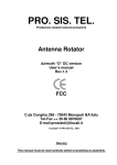
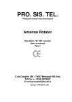
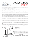
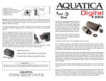
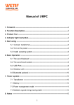
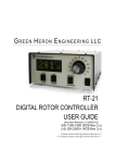
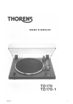
PRO. SIS. TEL. Produzione sistemi telecomunicazioni Antenna Rotator User’s manual Rev.1.2 C.da Conghia 298 - 70043 Monopoli BA Italy Tel-Fax ++ 39 80 8876607 E-mail:[email protected] Copyright ® PRO.SIS.TEL. 2011 Warning This manual must be read carefully before proceeding to assembly. Warranty 1) The rotator with the control box, hereinafter called “product”, or “rotator”, is warranted for 2 years from date of purchase, provided that it is supported by the document of sale issued by the manufacturer or authorized distributor. 2) The warranty covers replacement or repair of any defective component. 3) This warranty does not apply to product which have been subjected to misuse, negligence, accident, incorrect wiring performed by the user, improper installation or non-compliance to instructions furnished by us, damage to product which has been repaired or altered without authorization or to injury or loss resulting from careless maintenance. The warranty does not cover damage due to transportation and all causes not arising from defects in workmanship. 4) The warranty does not cover costs of transport or insurance for material returned to our workshops. 5) The manufacturer is not responsible for personal injury or property damage resulting from improper or careless use of the product. 6) All product is tested after assembly and is supplied without defect. We exclude the substitution or the prolongation of warranty for a possible damage. 7) After the 2 years warranty period, maintenance or repair will be subject to parts and labor charges. 8) No person is authorized to assume for us any liability in connection with the sale of our products. 9) This warranty does not cover damage to people or things due to misuse, improper or careless installation, or misunderstanding of instructions furnished by us. 10) The right of recession must be exercised in according to the law. 11) Our products are subject to continuous improvement. We reserve the right to implement improvements and changes without prior notification. 12) The legal code applying in MONOPOLI, Italy, will apply, in cases of dispute. 13) Purchasers of product are deemed to accept paragraphs 1, 2, 3, 4, 5, 6, 7, 8, 9, 10, 11, 12 and 13 as above. Model: PST S/N: Date of purchase: 2 Important Read this instruction manual carefully before attempting to operate the antenna rotator. Save this instruction manual. This instruction manual contains important safety and operating instruction for antenna rotator. Precautions ! WARNING, never connect or disconnect rotor cable or RS232 connectors while power is on. This may results in electrical shock or burn. Table of contents Section 1: Description; Section 2: Installation and use; Section 3: Principle of operation ; Section 4: Technical specifications; Section 5: RS232 remote control philosophy; Appendix 1: Declaration of conformity Table: Note: Last up-date 21 February 2011 3 Section 1 The controller 1-1 Front panel description. 1 - POWER SWITCH (POWER) Turns power ON and OFF 2 – Right lever: CW momentary switch Pushing and holding this switch will make the rotator turn clockwise If you have used the preset, or computer control to start rotation, you can over-ride those commands by momentarily depressing the switch. 3 – Left Lever: CCW momentary switch Pushing and holding this switch will make the rotator turn anti-clockwise If you have used the preset, or computer control to start rotation, you can over-ride those commands by momentarily depressing the switch. 4 - Display The display will show the current bearing in degrees. When the preset knob is turned, the display will show the preset bearing. The decimal points on the LED display blink * when you turn the target position knob on the front panel * rotation begins and is in progress * when rotation is complete. At that time the display will blink for the programmed delay time before further rotations are permitted. (Note - if the CW or CCW keys have been used, further rotations in the same direction are not subject to this delay time) The central decimal point will be ON when operate in “absolute” mode. The left decimal point will be ON when the rotator is operating in the CW extra range. The right decimal point will be ON when the rotator is operating in the CCW extra range. 5 - Preset rotating encoder To preset rotation, having 1 dergee step, turn the knob to the desired bearing. 3 seconds later, rotation towards the preset position will start, with the display showing the bearing as it changes. "Err" is displayed if the preset knob is turned to a position outside the rotation limits. 4 1-2 Rear panels description. 1 - DB9, RS232 female connector Enables connection to a PC RS-232 port for remote operation. Pin 5 = computer ground Pin 2 = serial data out (to computer data in) Pin 3 = serial data in (from computer data out) 2 - Rotators control cable connector Connects the rotator to the controller 3 – AC Power male socket (230Vac or 115 Vac) Connects the rotator to the controller 4 – Fuse holder. 19x5mm, 0.5A fuse is required. 1-3 Controller features. Warning: this is a complex controller, make sure you understand before using it. This controller has several features settable via RS232. Controller parameters settable via RS232 only: Soft start – Soft stop South stop or North stop Rotation range 360 or 500 Calibration Self-calibration Off-set Revers delay Preset delay PWM duty cycles Rotation range Optimizer Rotor chk Controller display mode settable manually only: Absolute or relative display mode. Entering in Absolute mode The absolute mode is usefull for controller calibration. In the absolute mode the display shows directly the rotator position expressed in absolute degrees: you read values from 000 to 500, the central decimal point ON means only that the controller is operating in “absolute” mode. In the other operational modes (north/south-stop) the absolute readings are converted into different angular position numbers, but only for input/display purposes: internally the program works with absolute angles. The absolute mode can be only entered turning-on the CBOX with the CW key pressed until the display shows a blinking “---“ (three minus): now you can release the key and the absolute mode is entered. You can move the motor using CW and CCW keys between the rotation limits. To exit from such a mode you must recycle CBOX power (forcing another mode by RS232 command isn’t effective). In the absolute mode the rotor can be only operated by the CW/CCW The bearing values in degree as shown by the display, are not absolute but relative, as show in the conversion tables: 5 Vdc 000 070 Deg. 110 east side outrange 180 S absolute values South stop 160 340 250 270 W South stop Vdc 000 070 Deg. 290 west side outrange 000 S 000 N 090 E North stop 500 180 S 240 west side outrange 430 500 relative values absolute values North stop 160 340 250 090 W 430 180 N 270 E 000 S 070 east side outrange relative values That mean when the pulses (Vdc=pulses) coming from the rotator encoder is 000, the display will show 110 deg. when in South stop (default) and will show 290 deg. when in North stop. With an applied pulses of 250 the display will show 000 deg when in South stop and and 180 deg when in North stop, while with an applied pulses of 500 the display will show 240 deg. when in South stop and 070 deg. when in North stop. Soft start and soft stop: A PWM is included. When it is in active it permits soft-start and soft-stop for the rotator. It doesn’t operate using CW or CCW paddle. Default valoue: included. South stop or North stop: Via RS232, it’s possible to switch the display reading mode. South stop means that rotation begin from south, pass trhought east, than north, then west and stop to south and viceversa. Nort stop means that rotation begin from north, pass trhought east, than south, then west and stop to north and viceversa. South stop is usual for HF antenna system. If you decide to switch to North stop, after than antenna is installed already, you will have antenna 180 degree off set, than you have to release the antenna mast clamps and manually rotate antenna for 180 degree to get new allignement. Default valoue: South stop. Rotation range 360: Even if 500 degrees is the potential rotation range, the true rotation is limited to 360 degree by limit switches. Note - Absolute values must be entered in the input fields. Default valoue: 070-430 Degrees (360 degree) Calibration If necessary, you can recalibrate your controller via RS232. See calibration procedure. Self-reallignement Each time rotator reach CCW end, if a misallignement being noticed, it will be automatically correct. Default valoue: ON Off-set If the initial antenna direction it’s not coincident with the geografic direction, you can set it via RS232. Default valoue: 0 Revers delay A reverse delay time is provided. This is to reduce stress on your rotator / tower and antenna systems caused by too-rapid reversal of direction. The default time is 3 seconds, but this may be altered in the software to suit your antenna system. 6 PWM duty cycles This feature controls the accelleration / deceleration of the rotator between rest and full rotation speed. This feature is kind to your antenna system as it gives smooth starting and stopping of your antenna. Rotation range This controller allow you to have programmable rotation range within 0-360 degrees. Rotor chk If implemented, if you select a target, the CPU will check the feeback signal from the rotator, and within 5 seconds will prevent the rotator from turning in the event of an abnormality. Default: Off Controller internal view Calibration procedure. Initial calibration is carried out in the factory Whenever if a recalibration is required (using the PC control program): Connect controller and PC via RS232. Power on the controller entering in Absolute mode. Run the tool software, open the calibration form, write in the Calibration set (F) window the calibration factor number that you find on the controller back panel and push the Calibration set button. Push CMD L button and check if the Calc Fact window show the same valoue. Recalibration is done. 7 1.4 The rotator The rotator has a unique design. The motor is located on the side of the machine. The motor output shaft terminates on a flange, where different kinds of mast clamp, available from us, may be fixed with bolts. Users may also supply their own clamp. On the motor side is located an IP67 seven-contact connector for motor power supply, encoder terminals, self-reallignement reed sensor. The encoder, used as the antenna position reader, is located on the DC motor driven by motor shaft. Limit switches will stop the rotation if CW or CCW limits being over passed. PST 110 - 71 - 61 PST2051 - 641 Rotator cable connector end 8 Section 2 Installation and connections 2.1 Unpacking After unpacking, immediately report any damage to the delivering carrier or dealer. Keep the shipping cartoon. 2.2 Power supply connection Connect the power cable and switch power on, display will show PHH and soon after 110. Switch power OFF. 2.3 Rotator control cable preparation & connection Before installing the rotator inside a tower, you need to prepare male connector for remote control cable, make all connections and test rotator operation throughly on the ground, as described below. Connect the rotator and control box with a 7-core control cable. Twisted and shielded cable is required. Two cores are used for the motor DC power supply, and four for the position reading encoder, one for the self-allignement reed sensor. If the diameter of the control cable is too thin, it will limit the voltage and reduce the torque. Do not use cable with less than 1 mm² of section area as DC motor power supply. Before connecting rotator and controller, make sure that power switch is OFF. Cable plug Wire no. 1 Wire no. 2 Wire no. 3 Wire no. 4 Wire no. 5 Wire no. 6 Wire no. 7 Motor terminals plug must be connected to must be connected to must be connected to must be connected to must be connected to must be connected to must be connected to 1 (VDC motor power) >= 1mm² 2 (VDC motor power) >= 1mm² 3 (+5VDC encoder input) 4 0 Vdc encoder lead/GROUND) 5 (encoder lead A) 6 (encoder lead B) 7 (self-allignement) Warning: Improper wiring can result in damage to the rotator circuitry when the power is swiched on. THIS IS NOT COVERED BY THE WARRANTY. 2.4 Rotator cable inspection Ensure the cable is correctly wired before connecting it to the controller. 2.5 Preinstallation check ! Warning, use only CW and CCW switch while preinstallation check is in progress. Switch power ON, display will show PHH and after than the rotator position. Fully depress the CW lever switch for 1-2 seconds. the rotator should start to move in the CW direction. Release the switch and try the same test for CCW. The opposite rotation will be a little delayed by the preset delay time, which is normal. Note the controller display during this test. The readout should increase for CW and decrease for CCW. If these tests give incorrect results, refer to the troubleshooting section of this manual. If the results are correct, test full rotation to the electronic limits in both CW and CCW directions. When this test has been performed turn the rotator to 000 degrees with the leverl switches. Then test the preset feature by setting a new direction with the preset knob. Observe that the rotator will turn to that position and stop. The optimiser feature will ensure that travel to the preset position is always in the shortest manner. 9 2.6 Troubleshooting - Power - Check the presence of the house power at power outlet; - Check that the power cable plugs is correctly connected. - Check the fuse. If it’s blown, replace it with one of the correct value and switch power on. If it blows again, the user contacts the local service agent. - Motor turns in the wrong direction If while you were pushing CW switch the rotator started in counter clock wise sense, then the motor is getting reversed DC polarity. Change over the motor wires. - Rotator follow the right CW and CCW commands but display show the opposite. the controllerr is getting reversed encoder pulses. Change over the encoder wires. - Rotator follow the right CW and CCW commands but display don’t change. - With a digital voltmeter, check the presence of +5Vdc on the motor board, lead no. 4 If +5Vdc is not there, check the rotator cable connections/continuity. 2.7 Rotator installation This rotator is designed to be installed inside a tower, make sure that your antenna mast charge antenna load and rotate trought a trust bearing. This will make you life easy in case of rotator failure. Before drilling holes in the mounting plate, place the rotator inside the tower and adjust its position so that there will be no interference between rotator body and tower. Put the antenna mast inside the mast clamp and lock centrally. The centre axis line must be within 0.5° of true. By a pen, mark the position of the mounting holes on the mounting place, remove the rotator, and drill the holes . Use the four bolts with washers and self-locking nuts to secure the rotator on the mounting plate. Before tightening the bolts, insert the antenna mast in mast clamp, turn the rotator for 1 revolution and adjust its position until the central axis line is within 0.5° . Now tighten the bolts. Note: Keep you rotator base dry, make sure that your tower rotator plate has enough dreinage holes. Your rotator could get moisture in the base bell from the water standing on the plate. If your tower rotator plate doesn’t have drainage holes and you can’t drill some, than put some washers between the rotator base and the tower rotator plate. 2.8 Antenna direction adjustement Antenna rotator alignement is mechanical. After the antenna is installed on the mast, turn rotator to the desired bearing. Unlock the bolts on mast clamp and with a magnetic compass turn the antenna mast until the antenna beam direction is like that shown on the rotator control box. Lock the antenna mast with the mast clamp bolts. The antenna beam direction now is fixed. If you want to change it, you must rotate the antenna clamp on antenna mast. 2.9 Rotator maintenance The worm-geared motors are lubrificated for life and no maintenance is required. If you live in an industrial zone or sea area, after a time you may have some corrosion to the outer casing. Rotators are coated with anticorrosive paint at the factory and if repainting is necessary, use ordinary anticorrosive paint for ferrous metal. An IP67 connector is provided for rotator connection. 10 Section 3 Principles of operation 3.1 Rotator The rotator is manufactured with a worm-wheel geared motor drived by a high torque dc motor.This method, normally used in heavy duty industrial and professional machinery, permits a very high reduction ratio, with high power torque with both low power motor drive and high brake torque, due the self-braking property of the worm-wheel geared motor. 3.2 Electrical configuration 3.2.1 Indicator circuit Three digit, 7 segments led display are used for the direction indicator and the antenna direction is displayed in degrees. 3.2.2 Motor power switch The motor is powered throught two 10 Amps long life relais. Limit switches are provided in the bottom basement. 115V 60Hz AC FILTER 1 + DC MOTOR DISPLAY POWER CPU INPUT 230V 50Hz TRANSF POWER SUPPLY 0-24Vac M VDC 2 - + HALL A ENCODER B 0-9Vac + A B CW - CCW ROTATOR RS232 PRO.SIS.TEL. C.da Conghia 298 70043 Monopoli BA tel.- fax ++39 080 8876607 www.prosistel.it DRAW: Pro-working basical block diagram S/N: A007 REV: 3 DRAWN BY: Capitanio Piero DATE: July, 26/2006 11 Section 4 Specifications 4.1 Worm gear box The worm gear box has a waterproof aluminium case conforms to the CEE 89/392/CEE standard. 4.2 Motor The motor, in a steel waterproof case conforms to CE rules. 4.3 Control unit Microprocessor controlled digital readout display having RS232 built inside. The controller has ferrous parts painted. Conform to CE and FCC rules. Rotators Specifications METRICS Model Wind area m2 Motor torque Kg/cm Brake torque Nm Vert. load Kg Rotor speed 360° Variable speed Rotation range PST 641D 1.2 1.000 400 450 ± 60” yes 360 12 Vdc 5 digital yes yes 10 PST 2051D 2.5 2.000 600 650 ± 60” yes 360 12 Vdc 5 digital yes yes 14 PST 61D 3.9 3.800 1.180 850 ± 90” yes 360 12 Vdc 5 digital yes yes 25 PST 71D 8.8 6.000 2.172 1.000 ± 120” yes 360 24 Vdc 5 digital yes yes 35 PST 110D 10 6.000 3.400 1.200 ± 150” yes 360 24 Vdc 5 digital yes yes 45 Wind area Sq.ft Motor Torque Lbs ft Brake torque Lbs ft Vert. load Lbs Rotor speed 360° PST 641D 12 73 703 990 ± 60” yes 360 12 Vdc 5 digital yes yes 22 PST 2051D 25 147 1.000 1.430 ± 60” yes 360 12 Vdc 5 digital yes yes 31 PST 61D 39 280 2.100 1.870 ± 90” yes 360 12 Vdc 5 digital yes yes 55 PST 71D 88 1.032 4.032 2.200 ± 120” yes 360 24 Vdc 5 digital yes yes 77 PST110D 100 1.032 6.050 2.200 ± 150” yes 360 24 Vdc 5 digital yes yes 110 Motor Wires Redout RS232 Preset Kg Volts N. US/UK Model Variable Rotation speed range Motor Volts Wires Redout RS232 Preset Lbs N. Note: It is a good practice do not overpass the 50% of the maximum rotator wind load. 12 Section 5 With this user’s manual a CD is provided. CD contains several folders in which there are some files with some extra informations about your antenna rotator, as a copy of this manual as well. We suggest you pay attention on such extra informations, from which you can learn more about this antenna rotator, but in mean time they are intended for expert technicians, so make sure to well undestand what you are reading before to do anything. RS232 philosophy.pdf This file contains extensive informations about the RS-232 door, as communication protocol/instructions, full calibration procedure and more, as well. If you are software expert with such informations you can develope a rotator software drive by yourself. If your favorite log software still doesn’t have a drive for your new D controller, copy this file to your log software writer, asking him to write a D drive in his log software. Please read it carefully. RotorVxxx.exe (tool software) This executable software allows you to change your rotator parameters to suit your personal choice. It is intended as a tool rather than a program to control the rotator remotely. Be very careful using the program and ensure that you are competent to make changes before making them. If running it you get all windows filled with question marks, means that software missed the COM door, fix it before to continue. Insert the CD in your computer, open folder named “setup”, run “set up” file and follow instuctions step by step. Service issues raised by incorrect use of the software are not covered by the warranty RotorVxxxReadme.pdf This file contains extensive information and instruction about the use of the “RotorVxxx.exe” tool software. Please read it carefully. Rotor.ini This file contains the COM port number. If you need to use a COM port number that is not included in the software tool, open this file, overwrite in there the COM port number and save it. Dear customer, thank you for purchase a Pro.Sis.Tel./BigBoyRotators, if you are happy with it please talk to everybody, if you are unhappy with it please talk with us. Your feed back and suggestions, will be very appreciated, to improve our products. Annamaria Fiume IK7MWR MADE IN ITALY Protect your environment, in case of discontinuing of this unit, consign it to specialized metal waste collector. 13 Appendix 1 DICHIARAZIONE DI CONFORMITA’ DECLARATION OF CONFORMITY according to EN45014: 1998 CE Si dichiara che il prodotto: Rotore d’antenna mod. PST110D è conforme ai requisiti essenziali delle seguenti direttive comunitarie: This product: Antenna rotator model PST110D is fully conforms to the council directives: - 89/336/CEE 92/31/CEE 93/68/CEE marcatura CE per prodotti destinati ad essere utilizzati entro taluni limiti di tensione 93/97/CEE 73/23/CEE recepite dai seguenti decreti legislative as amended by italian law. - Nr. 791 del 18/10/1977 attuazione 73/23 Nr. 615 del 12/11/1996 recepimento direttive 92/31/CEE, 93/68/CEE, 93/97/CEE Nr. 626 del 25/11/1996 attuazione della direttiva 93/68/CEE Nr. 277 del 31/07/1997 modifiche alla Nr. 626 del 25/11/96 E’ conforme ai requisiti di prodotto indicati dalle seguenti norme armonizzate: It is conforms to product’s requirements as indicate in the following armonized rules: - CEI EN 50082-1 Compatibilità elettromagnetica, norma generica sull’immunità. Ambienti residenziali, commerciali ed industria leggera. CEI EN 50081-1 Compatibilità elettromagnetica, norma generica sull’emissione. Parte 1, ambienti residenziali, commerciali e dell’industria generica. CEI EN 60335-1 Sicurezza degli apparecchi elettrici d’uso domestico e similare. Parte 1, norme generali. Esso è certificato FCC classe B. It is class B FCC certified. In fede Annmaria Fiume Monopoli lì, 01/07/2010 14 PST641: 4 1/2" (ø115mm) PST2051: 5 1/8" (ø130mm) ø10mm 3/8" ø12mm 1/2" PST61 - 71: 6 1/2" (ø165mm) PRO.SIS.TEL. C.da conghia 298 70043 Monopoli BA ITALY www.prosistel.it DRAW: Rotor plates holes diagram Note – this drawing is not to scale 15 16 C.da Conghia 298 70043 Monopoli BA ITALY tel. ++39 080 8876607 www.prosistel.it a1 PST641 280 PST2051 298 PRO.SIS.TEL. a2 70 80 b2 90 95 d 115 130 h 170 186 Checked by: Date: May 05/2004 Note: measurements in mm Drawn by: Capitanio Piero Scale: 1:1 Rev: Draw: PST641-2051 general dimensions b1 150 175 Fixing plate down view Fixing plate down view PRO.SIS.TEL. C.da Conghia 298 70043 Monopoli BA ITALY tel. ++39 80 8876607 Draw: PST61D, general dim. Scale: 1:1 Drawn by: Capitanio Piero Serial number: Date: Feb 02/2007 Checked by: Rev: Note: measurements in mm Fixing plate down view PRO.SIS.TEL. C.da Conghia 298 70043 Monopoli BA ITALY tel. ++39 80 8876607 Draw: PST71DC general dimensions Scale: 1:1 Drawn by: Capitanio Piero Serial number: Date: April 09/2008 Checked by: Rev: Note: measurements in mm 18 Company: Pro.Sis.Tel. Draw: PST110D-Dimensions Date: Sept. 03/2010 Rev: Note: Quotes in millimeters 19 COMPANY: PRO.SIS.TEL. DRAW: MastClampConfiguration MATHERIAL: Fe360 zinc plated DATE: Sept. 03/2010 A1- Bolt, stainless steel, M10x40mm A2- Washer ø10mm, stainless steel A3- Mast clamps 3”, zinc galvanized steel A4- Split washer ø8mm, stainless steel A5- Bolt, stainless steel, M8x100mm x6 A6- Stainless steel nut, M8 A7- Rotator shaft with plate, zinc galvanized steel A8- Split washer ø10mm, stainless steel A9- Nut M10, stainless steel x4 x4 x2 x6 x6 x1 x4 x4 21 Appendix 2 Warning Protect your equipement The rotator and controller are electronic devices containing sensitive components that could be damaged from lightning, heavy electrostatic charges or electric fields or something else. Make sure to disconnect rotator cable from the controller and controller power cord when not used as you do with your coax cables when a tunder storm is approaching. Pay attention, Protect your equipement because if happens it isn’t covered by the warranty.