1
Application Note
Start-up of the phyCORE-ARM7/AT91
Development Kit (PCM-014)
This Application Note provides instructions on how to run an example
program on the phyCORE-ARM7/AT91, mounted on the PHYTEC
Development Board, in conjunction with the freeware
OCD-Commander utility program and the PHYTEC JTAG adapter
(JA-001).
Please refer to the phyCORE-ARM7/AT91 hardware manual for
specific information on such board-level features as jumper
configuration, memory mapping and pinout.
1
System Description
1.1 Hardware Description
The following hardware components are necessary for start-up of the
phyCORE-ARM7/AT91:
• phyCORE-AT91M55800A with 2.0 mm JTAG connector at X2
(part number PCM-014-23111-D)
• Development Board HD200 5V (PCM-997-V2)
• 5V DC power supply
• JTAG Adapter (JA-001)
• JTAG-Emulator Adapter (JA-002)
• parallel DB-25 cable
All hardware components are included in the phyCORE-ARM7/AT91
Development Kit, for example KPCM-014-23111-D.
PHYTEC Technologie Holding AG 2003
Europe: Support Hotline: +49 (6131) 9221-31 http://www.phytec.de
North America: Support Hotline: + 1-800-278-9913 http://www.phytec.com
LAN-026e_2
1/16
Application Note
1.2 Software Description
This Application Note for the phyCORE-ARM7/AT91 requires the
following software tool:
• Macraigor OCD-Commander
This freeware program can be found on the phyCORE-ARM7/AT91
Tool-CD (included in the Rapid Development Kit) under
\Tools\OCD_Commander.
It
is
also
downloadable
at
www.macraigor.com.
2
Getting Started
2.1 Interfacing the phyCORE-ARM7/AT91 to a Host-PC
Connecting the phyCORE-ARM7/AT91, mounted
Development Board, to your computer is simple:
on
the
• If the phyCORE module is not already pre-installed, mount it pinsdown onto the Development Board’s receptacle footprint (X6) as
shown in the figure below. Ensure that pin 1 of module, designated
by the hash stencil mark, matches pin 1 of the receptacle on the
Development Board.
Ensure that there is a solid connection between the module’s pins and
the Development Board receptacle. Also take precautions not to
damage the connectors when the phyCORE is removed from and
inserted onto the Development Board.
PHYTEC Technologie Holding AG 2003
Europe: Support Hotline: +49 (6131) 9221-31 http://www.phytec.de
North America: Support Hotline: + 1-800-278-9913 http://www.phytec.com
LAN-026e_2
2/16
Application Note
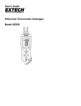
• Ensure proper jumper settings on the phyCORE Development
Board as shown in Figure 1.
Figure 1:
Default Jumper Settings of the phyCORE Development
Board HD200 with phyCORE-AT91M55800A
• Connect the PHYTEC JTAG-Emulator Adapter JA-002 adapter to
the phyCORE-AT91M55800A module by putting the receptacle
connector X3 on JA-002 onto pin header rows X2 on the
phyCORE module. Make sure that pin #1 (denoted by the hash
stencil mark on the PCB) of X3 on JA-002 is correctly connected
to pin #1 on JTAG connector X2 (black pad on the connector side
of the PCB, refer to Figure 2) of the phyCORE-AT91M55800A.
PHYTEC Technologie Holding AG 2003
Europe: Support Hotline: +49 (6131) 9221-31 http://www.phytec.de
North America: Support Hotline: + 1-800-278-9913 http://www.phytec.com
LAN-026e_2
3/16
Application Note
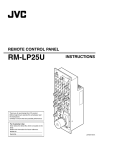
JTAG-Connector X2
Figure 2:
JTAG Connector X2 on the phyCORE-AT91M55800A (Bottom View)
• Now plug the 20-pin connector (2.54 mm spacing) at the end of the
JTAG adapter (JA-001) flat band cable into connector X2 on the
JA-002 adapter. Make sure that pin 1 (red cable) of the JA-001
flat-band cable is correctly attached to pin 1 of the header
connector at X2 of JA-002.
PHYTEC Technologie Holding AG 2003
Europe: Support Hotline: +49 (6131) 9221-31 http://www.phytec.de
North America: Support Hotline: + 1-800-278-9913 http://www.phytec.com
LAN-026e_2
4/16
Application Note
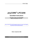
Figure 3:
JA-001 and JA-002 Connected to the phyCORE Module
• Connect the 25-pin end of the JTAG adapter (JA-001) to the
parallel port of your host-PC using the included DB-25 cable.
• Make sure that the mode of the parallel port on your host-PC is set
to ’EPP’. Configuration of the EPP mode must be done in the BIOS
setup of the host-PC by selecting the <F1> function key1 while the
operating system is booting up.
1
:
The function key used to enter the System BIOS depends on the target computer system.
Please consult your User’s Manual for details.
PHYTEC Technologie Holding AG 2003
Europe: Support Hotline: +49 (6131) 9221-31 http://www.phytec.de
North America: Support Hotline: + 1-800-278-9913 http://www.phytec.com
LAN-026e_2
5/16
Application Note
• This will result in appearance of the following BIOS menu prior to
start-up of Windows:
BIOS Configuration Main Menu
Select a Menu
System Information
Video Information
Disk Drives
>Input/Output Ports
Power Management
Startup Options
Model Information
Date and Time
Advanced Options
↑/↓/←/→/<CR>/<TAB> to select or <PgUp>/<PgDn>/+/− to modify
<ESC> to return to Main Menu
• Use the up ↑ and down ↓ arrows on your keyboard to select
"Input/Output Ports" using the <ENTER> key.
• This advances you to the "Input/Output Ports" menu. Depending
on the version of BIOS installed on your host-PC, this window
should appear similar what is shown below. Use the up ↑ and
down ↓ arrows on your keyboard to select "EPP" or "Enhanced
Parallel Port" under the parallel port. This will configure your
parallel port for bi-directional communication, which is required to
operate the phyCORE-ARM7/AT91 target hardware using the
JA-001 Wiggler circuitry and the OCD-Commander tool.
PHYTEC Technologie Holding AG 2003
Europe: Support Hotline: +49 (6131) 9221-31 http://www.phytec.de
North America: Support Hotline: + 1-800-278-9913 http://www.phytec.com
LAN-026e_2
6/16
Application Note
Input/Output Ports Menu
Serial Port
Base Address
IRQ
[Enable]
[xxxxx]
[xxxxx]
Parallel Port
Base Address
IRQ
Operation Mode
ECP DMA Channel
.
.
.
[Enable]
[xxxxx]
[xxxxx]
[ EPP ]
[-]
Note:
There are three standard parallel port settings supported in BIOS. The
default value is Normal (SPP), which is the slowest transfer mode
designed for output communication (such as to a printer). There are
two faster bi-directional modes available - the ECP (Extended
Capabilities Port) and EPP (Enhanced Parallel Port) modes. ECP uses
the DMA protocol to achieve data transfer rates of up to
2.5 MBit/s and provides symmetric bi-directional communication.
EPP uses existing parallel port signals to provide asymmetric bidirectional communication and is required by most programming
devices that frequently switch input/output directions.
• Select the <ESC> key as required to exit out of the BIOS menu
structure and resume boot-up of Windows.
PHYTEC Technologie Holding AG 2003
Europe: Support Hotline: +49 (6131) 9221-31 http://www.phytec.de
North America: Support Hotline: + 1-800-278-9913 http://www.phytec.com
LAN-026e_2
7/16
Application Note
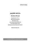
• Using the included 5V DC power adapter, connect the power
socket X1 on the phyCORE module to a power supply (refer to
Figure 4 for the correct polarity).
Polarity:
+5 VDC
≥ 500 mA
Center Hole
1.3 mm
-- +
3.5 mm
GND
Figure 4:
Power Connector
• The red power LED D2, located next to the power socket at X1,
should light. This indicates that proper voltage is supplied to the
phyCORE / Development Board combination (which is also
referred to as "target hardware" within this document).
The phyCORE-ARM7/AT91 should now be properly connected via
the Development Board to a host-PC and power supply. You are now
ready to use the OCD-Commander to establish communication
between the host-PC and target hardware.
2.2 Installing the OCD-Commander Software
The Macraigor Systems OCD-Commander is a freeware utility
program used for downloading application code to a target hardware
platform and demonstrating basic debugging features. This software is
included
on
the
Tool-CD
accompanying
the
phyCORE-AT91M55800A Rapid Development Kit or can be
downloaded at www.macraigor.com.
• Insert the PHYTEC Tool-CD into your host-PC’s CD-ROM drive.
• Browse to the \Tools\OCD_Commander folder.
• Run the ocd_dbgr.exe program.
PHYTEC Technologie Holding AG 2003
Europe: Support Hotline: +49 (6131) 9221-31 http://www.phytec.de
North America: Support Hotline: + 1-800-278-9913 http://www.phytec.com
LAN-026e_2
8/16
Application Note
• The following pop-up window will appear.
• Click on Yes to continue installation.
• The OCD Commander Setup installation wizard will start and the
following Welcome window will appear:
• Click on Next and follow the instructions given in the setup
windows.
PHYTEC Technologie Holding AG 2003
Europe: Support Hotline: +49 (6131) 9221-31 http://www.phytec.de
North America: Support Hotline: + 1-800-278-9913 http://www.phytec.com
LAN-026e_2
9/16
Application Note
• At the end of the software installation you will be prompted to
restart your computer. Make sure all other applications are shut
down and restart your system.
You have now successfully installed the OCD Commander on your
computer.
PHYTEC Technologie Holding AG 2003
Europe: Support Hotline: +49 (6131) 9221-31 http://www.phytec.de
North America: Support Hotline: + 1-800-278-9913 http://www.phytec.com
LAN-026e_2
10/16
Application Note
2.3 Launching the OCD-Commander
• Reset the target hardware by pressing the Reset button at S2 on the
Development Board. Release the button after holding it for one or
two seconds.
Note:
Failure to reset the target hardware prior to connection with the
OCD-Commander tool will result in incorrect operation!
• Launch the OCD-Commander. Starting this utility program should
result in the following terminal window:
PHYTEC Technologie Holding AG 2003
Europe: Support Hotline: +49 (6131) 9221-31 http://www.phytec.de
North America: Support Hotline: + 1-800-278-9913 http://www.phytec.com
LAN-026e_2
11/16
Application Note
The CONNection Dialog… window should also appear when starting
the OCD-Commander. If this window does not appear automatically,
it can be invoked using the Commands pull-down menu. All
commands can be accessed from the top of the OCD-Commander
window; either via pull-down menus or by clicking the available
buttons ("reset", "step", "go"… "macro"). Additional status display
bars will appear below the Command field providing information
about the current connection and target system.
• Set the following connection parameters within the CONNection
Dialog… window:
"ARM" and "ARM7xx" as Target Processor
"Wiggler" as the OCD-Interface Device
"2" as OCD Speed
• Also ensure that the correct parallel port parameter is selected for
your system. This example uses LPT port #1.
• Click OK to save these settings.
You should now have a connection to the ARM7 target hardware.
Confirm this by looking at the "Target Status" panel at the bottom of
the OCD-Commander window, which should indicate that "Wiggler
on LPT1" communication has been established.
PHYTEC Technologie Holding AG 2003
Europe: Support Hotline: +49 (6131) 9221-31 http://www.phytec.de
North America: Support Hotline: + 1-800-278-9913 http://www.phytec.com
LAN-026e_2
12/16
Application Note
• Click the "Macro" button on the top of the OCD-Commander
window. A new dialog box will appear. This enables you to select
a macro to configure the applicable Chip Select and other registers
of the AT91M55800A that populates the phyCORE-ARM7/AT91
with the correct values and wait states required for the demo
programs provided by PHYTEC.
• Select the "AT91M55800A" macro located in the:
../Tools/OCD_Commander/Macro/ folder on the included
PHYTEC Tool-CD.
The macro will automatically load and yield the following in the
OCD-Commander terminal window. Loading and execution of the
macro can be viewed in the center portion of the OCD-Commander
window, which is a terminal program that displays communication
between the host-PC and PHYTEC target hardware.
PHYTEC Technologie Holding AG 2003
Europe: Support Hotline: +49 (6131) 9221-31 http://www.phytec.de
North America: Support Hotline: + 1-800-278-9913 http://www.phytec.com
LAN-026e_2
13/16
Application Note
The "endian little" message will appear in the Command field. This
refers to how binary values are represented. All processors must be
designated as either big endian or little endian. A "little endian"
representation (used by Intel processors and many others) has a
multibyte integer value with its least significant byte stored at the
lowest memory address (little end first). A "big endian" representation
(mostly used by Motorola processors), on the other hand, places the
most significant byte at the lowest memory address. The ARM7 compatible AT91M55800A - processor uses "little endian"
representation.
After running the phyCORE-specific macro you are now ready to
download a machine-readable *.elf file to the target hardware from
your host-PC using the JTAG connection.
PHYTEC Technologie Holding AG 2003
Europe: Support Hotline: +49 (6131) 9221-31 http://www.phytec.de
North America: Support Hotline: + 1-800-278-9913 http://www.phytec.com
LAN-026e_2
14/16
Application Note
• Now click on the Commands pull-down menu and select
Download.
• A new dialog box will appear. Here you can choose an object file
for download.
• Navigate to the folder
PCM-014\Examples\HighTec_Gnu\RAM\Blinky\objsn on the
PHYTEC Tool-CD and select the Blinky.elf file for download.
• Click on the Open button to start the download of the Blinky
application.
• Download of the file can be viewed within the terminal window.
Successful download of the Blinky.elf file will result in the
following text appearing in the terminal window.
>DOWNLOAD
...
PC set to starting address 0x04000060
Blinky.elf: downloaded 5692 bytes
1.264 seconds
in
0
minutes,
PHYTEC Technologie Holding AG 2003
Europe: Support Hotline: +49 (6131) 9221-31 http://www.phytec.de
North America: Support Hotline: + 1-800-278-9913 http://www.phytec.com
LAN-026e_2
15/16
Application Note
Please note that the download time will differ from system to system.
• Click on the "go" button at the top of the OCD-Commander
window to execute the Blinky.elf demo file that has been
downloaded to the target hardware. Proper execution of the demo
program will turn the programmable LED D3 on and off at regular
intervals.
To get help, type ’help’ in the command line of the OCD-Commander
and press <Enter>. Clicking on other commands such as "reset",
"step" and halt enables debugging of the code.
PHYTEC Technologie Holding AG 2003
Europe: Support Hotline: +49 (6131) 9221-31 http://www.phytec.de
North America: Support Hotline: + 1-800-278-9913 http://www.phytec.com
LAN-026e_2
16/16