1
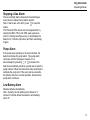
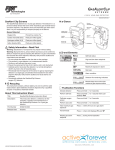
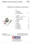
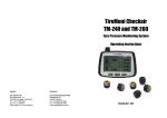
NH3 RESPONDER
Portable Ammonia Leak Detector
QUICK REFERENCE GUIDE
NH3 RESPONDER
Operating Manual
Specially configured
GasAlert Micro 5 PID
from
Refer to Operating Manual for more details.
Manual provided on CD with unit at
time of purchase
2
NH3 RESPONDER
Operating Manual
Table of Contents
Getting Started ……………………………………. 4
Activating the Detector………………………… 6
Self-Test ………………………………………... 6
Deactivating the Detector …………………….. 6
User Options Menu ………………………………. 6
Options Menu …………………………………. 6
Backlight …………………………………….. 7
Confidence Beep …………………………… 7
Due-Lock ……………………………………. 7
Latched Alarms …………………………….. 7
Passcode Protect ………………………….. 7
Safe Display ………………………………… 7
Fast Pump ………………………………….. 7
Sensor Configuration ……………………….… 8
Sensor Enable/Disable…………………….. 8
Span Gas Value…………………………….. 8
Correction Factor…..……………………….. 9
Datalogger………….….……………………….. 9
Alarms……………………….…………………. 10
Viewing Gas Exposures …………………….. 10
Clearing Gas Exposures ……………………. 10
Gas Alarm Setpoints ………………………… 10
Viewing the Alarm Setpoints ……………….. 10
Stopping a Gas Alarm ………………………. 11
Pump Alarm ………………………………….. 11
Low Battery Alarm……………………………. 11
Calibration and Setting Alarm Setpoints ……... 12
Guidelines ……………………………………. 12
Calibration Procedure ……………………….. 12
Maintenance …………………………………….. 14
Replacing the Batteries ……………………... 14
Replacing a Sensor ………… ………………. 14
Cross Sensitivity and Contamination…….……. 15
Troubleshooting ………………………………… 16
Specifications …………………………………… 17
Warranty…………………………………………..18
Calibration Technologies
866-394-5861
920 N. Trade Winds Pkwy, Columbia, MO 65201
3
NH3 RESPONDER
Operating Manual
Getting Started
The NH3 Responder detector is especially configured
for ammonia response operations. It utilizes two sensor
technologies to cover the ranges of interest in an
ammonia response operation. The first sensor is a PID
sensor, which is configured to display ammonia
concentration readings in the range of 0-1000 ppm.
Over 1000 ppm this sensor displays OL and the LEL
sensor is configured to display %LEL readings for the
explosive levels decision making range. (10% LEL =
16,000 ppm NH3)
Additionally, the PID sensor has an extremely fast
response time and is useful for finding small ammonia
leaks. Think of it as an “electronic sulfur stick” for
locating difficult to find leaks by “sniffing” around valve
packing, sight glasses, shaft seals, etc.
4
NH3 RESPONDER
Operating Manual
Table 1. Pushbutton Operations
Pushbutton
Description
•
To turn on the detector press
•
To turn off the detector, press and hold
operation only).
.
•
To increment the displayed value or scroll up, press
•
To enter the user options menu, press
is complete.
•
To clear the TWA, STEL, and MAX gas exposure readings, press
and hold until the countdown is complete.
•
To view the date and time, alarm setpoints (TWA, STEL, low, and high) of all sensors, and the
LEL/PID correction factor, press
.
•
To decrement the displayed value or scroll down, press
.
•
To initiate calibration and setting alarm setpoints, press
until the countdown is complete.
and
•
•
To view the TWA, STEL, and MAX hold readings, press
To acknowledge latched alarms press
.
.
until the countdown is complete (from normal
and
.
simultaneously and hold until the countdown
and
simultaneously
simultaneously and hold
5
NH3 RESPONDER
Operating Manual
Activating the detector
To activate the detector press
.
Self-Test
Once the detector is activated, it performs self-tests on
the sensors, battery, audible visual alarms and circuit
integrity.
Note: During the pump test the unit will prompt you
to block the inlet to the pump. Create a tight seal
with your finger over the inlet until the block-inlet
test is complete (approx 5 seconds).
Deactivating the detector
To deactivate the detector, press and hold
while it
beeps and flashes to the corresponding countdown. At
the end of the countdown the detector emits an
extended beep and flash, and displays 0 before
deactivating.
User Options Menu
If the detector is passcode protected, a passcode must
be entered to access the user options menu. For more
information, refer to Passcode Protect.
The available user options are as follows:
1. Exit
2. Options: backlight, confidence beep, due-lock,
latch, passcode, safe, and fast pump;
3. Sensors: sensor enable/disable, span gas, STEL
period, TWA method, resolution, % vol CH4,
correction factor, and automatic O2 calibration;
4. Logger
5. Clock
6. Language: English, French, German, Spanish, and
Portuguese;
To enter the user options menu, press and hold
and
simultaneously as the detector beeps and flashes to
the corresponding countdown.
Options Menu
Each feature within the Options menu is enabled or
disabled by pressing
to toggle the checkbox.
6
NH3 RESPONDER
Operating Manual
Backlight
The backlight (Backlght) option is used to enable the
LCD backlight to activate automatically in low-light
conditions. If disabled, the backlight is activated only
when the detector is in alarm mode. The detector is
shipped with the backlight option enabled.
Confidence Beep
The confidence beep (Confibeep) option is used to
provide continuous confirmation that the detector is
operating properly. When confidence beep is enabled,
the audible alarm beeps once every 10 seconds. The
detector is shipped with the confidence beep option
disabled.
Due-Lock
If Due-lock is enabled and a sensor is overdue for
calibration upon start-up, the passcode must be entered
to access normal operation. If the correct passcode is
not entered, the detector deactivates. The detector is
shipped with the due-lock option disabled.
Latched Alarms
Passcode Protect
The passcode option is used to prevent unauthorized
access to the user options menu, the calibration
function, and to adjusting the alarm setpoints.
Note: The passcode is provided separately.
If passcode protect is enabled and the Enter
passcode: 1000 screen displays, press
or
to
scroll to the correct passcode and then press
to
confirm. The detector is shipped with the passcode
protect option disabled.
Safe Display
When enabled, the safe option confirms that normal
ambient conditions prevail and there are no gas hazards
present. When all gas levels are normal or below the
alarm setpoints, Safe displays continually on the LCD.
The detector is shipped with the safe option disabled.
Fast Pump
If the sampling hose is longer than 50 ft., the Fast
pump option must be enabled for maximum flow rate.
The detector is shipped with the fast pump option
disabled. If enabled, the battery life will deplete sooner.
If enabled, the latched alarms (Latch) option causes the
low and high gas alarms (audible, visual, and vibrator)
to persist until they are acknowledged. Press
to
acknowledge the alarm. The detector is shipped with
the latch option disabled.
7
NH3 RESPONDER
Operating Manual
Sensor Configuration
The Sensor options provide access to additional
options and functions that are available for each sensor.
Depending upon the sensor that is selected, some or all
of the following options are available for configuration:
• enabling/disabling a sensor
• setting the span gas value
• adjusting the STEL period (not applicable to LEL
sensor)
• resolution setting (not applicable LEL sensor)
• % vol CH4 (LEL sensor only)
• Selecting the correction factor
For all sensor options, if a value is changed but not
confirmed within 5 seconds, the detector emits an
audible alarm and displays the following error message.
The detector retains the previous value and returns to
the user options menu.
Sensor Enable/Disable
If a sensor fails, disabling the sensor deactivates the fail
alarm. The sensor should be replaced and enabled as
soon as possible. The detector will function normally
with the remaining enabled sensors. If a sensor is
enabled but it is not installed in the detector, FAIL
displays above the gas bar of the missing sensor.
8
Span Gas Value
The Span gas option is used to increase/decrease the
gas concentration level for calibration. The following
span gas values are set to match the recommended
calibration gas concentrations. Do not change without
first contacting Calibration Technologies.
• PID sensor: 23 ppm Ammonia
• LEL sensor: 2.5% Methane
Note: See page 12 for recommended calibration gas.
STEL Period
The detector is shipped with the STEL calculation
period set to 15 minutes.
TWA Method
The TWA method is used to select either the OSHA or
ACGIH calculating method.
OSHA Method: 8 hour moving average.
Resolution
This option is used to display the gas measurement
using Regular or Extra resolution.
Note: LEL and PID sensors do not have resolution
settings.
NH3 RESPONDER
Operating Manual
% Vol CH4 (LEL Sensor Only)
Datalogger
Correction Factor (CF)
The MMC/SD card (located underneath the battery
pack) is automatically formatted during the startup selftest and becomes active.
If the % vol is enabled, any currently enabled correction
factor is ignored and the detector operates assuming a
methane (CH4) calibration. The detector is shipped
with %vol disabled.
LEL Sensor
Note: The sensor is shipped with the correction factor
set for ammonia (0.8).
This option is used to enter compensation factors for
hydrocarbons other than methane. The factor can only
be applied if the LEL sensor has been calibrated with
methane.
PID Sensor
Note: The sensor is shipped with the correction factor
set for ammonia.
This option is used to enter compensation factors for
selected gas types.
The Logger option is used to define how often the
detector records a datalog sample (once every 1 to 127
seconds). The datalogger records information that can
be compiled to create a report.
The datalog files can be downloaded from the MMC/SD
card into most spreadsheet applications using a card
reader.
To view a datalog file, deactivate the NH3 Responder
and remove the SD card. Insert the card into a card
reader and open the LOGFILE0.csv file.
Storage: 500,000 lines of data available; 4.4 months at
5 second intervals (based on a normal work week).
Memory type: Wrap-around memory ensures most
recent data is always saved.
Approved MMC and SD cards: 128 MB Delkin SD card
and 64 MB Unigen SD card
9
NH3 RESPONDER
Operating Manual
Alarms
If more than one type or level of alarm exists
simultaneously, a multi-gas alarm will result. To change
the factory-set alarm setpoints, refer to Calibration and
Alarm Setpoints. During an alarm condition, the detector
activates the backlight and displays the current ambient
gas reading.
Viewing Gas Exposures
Press and hold
until the
MAX gas exposures screen displays.
The TWA gas exposures display next.
Lastly, the STEL gas exposures display.
Clearing Gas Exposures
The exposures automatically clear after 5 minutes of the
detector being deactivated. To clear the MAX, TWA,
and STEL exposure readings immediately, press and
hold
and
simultaneously. The detector displays
the following screen during the countdown.
Note: Hold
and
for the entire countdown,
otherwise the MAX, TWA, and STEL exposure readings
will not clear.
10
Gas Alarm Setpoints
The gas alarm setpoints trigger the gas alarms and are
described in the list below.
Low alarm (Toxics and combustibles): Ambient gas
level above low alarm setpoint.
High alarm (Toxics and combustibles): Ambient gas
level above high alarm setpoint.
TWA alarm (Toxic only): Accumulated value above the
TWA alarm setpoint.
STEL alarm (Toxic only): Accumulated value above the
STEL alarm setpoint.
Downscale alarm (Toxic): If sensor reading is negative
(half of the TWA setpoint). (LEL): If sensor reading is
negative (half of the low alarm setpoint).
Multi-gas alarm: Two or more gas alarm conditions.
Viewing the Alarm Setpoints
To view the current alarm setpoints for all of the
sensors, press
during normal operation.
The alarm setpoint screens are displayed in the
following order: TWA, STEL, low alarm, and high alarm.
If a correction factor has been applied to a sensor, one
of the following screens display indicating the sensor
and gas type.
NH3 RESPONDER
Operating Manual
Stopping a Gas Alarm
The low and high alarms stop when the ambient gas
level returns to below the low alarm setpoint.
Note: If alarms are set to latch, press
to reset the
alarms.
The TWA and STEL alarms can be stopped either by
clearing the MAX, TWA, and STEL peak exposures
(refer to Clearing Gas Exposures), or deactivating the
detector for 5 minutes (minimum) and then reactivating
it again.
Pump Alarm
If the pump stops operating or becomes blocked, the
detector activates the pump alarm. The pump alarm
continues until the blockage is cleared or it is
acknowledged by pressing
. If
is pressed, the
detector automatically launches a pump test to reset the
pump module. Follow the instructions when prompted to
complete the pump test. If the pump test is successful,
the detector returns to normal operation, otherwise the
pump alarm continues.
Low Battery Alarm
Replace batteries immediately.
Note: Typically, the low battery alarm allows for 5
minutes of runtime before the detector automatically
shuts off.
11
NH3 RESPONDER
Operating Manual
Calibration and Alarm Setpoints
Calibration Technologies provides rapid
turnaround calibration service, which
includes a certificate of calibration that
satisfies OSHA PSM documentation
requirements for the detector. Six
month intervals are recommended.
Call 866-394-5861 to arrange shipment.
Guidelines
When calibrating the detector, adhere to the following
guidelines:
• The detector is shipped with a factory calibration.
Calibrate the detector on a regular schedule,
depending on use and sensor exposure to poisons
and contaminants. CTI recommends once every
180 days (6 months) under normal use.
• Required gas cal gas:
PID: 250 ppm Ammonia, balance air
LEL: 50% LEL Methane (2.5%)
• Special calibration gas mixes and kits are available
from Calibration Technologies.
• If a certified calibration is required, contact
Calibration Technologies.
12
Calibration Procedure (AutoCal)
Verify that the calibration gas being used matches the
span concentration values that are set for the detector.
Refer to Span Gas Value section on page 8. Correction
factors are not applied during calibration. Correction
factors that were set prior to calibration are restored
when the detector returns to normal operation.
Note: Selecting sensor(s) to be calibrated (step #3) is
not necessary for calibration of the PID and LEL
sensors as the cal gas being used will only be detected
by its corresponding sensor.
Start Calibration
1. To enter calibration, press and hold
and
simultaneously as the detector beeps, flashes, and
vibrates to the corresponding countdown. The
detector then reads Starting calibration.
Auto Zero
2. Auto Zero flashes while the detector automatically
zeroes the sensors. Do not apply calibration gas
during this process, otherwise the auto zero step will
fail.
NH3 RESPONDER
Operating Manual
Auto Span
3. Next, three screens are displayed:
- Apply span gas now to calibrate
(recommended) (skip to step #4)
- or press
to select sensor(s)
- or press
to skip calibration (skip to step #5)
Apply Span Gas Now
4. Attach the calibration hose and apply gas to the unit
at a flow rate of 0.5 to 0.8 l/min. The cal gas cylinder
icon flashes as the detector initially detects the
calibration gas. After 30 seconds the detector beeps
and the cal gas cylinder stops flashing. Auto Span
flashes while spanning the respective sensor until the
detector has attained a sufficient level of the
expected gas.
5. When the span is complete, the following screens
are displayed:
- Calibration successful
- Press
to apply new cal gas (repeat step #4)
- Press
to end span
Remove hose and turn off cal gas. The display then
to bypass the
advises to press
to set or
calibration due dates.
Calibration Due Dates
Press
or
to change the calibration due date.
to accept this value and proceed to the next
Press
due date. If a sensor failed or did not span, you cannot
change the calibration due date for that sensor. Unless
a new due date value is entered, the detector
automatically resets to the previously entered number of
days (e.g. 180). The display then advises to press
to set or
to bypass the alarm setpoints.
Alarm Setpoints
Press
or
to change the alarm setpoint. Press
to save the displayed value and proceed to the next
setpoint. Set the remaining setpoints. The detector
beeps twice at the end of the alarm setpoint stage.
Finish Calibration
The detector then saves the calibration data, and
returns to normal operation.
13
NH3 RESPONDER
Operating Manual
Maintenance
Replacing the Batteries
To replace the batteries, refer to Table 2, Figure 1, and
the following procedures.
Table 2. Replacing the Batteries
Item
1
2
3
4
5
6
7
Description
Detector
Latch
Battery pack
Battery tray
Captive screws (2)
AA batteries (3)
Battery shell
1. Open the latch on the bottom of the detector.
2. Remove the battery pack by lifting the bottom of the
pack away from the detector.
3. Unscrew the two captive screws on the battery pack
and open the pack.
4. Replace the three AA lithium batteries and screw the
battery pack back together.
5. Reinsert the battery pack and secure the latch.
Figure 1. Replacing the Batteries
Replacing a Sensor
If a replacement sensor is needed, call for replacement
sensor and calibration gas, or return detector to
Calibration Technologies for service.
14
NH3 RESPONDER
Operating Manual
Cross Sensitivity and
Contamination
The PID sensor will respond to most volatile organic
compounds (VOC) such as paint fumes, gasoline
fumes, cleaners, alcohol, etc. Fluctuating low ppm
readings (less than 10 ppm) in your facility are
common due to these VOCs.
•
•
Protect the PID sensor from exposure to
silicone vapors.
Extended exposure of the detector to certain
concentrations of combustible gases and air
may stress a sensor element that can seriously
affect its performance. If an alarm occurs due to
high concentration of combustible gases,
recalibrate the sensor, or if required, replace the
sensor.
The LEL sensor will respond to most combustible
gases. Interference gases are not likely to be 1%
LEL in most facilities so readings from cross
sensitivity are uncommon.
•
•
•
It is recommended that the combustible sensor
be checked with a known concentration of
calibration gas after any known exposure to
contaminants/poisons (sulfur compounds,
silicon vapors, halogenated compounds, etc.).
Protect the combustible sensor from exposure
to lead compounds, silicones, and chlorinated
hydrocarbons. Although certain organic vapors
(such as leaded gasoline and halogenated
hydrocarbons) may temporarily inhibit sensor
performance, in most cases, the sensor will
recover after calibration.
Any rapid up-scaling reading followed by a
declining or erratic reading may indicate a gas
concentration beyond upper scale limit, which
may be hazardous.
15
NH3 RESPONDER
Operating Manual
Troubleshooting
If a problem occurs, refer to the problem / possible
solutions list below. If the problem persists or the
problem that your detector is experiencing is not listed,
contact Calibration Technologies.
The detector does not activate or automatically
deactivates:
Possible cause:
• Depleted batteries.
Solution:
• Replace batteries.
The activation self-test fails:
Possible cause:
• PID Sensor failure. Sensor may have exhibited an
out-of-tolerance condition during cold startup.
Solution:
• Restart detector. Sensor will usually pass self-test
2nd time.
Pump trouble or failure:
Possible cause:
• Flow change detected.
Solution:
• Make sure inlet is not blocked.
• Check filter and replace if dirty.
16
NH3 RESPONDER
Operating Manual
Specifications
Instrument dimensions: 5.7” x 2.9” x 1.5”
Weight: 13.1 oz.
Humidity:
PID sensor: 0 – 95% relative humidity (non-condensing)
LEL sensor: 5 – 95% relative humidity (non-condensing)
Alarm setpoints: May vary by region and are usersettable.
Detection range:
PID sensor: 0 – 1000 ppm (1.0 ppm increments)
LEL sensor: 0 – 100% LEL (1% LEL increments) or
Sensor type:
PID sensor: Photoionization detector (PID)
LEL sensor: Plug-in catalytic bead
Alarm conditions: TWA alarm, STEL alarm, low
alarm, high alarm, multi-gas alarm, over range alarm,
sensor alarm, pump alarm, low battery alarm,
confidence beep, automatic shutdown alarm
Audible alarm: 95 dB at 1 ft. variable pulsed dual
beepers
Visual alarm: Dual red light-emitting diodes (LED)
Display: Alphanumeric liquid crystal display (LCD)
Backlight: Automatically activates whenever there is
insufficient light to view the LCD (if enabled) and during
alarm conditions.
Self-test: Initiated upon activation
Calibration: Every 6 months, minimum
User field options: Confidence beep, latching low and
high alarms, pass code protection, enable/disable safe
display mode, enable/disable fast pump, combustible
sensor measurement, sensor disable, TWA and STEL,
language selection, set span concentration values, set
STEL calculation period, set TWA method, gas
measurement resolution, enable/disable automatic
backlight, adjust clock calendar, and set logging rate
(datalogger models only).
Battery operating time: 12 hours typical depending on
backlight activation.
Warranty: 1 year including sensors
Approvals: Approved by CSA to both U.S. and
Canadian Standards
Approved: Class l, Division 1, Group A, B, C, and D;
Class l, Zone 0, Group llC
Standards: CAN/CSA C22.2 No. 157 and C22.2 152
ANSI/UL – 913 and ANSI/ISA – S12.13 Part 1
17
Limited Warranty & Limitation of Liability
Calibration Technologies, Inc. (CTI) warrants this product to be free from defects in material and workmanship under
normal use and service for a period of one year, beginning on the date of shipment to the buyer. This warranty
extends only to the sale of new and unused products to the original buyer. CTI’s warranty obligation is limited, at CTI’s
option, to refund of the purchase price, repair, or replacement of a defective product that is returned to a CTI
authorized service center within the warranty period. In no event shall CTI’s liability hereunder exceed the purchase
price actually paid by the buyer for the Product.
This warranty does not include:
a) replacement sensor elements, disposable batteries or the routine replacement of parts due to the normal wear
and tear of the product arising from use;
b) any product which in CTI’s opinion, has been misused, altered, neglected or damaged by accident or abnormal
conditions of operation, handling or use;
c) any damage or defects attributable to repair of the product by any person other than an authorized dealer, or the
installation of unapproved parts on the product; or
The obligations set forth in this warranty are conditional on:
a) proper storage, installation, calibration, use, maintenance and compliance with the product manual instructions
and any other applicable recommendations of CTI;
b) the buyer promptly notifying CTI of any defect and, if required, promptly making the product available for
correction. No goods shall be returned to CTI until receipt by the buyer of shipping instructions from CTI; and
c) the right of CTI to require that the buyer provide proof of purchase such as the original invoice, bill of sale or
packing slip to establish that the product is within the warranty period.
THE BUYER AGREES THAT THIS WARRANTY IS THE BUYER’S SOLE AND EXCLUSIVE REMEDY AND IS IN
LIEU OF ALL OTHER WARRANTIES, EXPRESS OR IMPLIED, INCLUDING BUT NOT LIMITED TO ANY IMPLIED
WARRANTY OF MERCHANTABILITY OR FITNESS FOR A PARTICULAR PURPOSE. CTI SHALL NOT BE LIABLE
FOR ANY SPECIAL, INDIRECT, INCIDENTAL OR CONSEQUENTIAL DAMAGES OR LOSSES, INCLUDING LOSS
OF DATA, WHETHER ARISING FROM BREACH OF WARRANTY OR BASED ON CONTRACT, TORT OR
RELIANCE OR ANY OTHER THEORY.
NH3 Responder 02/2013