1
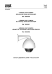
Intelligent Speed Dome Camera
Installation
Manual
Please read this manual carefully before product installation.
Intelligent Dome Camera Installation Manual
P6EV1 07/06/26
Contents
Precautions…………………………………………………………………2
Packing Schematic rawing…………………………………………………4
Video Camera Installation Steps…………………………………………..4
Installation Steps for the Shielding Cover of Dome ………………………5
Bracket Installation Steps………………………………………………….9
Dome Machine Installation Steps………………………………………….9
Schematic Illustration for Connections and Installations…………………12
2
Intelligent Dome Camera Installation Manual
Precaution
1.Before installing and using the camera, please read this manual and The
User Manual of Intelligent Dome Camera.
2.The dome camera uses AC 24V power supply(Indoor 1A/Outdoor 2A).
The rated input voltage is attached at the bottom of the camera or
relevant places.
3 . Interior of the Dome device are precision
optical and electrical instruments. Heavy
pressure, shock and other incorrect
operations should be prevented during
the processes of delivery, storage and
installation. Otherwise, may cause
damage on product.
4.Please do not remove and disassemble any internal parts of Dome video
camera by self in order to avoid normal usage being impacted. There is
no part inside the device, which can be repaired by users themselves.
5 . During usage, user should abide by all electrical safety standards and
adopt the special power provided with
the Dome video camera. During
transmission, RS-485 and video signal
should be retained enough distance
with high-voltage equipments or
cables. When necessary, thunderproof, surge-proof and other protecting measures should be carried out.
6 . Indoor Dome is only for indoor use in order to avoid the Dome video
camera to be rained or be affected with humidity, etc. Please do not use
the product in humid place.
7.Please do not use the product under the situations of exceeding specified
temperature, humidity or power supply specifications.
8.No matter whether power of the Dome video camera is connected or not,
3
Intelligent Dome Camera Installation Manual
please do not aim the video camera at sun or extremely bright object and
do not aim or monitor the video camera at bright static object for long
time.
9 . Please do not use strong or caustic
washing lotion to clean the main
body of the Dome video camera.
After dirt is cleaned up, please use
cotton fabric to clean the product.
10 . Shall use the high-speed Dome
video camera carefully and avoid
being stroked or shocked.
11.When install the Dome Video Camera, please install it in the place with
enough holding force.
12.If camera lens adheres with dust, please use special lens paper to clean
up.
I. Packing Schematic Drawing
4
Intelligent Dome Camera Installation Manual
Fig 1 is the sketch of the upper deck and Fig 2 shows the lower deck.
Manual
s
BNC cables
Acrylics
亚克力罩
clear cover
罩
Fig 1
AC24V Power supply
Supply
Dome machine
Bracket
Shielding cover
Fitting Bag
Fig 2
II. Video Camera Installation Steps
Step 1: Insert one end of the cable for video camera into the corresponding
interface on the base plate of the dome machine (as Fig 4) indicated, and
Fig 3 is the description about wire harness.
5
PWM2*4
Intelligent Dome Camera Installation Manual
Metal Surface
Fig 3
Push in and Compress the
Cable Here
Fig4
Step 2: Install the video camera on the camera fixing base of the dome
machine, as indicated in Fig 5.
Attention!
Please don’t scratch the lens when video camera is being installed. The main6
Intelligent Dome Camera Installation Manual
body machine sizes are different according to different models of video
camera. After installed the camera and before being turned on, please test by
manual to confirm that the camera doesn’t touch the Acrylic cover or other
parts.
Fix.with PWM2*4 Screw
Fig 5
Step 3: Insert the other end of cable into the port of video camera, as
indicated in Fig 6 and Fig 7.
push in here and compress the cables
Fig6
Fig.7
Cable to be Inserted Here
III. Installation Steps for Shielding Cover of Dome
7
Intelligent Dome Camera Installation Manual
Fig 8 shows the fixing holes of the shielding cover, 4 pcs M3 screw holes in
total.
Fixing Hole for the
Shielding Cover
Fig 8
Align Fixing Hole of the Shielding Cover
Fig 9
Fix with PM3*16 Screws
Fig 10
Fig 11
8
Intelligent Dome Camera Installation Manual
Align the Screw Head
Turn in the Clockwise Direction
Fig 12
Fig 13
Step 1: Align the opening of the shielding cover for machine to the lens of
video camera, and align the 4 holes on the shielding cover and the 4
pcs M3 screw holes on the dome machine, as indicated in Fig 8 and
Fig 9.
Step 2: Lock up the 4 PM3*16 slotted set screws, as indicated in Fig 11.
Step 3: Align the acrylics clear cover to the screw joint of the dome
machine, turn in the clockwise direction and tighten it up, as
indicated in Fig 12 and Fig 13.
9
Intelligent Dome Camera Installation Manual
IV. Bracket Installation Steps
Step 1: Pass the connecting wire of dome machine through the hollow
tube of the bracket. Check whether there is any residual inside
the hollow tube of the bracket before passing the wire
through, as indicated in Fig 14.
Fig14
Fig 15
Step
2: Fix the bracket that has
been passed with connecting wire onto the wall with 4 pcs M6
explosion screws, as indicated in Fig 15.
V. Dome Machine Installation Steps
Step 1: Insert the plug of the connecting wire for the dome machine
into the interface on the upper part of dome machine as
indicated in Fig 16 and Fig 17.
Fig.16
Fig.17
10
Intelligent Dome Camera Installation Manual
11
Intelligent Dome Camera Installation Manual
Step
2:
machine
it up with 3-M5*14 screw, as indicated in Fig 18.
Fig 18
Buckle
the
dome
into the bracket, and lock
Attention !
There is a waterproof ring on the M5*14 screw and attention shall be paid to
fix it properly. There is a foam blank waterproof ring in the connecting place
of the upper part of outdoor dome machine and the bracket, and attention
shall be paid that it should be cemented and impacted to prevent rainwater
from entering the dome machine. The material for indoor machine is silicon
gel mat.
Connect to the dome
AC24V Power supply
Input AC220V/110V
12
Intelligent Dome Camera Installation Manual
VII. Schematic Drawing of Installation Connections
13
Intelligent Dome Camera
Operation Manual
(English Version)
Please read this manual carefully before installation and use
(Announcement: This manual will be subject to revision without further notification)
Operation Manual of Intelligent Dome Camera
2
Operation Manual of Intelligent Dome Camera
Content
Precaution………………………………………………………………………………………………….………1
Chapter One Product Overview
I. Performance instruction…………………………………………………………………………………….…3
II. Feature Functions Instruction………………………………………………………………...………………4
Chapter Two Wiring and Setup of Dome System
I. Wiring of Dome System………………………………………………………………………………………5
1. Minimum system connection……………………………………………………………………………5
2. Multi-dome device connection…………………………………………………………………….……5
II. Setting of Dome Device communication …………………………………………………..…………….…6
1. Setting protocol and baud rate of dome device…………………………………………………………7
2. Address setting of dome device…………………………………………………………………………7
Chapter Three Fast Operation Guide of Dome Device
I. Wiring…………………………………………………………………………………………………………8
II. Setting protocol and baud rate……………………………………………………………………….………8
III. Setting dome device address…………………………………………………………………………...……9
IV. Install camera……………………………………………………………………………………….….……9
V. Connect the power of dome device………………………………………………………………….….……9
VI. Controller setting……………………………………………………………………………………………9
VII. Start testing…………………………………………………………………………………………………9
VIII. Complete the test (Summary)………………………………………………………………...……………9
Chapter Four English Operation Menu of Dome Device
I. Main menu……………………………………………………………………………………………………10
II. Tree Menu List………………………………………………………………………………………………10
1. Language Options………………………………………………………………………………………10
2. Display options…………………………………………………………………………………………10
3. Control options…………………………………………………………………………………………12
4. Diagnostic Options…………………………………………………………………………..…………13
5. Camera Options…………………………………………………………………………………...……13
6. Function Programming…………………………………………………………………………………15
Chapter Five Short-cut Operations and Specification of Dome Device
1. Short-cut operation table………………………………………………………………………………18
2. Main Technical Indexes………………………………………………………………..….…..………19
Chapter Six Trouble Shooting of Dome Device
1. Trouble shooting table……………………………………………………………………………..…..20
3
Operation Manual of Intelligent Dome Camera
Chapter One Product Overview
I. Performance instruction:
1. Address of Dome device is from 0 ~ 255. The number (address) of dome device in the control system is setup by the
hardware (8-digit on and off switch) of dome device.
2. Integrate multi-protocol and auto protocol differentiation. Note: The dome device only auto differentiate
controller of the first communication.
3. Pan 360 degree continuous rotation.
4. Tilt 90 degree action plus 2 degree angle adjustment.
Plus the 2 degree adjustment, the view angle can be 90 or 92 degree.
5.Pan manual operation speed can be 0.1 to 300 degree per second
6.Tilt manual operation speed can be 0.1 to 120 degree per second
7. 128 pershot positions.(A fixed position that aimed by the dome camera, which can be set and revised by user arbitrarily)
8. The maximum running speed when preshot is being called can reach 400 degree per second with accuracy
of ±0.1 degree.
9.Compatible with many kinds of Module Camera.(Sony, Hitachi, Sanyo, Yoke, CNB, LG, Haitron,Samsung)
10.Power supply: AC 24V1.5A(indoor type), AC 24V2A(outdoor type)
11.Easy installation interface.
12.Pass environmental protection grade IP66 (outdoor type)
13.Adopts long distance RS-485 transmission mode
14.Transmission speed, i.e. Baud rate is selectable. (Set by the fifth and sixth bit of the on and off switch of the dome
device. 2400bps~19200bps)
II. Feature Functions Instruction:
1. Multi-language operation menu and function display.
2.Camera name and operation position and angle display. (The name of the camera can be edited and the coordinate
angle of the dome device can be displayed on the screen.)
3. Operation crosshair function(Enable this option, the target can be captured more effectively with crosshair on the screen.)
4. Three PTZ tours operation with 2 minutes record of each tours. ( Can real-time monitor and record the action of
manual operation)
4
Operation Manual of Intelligent Dome Camera
5. Six group of programmable vector scans (including scan speed, dwell time, preshot and interruption between tours)
6. Auto flip function with 10 degree move up
7. Eight sectors of programmable sectional mask. (Can mask part of the sectors of camera, which differs depending on
different types of camera)
8. Eight sectors of programmable sectional display. (Can display the name and nature of concrete position shooting by the
camera, which differs depending on different types of camera)
9. Auto enter function running after self-test of the dome device and auto enter function running when there is
no transmission. (Dwell time can be set from 1 to 999 seconds)
10. Frozen video picture function.(freez picture function)
11. Operation return function.(after executing operation return, the dome device will return to the previous operation)
12. Intelligent manual scan function. ( execute this function in manual pan operation, you can adjust the manual pan
operation)
13. Intelligent power off real time memory.(If power was cut off when a certain function is in operation, the dome device can
resume working at where the power is cut off.)
14. High efficient 3-dimension scan.
15. Camera zoom in speed limit function.(When it was zooming in, the speed of the dome device will auto slow down.)
5
Operation Manual of Intelligent Dome Camera
Chapter Two Wiring and Setup of Dome System
I. Wiring of Dome System
1.Basic system connection.(One dome device)
From the basic system connection, user can understand the electric wiring attribute of the dome device and bring
great operation convenience of installation, testing and demo. When using this product for the first time, please
read carefully and follow this electric wiring drawing as any wrong wiring may lead to permanent damage of the
dome device or damage of other equipment.
Socket of dome
device
GND/No need when testing
接大地 / 试机时可不接
GND/No need when testing
Connecting cable
Image displayer
Video+
VideoAC24V (Red)
Power
of
dome device
AC24V (Black)
Control signal+ (orange)
Control signal- (yellow)
Dome device
controller
Power of
keyboard
In the drawing, JMP-120R is the impedance matching selection of control signal and noise restrain of RS-485, when
there is long distance transmission or noise-control, it can short jumper
!Attention: No operation when the dome device is power on.
2. Multi-dome device connection.
When connecting many dome devices together, the user can embed multi-device system with auxiliaries such as
arrester device, video matrix, DVR and alarm box for system integration.
AC24V: Power supply of dome device, which will convert 110V/60HZ or 220V/50HZ input to AC 24V output
and supply to the dome device.
RS-485 Bus: It is for the control signal ( RS-485 signal ) output of controller, connecting to the
communication input terminals of control cable of each dome device.
Video: It is for image signal output of dome device, (can directly output to video equipment such as monitor or
video matrix. Take care of the match up of impedance.)
6
Operation Manual of Intelligent Dome Camera
RS-485
AC24V
Power of
dome
Video
Dome #1
Image
displayer
RS-485
AC24V
Power of
dome
Video
Dome #2
Image
displayer
RS-485 Bus
Dome
device controller
RS-485
AC24V
Power of
dome
Video
Dome #N
Image
displaye
r
(Wiring of multi-dome)
II. Setting of Dome Device communication
PELCO-D
ON
ON
OFF
OFF
**
**
switch
PELCO-P
OFF
OFF
ON
OFF
**
**
Auto
Differentiate
Actiontop
System reserve
OFF
OFF
OFF
OFF
**
**
ON
ON
ON
ON
**
**
波特
率设置
rate setting
Baud
Protocol type
协议
设置
setting
Protocol
拔On/Off
码开关
Before installation and use, the setting of communication protocol and transmission speed (baud rate) should comply
with the control system.
1.Setting protocol and baud rate of dome device.
On/Off
3rd digit 4th digit 5th digit 6th digit
1st digit
2nd
status
digit
7
Operation Manual of Intelligent Dome Camera
Attention: the protocol and baud rate of dome device should comply with those of controller, which need to be restarted
after revision.
On/Off status 5th digit 6th digit
Baud rate
This figure shows protocol of
PELCO-D, Baud rate of 2400.
2400
OFF
OFF
4800
OFF
ON
9600
ON
OFF
19200
ON
ON
2. Address setting of dome device.
On/Off switch
Setting method: The sum of switch numbers when it is at ON
position is the address of dome device.
Matching numbers
On/off switch and
matching numbers
Setting address for dome device (this
figure shows the address of dome
device No 1).
1
2
4
8
Calculation example of dome device address:
2
16
4
(2+4+16=22)the address is 22.
Dome device range: 0~255.
8
128
64
32
16
Operation Manual of Intelligent Dome Camera
Chapter Three Fast Operation Guide of Dome Device
I. Wiring (Please do not turn the power on).
II. Setting protocol and baud rate. (Turn the power off when setting, and restart the device after revision).
Baud rate setting
Protocol setting
Baud rate setting
Protocol setting
The figure shows: Protocol: PELCO-D
The figure shows: Auto detection protocol.
Baud rate: 2400 bps
Baud rate: 2400bps
(Please refer to detailed parameter in next chapter)
(Please refer to detailed parameter in next chapter)
This dip switch located on PCB in the dome device
9
Operation Manual of Intelligent Dome Camera
III. Setting dome device address. (Turn the power off when setting, and restart the device after revision).
The figure shows: Address of the dome device: No. 1
(Please refer to detailed parameter in next chapter)
Set address for dome
This dip switch located on PCB in the dome device
IV. Install camera. (Please refer to camera installation for details).
Attention: 1. Do not connect the camera and dome device with FFC in a wrong way.
2. The installation holes of different camera differ.
V. Connect the power of dome device.
At this moment, the self-test (rotation) of dome device and self-test (there will be image on the monitor) of camera can
be seen.
Attention: When the dome device is self-testing, it is normal when sound is issued caused by the block of dome device
after 2~5 seconds of vertical movement, which is the tilt orientation of the dome itself.
VI. Controller setting.
Set the protocol, baud rate and address of the keyboard controller identical with those of dome device. (Please
refer to keyboard controller instruction manual).
Attention: If the setting of protocol of dome device is auto detection, the protocol of keyboard controller can be set
arbitrarily. But its baud rate should be set identical with that of the dome device.
VII. Start testing.
When all the above are ready, the testing to dome device can be started.
1. Direction control test of dome device
2. Zooming control test of camera
up
Rotate
Left
right
左
Zoom in
down
Zoom
out
The directions (up, down, left and right) of the
Zooming of the camera can be controlled by
dome device can be controlled by using the
zooming function Joystick or by using TELE (zoom in)
keyboard controller, as indicated in the figure.
and WIDE (zoon out) on the keyboard button.
Note: the working of dome device is normal
Note: The camera and dome device are normal
(Please refer to the next section for demonstration of menu operation and control of dome device.)
VIII. Complete the test. (Summary).
1. If the performance of item 7 is normal, it indicates the system is basically normal. Please do not change the wiring
and various setting to avoid fault and unnecessary damage and loss.
2. If the performance of item 7 is abnormal, or only one item works normally, please check the wiring (item 1 and 4)
and setting (item 2, 3 and 6) carefully.
10
Operation Manual of Intelligent Dome Camera
Chapter Four -English Operation Menu of Dome Device
I. Main menu
<1>. Press CALL+90+ENTER on the keyboard to enter the main menu of dome device (fig.1).
<2>. Select options Joy stick only between up and down, the arrow points to the current selected
option. Press OPEN or left or right of Joystick to command entering the submenu of that option or
change the value or setting of that option.
<3>. Press CLOSE to exit menu or return to upper stage menu.
[View1]
- - - - - - - - - FUGA6 - - - - - - - - -
1.Language
English
2.Display options
3.Control Options
4.Diagnostic Options
5.Camera Options
6.Function Programming
<< Language options
<< Display options
<< Control options
<< Diagnostic options
<< Camera options
<< Functions programming
IRIS CLOSE to Exit
II. Tree Menu List.
<1>.All sub-menus can be seen clearly in this tree list.
1.Language
English
2.Display options
<< Language options
Joystick left or right to select
<< Display options
1.Preshot (Preset position) setup << Preshot setup options
1.Numder
1
<< Preshot number selection Press OPEN or Joy stick left or right to enter
1~165
<<The default number after entering is 001. (hundred bit/ten bit/single bit). Joy stick left or right to
001
select preshot position and press OPEN to confirm, and Joy stick left or
0123456789
right again to select numbers (0~~9). Press OPEN to confirm the
IRIS CLOSE When Done
selection.
Press CLOSE to exit or return to upper stage menu when programming
is done. Press OPEN or Joy stick left or right to enter
2.Set Preshot
<< Set preshot
Select preshot and press CLOSE to confirm the
IRIS CLOSE When Done
programming when done and auto exit and return to
11
Operation Manual of Intelligent Dome Camera
3.Call Preshot
Call out
4.Delete preshot
Are you sure to do this?
IRIS OPEN to Confirm
IRIS CLOSE to Cancel
5.Name
the upper stage menu.
<< Call preshot.
The action of the dome device can be seen and
return to corresponding preshot point.
<< Delete preshot.
<<Reminder: Are you sure to delete preshot?
Press OPEN to confirm
Press CLOSE to exit and return to upper stage menu.
_ _ _ _ _ _ _ _ <<Edit the name of preshot. Press OPEN or Joy stick left or right to enter
________
0 12 34 56 78 9ABCDE FGH IJKLMN
OPQRSTUVWXYZ_
IRIS CLOSE When Done
6.Name Display
ON/OFF
<<Joystick left or right when programming to select
preshot and press OPEN to confirm.
Joystick left or right to select (0~~9 or A~~Z).
Press OPEN to confirm selection.
Press CLOSE to exit or return to upper stage
menu when programming is done.
<<Name display On/Off
Joystick left or right to select
IRIS CLOSE to Exit
2.Sector Setup
1.Number
2.Name
<<Sector setup
Press OPEN or Joy stick left or right to enter
(1~8)
<<Number selection
_ _ _ _ _ _ _ _ <<Name editing
PressJoy
OPEN
or left
Joy stick
left or
to enter
stick
or right
toright
select
<< Joy stick left or right when programming to select
preshot and press OPEN to confirm.
Joy stick left or right to select (0~9 or A~Z). Press
0 1 2 3 4 5 6 7 8 9 A B C D E F G H I J K L M N OPEN to confirm selection.
Press CLOSE to exit or return to upper stage menu
OPQRSTUVWXYZ_
when programming is done.
IRIS CLOSE When Done
________
3.Pan Start pos
0.0
<<Setup pan start point. Press OPEN or Joy stick left or right to enter
Capture the start point and press CLOSE to exit and return to upper stage menu.
IRIS CLOSE When Done
4.Pan End pos
0.0
<< Setup pan end point. Press OPEN or Joy stick left or right to enter
Capture the end point and press CLOSE to exit and return to upper stage menu.
IRIS CLOSE When Done
5.Tilt Start pos
0.0
<< Setup tilt start point. Press OPEN or Joy stick left or right to enter
Capture the start point and press CLOSE to exit and return to upper stage menu.
IRIS CLOSE When Done
6.Tilt End pos
0.0
<< Setup tilt end point. Press OPEN or Joy stick left or right to enter
Capture the end point and press CLOSE to exit and return to upper stage menu.
IRIS CLOSE When Done
7.Name display
ON/OFF << Sector name display On/Off Joy stick left or right to select
12
Operation Manual of Intelligent Dome Camera
IRIS CLOSE to Exit
3.Coordinates ON/OFF << Coordinates display On/Off Joy stick left or right to select
4.Crosshairs ON/OFF << Crosshairs On/Off Joy stick left or right to select
5.Start-UP Scr Msg ON/OFF << Start-up screen message display On/Off
Joy stick left or right to select
IRIS CLOSE to Exit
3.Control options << Control options Press OPEN or Joy stick left or right to enter
1.Set pan and Tilt << Pan/Tilt setup of dome device
Press OPEN or Joy stick left or right to enter
1.Pan Reverse
ON/OFF << Pan Reverse
ON/OFF Joy stick left or right to select
2.Tilt Reverse
ON/OFF << Tilt Reverse
ON/OFF Joy stick left or right to select
3. +2 Tilt Limit
ON/OFF <<+2 Tilt Limit
ON/OFF Joy stick left or right to select
4.Find Home on STA ON/OFF << Find Home on start ON/OFF Joy stick left or right to select
IRIS CLOSE to Exit
2.Set Default Function << Set default function Press OPEN or Joy stick left or right to enter
1.Default Function P/V/T<<Select default function (Preshot/Tour/PTZ) Press OPEN or Joy stick left or right to enter
2.Number
1 << Function number selection Press OPEN or Joy stick left or right to enter
<< Joy stick left or right when programming to select preshot and press
OPEN to confirm.
Joy stick left or right to select (0~~9). Press OPEN to confirm
selection.
Press CLOSE to exit or return to upper stage menu when
programming is done.
1~165
001
0123456789
IRIS CLOSE When Done
3.Delay
001
<<Time delay setting (second) Press OPEN or Joy stick left or right to enter
1~999
001
0123456789
IRIS CLOSE When Done
<< Joy stick left or right when programming to select preshot and
press OPEN to confirm.
Joy stick left or right to select (0~~9). Press OPEN to confirm
selection.
Press CLOSE to exit or return to upper stage menu when
programming is done.
4.Operation
ON/OFF << Default function On/Off Joy stick left or right to select
IRIS CLOSE Exit
ON/OFF << Operation speed limit On/Off Joy stick left or right to select
3.Speed Limit
ON/OFF << Auto flip On/Off Joy stick left or right to select
4.Auto Flip
PTZ/OFF/Z << Auto focus options Joy stick left or right to select
5.Auto Focus
PTZ/OFF/Z << Auto AE option Joy stick left or right to select
6.Auto AE
7.Vector scan AF ON/OFF << Vector scan auto focus control Joy stick left or right to select
IRIS CLOSE to Exit
4.Diagnostic Options << Diagnostic options
1.Clear Memory
Press OPEN or Joy stick left or right to enter
<< Clear data in the memory Press OPEN or Joy stick left or right to enter
Are you sure to do this?
IRIS OPEN to Confirm
IRIS CLOSE to Cancel
<< Reminder: are you sure to do this.
Press OPEN to confirm.
Press CLOSE to exit and return to upper stage menu.
13
Operation Manual of Intelligent Dome Camera
2.Restore Def Setting
<< Restore default setting Press OPEN or Joy stick left or right to enter
<< Reminder: are you sure to do this.
Are you sure to do this?
Press OPEN to confirm.
IRIS OPEN to Confirm
Press CLOSE to exit and return to upper stage menu.
PAL/NTSC << PAL/NTSC switch Joy stick left or right to select
IRISsystem
CLOSE to Cancel
3.Color
4.Scan & Camera Reset(Null) << Restart dome camera.Press OPEN or Joy stick left or right to enter
5.Dome Information << Dome information. Press OPEN or Joy stick left or right to enter
---------------FUGA6-------------Camera:x x x x x x x x
Protocol:x x x x x x x x
Baud rate: x x x x
Dome No.:x x x
Version:x x x x
IRIS CLOSE to Exit
<< Name of dome
<< Type of camera
<< Control protocol
<< Baud rate
<< Dome number
<< Press CLOSE to exit and return to upper stage menu.
5. Camera Options (Take Sony camera as example) << Press OPEN or joystick left/right to enter
1.Zoom and Focus
<< Press OPEN or joystick left/right to enter
⒈.Zoom Speed
7
⒉.Digital Zoom
ON/OFF
⒊.AF Sensitivity High/Low
IRIS CLOSE to Exit
2.Camera Exposure
<<
Joystick left/right to select
<< Joystick left/right to select
<< Joystick left/right to select
<< Press OPEN or joystick left/right to enter
⒈AE Mode Auto/Manual/shutter/Iris/Bright
⒉.Slow Shutter
⒊.shutter Speed
<< Joystick left/right to select
<< Joystick left/right to select
OFF/ON
<< Joystick left/right to select
Auto/Manual
(Note: It is adjustable only when the AE is under manual operation or shutter mode)
⒋.Iris level
<< Joystick left/right to select
Auto/Manual
(Note: It is adjustable only when the AE is under manual operation or IRIS mode)
⒌.AGC Level
<< Joystick left/right to select
Auto/Gain
(Note: AGC Level is adjustable only when AE is under manual operation)
⒍.Bright Level
<< Joystick left/right to select
Auto/Manual
(Note: It is adjustable only when the AE is under Bright Level)
⒎.Spot AE
OFF/ON
⒏.WDR
OFF/ON (Need camera support)
<< Joystick left/right to select
<< Joystick left/right to select
IRIS CLOSE to Exit
3.Mask Zone
<< Press OPEN or joystick left/right to enter
⒈.Numder ( 1~24 )
⒉.Mask Edit
<<
No. 1~24
Joystick left/right to enter
<< Press OPEN or joystick left/right to enter
<<
IRIS OPEN to Begin
IRIS CLOSE When Done
⒊.Mask Display OFF/ON
IRIS CLOSE to Exit
Select the mask zoon to be masked, press OPEN and press NEAR (Tilt
zoom out) FAR (Tilt zoom in), WIDE (Pan zoom out), TELE (Pan zoom
in).Press CLOSE and return to upper menu.
<< Joystick left/right to select
4.Mask Color << Press OPEN or joystick left/right to enter
⒈.Mask Color Gray5 << Masking color option(gray1\gray2\gray3\gray4\gray5\gray6\white\ red\green\blue\
blueness\yellow\magenta\black)Joystick left\right to select
14
Operation Manual of Intelligent Dome Camera
⒉.Semi-transparency OFF\ON
IRIS CLOSE to Exit
5.Others
<< Joystick left\right to select
<< Joystick left\right to enter
⒈.Sharpness
⒉.Black Light
⒊.WB Mode
⒋.R Gain
<< 0~15 Joystick left\right to enter
5
<< Joystick left\right to enter
OFF\ON
Auto\Manual\Indoor\Outdoor\Onepush\ATW
<< Joystick left\right to enter
<< Joystick left\right to enter
Auto
(Note: R Gain is effective when White Balance is under manual operation)
⒌.B Gain
<< Joystick left\right to enter
Auto\manual
(Note: B Gain is effective when White Balance is under manual operation)
⒍.Vertical Mirror
<< Joystick left\right to enter
OFF\ON
⒎.Horizontal Mirror
OFF\ON
<< Joystick left\right to enter
⒏.IR SW Mode Auto\Color\ B\W
⒐.Stabilization
<< Joystick left\right to enter
<< Joystick left\right to enter
OFF\ON (Need camera support)
⒑.Function OSD
ON\OFF
<< Joystick left\right to enter
IRIS CLOSE to Exit
⒒Line Sync
OFF\ON
IRIS CLOSE to Exit
<< Joystick left\right to enter
6.Function Programming << Special function programming Press OPEN or Joystick left or right to enter
1. PTZ Tour(Pattern)
1.Number
( 1 ~3 )
2.Name
________
<<
Pan/Tilt/Zoom tour programming Press OPEN or Joystick left or right to enter
<<PTZ
tour number Joystick left or right to select
<<Edit PTZ name Press OPEN or Joy stick left or right to enter
<<
________
0 12345678 9ABCDEFGHIJKLMN
OPQRSTUVWXYZ_
IRIS CLOSE When Done
3.Program a Tour
<<Enter PTZ tour programming Press OPEN or Joy stick left or right to enter
IRIS OPEN to Begin
IRIS CLOSE to Exit
4.Run a Tour
Joystick left or right when programming to select
preshot and press OPEN to confirm.
Joystick left or right to select (0~~9 or A~~Z).
Press OPEN to confirm selection.
Press CLOSE to exit or return to upper stage
menu when programming is done.
<<Press OPEN to confirm and start programming.
<<Press CLOSE to exit the programming and return to upper stage menu.
<<Run Pan/Tilt/Zoom tour (pattern) Press OPEN or Joy stick left or right to enter
Call out
5.Delete a Tour
<<Delete PTZ tour. Press OPEN or Joy stick left or right to enter
Are you sure to do this?
IRIS OPEN to Confirm
IRIS CLOSE to Cancel
<< Reminder: are you sure to do this.Press OPEN to confirm.
Press CLOSE to exit and return to upper stage menu.
6. Name Display
ON/OFF <<PTZ tour name display On/Off Joy stick left or right to select
IRIS CLOSE to Exit
15
Operation Manual of Intelligent Dome Camera
2.Program Vector Scan
1.Number
( 1 ~~ 6 )
2.Program a Vector scan
1
2
3
<< Program vector scan. Press OPEN or Joy stick left or right to enter
<<Vector scan number Joy stick left or right to select
<<Vector scan programming Press OPEN or Joy stick left or right to enter
Name Num V Dwell
_
_ _ _
_
_ _ _
_
_ _ _
<<Joystick arbitrarily to move the
cursor, and stop the cursor at place of
programming. Press OPEN to enter
the selection.
16
IRIS CLOSE When Done
Function name
Name
Function number
Num
<< Press OPEN continuously to select P: Preshot,
P/T/V
T: self-study (pattern or PTZ tour), V: vector scan
1~293
001
0123456789
IRIS CLOSE When Done
Velocity selection
V
Dwell time
Dwell
<< Press OPEN continuously to select
1~9
1~99
001
0123456789
IRIS CLOSE When Done
3.Run a Vector Scan
<< Joy stick left or right when programming to select
preshot and press OPEN to confirm.
Joy stick left or right to select (0~9). Press OPEN
to confirm selection.
Press CLOSE to exit or return to upper stage
menu when programming is done. stage menu
when programming is done.
<< Joy stick left or right when programming to select
preshot and press OPEN to confirm.
Joy stick left or right to select (0~9). Press OPEN
to confirm selection.
Press CLOSE to exit or return to upper stage
menu when programming is done.
<< Run vector scan. Press OPEN or Joy stick left or right to enter
Call out
4.Delete a Vector Scan << Delete vector scan Press OPEN or Joy stick left or right to enter
Are you sure to do this?
IRIS OPEN to Confirm
IRIS CLOSE to Cancel
<< Reminder: are you sure to do this.
Press OPEN to confirm.
Press CLOSE to exit and return to upper stage
menu.
IRIS CLOSE to Exit
3.Program Alarms
1
2
3
4
<< Program alarms. Press OPEN or Joystick left or right to enter
Name
P/V/T
Name Num E/N
<< This function is not available
Num at the moment.
_
_
_
1~128
_
_
_
0
_
_
_
_
_
_
0123456789
IRIS CLOSE to Exit
IRIS CLOSE When Done
E/N
16
N/Y
Operation Manual of Intelligent Dome Camera
IRIS CLOSE to Exit
17
Operation Manual of Intelligent Dome Camera
Chapter Five Short-cut Operations and Specification of Dome Device
1.Short-cut operation table
System Preset Short-cut Operation Table
PreShot 80 (Call 80)
Run PTZ Tour 1
PreShot 81 (Call 81)
Run PTZ Tour 2
PreShot 82 (Call 82)
Run PTZ Tour 3
PreShot 83 (Call 83)
Start VectorScan 1
PreShot 84 (Call 84)
Start VectorScan 2
PreShot 85 (Call 85)
Start VectorScan 3
PreShot 86 (Call 86)
Start VectorScan 4
PreShot 87 (Call 87)
Start VectorScan 5
PreShot 88 (Call 88)
Start VectorScan 6
PreShot 89 (Call 89)
Joy sticks between freeze and unfreeze video
PreShot 90 (Call 90)
Setup the Menus and Camera
PreShot 91 (Call 91)
Invokes the Flashback Function
PreShot 92 93 94
Reserve
Description of the preset point:
Preset point of the position: 1-50, 64-77,102-165 (totally 128)
Function short-cut preset point: 51-63, 78-101
Note: Dome operation will be different due to controller’s different specs.
Preset point setting:
Method 1: Press “PRESET” + “No.” + “ENTER” by using AT525 Controller.
Method 2: Press “No.” + “Shot.” + “ON” by using AT505 Controller.
Call Preset point:
Method 1: Press “Call” + “No.” + “ENTER” by using AT525 Controller.
Method 2: Press “No.” + “Shot.” + “ACK” by using AT505 Controller.
Clear Preset point:
Method 1: Press “PRESET ” + “No.” + “OFF” by using AT525 Controller.
Method 2: Press “No.” + “Shot.” + “OFF” by using AT505 Controller.
2. Description of “cruise track” function:
a) When enter “PRESET+51+Enter”, the device is enabled system default cruise track. The device will auto scan
point by point from No.1 preset position to No.16 preset position. If certain position has not been preset or been
cleared after preset, “cruise track” will not scan them.
b) Dwell time of the preset position is 2 seconds.
18
Operation Manual of Intelligent Dome Camera
c) About other 6 cruise tracks operation, please refer operation manual of the keyboard controller. Different
controller is with different operation.
3. Description of “Line-Scanning” function:
a) Dome device will auto line-scan between two specified points.
b) User can set the start point by “PRESET+52+Enter” and end point by “PRESET+53+Enter”.
c) Line scanning speed set: user keep a manual line scan speed three seconds above, then
through“CALL+51+Enter” to save the speed as line scan speed, use“CALL+52+Enter” to enable the line scan.
d) Dwell time of line-scanning between “starting point” and “ending point” is 2 seconds.
4. Intelligent manually pan continuous scan:
When user use joystick for pan scan monitoring, keep manually 3 seconds, then press “CALL+101+Enter”, the dome
can go on with the scan speed and monitor position automatically .
5.Main Technical Indexes
Specification
Power
AC24V 2.0A
Power
Consumption
Weight
18VA (without camera)
Installation
Method
Relative
Humidity
Operating
Temperature
3Kg (without camera)
Hanging-type ceiling-style, bend-tube type, etc (optional)
10-75%(under the condition of without condensation)
-2 0℃~5 0℃(normal range)
19
Operation Manual of Intelligent Dome Camera
Chapter Six Trouble Shooting of Dome Device
Problem
Description
After power on, no
motion and no
image.
Possible Reason
Troubleshooting
Remarks
Power cable is connected
improperly.
Fault of power PCB of dome
device
slip
ring
power
wires
disconnected
Fault of main control board
Check if the power cable is connected
to power of AC24V
Change the power PCB
Please follow the above
basic
system
wiring
strictly
After power on,
the dome device
rotate
normally,
but no character
nor image display
Character monitor switch is off
Switch on the character monitor
according to the menu instruction
Improper connection between
camera and dome device
Replace a FFC cable or a camera
After self-test of
the
dome
device,
menu
cannot
be
displayed
Distorted character
or image
wrong operation
CALL+90+ENTER open
Fault of OSD control board
Change OSD board
Interfered by exterior electronic
signal (noise) or the camera
is directed to the monitor
screen
System wrong function
Grounding the dome device or shut off
the surrounding big
electronic
devices(electric, HF, signal generating)
equipment, or rotate the camera
Restart the dome device
Shielded cable should be
adopted for video cable
5
After power on, no
self-test and motor
is locked
Connect the controller and set correct
transmission protocol and baud rate as
well as dome device address
There is character display
in normal circumstance
6
Cannot stop pan
rotation (rotate and
The system setting is start selftest after receiving command
and you can see the video on
the screen
OSD board is not properly
connected with main control
board or the photoelectric
switch is broken
Pan interupter is not in due
position
The system is checking the data
again
fix OSD board again, if the problem
still exits, then replace the OSD
board
Pan interupter should be at
2/3 of the central slot
within
photoelectric
switch
S.N.
1
2
3
4
stop alternatively)
7
After
normal
working, it will
rotate one circle
when
being
controlled
Change slip ring
Change main control board
About 45 second after the
dome device is power
on.
After self-test, the menu
can only be displayed
when there is image
display of the dome device
Adjust the pan interupter
It is normal event
If this happens frequently,
please adjust the pan
interupter or check if the
connection is too tight.
8
Vertical range is not
within 90±2 degree with
large deviation
Fault occurs when the dome
device is in tilt movement. It
may be caused by obstacle of
camera of other object,
which lead to early
tilt
movement
Check and adjust the mechanical
installation
9
Self-test is normal, but
cannot control
Wrong setting
Set the protocol, baud rate and
address of dome device
Check the circuit
10
Insensitive control of
dome device
11
Call out function fails
12
Auto action of dome
device periodically
13
One dome working well
while the other does
not under identical
operaion
Improper connection of
control cable
Overload or too long
distance transmission
Improper contact of control
cable
slip ring is demage
RS-485 protective discharge
arresters broken
System failure caused by
noise interference
Add driver
Check the circuit
Replace slip ring
Change 485 protective discharge
arresters
Restart the dome device
No transmission auto “call Called this setting
back” function is set to the
dome device
Something wrong with the check the setting and wiring again
setting or wiring
20
Mostly happen in the
connection
Operation Manual of Intelligent Dome Camera
21