1
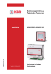
Operating instructions
Function description
multisio
1D2-4CI
Current measuring
module
KBR GmbH
Am Kiefernschlag 7
D-91126 Schwabach
T +49 (0) 9122 6373-0
F +49 (0) 9122 6373-83
E info@kbr,de
www.kbr.de
Operating instructions module multisio 1D2-4CI
Table of Contents
Function description current measuring module multisio 1D2-4CI .. 2
2
Current measuring module - connection chart ................................. 2
3
Current measurement module LED display ........................................ 3
4
Function of scan button ........................................................................ 3
5
Technical data ........................................................................................ 4
EDEBDA0158 / 1010-1 GB
1
Version 1.00
Page 1 of 4
Operating instructions module multisio 1D2-4CI
1
Function description current measuring module multisio 1D2-4CI
The hardware of the multisio 1D2-4CI is equipped with 4 analogous current measuring inputs. Currents of up
to 6A can be measured. The device LED displays different device states by flashing or continuous illumination.
The multisio 1D2-4CI digitizes the 4 currents and calculates the frequency, RMS value and
harmonics up to the 19th harmonic independently. Since the voltage is not measured,
power values cannot be determined. Scanning can be performed at a set frequency
or variably (30 to 70Hz).
The module can be accessed by a master device (multisio xD6 (from 5D6-ESBS-5DI6RO1DO) with module
bus, multicomp with module bus or via computer with VE via Multigate ES/BS) using the module bus interface.
The master device has to configure the module and read out the data acquired by the module for further processing.
The operating voltage is supplied via the module bus interface. The module cannot be used as a stand-alone
unit.
a
Caution!
The multisio 1D2-4CI may only be used with series-connected
current transformers!
The transformers may not be grounded secondarily.
Up to the 690V network (phase to phase voltage), the connected
current transformers have to be designed for a test voltage of at
least 2500VAC for 1 minute.
2
Current measuring module - connection chart
Terminal assignment
Upper terminal row:
Terminal 20: Current input k1
Terminal 21: Current input l1
Terminal 22: Current input k2
Terminal 23: Current input l2
Lower terminal row:
Terminal 24: Current input k3
Terminal 25: Current input l3
Terminal 26: Current input k4
Terminal 27: Current input l4
IN / OUT:
Module bus / supply voltage
EDEBDA0158 / 1010-1 GB
Page 2 of 4
Version 1.00
Operating instructions module multisio 1D2-4CI
a
Note
Connect the current transformers according to the terminal
numbers, i.e. transformer 1 to terminal 20/21, transformer 2 to
terminal 22/23 etc.!
The current inputs of the module are not galvanically separated!
3
Current measurement module LED display
In KBR eBUS scanning mode, the power LED is flashing quickly, in the module detection mode.
In normal operation, the LED is illuminated constantly.
Power LED:
4
Operating voltage
Function of scan button
If the scan button is pressed briefly (until all
LEDs light up for a short time), the module
enters the scanning mode.
EDEBDA0158 / 1010-1 GB
b
Note
Version 1.00
Page 3 of 4
Operating instructions module multisio 1D2-4CI
5
Technical data
Power supply:
Via module bus
24VDC / ca. 1.3W
Connection
Modular connector RJ12:6P6C
Hardware inputs:
4 current measuring inputs Measuring range
Measurement
current input:
0 to 6A AC
Plug terminal 2x 4-pole
Permissible width of
connection lines 2.5 mm2
Fuse protection
NONE!!!
Always short out the current
transformer terminals k and l
before opening the circuit!
Module bus interface:
Serial port
RS485
Module bus connection
RJ12 for ready-made KBR system
cable, max. length 30 m when placed
accordingly
Transfer rate
38400 Bps
Bus protocol
KBR module bus
Display:
LED
1x Operation display / status display
Control unit
Button
Scan button (module bus)
Housing dimensions
90 x 36 x 61 mm (H x W x D)
Mounting type
Wall mounting on DIN rail,
7.5 mm deep, in accordance
with DIN EN 50022.
Weight
approx. 100g
Standards
DIN EN 60721-3-3/A2: 1997-07;
3K5+3Z11; (IEC721-3-3; 3K5+3Z11)
Operating temperature
-5°C ... +55?;
Humidity
5% ... 95%, non-condensing
Storage temperature
-25°C ... +70°C;
Standards
DIN EN 61010-1/A2: 2001 + B1:
2002-11 + B2: 2004-1;
(IEC1010-1/A2)
Protection type
IP20 in accordance with DIN EN
40050 part 9:1993-05
Electromagnetic
compatibility
DIN EN 61000-6-3: 2001 + A11:
2004; (IEC61000-6-3)
DIN EN 61000-6-2: 2001
(IEC61000-6-2)
Mechanical data:
Top hat rail device
Standards and
miscellaneous:
Environmental conditions
Electrical safety
EDEBDA0158 / 1010-1 GB
Page 4 of 4
Version 1.00
An
KBR GmbH
Abteilung Entwicklung
Am Kiefernschlag 7
D-91126 Schwabach
To
KBR GmbH
Development
Am Kiefernschlag 7
D-91126 Schwabach / Germany
Vorschläge:
Korrekturen:
Betrifft Gerät:
Suggestions:
Corrections:
Device concerned
Sollten Sie beim Lesen dieser Bedienungsanleitung oder
Druckschrift auf Druckfehler gestoßen sein, bitten wir
Sie, uns diese mitzuteilen. Ebenso freuen wir uns natürlich über Anregungen, Hinweise oder Verbesserungsvorschläge.
If you come across misprints in this user manual or printed material, please take the time to notify us. We will
also be glad to hear your ideas, notes and suggestions for
improvement.
Bitte geben Sie die betreffende Anleitung oder Druckschrift mit Versionsnummer und/oder Ausgabestand an.
Please identify the user manual or printed material in
question with version number and/or revision number.
Absender / Sender:
Name:
Firma/Dienststelle, / Copany/Department:
Anschrift / Address:
Telefon / Phone:
Telefax / Fax:
email:
Korrekturvorschläge zur Bedienungsanleitung / Druckschrift
Corrections/Suggestions for user manual / Printed material
1309-1 DE / GB
Version