1
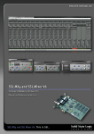
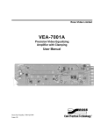
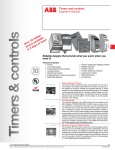
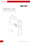
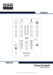
DIGITAL AUDIO WORKSTATIONS
SS8IO-3
8 Channel Audio Interface
User’s Manual
Revision 1.0
Soundscape SS8IO-3 8 Channel Audio Interface
Information in this document is subject to change without notice and does not represent a commitment on the
part of Soundscape Digital Technology Ltd. No part of this document may be reproduced or transmitted in any
form or by any means, electronic or mechanical, including photocopying and recording, for any purpose without
the express permission of Soundscape Digital Technology Ltd or Sydec NV.
The Soundscape SSHDR1-Plus Digital Audio Workstation and the Soundscape SS8IO-3 8 Channel Audio
Interface, when used in conjunction with a PC or compatible computer, form a high quality digital audio recording
device. The unit is intended for recording, editing and arranging of original or authorised material. Users should
note that the use or copying of unauthorised material is illegal and infringes the copyright of the legal owner of
the material. Any person found making illegal copies will be liable to prosecution under copyright law.
Copyright © 1993 to 1998 by Soundscape Digital Technology Ltd. All rights reserved.
Hardware and Software Copyright © 1993 to 1998 by Sydec NV. All rights reserved.
Soundscape and mixtreme are registered trademarks of Soundscape Digital Technology Ltd.
Windows 95, Windows 98 and Windows NT are registered trademarks of Microsoft Corporation.
IBM and PC/AT are registered trademarks of International Business Machines Corporation.
Tascam DA-88 and the TDIF interface are registered trademarks of TEAC Corporation.
Any other trademarks not mentioned above are the property of their respective owners.
The Tascam Digital Interface (TDIF-1) has been licensed by TEAC Corporation and is their sole property.
2
Revision 1.0a
Soundscape SS8IO-3 8 Channel Audio Interface
SS8IO-3 8 Channel Audio Interface
The Soundscape SS8IO-3 8 Channel Audio Interface provides eight high quality analogue input/output
channels, combined with the TDIF (Tascam Digital Interface) multi-channel digital audio interface and 8 channel
LED input level indication. The TDIF digital interface is now an ‘industry standard’ and was originally designed
for the popular digital multi-track tape machine - the Tascam DA-88. This interface now appears on a variety of
different digital mixing consoles, sound cards and converter units.
The SS8IO-3 can be used with the Soundscape mixtreme Soundscape SSHDR1-Plus Digital Audio
Workstation (or with an SSHDR1 upgraded with the SSAC-1 Accelerator Card and Version 2.0 software) to
convert the TDIF interface of the SSAC-1 into eight analogue inputs and outputs.
The unit can also be used to add additional analogue channels to some of the digital mixing consoles that have
TDIF interfaces as standard. Examples of these include the popular Yamaha 02-R and 03-D consoles.
The components used in the SS8IO-3 for analogue input and output are of the highest quality, ensuring that in
this very important area, the audio performance is excellent. The 20 bit analogue to digital (AD) and digital to
analogue (DA) converters are from AKM and are well known as providing superior quality digital audio
conversion. These and the input/output amplifiers are expensive components which meet the exacting
requirements for professional audio recording/reproduction and provide a higher performance level than can be
obtained with converters intended for multi-media applications (as used for low cost soundcards).
The SS8IO-3 also allows sample rate synchronisation using external Wordclock signals or these can be derived
from the TDIF digital interface. Synchronisation with external Superclock signals at 256 x Wordclock rates is also
provided. Superclock is the clocking rate for digital audio devices such as AD/DA converters or digital audio
receivers/transmitters. It can provide a more secure synchronisation method than using Wordclock when several
digital audio devices are connected together and are slaving via timecode to a device such as a video or audio
tape machine, film projector or film editing table. In most circumstances Superclock will not be required.
Front Panel
From the front panel, you can select and view the current sample rate and select the clock source. All current
settings are saved in an internal EEPROM (electrically erasable programmable read only memory) The LED input
metering indicates green there is a signal at a level above -30dBFS and red when the level is above -3dB.
Rear Panel
3
Revision 1.0a
Soundscape SS8IO-3 8 Channel Audio Interface
The SS8IO-3 rear panel has 8 unbalanced analogue inputs and outputs, all with RCA/cinch connectors. A
standard female 25-way sub-D connector for the TDIF port is also provided, with two RCA (cinch) connectors for
generating or receiving external Wordclock or Superclock. An 8-way DIL switch is used to set options for the
Wordclock or Superclock synchronisation.
The unit can be powered with the 9V 230V AC supply (or 115V AC nominal) supplied with the unit, at 50Hz or
60Hz.
Power consumption is 5W.
Technical Specifications
Sample Rates
44.1kHz (-27%) to 48kHz (+12%) with clocks resolved from TDIF or external Wordclock inputs.
Internal sample rate generator 44.1kHz or 48kHz (+/-30ppm)
16kHz to 48kHz (+12%) with Superclock input.
Digital Ports
TDIF (Tascam Digital Interface)
8 Channel bi-directional 24 bit digital interface with 25-way sub-D female connector.
Conforms to Tascam TDIF-1 specification.
Analogue Ports
8 x Analogue Outputs
Single-ended input amplifiers with RCA/cinch connectors.
Output level +3.5dBU.
AKM 20 bit DA Converters.
Maximum output level
Output S/N Ratio
Output THD+N
Output Crosstalk
Frequency Response
Passband Ripple
-
+3dBU
-97dB unweighted
less than –94dB (at 1kHz -20dBFS)
-100dB (at 1kHz FS)
30Hz to 20kHz (-0.2dB)
+/-0.005dB
8 x Analogue Inputs
Single-ended input amplifiers with RCA/cinch connectors.
Input Level +3.5dBU.
AKM 20 bit AD Converters
Maximum input level
Input S/N Ratio
Input THD+N
Input Crosstalk
Frequency Response
Passband Ripple
Input Impedance
-
+3dBU (for full scale)
-97.5dB A weighted
better than 0.01% (at 1kHz -1dBFS)
-100dB (at 1kHz FS)
30Hz to 20kHz (-0.2dB)
+/-0.005dB
30kohms
Metering
8 channel LED input level metering at -30dBFS and -3dBFS.
Clocks
2 x RCA(cinch) connectors for W/S Clock in/out.
Resolves clock from TDIF digital inputs or from external Wordclock or Superclock (256 x Wordclock).
4
Revision 1.0a
Soundscape SS8IO-3 8 Channel Audio Interface
Internal clock generator (44.1kHz/48kHz).
Generates external Wordclock or Superclock signals from any clock source.
Wordclock phase shift is selectable via rear panel Option DIL switches.
Main Operation
The front panel buttons and LED indicators are used to set up the sample
rate and clocks. A description of the operation follows:-
S. RATE
The S. RATE (Sample Rate) button allows the internal wordclock of the
SS8IO-3 to be set to 44kHz or 48kHz. When internal clock is not being
used, the LEDs will indicate the actual sample rate that is being received.
If there is an error or the sample rate does not fall within the tolerances
which are normally expected, then the LEDs will flash. If pressing the S.
RATE button has no effect on the sample rate, then check that the
CLOCK (see below) is set to INT (internal).
CLOCK
The CLOCK button is used to select the source for the wordclock used. A wordclock can be derived from the
TDIF input, or from the external (EXT) wordclock/superclock (W/S CLOCK) input on the rear of the unit, or the
internal (INT) clock can be used. If there is no signal detected for the selected clock source, then the LED will
flash to indicate an error.
Using the SS8IO-3 with the mixtreme PCI Card or SSHDR1-Plus
Generally when the SS8IO-3 is used with an SSHDR1-Plus system, the major requirement will be to turn the 8
digital in/out channels from the SSAC-1 TDIF port into analogue channels. Connect the SS8IO-3 TDIF port to the
TDIF connector on the mixtreme PCI Card or SSHDR1-Plus unit. Normally the TDIF Clock setting should be
used for the SS8IO-3, as the SSHDR1-Plus or mixtreme PCI Card would be set to Internal Clock and so would
determine the sample rate.
Rear Panel Settings
OPTION 8-Way DIL Switch
The OPTION 8-way DIL switch on the rear panel of the SS8IO-3 allows setting of parameters relating to
generating or receiving wordclock (sample rate) and superclock (256 x sample rate) signals for the W/S Clock
in/out and for the TDIF port. These should only be changed from the factory default positions (shown below)
when you have a specific case that requires a different form of clock synchronisation. This would be the case if
you need to use superclock instead of wordclock.
Sync In sets the type of signal required at the W/S Clock input.
Sync Out sets the type of signal generated at the W/S Clock output.
n.c. is a spare switch with the current firmware revision.
Phase Select allows the phase relationship of the wordclock relative to left/right clock (part of the digital audio
stream) to be selected. Some devices specify that there should be for exa mple, a 90° phase shift between the
timing of the wordclock logic signal and the left/right clock, so it can be important in ensuring that the audio data
is transferred error free.
5
Revision 1.0a
Soundscape SS8IO-3 8 Channel Audio Interface
TDIF Out selects the type of wordclock that is generated for the TDIF interface port.
6
Revision 1.0a
Soundscape SS8IO-3 8 Channel Audio Interface
The settings are shown from left to right, so for example, Switch 2 (SyncOut1) is set to ‘0’ (up) and Switch 3
(SyncOut0) is set to ‘1’ (down), so reading both switches gives 01.
1
OPTION
8
Note
= 0
= 1
b7
b6
b5
b4
b3
b2
b1
b0
Factory default settings are as shown in the diagram :TdifOut0
TdifOut1
Phsel0
Phsel1
(not used)
SyncOut0
SyncOut1
SyncIn
Sync In (Sw1)
Sync Out (Sw2, Sw3)
n.c.
(Sw4)
Phase Select (Sw5, Sw6)
TDIF Out (Sw7, Sw8)
Sync In
Sync Out
n.c.
Phase Select
TDIF Out
0 - wordclock
01 - wordclock
101 - 90°
01 - wordclock
0 - wordclock
1 - superclock.
00 - no signal
01 - wordclock
10 - phase shifted wordclock
11 - superclock
100 - 0°
01 - 90°
10 - 180°
11 - 270°
00 - no signal
01 - wordclock
10 - phase shifted wordclock
For the Option DIL switch setting displayed in test mode (see later), the bit positions are as follows :SW1-b7, SW2-b0, SW3-b6, SW4-b1, SW5-b5, SW6-b2, SW7-b4, SW8-b3
Test Mode
There is an internal diagnostic mode which tests the EEPROM, shows the Option DIL switch settings, shows the
firmware revision and checks all LEDS. The test mode can be entered by pressing and holding the S.RATE and
CLOCK buttons for at least 2 seconds during power up. Press any button to advance through 4 diagnostic steps.
Step 1: Release the S.RATE and CLOCK buttons when following LED's illuminate (hold down longer than 2
seconds):
TDIF, ch#2(red),ch#4,ch#6,ch#8
The Unit is now in "non-volatile
memory" test mode. If the test
failed, the ch#8(red) LED will
illuminate.
ON
OFF
S.RATE
CLOCK
>2sec!
Press any button.
Step2 : The Unit is now in "read-dip-switch" mode. The value of dip-switch is shown on LED's ch#1..8(red).
Factory default is indicated
(rev1.1).
ON
OFF
S.RATE
CLOCK
7
Revision 1.0a
Soundscape SS8IO-3 8 Channel Audio Interface
Press any button.
Step 3: The Unit is now in "firmware revision" mode. The value is shown on LED's ch#1..8(red).
Revision 1.0 : off/off/off/on/off/off/off/off
Revision 1.1: off/off/off/on/off/off/off/on
ON
high nibble
OFF
S.RATE
low nibble
CLOCK
Press any button.
Step 4: The Unit is now in "led-test" mode.
Press any button:
Exit to normal operation !
8
Revision 1.0a
Soundscape SS8IO-3 8 Channel Audio Interface
INDEX
SS8IO-3 8 Channel Audio Interface
3
Front Panel
3
Rear Panel
3
Technical Specifications
4
Main Operation
S. RATE
CLOCK
5
5
5
Using the SS8IO-3 with the mixtreme PCI Card or SSHDR1-Plus
5
Rear Panel Settings
5
OPTION 8-Way DIL Switch
5
Test Mode
6
9
Revision 1.0a