1
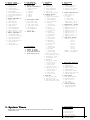
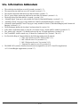
2. Zone Configuration
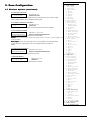
(Set Zone #)
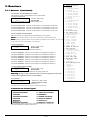
1. Zone Config.
1. Zone Type
2. Loop Type
S t a n d a r d (continued)
3. Report Codes
1. Alarm
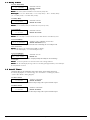
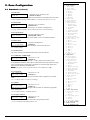
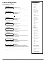
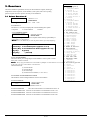
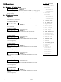
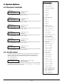
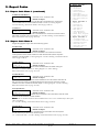
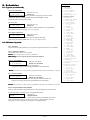
2.1.8.3 Bell 2
2. Trouble
Z## BELL 2
3. Bypass
Selections: Yes / No
4. Cancel
YES 0=NO 1=YES
Default: Yes
5. Restore
Enable this option for the SMDC to activate a steady output from Bell 2
4. Zone Name
when this zone initiates an alarm condition. (see 1.2 Cutoff Times / wiring diagram).
5. Loop Response
6. Entry Delay
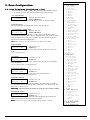
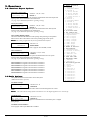
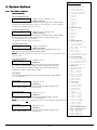
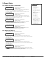
2.1.8.4 Bell 2 Pulse
7. Zone Features
Z## BELL 2 PULSE
Selections: Yes / No
1. Silent Day/
NO 0=NO 1=YES
Audible Night
Default: No
2. Telephone
Enable this option for the SMDC will activate a pulsed output from Bell 2
3. Radio
when this zone initiates an alarm condition. (see 1.2 Cutoff Times / wiring diagram).
4. Bypass Allowed
N o t e : 2.1.8.3 Bell 2 output must be programmed as YES for this Pulse Bell option to function. 5. Shunt Allowed
6. Display Armed
7. Walk Test
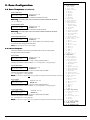
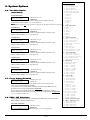
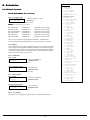
2.1.8.5 Relay 1
8. Monitor Mode
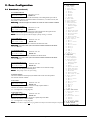
Z## RELAY 1
Selections: Yes / No
9. Auto Walk at Arm
NO 0=NO 1=YES
Default: No
8. Zone Outputs
Enable this option for the SMDC to activate Relay 1 when this zone initiates an alarm
1. Bell 1
condition. (see 1.2 Cutoff Times / wiring diagram).
2. Bell 1 Pulse
3. Bell 2
2.1.8.6 Relay 2
4. Bell 2 Pulse
Z## RELAY 2
5. Relay 1
Selections: Yes / No
6. Relay 2
NO 0=NO 1=YES
Default: No
7. PGM 1
Enable this option for the SMDC to activate Relay 2 when this zone initiates an alarm
8. PGM 2
condition. (see 1.2 Cutoff Times / wiring diagram).
9. PGM 3
9. Alarm Verify
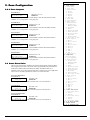
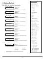
2.1.8.7 PGM 1
2. Templates
Z## PGM 1
Selections: Yes / No
(Set Zone Type)
NO 0=NO 1=YES
1. Loop Response
Default: No
2. Zone Features
Enable this option for the SMDC to activate PGM 1 when this zone initiates an alarm
1. Silent Day/
condition. (see 1.2 Cutoff Times / wiring diagram).
Audible Night
2. Telephone
2.1.8.8 PGM 2
3. Radio
Z## PGM 2
Selections: Yes / No
4. Bypass Allowed
NO 0=NO 1=YES
Default: No
5. Shunt Allowed
6. Display Armed
Enable this option for the SMDC to activate PGM 2 when this zone initiates an alarm
7. Walk Test
condition. (see 1.2 Cutoff Times / wiring diagram).
8. Monitor Mode
9. Auto Walk at Arm
2.1.8.9 PGM 3
3. Zone Outputs
Z## PGM 3
Selections: Yes / No
1. Bell 1
NO 0=NO 1=YES
Default: No
2. Bell 1 Pulse
Enable this option for the SMDC to activate PGM 3 when this zone initiates an alarm
3. Bell 2
4. Bell 2 Pulse
condition. (see 1.2 Cutoff Times / wiring diagram).
5. Relay 1
6. Relay 2
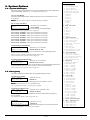
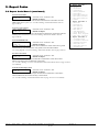
2.1.9 Alarm Verify
7. PGM 1
Z## ALARM VERIFY
Selections: Yes / No
8. PGM 2
NO 0=NO 1=YES
Default: No
9. PGM 3
Enabling this option will help in the reduction of false alarms in that the SMDC will
3. Cross Zone Pairs
recognize an alarm state on this zone and will then start a timer “window” of 60 seconds
1. Cross Zone Pair 1
1. Zone A
and must recognize subsequent alarm activation from the same circuit within the
2. Zone B
“window” before the panel will initiate an actual alarm condition.
2. Cross Zone Pair 2
N o t e : This feature can’t be used for any UL Listed application.
1. Zone A
2. Zone B
3. Cross Zone Timer
4. # of Shunt Alarms
5. Shunt Period
6. # of Expander Bds.
2. Zone Configuration
2.1
Optex Inc. - 1845 W 205th St. - Torrance, Ca. 90501 - 800-966-7839
SMDC-16 Program Manual
3440-0252 A4