1
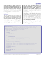
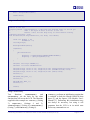
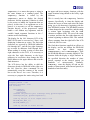
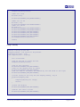
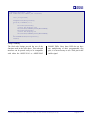
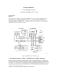
Engineer-to-Engineer Note
a
EE-219
Technical notes on using Analog Devices DSPs, processors and development tools
Contact our technical support at [email protected] and at [email protected]
Or visit our on-line resources http://www.analog.com/ee-notes and http://www.analog.com/processors
Connecting Character LCD Panels to ADSP-21262 SHARC® DSPs
Contributed by Brian M.
Introduction
This document contains example code and
hardware to interface an ADSP-21262 SHARC
DSP to a Hitachi HD44780-compatible character
LCD driver. The specific module used in this
example is an Optrex DMC-16128, which has a
16x1 character dot matrix LCD controlled by the
HD44780 driver.
A character LCD module interfaced to the DSP
can prove to be a very useful tool. In addition to
providing a user interface, the character device
can be used as a real-time debugging interface.
Using the character device to print the function
currently executing (or the state of buffers while
running) is a viable alternative to halting the
processor to check these states when using an
emulator.
Hardware Interface
The critical control signals on the LCD driver are
constrained by timing specifications that are
slow. They are too slow to be used with the
Parallel Port. However, using software to control
general-purpose flags, it is possible to generate
the necessary waveforms. This method will work
for any DSP that provides at least 11 bidirectional programmable flags (in the SHARC®
family of DSPs, the ADSP-21065, ADSP-21161,
and ADSP-21262 provide enough programmable
flags to implement this interface). This will allow
both reading and writing capabilities with an 8bit interface. (The HD44780 compatible drivers
Rev 1 – December 16, 2003
can also operate with a 4-bit interface if fewer
general-purpose flag pins are available.)
Figure 1. Hardware Interface
On the ADSP-21262 SHARC DSP, the Parallel
Port pins are multiplexed with the generalpurpose flag pins. Therefore, any access to the
Parallel Port also disturbs the LCD interface. To
avoid this problem, it is necessary to use one of
the DAI pins as a general-purpose flag, so that
the enable signal to the LCD will never be
changed unintentionally.
As shown in Figure 1, the final interface
implementation requires no glue logic. Each of
the 11 control pins for the HD44780 driver are
connected to a unique programmable flag pin
(when connecting to the ADSP-21262 SHARC
DSP, connect the E pin of the HD44780 to the
DAI pin being used a programmable flag, as
described above).
Copyright 2003, Analog Devices, Inc. All rights reserved. Analog Devices assumes no responsibility for customer product design or the use or application of
customers’ products or for any infringements of patents or rights of others which may result from Analog Devices assistance. All trademarks and logos are property
of their respective holders. Information furnished by Analog Devices Applications and Development Tools Engineers is believed to be accurate and reliable, however
no responsibility is assumed by Analog Devices regarding technical accuracy and topicality of the content provided in Analog Devices’ Engineer-to-Engineer Notes.
a
For the power interface, SHARC EZ-KIT Lite™
development boards provide pins for both a 5V
and Ground, which can be connected to the Vdd
and Vss pins of the LCD module, respectively.
For the Vee connection, use a variable
potentiometer to control the contrast of the LCD,
or simply ground Vee for maximum contrast.
Software
The most important step in developing the
software for this LCD controller is to emulate the
hold times necessary to communicate via the
interface. This can be done using “NOP” loops or
the timer. This example uses “NOP” loops. The
entirety of the code to access the LCD as
described in this document is included, along
with a VisualDSP++® project file.
Since this device will handle characters and
strings, it is most useful to develop the code to
interface to the LCD module using the C
language. The code fragments contained in this
document are in C, and are compiled using the
VisualDSP++ development suite version 3.0
(service pack 1).
Code Listings 1 and 2 show the code necessary
to read from and write to the device. Note that in
most cases, it is necessary to wait for the device
to be ready before performing an actual read or
write. Part of the call to the read and write
function is a Boolean variable (bftest - Busy Flag
Test), indicating this requirement.
At the end of this document is a complete code
listing that contains the minor functions called
from the listings presented here.
//Read from the LCD
//Inputs passed - RegisterSelect = Indicates the desired state of the RS pin
//
bftest = wait for the busy flag to clear before writing
//Outputs returned - the byte of data read from the LCD
int readFromLCD(int RegisterSelect, int bftest)
{
const int ReadWrite = 1;
int data,
busyflag = 1;
if(bftest)
{
while(busyflag)
{
busyflag = readFromLCD(LCDNORS,NOWAITFORBF);
busyflag = ((busyflag&0x80)>>7);
}
}
asm("bit clr flags 0x5400AAAA;");
asm("r0=flags; r0=r0 or %0; flags=r0;"::"d" (RegisterSelect<<26):"r0");
asm("r0=flags; r0=r0 or %0; flags=r0;"::"d" (ReadWrite<<28):"r0");
nanosec(1);
SRU(HIGH,DAI_PB15_I);
nanosec(3);
asm("r0=flags; r1=0x5555; %0=r0 and r1;":"=d" (data)::"r0","r1");
SRU(LOW,DAI_PB15_I);
nanosec(1);
Connecting Character LCD Panels to ADSP-21262 SHARC® DSPs (EE-219)
Page 2 of 11
a
data = despreadData(data);
return data;
}
Listing 1. readFromLCD()
//Write to the LCD
//Inputs passed - RegisterSelect = Indicates the desired state of the RS pin
//
data = the byte of data to write to the lcd
//
bftest = wait for the busy flag to clear before writing
//Outputs returned - none
void writeToLCD(int RegisterSelect, int data, int bftest)
{
const int Enable = 30,
ReadWrite = 0;
int busyflag=1;
data=spreadData(data);
if(bftest)
{
while(busyflag)
{
busyflag = readFromLCD(LCDNORS,NOWAITFORBF);
busyflag = ((busyflag&0x80)>>7);
}
}
asm("bit set flags 0xAAAA;");
asm("bit clr flags 0x54005555;");
asm("r0=flags; r0=r0 or %0; flags=r0;"::"d" (RegisterSelect<<26):"r0");
asm("r0=flags; r0=r0 or %0; flags=r0;"::"d" (ReadWrite<<28):"r0");
asm("r0=flags; r0=r0 or %0; flags=r0;"::"d" (data):"r0");
nanosec(1);
SRU(HIGH,DAI_PB15_I);
nanosec(3);
SRU(LOW,DAI_PB15_I);
nanosec(1);
return;
}
Listing 2. writeToLCD()
Two
functions,
readFromLCD()
and
writeToLCD(), are the basis for any other
function that will access the LCD. The functions
supplied in this example are: lcdinit() (Listing
3), lcdprintf() (Listings 4 and 5),
lcdshiftright() (Listing 6), lcdshiftleft()
(Listing 7), and lcdblink() (Listing 8).
lcdInit() performs an initialization routine that
is outlined in both the Hitachi HD44780 data
sheet [2] and the Optrex LCD Module User’s
Manual [3]. Performing this initialization may
not always be necessary, but using it will
guarantee that the LCD is in its initial state
before any commands are set.
Connecting Character LCD Panels to ADSP-21262 SHARC® DSPs (EE-219)
Page 3 of 11
a
lcdprintf() is a macro that parses a string in
the same manner as a standard printf. The
lcdprint() function is called by the
lcdprintf() macro to display the desired
characters, and the sprintf() function is called
by the macro to handle the arguments that are
passed. At this time, if no arguments are to be
passed, it is necessary to call the lcdprint()
function directly, as the preprocessor cannot
handle a call without any arguments, and the
variable length argument functions in the C
runtime are not functioning.
The display for the 16x1 character LCD of the
DMC-16128 must be accessed as 2 lines, each
displaying 8 characters at a time. The first eight
characters are accessed by DD-RAM addresses
0x0 through 0x27, and the last eight characters
are accessed by addresses 0x40 through 0x67.
When reading or writing a string of more than
eight characters to the LCD, it is necessary to
write the first eight characters to the lower
addresses in succession, then change the DDRAM address to the upper address and write the
final characters.
The LCD driver has the ability to shift the
characters already in DD-RAM to the right or to
the left. However, these commands do not
automatically wrap the contents of the second
line to the first or vice versa. Therefore, it is
necessary to program the entire string into both
the upper and lower memory locations, with the
upper locations being shifted to the left by eight
locations.
This is exactly how the lcdprint() function
operates. Specifically, it clears the display and
returns the cursor to home and writes the entire
string (up to 40 characters), beginning with the
first DD-RAM location. The DD-RAM location
is then changed to the second line, and the string
is written again beginning with the ninth
character at address 0x40. The rest of the string
is written, and then the first eight characters are
written beginning at address 0x60. This method
allows wrapping from the right half of the LCD
to the left, and vice versa.
The final three functions supplied are effects on
the display, and do not change the DD-RAM
contents.
As
their
names
suggest,
lcdshiftleft() and lcdshiftright() shift
the DD-RAM addresses currently displayed. The
function shifts the display a single character in
the specified direction the number of times
passed, repeated at the interval passed (in
hundreds
of
microseconds).
Similarly,
lcdblink() turns the display off and on, the
number of times passed, at the interval passed (in
hundreds of microseconds).
//Initialize the LCD as described in the HD44780 Datasheet
//Inputs passed - none
//Outputs returned - none
void initLCD()
{
int readbyte,
dummybyte,
flagvalues;
//Handle the parallel port interrupt using ppInterruptVector
interrupt(SIG_PP, ppInterruptVector);
//Set up DAI pin 15 as an output that is low
SRU(LOW,DAI_PB15_I);
SRU(LOW,PBEN15_I);
//Set up the DSP to access the LCD
Connecting Character LCD Panels to ADSP-21262 SHARC® DSPs (EE-219)
Page 4 of 11
a
setupForLCD(&flagvalues);
//Wait for 15 ms
microsec(150);
writeToLCD(LCDNORS,0x30,NOWAITFORBF);
//Wait for 4.1 ms
microsec( 41);
writeToLCD(LCDNORS,0x30,NOWAITFORBF);
//Wait for 100 us
microsec(1);
writeToLCD(LCDNORS,0x30,NOWAITFORBF);
writeToLCD(LCDNORS,0x38,NOWAITFORBF);
writeToLCD(LCDNORS,0x08,WAITFORBF);
writeToLCD(LCDNORS,0x01,WAITFORBF);
writeToLCD(LCDNORS,0x07,WAITFORBF);
writeToLCD(LCDNORS,0x0C,WAITFORBF);
finishedWithLCD(&flagvalues);
return;
}
Listing 3. initLCD()
//Print a string to the LCD
//Inputs passed - the string to be printed.
//Outputs returned - none
void lcdprint(char * display)
{
int i,flagvalues;
//Set up the DSP to access the LCD
setupForLCD(&flagvalues);
//Set up the interface
writeToLCD(LCDNORS,0x3C,WAITFORBF);
//Turn on the display with no cursor
writeToLCD(LCDNORS,0x0C,WAITFORBF);
//Set the mode to increment the address by one and shift to the right
writeToLCD(LCDNORS,0x06,WAITFORBF);
//If the string is too long for the display memory, say so
if(strlen(display)>40)
{
lcdprint("String too long");
return;
}
//Clear the display
writeToLCD(LCDNORS,0x01,WAITFORBF);
//Return the cursor to home
writeToLCD(LCDNORS,0x02,WAITFORBF);
Connecting Character LCD Panels to ADSP-21262 SHARC® DSPs (EE-219)
Page 5 of 11
a
//For when the string is less than 8 characters
if(strlen(display)<=8)
{
for(i=0;i<strlen(display);i++)
{
writeToLCD(LCDRS,display[i],WAITFORBF);
}
//Shift the cursor to the last 8 chars
writeToLCD(LCDNORS,0xE0,WAITFORBF);
//Write the last 8 chars
for(i=0;i<strlen(display);i++)
{
writeToLCD(LCDRS,display[i],WAITFORBF);
}
}
//For all other cases
else
{
//Write first 8 chars
for(i=0;i<strlen(display);i++)
{
writeToLCD(LCDRS,display[i],WAITFORBF);
}
//Shift the cursor to the last 8 chars
writeToLCD(LCDNORS,0xC0,WAITFORBF);
//Write the last 8 chars
for(i=0;i<(strlen(display)-8);i++)
{
writeToLCD(LCDRS,display[(i+8)],WAITFORBF);
}
//Shift the cursor to the last 8 chars
writeToLCD(LCDNORS,0xE0,WAITFORBF);
//Write the last 8 chars
for(i=0;i<8;i++)
{
writeToLCD(LCDRS,display[i],WAITFORBF);
}
}
finishedWithLCD(&flagvalues);
return;
}
Listing 4. lcdprint()
#define lcdprintf(sting,...) sprintf(sting,sting,__VA_ARGS__);\
lcdprint(sting);
Listing 5. lcdprintf()
Connecting Character LCD Panels to ADSP-21262 SHARC® DSPs (EE-219)
Page 6 of 11
a
//Shift the contents of the LCD to the left
//Inputs passed - number of times to repeat the shift
//
- interval between the shifts
//Outputs returned - none
void lcdshiftleft(int number,int interval)
{
int i,flagvalues;
//Set up the DSP to access the LCD
setupForLCD(&flagvalues);
for(i=0;i<number;i++)
{
microsec(interval);
//Write the shift left command
writeToLCD(LCDNORS,0x18,WAITFORBF);
}
finishedWithLCD(&flagvalues);
return;
}
Listing 6. lcdshiftleft()
//Shift the contents of the LCD to the right
//Inputs passed - number of times to repeat the shift
//
- interval between the shifts
//Outputs returned - none
void lcdshiftright(int number,int interval)
{
int i,flagvalues;
setupForLCD(&flagvalues);
for(i=0;i<number;i++)
{
microsec(interval);
//Write the shift right command
writeToLCD(LCDNORS,0x1C,WAITFORBF);
}
finishedWithLCD(&flagvalues);
return;
}
Listing 7. lcdshiftright()
//Blink the contents of the LCD
//Inputs passed - number of times to blink
//
- Duration that the LCD is on/off
Connecting Character LCD Panels to ADSP-21262 SHARC® DSPs (EE-219)
Page 7 of 11
a
//Outputs returned - none
void lcdblink(int number,int interval)
{
int i,flagvalues;
setupForLCD(&flagvalues);
for(i=0;i<number;i++)
{
microsec(interval);
//Turn the display off
writeToLCD(LCDNORS,0x08,WAITFORBF);
microsec(interval);
//Turn the display on
writeToLCD(LCDNORS,0x0C,WAITFORBF);
}
finishedWithLCD(&flagvalues);
return;
}
Listing 8. lcdblink()
The final code listings provide the rest of the
functions used in the code above. This code and
interface can be ported easily to be compatible
with either the ADSP-21161 or ADSP-21065
SHARC DSPs. Since these DSPs do not have
any multiplexing of their programmable flag
pins, it is not necessary to use a DAI pin for the
enable signal.
Connecting Character LCD Panels to ADSP-21262 SHARC® DSPs (EE-219)
Page 8 of 11
a
Appendix
//Pause for a multiple of 100 us
//Inputs passed - duration in units of 100 us
//Outputs returned - none
void microsec(int duration)
{
int i;
for(i=0;i<duration;i++)
{
asm("lcntr=20000, do (pc,1) until lce; \
nop;");
}
return;
}
//Pause for a multiple of 100 ns
//Inputs passed - duration in units of 100 ns
//Outputs returned - none
void nanosec(int duration)
{
int i;
for(i=0;i<duration;i++)
{
asm("lcntr=20, do (pc,1) until lce; \
nop;");
}
return;
}
//Set up the DSP to access the LCD
//Inputs passed - Pointer to location to save the current value of the flags
register
//Outputs returned - none
void setupForLCD(int * flagvalues)
{
int dummy;
asm("%0=flags;":"=d" (*flagvalues));
asm("flags = 0xA8000000;");
asm("flags = 0xA8000000;");
REG(SYSCTL)|=PPFLGS;
SRU(LOW,DAI_PB15_I);
return;
}
//Restore the DSP to the state before accessing the LCD
//Inputs passed - Pointer to the location which contains the saved value of the
flags register
//Outputs returned - none
void finishedWithLCD(int * flagvalues)
{
Connecting Character LCD Panels to ADSP-21262 SHARC® DSPs (EE-219)
Page 9 of 11
a
int dummy;
SRU(LOW,DAI_PB15_I);
SRU(LOW,PBEN15_I);
REG(SYSCTL)&=(0xFFFFFFFF-PPFLGS);
asm("flags=%0;"::"d" (*flagvalues));
asm("flags=%0;"::"d" (*flagvalues));
return;
}
//Spread a byte of data to match the FLAGS register
//Inputs passed - data = byte of data to spread
//Outputs returned - the 2-byte equivalent of the input
int spreadData(int data)
{
int i,
mask=0xff;
for(i=7;i>0;i--)
{
mask = mask >> 1;
data = (mask&data)|(((0xffffffff-mask)&data)<<1);
}
return data;
}
//Unspread a byte of data to match the FLAGS register
//Inputs passed - data = byte of data to unspread
//Outputs returned - the 2-byte equivalent of the input
int despreadData(int data)
{
int i,
newdata=0,
mask=1;
for(i=0;i<8;i++)
{
newdata |= (mask&data);
mask <<= 1;
data >>= 1;
}
return newdata;
}
Listing 9. Other useful functions.
Connecting Character LCD Panels to ADSP-21262 SHARC® DSPs (EE-219)
Page 10 of 11
a
References
[1] How to Interface an LCD to the 21xx and 2106x Family DSP’s (EE-37). 09/97. Analog Devices Inc.
[2] Hitachi HD44780U (LCD-II) Datasheet. Rev. 0.0. 09/99. Hitachi, Ltd.
[3] Optrex Dot Matrix Character LCD Module User’s Manual. Optrex Corp.
Document History
Revision
Description
Rev 1 – December 16, 2003
by Brian M.
Initial Version.
Connecting Character LCD Panels to ADSP-21262 SHARC® DSPs (EE-219)
Page 11 of 11