1
DT-ROBOT
Line Follower Base
Trademarks & Copyright
AT, IBM, and PC are trademarks of International Business Machines Corp.
Pentium is a registered trademark of Intel Corporation.
Windows is a registered trademark of Microsoft Corporation.
CodeVisionAVR is copyright by Pavel Haiduc, HP InfoTech s.r.l.
Table Of Contents
1
Introduction...............................................................................................
1.1
DT-ROBOT LINE FOLLOWER BASE Specification................................
1.2
Suggested System......................................................................................
1.3
DT-ROBOT LINE FOLLOWER BASE Movements...................................
1.4
Line Following Algorithm...........................................................................
3
3
3
4
4
2
Operating DT-ROBOT LINE FOLLOWER BASE..........................................
2.1
Default Tester Program.............................................................................
2.2
DT-ROBOT LINE FOLLOWER GUI...........................................................
2.2.1
COM Setting (A).........................................................................................
2.2.2
Connection Status (B).................................................................................
2.2.3
Test Connection (C)....................................................................................
2.2.4
Track Mode (D)...........................................................................................
2.2.5
Raw Data (E)...............................................................................................
2.2.6
Track Threshold (F).....................................................................................
2.2.7
Digital Data (G).........................................................................................
2.2.8
Sensor (H)....................................................................................................
2.2.9
Left Motor Action (I)...................................................................................
2.2.10 Left Motor Speed (J).................................................................................
2.2.11 Right Motor Action (K)...............................................................................
2.2.12 Right Motor Speed (L)...............................................................................
2.2.13 Send Setting to DT-ROBOT (M)..............................................................
2.2.14 DT-ROBOT LINE FOLLOWER Model (N)...............................................
5
5
7
7
7
8
8
8
8
8
8
8
8
8
8
9
9
3
Line Following Program Routines............................................................
3.1
LCD Initialization.........................................................................................
3.2
Send Byte to LCD.......................................................................................
3.3
Display Message to LCD...........................................................................
3.4
Display Decimal to LCD............................................................................
3.5
Display Binary to LCD...............................................................................
3.6
Move Cursor Position.................................................................................
3.7
Read ADC....................................................................................................
3.8
DT-ROBOT LINE FOLLOWER BASE Initialization.................................
3.9
Left Motor Control......................................................................................
3.10
Right Motor Control...................................................................................
9
9
9
10
10
10
10
10
11
11
11
4
DT-ROBOT LINE FOLLOWER BASE Hardware...........................................
4.1
DT-ROBOT LINE FOLLOWER BASE Component Layout.....................
4.2
Connectors and Components Functions...................................................
12
12
13
5
Testing Procedure.....................................................................................
14
Attachment
A.
B.
DT-ROBOT LINE FOLLOWER BASE Schematics....................................
DT-ROBOT LINE FOLLOWER BASE Parts Explanation.......................
2
15
16
1.
INTRODUCTION
A line-following robot, also called line follower, is very common and often
made by robot hobbyists. A lot of robotic competitions are in the form of line
following race. The line or path followed is usually a dark line on a bright
surface or vice versa. The robot detects the line by measuring the intensity of
light reflected from the surface of its path. The intensity of light reflected by
dark surface is less than the light reflected from brighter colored surface.
DT-ROBOT LINE FOLLOWER BASE is a robot controller module suitable as a
learning tools about the line follower robot for beginner to advanced
programming level.
For beginner level, DT-ROBOT LINE FOLLOWER BASE is equipped with a
standard line following algorithm that has been tested on various models of
line following tracks, ranging from simple to difficult path. Beginner level users
can experiment with setting the parameters available in the included GUI
software.
For intermediate level, we provide a sample program of the line follower
robot that has been tested with DT-ROBOT LINE FOLLOWER BASE. The user
can learn about the robot line follower programming with the assistance from
the framework of existing programs. The user can experiment with the line
following algorithm, create or add a variety of algorithms themselves so that
their line follower robots becomes more intelligent.
For advanced level, the whole series of electronics and components of the DTROBOT LINE FOLLOWER BASE will be explained in detail so that the robot
and electronics enthusiasts can be creative and experiment freely with it. DTROBOT LINE FOLLOWER BASE could be developed for robot with different
functions, sensors, or motor movements. There are also available optional
components of DT-ROBOT LINE FOLLOWER BASE such as motors and sensors
that sold separately.
1.1.
DT-ROBOT LINE FOLLOWER BASE SPECIFICATION
DT-ROBOT LINE FOLLOWER BASE specification is as follows:
• Uses 6 x AA batteries (@1.2 – 1.5 VDC) as the power supply.
• Based on ATmega168.
• Uses SN754410 motor driver IC with dual full H-Bridge configuration and
1 A continuous current capacity for each driver.
• Equipped with 8 x 2 characters LCD.
• 2 tactile switches as inputs and 1 tactile switch for reset are available.
• Communication line uses the UART RS-232 interface.
• Input/Output pins are compatible with TTL and CMOS voltage level.
1.2.
SUGGESTED SYSTEM
Suggested system for DT-ROBOT LINE FOLLOWER BASE is:
Hardware:
• PC™ AT™ Pentium® IBM™ Compatible with COM/USB serial port.
• DVD-ROM Drive and Hard disk.
Software:
• Windows® XP operating system.
• CodeVisionAVR©.
• Program CD/DVD contents:
default.hex, default.eep, GUI folder, testing folder, CodeVisionAVR
Evaluation folder, datasheets, and DT-ROBOT Line Follower Base Manual.
3
1.3.
DT-ROBOT LINE FOLLOWER BASE MOVEMENTS
DT-ROBOT LINE FOLLOWER BASE has a driver to control two wheels driven by
motors (Differential Drive). Therefore there are at least 9 kinds of movement
can be done by the robot as shown in the following table.
Movement
1.4.
Description
Straight
Left and right motor drives forward with the same speed
Turn Left
Left and right motor drives forward with the right motor faster
than the left
Turn Right
Left and right motor drives forward with the left motor faster
than the right
Sharp Turn
Left
Left motor stops while right motor drives forward with a
certain speed
Sharp Turn
Right
Right motor stops while left motor drives forward with a
certain speed
Spin Left
Left motor drives backward and right motor drives forward
Spin Right
Left motor drives forward and right motor drives backward
Reverse
Left and right motor drives backward
Stop
Left and right motor stop
LINE FOLLOWING ALGORITHM
If the line sensor module mounted on DT-ROBOT has 4 sensors, then robot's
movements are determined by reading the results of those sensors. As an
example, if a sensor is located directly above the line then its reading will have
a value of 1 and if the sensor does not detect the line then the reading value is
0. The decisions can be taken based on sensors reading value can be seen in
the following table.
Sensor Result
Example of Decisions Taken
0110
The line is right on the middle. Robot moves straight.
0010
The line deviates slightly to the right. Robot turns right.
0011
The line deviates to the right. Robot makes sharp turn to the
right.
0001
The line is in the far right. Robot spins right.
0111
There is a possible right turn. Robot spins right.
0100
The line deviates slightly to the left. Robot turns left.
1100
The line deviates to the left. Robot makes sharp turn to the
left.
1000
The line is in the far left. Robot spins left.
1110
There is a possible left turn. Robot spins left.
1111
There is a possible crossroads. Robot moves straight.
0000
Robot is off track. Run the algorithm to get back on track.
Others
Robot moves the way it was before.
If all of the sensors does not detect the line which results in “0000”, then the
robot must run the algorithm to get back on track. There are various algorithms
4
that can be used to find the line. One simple algorithm is to store the results of
last decisions of the robot. For example if previously the robot is trying to do a
sharp turn left before getting off track, then when the line disappears the robot
can be ordered to spin left to go back to the line. Else if the robot have tried to
do a sharp right turn before getting off track, then the robot can be ordered to
spin right. If the robot is moving straight forward and the lines disappear, then
the robot can be ordered to move backward.
2.
OPERATING DT-ROBOT LINE FOLLOWER BASE
2.1.
DEFAULT TESTER PROGRAM
DT-ROBOT LINE FOLLOWER BASE is equipped with a standard line following
algorithm that has been tested on various models of line following tracks,
ranging from simple path to a difficult path. Beginner level users can
experiment by setting the parameters that are available through the included
GUI software.
The algorithm is already programmed in the robot. Inside the DVD, the default
algorithm is stored with the file name "default.hex" for the program and
"default.eep" for the initial parameters.
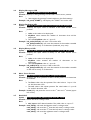
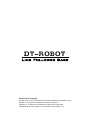
LCD
ISP
Port
ON/OFF
Switch
Battery
Terminal
RS-232
Battery
Case
Reset Button
TS1 Button
TS2 Button
At the time DT-ROBOT LINE FOLLOWER BASE was first turned on, LCD will
show a Tracking Menu marked with the string "READY" on the bottom line and
digital combination of sensors reading value on the top line.
XXXX
READY!
If TS1 Button is pressed, then DT-ROBOT LINE FOLLOWER BASE will start the
line following and LCD will show this text.
5
TRACKING
START!
To stop the line following, press TS2 Button so that DT-ROBOT LINE
FOLLOWER BASE returns to Tracking menu.
If DT-ROBOT LINE FOLLOWER BASE is in Tracking Menu, and TS2 Button is
pressed for 2 seconds, then DT-ROBOT LINE FOLLOWER BASE will switch to the
next menu which is Raw Data Menu.
SSS SSS
SSS SSS
If SENSOR PORT (J4) is connected to DT-SENSE LINE TRACKING CDS/SFH 4
SENSOR, then on this Raw Data Menu, the LCD will show sensors reading
values so that users can adjust the variable resistor on each sensor and record
the value of the sensor when it's on top of the track and off the track.
Moving from Raw Data Menu to the next menu can be done by pressing TS2
Button for 2 seconds.
The next menu is Threshold Menu which is marked with an LCD display that
resembles the following display.
XXXX
Th = YYY
Threshold or Limit is a value that is used to categorize whether the sensor is
above the line or not. For the Black Track mode which is dark lines on a
brighter surface, if the value is higher than the Limit then it will be categorized
as a line (has a value of 1). While for White Track mode, which is bright line on
a dark surface, if the value is lower than the Limit then it will be categorized
as a line (digital data has a value of 1).
Raising the Limit value can be done by pressing the TS1 Button while lowering
the Limit value can be done by pressing the TS1 Button and TS2 Button
simultaneously.
The Limit value will be stored in the DT-ROBOT LINE FOLLOWER BASE
EEPROM if the user switches to the next menu by pressing TS2 Button for 2
seconds.
The next menu is the Track Mode Menu which is marked with an LCD display
that resembles the following display.
Black
Track
On the Track Mode Menu, the user can decide whether the line that will be
passed by the DT-ROBOT LINE FOLLOWER BASE is in the Black Track
category, which is a dark line in a bright surface or White Track which is a
bright line on a dark surface.
6
Changing the track mode can be done by pressing TS1 Button. Track mode will
be saved on DT-ROBOT LINE FOLLOWER BASE EEPROM if the user switches to
the next menu by pressing TS2 Button for 2 seconds.
2.2.
DT-ROBOT LINE FOLLOWER BASE GUI
To simplify the experiment of setting the provided line following algorithm
parameters, the DT-ROBOT LINE FOLLOWER BASE pack also includes a GUI
software, “DT-ROBOT-LINE-FOLLOWER-GUI”. To set the parameters stored in
DT-ROBOT LINE FOLLOWER BASE, connect DT-ROBOT LINE FOLLOWER BASE
with a PC through UART communication using the supplied serial cable (UART
communication parameters can be seen on the COM Settings).
The following is the interface of the GUI as well as explanations of its functions.
A
B
C
E
G
F
D
H
N
K
I
J
L
M
2.2.1 COM Setting (A)
With this button, the user can select the Serial / COM port. Other parameters
of the UART communication used are as follows:
• 115200 bps
• 8 data bits
• 1 stop bit
• no parity bit
• no flow control
2.2.2 Connection Status (B)
This section displays the connection status between the PC and DT-ROBOT LINE
FOLLOWER BASE. If the connection is successful then a green colored
“Connected to DT-ROBOT” text will appear. And if the connection fails, then a
red colored “Not Connected to DT-ROBOT” text will appear. During parameter
update, if the update is successful then “Parameter update success !” will
appear for 1 second.
7
2.2.3 Test Connection (C)
This section is used to test the connection between PC and DT-ROBOT LINE
FOLLOWER BASE. The test results will be displayed on the Connection Status
section. When this button is pressed, the GUI software will read and display
the track mode and threshold settings stored in DT-ROBOT LINE FOLLOWER
BASE.
2.2.4 Track Mode (D)
This section is used to set the track mode. Two available track modes are Black
Track which is a dark line on a bright surface or White Track which is a bright
line on a dark surface.
2.2.5 Raw Data (E)
When DT-ROBOT LINE FOLLOWER BASE is connected to PC, this section will
display sensors readings values.
2.2.6 Track Threshold (F)
This section is used to set the Limit value which decides whether the sensor
reading value is categorized as a line or not. For Black Track mode, a value
higher than the Limit will be categorized as a line (has a value of 1). While for
White Track mode, a value lower than the Limit will be categorized as a line
(digital data has a value of 1).
2.2.7 Digital Data (G)
When DT-ROBOT LINE FOLLOWER BASE is connected to PC, this section will
display the comparison results of Raw Data and Track Threshold.
2.2.8 Sensor (H)
This section is used to choose the sensor reading digital value combinations. If
DT-ROBOT LINE FOLLOWER BASE is connected to PC, when a combination is
selected (via mouse or the "S" key on keyboard), it will display the
corresponding action setting stored in DT-ROBOT LINE FOLLOWER BASE. The
setting result will be displayed on the Left/Right Motor Action section along
with each motor's speed setting.
2.2.9 Left Motor Action (I)
This section is used to set the action the left motor will do for the selected
digital value combination on Sensor section. The available actions are Forward
(drive forward), Stop , or Reverse (drive backward).
2.2.10 Left Motor Speed (J)
This section is used to set the left motor speed (PWM value) for the selected
digital value combination on Sensor section. The allowed value is ranging from
0 to 1023. The bigger the value, the faster the left motor will spin.
2.2.11 Right Motor Action (K)
This section is used to set the action the right motor will do for the selected
digital value combination on Sensor section. The available actions are Forward
(drive forward), Stop , or Reverse (drive backward).
2.2.12 Right Motor Speed (L)
This section is used to set the right motor speed (PWM value) for the selected
digital value combination on Sensor section. The allowed value is ranging from
0 to 1023. The bigger the value, the faster the right motor will spin.
8
2.2.13 Send Setting to DT-ROBOT (M)
This button is used to send the Mode Track, Track Threshold, Left/Right Motor
Action, and Speed parameter settings from PC to DT-ROBOT LINE FOLLOWER
BASE. The above parameters will be sent to DT-ROBOT LINE FOLLOWER BASE
when the software has been connected to DT-ROBOT LINE FOLLOWER BASE
and the "Send Setting to DT-ROBOT" button is pressed. If the parameter
update is successful then “Parameter update success !” will appear for 1
second on Connection Status section.
2.2.14 DT-ROBOT LINE FOLLOWER Model (N)
This section is used to give an illustration for the possible positions of DTROBOT LINE FOLLOWER BASE toward the line, based on the selected digital
value combination on Sensor section.
3.
LINE FOLLOWING PROGRAM ROUTINES
For intermediate level, we provide a sample program of the line follower
robot that has been tested with DT-ROBOT LINE FOLLOWER BASE. Users can
learn about the line follower robot programming with the assistance from the
framework of existing program. Users can experiment with the line following
algorithm, create or add a variety of algorithms themselves so that their line
follower robots become more intelligent.
In the DVD, the program example is stored in ”testing” folder. The program
can be opened using CodeVisionAVR evaluation version.
The program has 3 main files, which is : "testing.c" that contains the line
following main algorithm, "LCDRoutine.c" that contains LCD related functions,
and "OtherRoutine.c" that contains other functions such as directional control
and motor speed (PWM values).
There are several procedures and functions on the program that can be used to
help the user in programming. The following are some of the procedures and
functions used in "LCDRoutine.c" and "OtherRoutine.c":
3.1
LCD Initialization
Syntax : void initlcd(void);
Function : Initializes LCD.
Desc.
:
➢ Call this procedure to perform the LCD initialization process. It's
only needed to be performed once at the beginning of program.
➢ This procedure is used by the initMain procedure.
Example : initlcd();
3.2
Send Byte to LCD
Syntax : void putlcd(unsigned char moda, unsigned char comm);
Function : Sends 1 byte Command or Data to LCD.
Desc.
:
➢ The valid moda value is 0 if LCD command is sent and 1 if LCD
data is sent.
➢ The comm value is the value of the sent LCD command or data.
➢ The list of LCD command and data can be seen in the LCD
datasheet.
Example : putlcd(0,0x01); will clear the LCD screen.
9
3.3
Display Message to LCD
Syntax : void lcd_putsf(flash unsigned char *str);
Function : Displays a string/message on the LCD's current cursor position.
Desc.
:
➢ *str contains the message's initial address in the flash memory.
Example : lcd_putsf("START!"); will display the "START!" text on the LCD.
3.4
Display Decimal to LCD
Syntax : void lcd_putInt(unsigned int value,unsigned char dispNum);
Function : Displays the input values in decimal to the LCD's current cursor
position.
Desc.
:
➢ value is the value to be displayed.
➢ dispNum value contains the number of characters that will be
displayed.
➢ The valid dispNum value is 1 up to 5.
Example : lcd_putInt(1234,4); will write 1234 on the LCD.
lcd_putInt(number,3); will write the contents of the number variable
on the LCD as many as 3 characters (hundreds, tens, units).
3.5
Display Binary to LCD
Syntax : void lcd_putBin(unsigned char value,unsigned char dispNum);
Function : Displays the input values in binary to the LCD's current cursor
position.
Desc.
:
➢ value is the value to be displayed.
➢ dispNum value contains the number of characters to be
displayed.
➢ The valid dispNum value is 1 up to 8.
Example : lcd_putBin(12,4); will write 1100 on the LCD.
lcd_putInt(number,5); will write the contents of the number variable
on the LCD as many as 5 characters.
3.6
Move Cursor Position
Syntax : void locate(unsigned char lines, unsigned char cols);
Function : Arranges the cursor position so that it will be placed in a certain line
and column.
Desc.
:
➢ The lines value is the line position. The valid value is 1 up to 2 for
an 8x2 character LCD.
➢ The cols value is the column position. The valid value is 1 up to 8
for an 8x2 character LCD.
Example : locate(1,1); will place the cursor in the 1st line and 1st column (upper
left corner).
3.7
Read ADC
Syntax : unsigned char read_adc(unsigned char adc_input);
Function : Reads the sensor voltage value.
Desc.
:
➢ adc_input is ADC channel number. The valid value is 4 up to 7.
Example : read_adc(4); will read the leftmost sensor's voltage value.
read_adc(5); will read the 2nd from the left sensor's voltage value.
read_adc(6); will read the 3rd from the left sensor's voltage value.
read_adc(7); will read the rightmost sensor's voltage value.
10
3.8
DT-ROBOT LINE FOLLOWER BASE Initialization
Syntax : void initMain(void);
Function : Initializes all I/O ports and DT-ROBOT LINE FOLLOWER BASE
peripherals including LCD.
Desc.
:
➢ Call this procedure to perform the LCD initialization process. It's
only needed to be performed once at the beginning of program.
Example : initlMain();
3.9
Left Motor Control
Syntax : void motorKiri(unsigned char arah,unsigned int speed);
Function : Arranges the speed and spin direction of the left motor.
Desc.
:
➢ arah can have a value of 0 for forward, 1 for reverse, or 2 for
stop.
➢ speed is the speed of the motor (PWM value). The valid value is 0
to 1023. The greater the speed value the faster the motor spins.
Example : motorKiri(0,500); will command the left motor to drive forward with
a PWM value of 500.
3.10
Right Motor Control
Syntax : void motorKanan(unsigned char arah,unsigned int speed);
Function : Arranges the speed and spin direction of the right motor.
Desc.
:
➢ arah can have a value of 0 for forward, 1 for reverse, or 2 for
stop.
➢ speed is the speed of the motor (PWM value). The valid value is 0
to 1023. The greater the speed value the faster the motor spins.
Example : motorKanan(2,0); will command the right motor to stop.
11
4.
DT-ROBOT LINE FOLLOWER BASE HARDWARE
4.1.
DT-ROBOT LINE FOLLOWER BASE COMPONENT LAYOUT
12
4.2.
CONNECTORS AND COMPONENTS FUNCTIONS
The J7 blue terminal is the connector for power supply.
Pin
Name
1
GND
2
Function
Ground reference for power supply input
7.2-9VDC Connected to power supply for input (7.2 – 9 Volt)
UART RS232 (J3) RJ11 connector is the connector for UART RS-232 interface.
Pin
Name
1
NC
2
Function
Not connected
SGND Ground reference
3
TX
RS-232 serial output from DT-ROBOT LINE FOLLOWER BASE
4
RX
RS-232 serial input to DT-ROBOT LINE FOLLOWER BASE
ISP HEADER (J1) header is the connector for ISP programming.
Pin
Name
1
MOSI
Connected to microcontroller's MOSI pin
2
VCC
5 volts output voltage from DT-ROBOT LINE FOLLOWER
BASE
3
NC
Not connected
5
Function
ISP_RST Connected to microcontroller's RESET circuitry
7
SCK
Connected to microcontroller's SCK pin
9
MISO
Connected to microcontroller's MISO pin
4,6,8,10
GND
Ground reference
SENSOR PORT (J4) connector is the connector for the sensor module.
Pin
Name
1
SI3
Input, connected to microcontroller's internal ADC channel 7
2
SI2
Input, connected to microcontroller's internal ADC channel 6
3
SI1
Input, connected to microcontroller's internal ADC channel 5
4
SI0
Input, connected to microcontroller's internal ADC channel 4
5
SEN
Output to turn on or off the LED on the sensor module
6
NC
Not connected
7
VCC
5 volts output voltage from DT-ROBOT LINE FOLLOWER BASE
8
Function
PGND Ground reference
M1 (J5) connector is the connector for the left motor.
Pin
Name
Function
1
M11
Output to the 1st left motor pin
2
M12
Output to the 2nd left motor pin
13
M2 (J6) connector is the connector for the right motor.
Pin
Name
Function
st
1
M21
Output to the 1 right motor pin
2
M22
Output to the 2nd right motor pin
S4 slide switch is used as an ON/OFF switch with LED PWR IND (D13) as its
indicator.
VR LCD CONTRAST (R5) is used to set the LCD contrast.
VR AIN0 ADJ (R6) is connected to AIN0. This VR can be used for Analog
Comparator Multiplexed Input.
Tactile switch RESET (S1) is connected to the reset circuitry.
Tactile switch TS1 (S2) is connected to PortD.7, can be functioned as input.
Tactile switch TS2 (S3) is connected to PortB.5, can be functioned as input.
LCD and motor driver connection can be seen in the schematics attachment.
5.
TESTING PROCEDURE
1. Connect DT-SENSE LINE TRACKING CDS/SFH 4 SENSOR or compatible
sensor circuitry to SENSOR PORT (J4) connector.
2. Connect DT-ROBOT MINI METAL GEAR HIGH SPEED MOTOR SET/DTROBOT MINI METAL GEAR MOTOR SET/DT-ROBOT PLASTIC GEAR
MOTOR I SET/DT-ROBOT PLASTIC GEAR MOTOR L SET or compatible
motors to M1 (J5) dan M2 (J6) connectors.
3. Connect power supply to J7 blue terminal (from the batteries or other
power source).
4. Turn on the DT-ROBOT LINE FOLLOWER BASE using the available ON/OFF
switch.
5. LCD will show Tracking Menu marked with the inscription "READY" on the
bottom line and digital combination of sensors reading value on the top
line.
6. Press the TS1Button so that the DT-ROBOT LINE FOLLOWER BASE will start
to perform line-following (left and/or right motor will spin).
7. Press the TS2 Button to go back to Tracking Menu.
8. Hold the TS2 Button for 2 seconds.
9. DT-ROBOT LINE FOLLOWER BASE enter the Raw Data Menu and LCD will
display the sensors reading values.
10. Place the sensor above a bright or dark surface. The sensor value will
change depend on the surface brightness level.
11. Connect DT-ROBOT LINE FOLLOWER BASE and PC using the included serial
cable.
12. Run DT-ROBOT-LINE-FOLLOWER-GUI software.
13. Set Serial Port configuration via the COM Setting button.
14. Press the Test Connection button.
15. If the connection is successful, then "Connected to DT-ROBOT" will appear
on the Connection Status section.
♦ Thank you for your confidence in using our products, if there are difficulties, questions,
or suggestions regarding this product please contact our technical support:
[email protected]
14
ATTACHMENTS
A. DT-ROBOT LINE FOLLOWER BASE SCHEMATICS
15
B. DT-ROBOT LINE FOLLOWER BASE PARTS EXPLANATION
Bolts on battery case, need to be loosened
when replacing the bracket (when using
different type of motor).
Bolts for bracket (under battery case), need
to be loosened when replacing the bracket
(when using different type of motor).
Bolts for LCD, need to be loosened when
replacing the spacer (when using different
type of motor).
Bolts for castor (upper), need to be
loosened when replacing the spacer (when
using different type of motor).
16