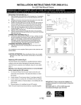
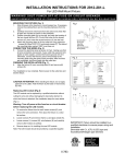
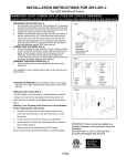
1
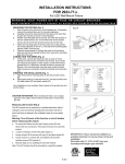
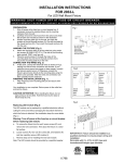
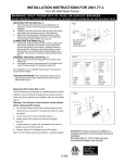
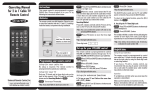
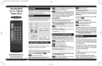
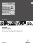
RF
MASTER DIMMER – VL-9540-MND-X FOR DIMMABLE LED/CFL/INCANDESCENT/MLV/ELV/HALOGEN/DIMMABLE FLUORESCENT
IMPORTANT:
RF Master dimmer will not work or will become damaged if wired incorrectly, and warranty will
be voided. Refer to wiring instructions provided on reverse side.
OPERATION INSTRUCTIONS
• Press once to turn lights ON at previously selected level.
• Press again to turn lights OFF.
• When lights are OFF, press and hold for 2 seconds for full brightness.
• When lights are ON, press and hold for 2 seconds until the blue LED blinks. After the preset
delay, the lights will begin fading to OFF (up to 4 minutes).
• Amber ON/OFF LED indicates that dimmer is turned on.
DIMMING LEVEL ADJUSTMENT
For maximum compatibility with different loads types, VL-9540-MND-X allows the user to set
the minimum level. Also to save on power consumption VL-9540-MND-X allows the user to set
the maximum level.
1. After installing the dimmer and restoring power, press on/off button to turn on the light.
2. Press and hold on/off button for five seconds until the blue dimmer LEDs begin to cycle
rapidly (NOTICE- after two seconds blue dimmer LEDs will start to flash indicating activation
of the delay off feature. Continue holding the ON/OFF button for three additional seconds
until the blue dimmer LEDs begin to cycle rapidly.)
3. Release the button. Dimmer will set the light to the previously saved minimum level (that
may cause the light to flicker or turn off). During initial setup, the light will set to the factory
minimum default.
4. Press either the dim or bright buttons to change the minimum level until the
light output is acceptable.
5. Press ON/OFF button. Blue dimmer LEDs will start to cycle rapidly again and the dimmer
light will go to previously saved maximum level.
6. Press either the dim or bright buttons to change the maximum level
until the light output is acceptable.
7. Press ON/OFF button, LED will flash indicating completion of programming
• NOTE – To restore the default min/max, repeat the steps above and adjust light levels to full
min/max settings by pressing dim/bright buttons until the light output no longer changes.
• NOTE - User could ignore setting max or min by pressing on/off button without changing the
dimmer level.
Rapid start feature
This feature ensures that LED/CFL lights turn on when the dimmer preset level is low. With this
setting enabled, the lights may momentarily be brighter than the preset level (less than one
second) and then dim down to the preset level.
Depending on the type of light used, this feature may not be needed.
To enable/disable the feature, turn lights on. Press and hold the on/off button for 10 seconds
until the blue dimmer LEDs flash for the third time, then release the button.
Z-Wave Device Network Installation Instructions
1.This product may be added to a new or existing Z-Wave network. This Z-Wave device has a blue
LED, which will blink when the device is not included in a Z-Wave network. The LED stops
blinking when the device is in a network.
2.To include this device in a Z-Wave network, select the command on your Z Wave controller
for inclusion (Install, Add Device, Add Node, Include Device, etc.). Then press the device ON/OFF
switch one time to include it in the network. The LED will stop blinking.
3.To exclude this device from a Z-Wave network, select the command on your Z-Wave controller
for exclusion (Uninstall, Remove Device, Remove Node, Exclude Device, etc.). Then press the
device ON/OFF switch one time to exclude it from the network. The LED will start blinking.
4.This product works with other Z-Wave products from different vendors and product categories
as part of the same network.
5.This product is a listening node and it will act as a repeater in the Z-Wave network. It will
perform the repeater function with Z-Wave products and from other Z-Wave vendors.
READ BEFORE INSTALLATION!
Switch Identification
White
White
ACCESSORY
ACCESSORY
ACCESSORY
Green
Red
INSTALLATION INSTRUCTIONS
WARNING:
• Turn OFF circuit breaker or remove fuse(s) and test that power is off before wiring.
• Never wire any electrical device with power turned on. Wiring dimmer with power on
may cause permanent damage to dimmer and void warranty.
• If you are not sure about any part of these instructions, please contact a
licensed electrician.
Green
Disconnect Switch
Black
Black
Master Control
Accessory
Troubleshooting Guide
Symptom
Possible Cause
Solution
CAUTION:
1. Use only with 120V AC 60 Hz.
2. Do not exceed maximum rating of the dimmer as indicated on the device.
3. Must be installed and used in accordance with electrical codes.
4. If a bare copper or green ground connection is not available in the wallbox, contact a
licensed electrician for installation.
5. Use only #14 or #12 copper wire rated for at least 75°C with these devices. Do not
use with Aluminum wire.
No Function. All LEDs are OFF
A) Light bulb(s) burned out
B) Circuit breaker is off or
tripped
C) Disconnect switch on the
dimmer is pulled out to the
OFF position
D) Improper wiring
E) Defective dimmer
A) Replace light bulb
B) Turn on the circuit breaker
C) Push in the disconnect
switch on the dimmer
D) Check and correct wiring
E) Replace dimmer
NOTES:
1.The RF Master Dimmer is wired directly to the light fixture.
2.The RF Master Dimmer is not compatible with standard 3-way switches.
3.For Multi-location applications (3-Way or 4-Way) the RF Accessory Dimmer(s) is used along
with one RF Master Dimmer.
4.The RF Accessory Dimmer communicates via RF signals to control the light from
more than one location.
5.For multi-location control use RF Smart Dimmer Master direct wired to the light
along with RF Accessory (VL-9540-MND-X). The RF Accessory does not require direct
connection to the light (use Association function).
6.Do not exceed the maximum load indicated in the table below.
Erratic operation or flickering
LEDs
A) Loose wiring connections
B) Low dim setting
A) Check and correct wiring
B) Set minimum brightness
to a higher level
Lights turns on after long
delay
A) Rapid start feature is
disabled
B) Low dim setting
A) Enable rapid start feature
B) Set minimum brightness to
a higher level
Functions normally using the
dimmer push buttons but not
from Z-Wave controller and
one of the blue LEDs blinks
ON and OFF about once per
second
Dimmer is not included in
Z-Wave network
Include dimmer in a Z-Wave
network using a Z-Wave
controller. Refer to Z-Wave
controller user manual for
details
Functions normally using the
Master dimmer control but
not from Z-Wave controller
and no LEDs are blinking
Problem with RF
communication on dimmer
Replace dimmer
Functions normally both locally and from a Z-Wave controller but can’t be controlled
from a dimmer accessory
switch (VL-9542-AND-X) or
other Z-Wave device
The dimmer accessory or
other Z-Wave device is not
associated with the dimmer
you wish to control
Create an association
between the dimmer
accessory or other device and
the dimmer. Refer to your
Z-Wave controller user manual
for details
Dimmer is warm to touch
after a period of time
This is normal
No action required
Catalog #
VL-9540-MND-X
Loads
Maximum Load
INC/ ELV/ FLR/ Halogen/ MLV
600W/VA
CFL/ LED
300W
Single Location Control Installation (requires one Master dimmer)
1.1
1.3
Master
1.5
1.3
1.4
1.2
Black
Black - Hot
Black
Green
Tag
Tag
White
Bare
White
White
Black To Light
Identify existing wiring (This switch will be a single-pole) and tag “Hot” wire. Use Disconnect existing switch and remove.
voltage tester as necessary to confirm “Hot” wire (Voltage will be present at the
“Hot” wire when the lights are off).
1.4
1.6
Black
Red
Connect master dimmer as shown by connecting black
wire of dimmer to tagged “Hot” wire. Red wire must
be connected to the wire that goes to the light.
TOP
Hot
Red
Black
MASTER
DIMMER
120V
Green
Ground
Neutral
Gently push dimmer into place and secure with mounting screws. Make
sure disconnect switch at bottom of master is fully pushed in
Light Fixture
White
White
Two Location Control Installation (requires one Master and one Accessory)
2.1
2.1
2.2
Red
Accessory
2.4
2.3
Red
LOCATION A
White
Black
Bare
Bare
Black
Tag
Black
Black
Tag
White
Black
White
Tag
Red
ACCESSORY
Black
Green
White
Disconnect existing switch and remove. Connect
Accessory Dimmer in Location A as shown.
NOTE: The Circuit Breaker must be turned “ON” during this step
Identify existing wiring (both existing switches will be “3-way”)
Tag common wire on both 3-Way switches (see “How to Identify and the switches must be set so that the light is OFF. Ensure
that all wires are safely separated before turning the Circuit
Common Wires” section*)
Breaker “ON.” Connect the tester between the tagged common
Master
terminal and ground in one of the boxes to determine the location
2.4
for the Accessory Dimmer. If the test indicates voltage then that
will be Location A, and will be used for the Accessory Dimmer.
Red
Black
If voltage is not present then the other 3-way location will be
Tag
Location A. NOTE: Disconnect power after this step.
Green
White
Red
Hot
Black
ACCESSORY
DIMMER
Black
Black
Black
120V
Green
Red
Traveler Wires
Black
Red
Light Fixture
Green
White
Ground
MASTER
DIMMER
White
MASTER
DIMMER
2.5
Ground
Neutral
White
White
White
LOCATION A
Three Location Control Installation (requires one Master and two Accessory dimmers)
3.1
3.1
3.2
3.2
Red
4-Way Location
White
Tag
Black
Red
Connect the second Accessory Dimmer (4-way switch) as shown.
Accessory
Red
Black
Bare
Tag
White
Green
Black
ACCESSORY
Tag
Black
White
Identify existing wiring (4-way switches) Tag common
wires on 4-Way switch. (see “How to Identify
Common Wires” section*)
Red
Green
Traveler Wires
Black
Green
White
Ground
Black
Red
Traveler Wires
Black
Black
Green
MASTER
DIMMER
ACCESSORY
DIMMER
120V
ACCESSORY
DIMMER
Red
Hot
Light Fixture
IMPORTANT! How to identify Common Wires*
Two location:
Each switch will have insulated wires connected to three terminal screws plus a
green or bare wire connected to a green terminal screw. The three terminals are
usually one dark colored screw and two light colored screws (ignore the Green
screw). Alternatively, the three screws may be the same color and one will be
marked COMMON or COM Find the wires connected to the dark or COMMON
screws. Usually these wires are black but may be red or blue. Tag these wires on
both switches to identify when wiring.
Three location:
Two of the existing switches will be 3-way. The 3-way switches will be located
at each end of the circuit with a 4-way switch in between. TAG the two 3-way
switches as in the Two Location Control section. The 4-Way switch has 4 insulated wires connected to 4 terminal screws. VERY IMPORTANT - TAG two same
color insulated wires, which are connected to screws of opposite colors.
White
Ground
Ground
Neutral
White
White
White
White
LOCATION A
White
Refer to 1.4 to push dimmers into place.
Universal Remote Control, Inc.
500 Mamaroneck Ave.
Harrison, NY 10528
(914) 835-4484
[email protected]
www.UniversalRemote.com
RFAL-DIMR-U-EN (REV. A)