1
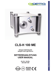
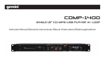
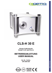
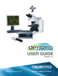
USER GUIDE v1.4 This document discusses the use and architecture of the OptiGrid® Structured Illumination System. Introduction The OptiGrid Structured Illumination System is an optical sectioning device used for high-contrast fluorescence and ultra-sharp 3D imaging. The OptiGrid Structured Illumination System consists of a paddle and a controller box. The paddle component of the system contains an optical grid that is controlled by a piezo drive for grid positioning and a DC motor drive for grid focus along the optical axis. Note: Manual versions will not have automated focus capability. The OptiGrid works together with common microscope components and is controlled by a host imaging application via a USB 2.0 communication protocol. The OptiGrid Structured Illumination System is pictured below. Figure 1: OptiGrid Structured Illumination System Table of Contents • Unpacking • Waste of Electronic and Electrical Equipment 3 3 • Safety & Symbol Definition • Service Requires Qioptiq Trained Personnel • Special Handling Instructions • Safety Standard Compliance 4 4 4 4 • What You Need to Get Started • Standard OptiGrid Components • Microscopes • Computer and CCD/Frame Grabber Requirements 5 5 6 • Installation • Application Software • OptiGrid Controller • OptiGrid Paddle • Cable Connections 7 7 7 7 8 6 • Operation • Functional Overview • Power (ON/OFF) • System Status and Error Messages • USB HID Class Communications Protocol 9 9 9 10 11 • Specifications • Electrical • Physical 12 12 13 • Global Regulatory Compliance & Certifications • Safety • Electromagnetic • Environmental/ European Regulatory Compliance 15 15 17 19 • Customer Support and Services 20 • One Year Limited Warranty 21 Qioptiq Imaging Solutions OptiGrid® Structured Illumination System User Guide V1.4 2 Unpacking Remove the OptiGrid Structured Illumination System components from the package. The system is shipped with a paddle that has windows to protect the grid from dirt while allowing light to pass through. Remove the paddle from its plastic bag by grasping the metallic paddle handle. Never grasp the paddle by touching the protective windows. Keep the windows clean and do not scratch them. Inspect all system components for any sign of damage. Contact your OptiGrid reseller if the unit appears damaged in any way. Waste of Electrical and Electronic Equipment (WEEE) This symbol on the product or on its packaging indicates that this product must not be disposed of with your other household waste. Instead, it is your responsibility to dispose of your waste equipment by handing it over to a designated collection point for the recycling of waste electrical and electronic equipment. The separate collection and recycling of your waste equipment at the time of disposal will help to conserve natural resources and ensure that it is recycled in a manner that protects human health and the environment. For more information about where you can drop off your waste equipment for recycling, please contact your local city office, your household waste disposal service or the vendor where you purchased the product. Qioptiq Imaging Solutions OptiGrid® Structured Illumination System User Guide V1.4 3 Safety / Symbol Definition Service Requires Qioptiq Trained Personnel DANGER HAZARDOUS ELECTRICAL VOLTAGE This symbol shown on the left is depicted on the back-plate of the OptiGrid Controller. It indicates the presence of electric shock hazards. The OptiGrid system components should only be opened by trained personnel. Special Handling Instructions CAUTION: The OptiGrid Controller must only be used to operate the OptiGrid paddle. Do NOT use it to operate other equipment. The GRID CONTROL OUTPUT located at the rear of the OptiGrid Controller produces voltages ranging from 40-150 V peak, DC to 1 KHz when the unit is turned on. TAKE PRECAUTION. Do NOT touch the output connector when operating the unit. Safety Standards Compliance The OptiGrid system meets the government safety regulations for electrical equipment for measurement, control, and laboratory use in North America and the European Union. In addition this product is certified for compliance to the CB Scheme, a product safety certification that is recognized in more than 30 participating countries. European Union - CE Marking: Standards IEC 61010-1 and EN 61010-1 - TUV Rheinland GS Mark US: Occupational Safety and Health Administration (OSHA) - cTUVus Marking: Standard UL61010 Canada: Standards Council of Canada (SCC) - cTUVus Marking: Standard C22.2 No. 1010 International: Certification Body Scheme (CB Scheme) - CB Certificate and Report with ALL national deviations Qioptiq Imaging Solutions OptiGrid® Structured Illumination System User Guide V1.4 4 What You Need to Get Started To set up the OptiGrid Structured Illumination System, you will need the following hardware and documentation listed and pictured below: Standard OptiGrid Components OptiGrid Structured Illumination System Controller Box OptiGrid Structured Illumination System Paddle Note: Different microscopes will require different paddles Grid Focus Cable (Motor Cable) Grid Control Cable (HI Voltage Output Cable) USB 2.0 Communication Cable Power Cord for the Controller Box UK, Euro, or North American OptiGrid Structured Illumination System User Guide (not shown) Figure 2: OptiGrid Structured Illumination System Standard Components Qioptiq Imaging Solutions OptiGrid® Structured Illumination System User Guide V1.4 5 Microscopes The OptiGrid Structured Illumination System integrates with a variety of popular brand microscopes. Contact your OptiGrid reseller to determine if a specific microscope can integrate with your OptiGrid System. Olympus IX 50, 51, 71, 81 o (Requires IX2-RFAL L-Shape Illuminator) BX 41, 51, 61 Series o (Requires BX-RFA/A Illuminator) Nikon E400, E600/FN & E80i/90i Series o (Requires D-fl/E, 6 Position Universal EpiFluorescent Attachment or DIH-M (Digital Imaging Head-M) Epi-Fluorescent Attachment or D-DH Digital Imaging Head M TE2000/E/U/S Inverted Zeiss Axiovert 200/M Axioplan 2 Imaging/MOT Leica DM 2000/2500/3000 (Requires Modified Illuminator) Computer and CCD/Frame Grabber Requirements Please contact your imaging software vendor for minimum computer system recommendations and CCD/Frame Grabber support. Qioptiq Imaging Solutions OptiGrid® Structured Illumination System User Guide V1.4 6 Installation This section explains and illustrates how to set up your OptiGrid Structured Illumination System with your microscope and computer. Complete the following steps to set up your OptiGrid Structured Illumination System and configure it for use. Application Software Refer to your imaging software user’s manual for information about how to control the OptiGrid Structured Illumination System. OptiGrid Controller The controller physical dimensions are: 9.5”[24.1cm] x 8.0”[20.3cm] x 3.5”[8.9cm]. Rubber feet are attached to the bottom of the unit to prevent skidding and allow it to be stacked on other desktop equipment that requires circulation of air. The OptiGrid Controller requires at minimum .078”[2mm] of clear air space above the unit. CAUTION: The OptiGrid Controller must only be used to operate the OptiGrid paddle. Do NOT use it to operate other equipment. Optigrid Paddle The paddle slides into the illuminator, usually replacing the field diaphragm insert. The paddle has two click stops. One stop marks the correct positioning in the illuminator’s beam-line. The other click stop marks complete removal from the beam-line. It is not required to place the paddle on the desktop when the OptiGrid is not being used. Qioptiq Imaging Solutions OptiGrid® Structured Illumination System User Guide V1.4 7 Cable Connections 1. Connect the USB 2.0 Cable between the USB 2.0 port on the Controller (1) and a USB 2.0 port on the COMPUTER (1). Note: The controller will also work on a non USB 2.0 port. 2. Connect the Grid Control Cable between the GRID CONTROL OUTPUT port on the Controller (2) and the 4 pin receptacle on the Paddle (2). 3. Connect the Grid Focus Cable between the GRID FOCUS port on the Controller (3) and the 12 pin receptacle on the Paddle (3). 4. Connect the power cord to the AC IN power inlet module on the Controller (4), and plug into local power (4). Note: For EMC compliance, operate this system with the cables provided Figure 3: OptiGrid Structured Illumination System Cable Connections Qioptiq Imaging Solutions OptiGrid® Structured Illumination System User Guide V1.4 8 Operation To following sections explain the functions of the OptiGrid Structured Illumination System. Functional Overview The OptiGrid Paddle contains a one-dimensional optical grid mounted on a piezo driven actuator and a focus motor attached to a Z-stage. The OptiGrid Controller controls both the phase and focus position of the optical grid via commands from the computer’s USB 2.0 interface. When the OptiGrid Paddle is inserted into the light path of the microscope illuminator, amplified voltage from the OptiGrid Controller is applied to the piezo crystal to change its length. The piezo crystal provides highly accurate repositioning of the grid pattern. The grid pattern is systematically projected onto the specimen and is moved perpendicularly to the grid lines across the sample. One structuredlight image consists of three split-second captures of the grid. The first image is taken at any position of the grid; the grid is then moved linearly by 1/3 of the grid period length to capture the second image, and another 1/3 to capture the third image. This typically occurs in less than one second, generating one structured-light image or optical section. Optically, the grid returns a strong signal wherever focus is sharp and a weak signal where focus is soft. The patented OptiGrid algorithm eliminates the weaker signals from above or below the primary image plane as defined by the grid. The resulting image is free of any stray light or soft focus data, and can be viewed live on your computer monitor in near real time. The lateral resolving power of your selected microscope objective is unaffected by the addition of OptiGrid. We recommend that you choose an objective lens with a high degree of spherical aberration correction and UV-transmission capability (Plan APO-Chromat is BEST). Because OptiGrid utilizes the illumination source of the host wide-field microscope, all fluorescence capabilities of that microscope are maintained. When using fluorescence with the OptiGrid System, the excitation and emission filters and dichloric mirrors should be optimized to the specific fluorophore being used. Power (ON/OFF) The power ON/OFF control is located on the front panel of the OptiGrid Controller. Qioptiq Imaging Solutions OptiGrid® Structured Illumination System User Guide V1.4 9 Factory System Status and Error Messages System status messages are displayed on the OptiGrid (OG) Liquid Crystal Display (LCD) located on the front panel of the OptiGrid Controller. Tables 1 and 2 list the standard Status and Error Messages that may be displayed on the OptiGrid LCD during the course of operation. Your imaging software provider may choose to display additional status or error messages to the OptiGrid LCD. OptiGrid System Status Messages Message Description Initializing Displayed when OG is first turned on. Wait until the message clears before operating the OG unit. Default message when no other OG messages are displayed. Default message when the host has set the OG for external DAC control of the grid phase position. Indicates that the grid focus position is at the HOME position (minimum focal setting). Indicates that the grid focus position is at the LIMIT position (maximum focal setting). Indicates that the host has set the OG for use with a “manual” (nonmotorized) paddle. Indicates that the host has set the OG for use with a “motorized” paddle (default). Indicates that a connection between the host PC and the OG has not been established. Indicates the version of firmware that is installed on the OG. OK OK, External DAC OK, Focus Home OK, Focus Limit OG Manual* OG Motorized* USB inactive Version_XX* *Note: Messages are only for OG firmware versions greater than Version 8. OptiGrid System Error Messages Message FAULT, Focus Cable FAULT, Focus Stall FAULT, Phase Stall FAULT, Piezo Cable Qioptiq Imaging Solutions Description Indicates that the Grid Focus Cable is not connected. Corrective Action: Power down and connect the Focus Cable. Restart the system. Indicates that the grid focusing mechanism is stalled. Corrective Action: Call technical support. Indicates that the grid phase mechanism is stalled. Corrective Action: Call technical support. Indicates that the Grid Control Cable is not connected. Corrective Action: Power down and connect the Piezo Cable. Restart the system. OptiGrid® Structured Illumination System User Guide V1.4 10 USB HID Class Communications Protocol Developers System developers and integrators should contact Qioptiq Imaging Solutions for the latest Communications Protocol for OptiGrid. Qioptiq Imaging Solutions 78 Schuyler Baldwin Drive Fairport, NY 14450 (585) 223-2370 [email protected] End Users Please contact your imaging software vendor for User Interface instructions. Qioptiq Imaging Solutions OptiGrid® Structured Illumination System User Guide V1.4 11 Specifications This section describes the physical characteristics of the OptiGrid Structured Illumination System, along with its recommended operating conditions. Electrical Power Requirement Voltage…………………..…………………….............100-240~, 50-60Hz Current…………………………………………………..0.3 A Twin Fused Receptacle………………………………….1 A, 250V, Slow Blow, Fuses, T/1A/L/250V Focus Motor Voltage…………………………………………………………..0-12 VDC Current……………………………………………………………..500 mA Phase Piezo Voltage…………………………………………………………0-130 VDC Current……………………………………………………………...200 µA Qioptiq Imaging Solutions OptiGrid® Structured Illumination System User Guide V1.4 12 Physical OptiGrid Controller Dimensions Length…………………..……………………..............................24.7 cm. …………………………………………………………….(9.5 in.) Width…………………………………………………………….20.3 cm. …………………………………………………………….(8.0 in.) Height…………………………………...........................................8.9 cm. …………………………………………………………….(3.5 in.) OptiGrid Paddle Approximate Dimensions Note: Dimensions will vary with paddle model. OptiGrid Controller I/O Connectors GRID FOCUS….………………………………..12-pin Fischer metal DIN GRID CONTROL…..……………………………...4-pin Lemo metal DIN USB …………………………………............USB 2.0 Type B Receptacle AC IN…………………….Standard AC Inlet with Twin-Fused Receptacle DAC INPUT..………………………………………………………...BNC OptiGrid Paddle I/O Connectors GRID FOCUS………………………………..…12-pin Fischer metal DIN GRID CONTROL.………………………………...4-pin Lemo metal DIN Qioptiq Imaging Solutions OptiGrid® Structured Illumination System User Guide V1.4 13 Operating Environment Ambient Temperature………………………………………….0 to 40 ºC Relative Humidity…………………………..10 to 80 %, non-condensing Indoor Use Only Pollution Degree 2 Storage Environment Ambient Temperature……………………………………...…-20 to 70 ºC Relative Humidity…………………………….. 5 to 95 %, non-condensing High Speed USB 2.0 Transceiver……………………...Microchip, PIC18F4550 Microcontroller Full Speed Transmission………………………………………......12 Mb/s Qioptiq Imaging Solutions OptiGrid® Structured Illumination System User Guide V1.4 14 Global Regulatory Compliance and Certifications Safety Compliance Europe: CE Marking This product meets the essential requirements of applicable European Directive and standards, as amended for CE marking as follows: Low-Voltage Directive (safety)…………………………………………………………2006/95/EEC Safety requirements for electrical equipment for measurement, control, and laboratory use…………………….Standards IEC 61010-1 and EN 61010-1 Note: Refer to the Declaration of Conformity (DoC) for this product for any updates on regulatory compliance information. To obtain a DoC for this product, contact Qioptiq Imaging Solutions. Europe: TUV Rheinland GS Mark The OptiGrid system has been evaluated, tested and approved for safety in compliance with the TUV Rheinland GS Mark. The OptiGrid production line is inspected annually to ensure that continuous production control is maintained. The TUV Rheinland GS Mark is proof of product safety testing through an independent third party test laboratory. United States: cTUVus Mark The OptiGrid system has been legally certified by a Nationally Recognized Test Laboratory (NRTL) to comply with the consensus-based standards of safety. This certification provides the assurance required by the Occupational Safety and Health Administration (OSHA) that the product is safe for use in the U.S. workplace. Underwriters Laboratory Standard………………………………UL61010 Canada: cTUVus Mark The OptiGrid system has been legally certified by TUV Rheinland, a test laboratory accredited by the Standards Council of Canada (SCC) to comply with Canadian national safety standards. This certification provides the assurance required by the government that the product is safe for use in the Canada. Standards Council of Canada Standard……………………C22.2 No. 1010 Qioptiq Imaging Solutions OptiGrid® Structured Illumination System User Guide V1.4 15 International: Certification Body Scheme (CB Scheme) The OptiGrid system has been certified by TUV Rheinland, a recognized National Certification Body (NCB), to comply with the requirements of the CB Scheme for ALL national deviations. This certification provides proof that the OptiGrid product complies with international standards and is accepted by more than 30 international countries. CB Scheme………………Certification and Report for ALL national deviations This product is designed to meet the requirements of the following standards of safety for electrical equipment for measurement, control, and laboratory use: IEC 61010-1, EN 61010-1 Qioptiq Imaging Solutions OptiGrid® Structured Illumination System User Guide V1.4 16 Electromagnetic Compatibility (EMC) Compliance The OptiGrid system meets the requirements of the following standards of electromagnetic compatibility for electrical equipment for measurement, control, and laboratory use, Class B. Testing was performed by a third party accredited by the American Association for Laboratory Accreditation (A2LA). Accreditation Certificate Number……………………………………………………….1248-01 Note: For EMC compliance, operate this system with the cables provided. Europe: CE Marking The OptiGrid system meets the essential requirements of the applicable European Directive and standard, as amended for CE marking as follows: Electromagnetic Compatibility Directive…………………………………………………..89/336/EEC EMC requirements for electrical equipment for measurement, control, and laboratory use……………………………Standards EN 61326: 1997 +A1: 1998 +A2: 2001 +A3: 2003 Note: Refer to the Declaration of Conformity (DoC) for this product for any updates on regulatory compliance information. To obtain a DoC for this product, contact Qioptiq Imaging Solutions. United States: Federal Communications Commission (FCC) This product has been tested and found to comply with the limits for a Class B digital device, pursuant to Part 15 of the FCC Rules. These limits are designed to provide reasonable protection against harmful interference in a residential or commercial installation. This product generates, uses and can radiate radio frequency energy and, if not installed and used in accordance with the instructions, may cause harmful interference to radio communications. However, there is no guarantee that interference will not occur in a particular installation. If this product does cause harmful interference to radio or television reception, which can be determined by turning the product off and on, the Qioptiq Imaging Solutions OptiGrid® Structured Illumination System User Guide V1.4 17 user is encouraged to try to correct the interference by one or more of the following measures: -- Reorient or relocate the receiving antenna. -- Increase the separation between the product and receiver. -- Connect the product into an outlet on a circuit different from that to which the receiver is connected. -- Consult the dealer or an experienced radio/TV technician for help. FCC Regulation………………………CFR 47, Part 15, Subpart B Canada: Standards Council of Canada (SCC) This Class B digital apparatus complies with Canadian ICES-003. Cet appareli numerique de la classe B est conforme a la norme NMB-003 du Canada. If this product does cause harmful interference to radio or television reception, which can be determined by turning the product off and on, the user is encouraged to try to correct the interference by one or more of the following measures: -- Reorient or relocate the receiving antenna. -- Increase the separation between the product and receiver. -- Connect the product into an outlet on a circuit different from that to which the receiver is connected. -- Consult the dealer or an experienced radio/TV technician for help. Canada This Class B digital apparatus complies with Canadian ICES-003. Cet appareil numérique de la classe B est conforme à la norme NMB-003 du Canada. Qioptiq Imaging Solutions OptiGrid® Structured Illumination System User Guide V1.4 18 Environmental Compliance European Union RoHS: Restriction of the Use of Certain Hazardous Substances The European Union RoHS directive (2002/95/EC) restricts the use of lead, mercury, cadmium, hexavalent chromium, polybrominated biphenyls (PBB) or poly brominated diphenyl ethers (PBDE) in new electrical and electronic equipment put on the market in the European Union. The RoHS directive applies to eight out of ten categories of electrical and electronic equipment but excludes Category 9, Monitoring and Control Instruments, which the OptiGrid® Enhanced Structured Illuminations system falls. Qioptiq Imaging Solutions is actively working to release RoHS-compliant products, even though the product is exempt from the RoHS directive. WEEE: European Union Waste Electrical and Electronic Equipment Directives The WEEE directives encourage the re-use, recycling, and recovery of waste from electrical and electronic equipment. WEEE is intended to improve the environmental performance of all operators involved in the life cycle of electrical and electronic equipment, especially those dealing with WEEE. The WEEE directive applies to ten categories of electrical and electronic equipment, including Category 9, Monitoring and Control Instruments, which the Optigrid Enhanced Structured Illuminations system falls. Qioptiq Imaging Solutions is actively working to comply to the WEEE directives as European legislation is passed. Qioptiq Imaging Solutions OptiGrid® Structured Illumination System User Guide V1.4 19 Customer Support and Services Qioptiq Imaging Solution’s Web site provides access to technical resources for the OptiGrid Structured Illumination System. www.qioptiqimaging.com Qioptiq’s Declaration of Conformity (DoC) is our self-declaration of compliance with the European Union Directives. This self-declaration can be obtained by contacting Qioptiq Imaging Solutions. Qioptiq Imaging Solutions 78 Schuyler Baldwin Drive Fairport, NY 14450 (585) 223-2370 [email protected] Qioptiq Imaging Solutions OptiGrid® Structured Illumination System User Guide V1.4 20