1
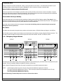
DS7481 Single Phone Line Monitor
Installation Instructions
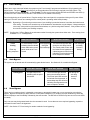
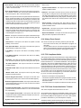
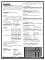
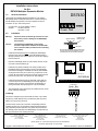
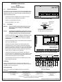
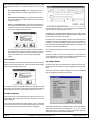
1.0 Description
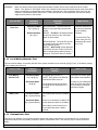
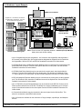
5.0 Programming
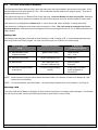
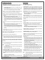
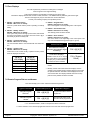
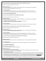
The DS7481 Single Phone Line Monitor is designed for
universal use with most 12 V control/communicators that
accept N/O inputs. It is specifically designed to monitor a
single phone line for fault conditions. When a fault is
detected, the DS7481 automatically closes its N/O relay
contacts to provide a means of signaling the fault.
The zone you connect to at the control panel should be
programmed to provide an alarm sounder output to indicate
the phone line has been lost or cut. For intrusion systems, the
recommended sound is a constant keypad output when
disarmed and the normal alarm sounders when armed.
6.0 Testing
2.0 Specifications
• Power Required: 20 mA @ 12 VDC.
• Phone Fault Output: A N/O dry contact rated 0.5 A @ 12
VDC. Wire to a 24-hour input with a supervised end-of-line
resistor.
• Ringer Equivalence Number: 0.0B
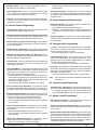
Disconnect the phone line connection. After a 50 second
delay, the line fault output will fault the zone it is wired to.
Verify the proper sounder output.
7.0 Operation
If the DS7481 Monitor detects a phone line fault for more
than 50 seconds, it will activate the relay output.
• Operating Temperature: +32° to +120°F (0° to +49°C)
• Lightning Protection: MOVs and spark gaps provide
protection from lightning surges and static discharges.
• FCC Registration Number: ESVUSA-20057-KX-N
• DOC Certificate Number: 11454
• DOC Certification Number: 1249 5790 A
CAUTION: Handle this circuit board with care. Rough
handling and static discharge can damage this
and other circuits. Ground yourself before
handling any circuit board.
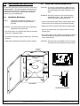
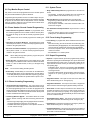
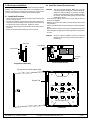
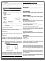
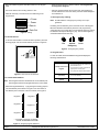
3.0 Installation
Screws are the preferred method of mounting and are
required on U.L. Certificated installations. If mounting to a
DS7080i or a DS7400Xi enclosure, and only one battery is
being used in the system, the preferred mounting position will
be in the lower left corner of the enclosure.
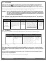
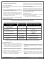
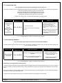
A phone line failure may be caused by:
• A cut or missing phone line, or a mis-wired jack.
To clear a line fault error:
• Determine the cause of the failure and eliminate the cause.
• After eliminating the cause of the failure, wait at least ten
seconds.
• The error will clear if the problem has been eliminated and
the zone output will return to normal.
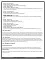
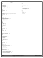
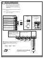
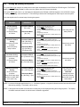
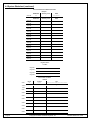
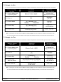
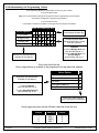
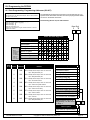
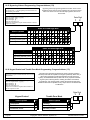
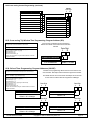
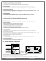
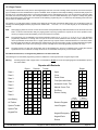
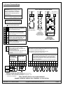
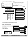
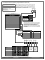
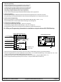
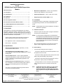
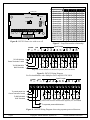
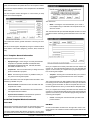
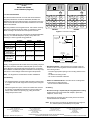
8.0 Wiring to Control Panels
Control Panel
Terminals
Zone Input
_
Aux Power
DS7481
Terminals
EOL
Contacts
Ground
12 VDC Power
+
Line Ring
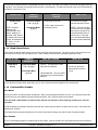
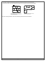
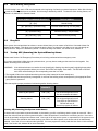
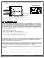
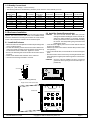
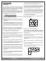
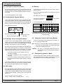
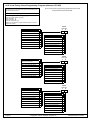
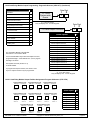
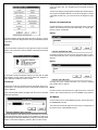
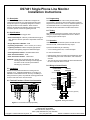
4.0 Terminal Functions / Phone Line Connection
Line Ring
House Ring
House Tip
Control Ring
Control Tip
Line Tip
Line Tip
RJ31X Jack (Optional)
Figure B - Wiring Connections
Figure A - Terminal Functions (supervised)
Detection Systems, Inc.
Fairport, New York 14450
Technical Service: (800) 374-7454
Sales: (800) 289-0096 and (716) 223-4060
Copyright © 1994-95 Detection Systems, Inc.
Fax: (716) 223-9180
DS7481 Installation Instructions P/N 27090C