1
Armed
1
4
Status
2
3
5
6
Power
Fire
®
On
1
2
3
Off
4
5
6
Perimeter
Only
7
8
9
No
Entry
*
0
#
Bypass
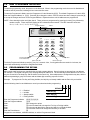
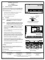
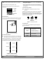
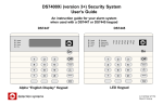
User Guide
for the
DS7060 Control/Communicator
System
Reset
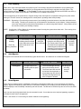
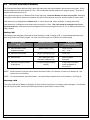
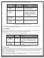
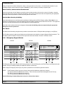
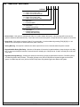
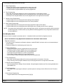
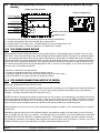
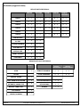
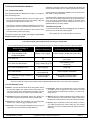
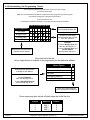
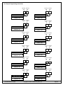
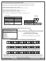
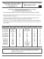
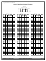
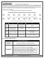
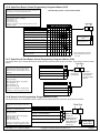
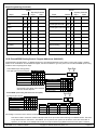
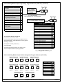
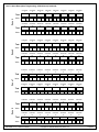
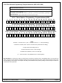
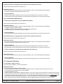
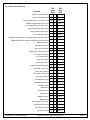
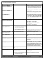
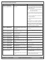
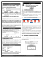
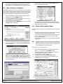
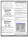
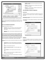
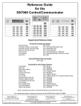
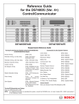
Keypad Quick Reference Guide
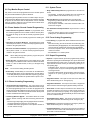
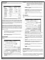
Turning On (arming) your System
Normal Arming
PIN + [On]
Perimeter Arming, no entry delay
PIN + [No Entry] [Perimeter Only]
Perimeter Arming, with entry delay
PIN + [Perimeter Only]
Maximum Security Arming
PIN + [No Entry] [On]
Force Arming
PIN + Arming Sequence + [Bypass]
Zone Bypass
PIN + [Bypass] followed by
the Zone number
Quick Arm
[#] + [On]
Turning Off (disarming) your System
PIN + [Off]
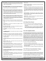
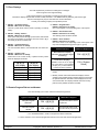
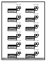
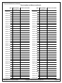
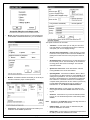
Commands for other System Features
Chime Mode
PIN + [#] [7]
Zone Test
PIN + [#] [8] [1]
Read Alarm History
PIN + [#] [8] [9]
Battery Test
PIN + [System Reset]
Communicator Test
PIN + [#] [8] [2]
Fire Reset
PIN + [System Reset]
Fire Trouble
PIN + [Off] to silence
PIN + [System Reset] to clear
Remote Program Dial Out
PIN + [#] [8] [3]
Remote Program Answer
PIN + [#] [8] [6]
Local Battery/Sounder Test
PIN + [#] [8] [5]
Error Display
PIN + [#] [8] [7]
Error Display Reset
PIN + [System Reset]
Clear Zone Bypass
PIN + [Bypass] [*] to clear
Guest Code Enable
PIN + [#] [8] [4]
NOTE: Examples are shown in Commercial Mode but are valid for any mode.
Detection Systems PTY Ltd.
Unit 21, 45 Gilby Road
Mount Waverley, Victoria 3149, Australia
61 3 9558 8088
Fax: 61 3 9558 8089
Copyright © 1996 Detection Systems, Inc.
Detection Systems PTY Ltd.
Unit 2, The Riverside Centre
148 James Ruse Drive
Parramatta, NSW 2150, Australia
61 2 891 4944
Fax: 61 2 891 5844
Detection Systems Ltd.
19, Rue du 19 Mars-78130
Les Mureaux, France
Phone/Fax: 33 1 34 74 9576
Detection Systems, Inc., 130 Perinton Parkway, Fairport, New York, USA 14450-9199
(716) 223-4060 • (800) 289-0096 • Fax: (716) 223-9180
Detection Systems Ltd.
Unit 13-18, 17/F New Commerce Centre
19 On Sum Street, Shatin, N.T.
Hong Kong
852 2635 2815
Fax: 852 2648 7986
DS7060 User Guide P/N 29955 B
TABLE OF CONTENTS
1.0 OPERATING GUIDE ........................................................................................................................................................... 3
1.1
1.2
Understanding the DS7443, DS7445, and DS7447 Keypads ................................................................................. 3
Personal Identification Numbers .............................................................................................................................. 4
Adding a PIN ........................................................................................................................................................................ 4
Removing a PIN ................................................................................................................................................................... 4
1.3
1.4
1.5
1.6
Turning ON (arming) the System .............................................................................................................................5
Quick Arming the System ........................................................................................................................................6
Easy Exit .................................................................................................................................................................. 6
Turning OFF (disarming) the System/Silencing Alarms ........................................................................................... 6
1.7
1.8
1.9
1.10
1.11
1.12
1.13
1.14
1.15
Force Arming ........................................................................................................................................................... 7
Auto Bypass ............................................................................................................................................................ 7
Zone Bypass ............................................................................................................................................................ 7
Chime Mode ............................................................................................................................................................ 8
Zone Test .................................................................................................................................................................8
Local Battery/Sounder Test ......................................................................................................................................9
Communicator Test .................................................................................................................................................. 9
Read Alarm History ................................................................................................................................................ 10
Fire Reset/Fire Trouble .......................................................................................................................................... 10
Turning Off (disarming) the System under Duress ............................................................................................................... 6
Fire Reset ........................................................................................................................................................................... 10
Fire Trouble ........................................................................................................................................................................ 10
1.16
Remote Program Dial-out and Answer .................................................................................................................. 11
Call for Remote Programming ............................................................................................................................................ 11
Answer for Remote Programming ...................................................................................................................................... 11
1.17
1.18
1.19
1.20
Error Displays ........................................................................................................................................................ 11
Duress Code .......................................................................................................................................................... 12
Guest Code............................................................................................................................................................ 12
Emergency Procedures ......................................................................................................................................... 12
Identifying Alarm Sounds ................................................................................................................................................... 12
Silencing Alarms ................................................................................................................................................................. 12
A Cautionary Note .............................................................................................................................................................. 13
Above All Else, Common Sense Should Prevail ................................................................................................................ 13
Caution When Entering A Building ..................................................................................................................................... 13
Fire Alarms ......................................................................................................................................................................... 13
1.21
1.22
Emergency Keypad Alarms ................................................................................................................................... 13
Fire Safety ............................................................................................................................................................. 14
If Installed in Family Residences ........................................................................................................................................ 14
Having and Practicing an Escape Plan .............................................................................................................................. 14
Installation Considerations ................................................................................................................................................. 14
Index ......................................................................................................................................................................................... 16
Page 2
Copyright © 1996 Detection Systems, Inc.
DS7060 User Guide
1.0
OPERATING GUIDE
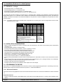
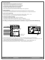
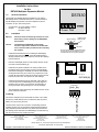
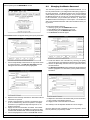
1.1
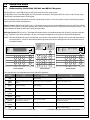
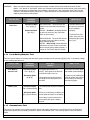
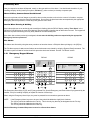
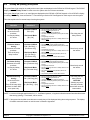
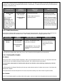
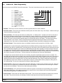
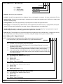
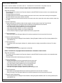
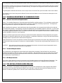
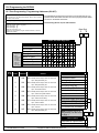
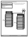
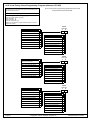
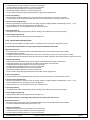
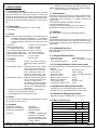
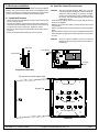
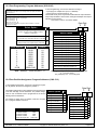
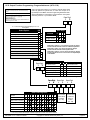
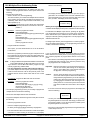
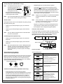
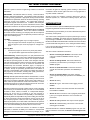
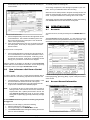
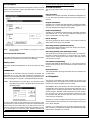
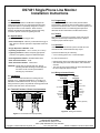
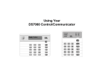
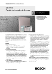
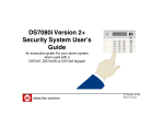
Understanding the DS7443, DS7445, and DS7447 Keypads
The DS7443 is a 6 zone LED keypad; its LEDs represent the zones of the system.
The DS7445 is an 8 zone LED keypad; its LEDs represent the zones of the system (LEDs for zones 7 and 8 are not used).
The DS7447 is an alpha-numeric LCD keypad.
All three keypads display information on various control panel functions. A built-in sounder is used to annunciate keystroke
entries and as an interior warning device.
Volume Control (DS7445 and DS7447 only): The keypad sounder volume can be adjusted using the [1] and [4] keys along
with the [*] key. Hold the [*] key while pressing the [1] key to increase the volume or the [4] key to decrease the volume. The
volume adjustment does not affect the volume during an alarm.
Backlight Control (DS7447 only): The display backlight intensity can be adjusted using the [3] and [6] keys along with the
[*] key. Hold the [*] key while pressing the [3] key to increase the brightness or the [6] key to decrease the brightness.
NOTE: After the backlight and volume are adjusted, you must arm, then disarm the system once to store this information in
the control panel. If power is disconnected before the panel is armed, the backlight and volume levels will return to
the default settings.
Armed
1
4
Status
2
3
5
6
Power
Fire
Armed
®
Status
®
Power
Fire
2
3
Off
Perimeter
Only
4
5
6
7
8
9
No
Entry
*
0
#
Bypass
Perimeter
Status
Supervisory
Power
Bell Silenced
Fire
Trouble
1 2 3 4 5 6 7 8
On
On
1
Armed
1
2
3
Off
4
5
6
Perimeter
Only
7
8
9
No
Entry
*
0
#
Bypass
On
1
2
3
Off
4
5
6
Perimeter
Only
7
8
9
No
Entry
*
0
#
Bypass
System
Reset
System
Reset
DS7447 KEYPAD
®
System
Reset
DS7443 KEYPAD
DS7445 KEYPAD
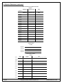
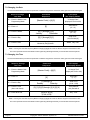
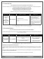
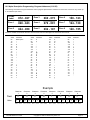
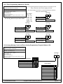
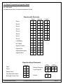
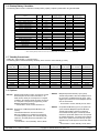
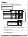
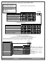
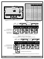
This chart will help you understand what each Light/LED represents.
LIGHT
OFF
Armed
(red)
The control panel is disarmed.
An exit delay is in progress or an alarm
has occurred.
The control panel is armed and no alarms have
occurred.
Status
(green)
One or more zones are not ready
to arm.
One or more zones are bypassed.
All zones are ready to arm.
Power
(green)
The control panel has lost power.
No AC or battery.
Control panel problems. See Section 5.17,
Error Displays.
Normal operation.
There are no fire alarms.
A fire zone is in alarm.
A fire trouble condition exists.
The perimeter is not armed.
This light will not flash.
The perimeter is armed.
Supervisory*
(yellow)
This light will not be used by the
DS7060.
Not used.
Not used.
Bell Silenced*
(yellow)
The bells do not need to be or
have not been silenced.
This light will not flash.
The bells have been silenced. To clear, enter the
Fire Reset command.
There are no trouble conditions.
This light will not flash.
A trouble condition exists.
There are no zone alarms.
A zone (1-6) is in alarm.
A zone (1-6) is not ready to arm or if a fire zone, a
trouble condition exists.
Fire
(red)
Perimeter*
(yellow)
Trouble*
(yellow)
Zone LEDs**
(red)
FLASHING
* = This light is present on the DS7445 only.
DS7060 User Guide
ON
** = This light is present on the DS7443 and DS7445.
Copyright © 1996 Detection Systems, Inc.
Page 3
1.2
Personal Identification Numbers
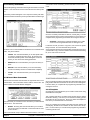
The Personal Identification Number (PIN) is the 4-digit code users enter at the keypad to gain access to the system. A PIN
may be assigned to each User Number 001-015. The User Number identifies each person using the system. There are 15
possible User Numbers (001-015).
Your system may have up to 15 different PINs, each 4 digits long. Each User Number can have only one PIN. Attempting
to assign the same PIN to multiple User Numbers will result in the three-beep error tone, and the change will not be made.
User Number 001 is designated as a Master Code. It can be used to add, delete, read back, or change other PINs.
User Number 001 is shipped from the factory with the sequence of 1234. This code should be changed to one of your
personal preference. PINs should never be programmed with common sequences such as 1111 or 2468 because they are
easily violated.
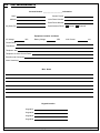
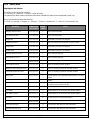
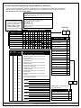
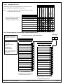
Adding a PIN
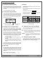
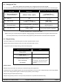
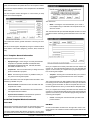
The following chart will guide you through the steps necessary to add or change a PIN. It is recommended that this procedure be performed at a DS7447 keypad. No visual cues will be given from a DS7443 or DS7445 keypad.
STEPS TO CHANGE
A PIN
COMMAND SEQUENCE
IF ACCEPTED,
THE DISPLAY READS
#1 Enter the Master Code
Programming Mode
[Master Code] + [#] [0]
#2 Enter the User Number
[0] [0] [1] through [0] [1] [5]
"Enter PIN"
#3 Enter the PIN
Any 4 digits (Each user
must have a different PIN).
Enter PIN Again
End with #
#4 Enter the PIN again followed
by the [#] key.
PIN (same 4 digits as above)
then [#]
"Enter User No."
(001 . . 015)
A long beep will sound to
signify acceptance of
the new PIN.
NOTE: Users 014 and 015 may be used for Duress and Guest Codes. See Sections 5.18 and 5.19, Address 09 - User
Control for more information.
NOTE: You cannot read back User PIN numbers. You should keep a separate list for future reference. See Page 22.
Removing a PIN
To remove a PIN enter a [Master Code] [#] [0], the User Number of the PIN to be canceled, and then [#] again. User Number
001 can not be canceled. See Section 8.9 for special uses for User Number 14 and 15 PINs.
Page 4
Copyright © 1996 Detection Systems, Inc.
DS7060 User Guide
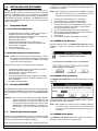
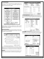
1.3
Turning ON (arming) the System
The green Status light must be on steady and no zone lights are displayed on the DS7443 or DS7445 keypad. The DS7447
display must read “Ready To Arm” in order to arm the system with one of these commands.
If the green Status light is not on, or zone lights are displayed on the DS7443 or DS7445 keypad, or if the DS7447's display
is reading “Not Ready,” then see Section 5.7 Force Arming or Section 5.9 Zone Bypass for other ways to arm the system.
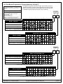
This chart explains the five normal ways of arming the system.
TYPE OF ARMING
DESIRED
COMMAND
SEQUENCE
Normal Arming
No one left on the
premises.
An entry/exit delay
is in effect.
Commercial Mode
PIN + [On]
Perimeter Instant
Arming
Someone still on the
premises.
There is NO entry
delay in effect.
Commercial Mode
PIN + [No Entry] +
[Perimeter Only]
Perimeter Arming
Someone still on the
premises.
An entry/exit delay
is in effect.
Commercial Mode
PIN + [Perimeter Only]
Maximum Security
Arming
No one left on the
premises.
There is NO entry delay
in effect. An alarm WILL
occur upon entry.
Commercial Mode
PIN + [No Entry] [On]
Residential Mode
[#] + [On]
Residential Mode
[#] + [No Entry] +
[Perimeter Only]
Residential Mode
[#] + [Perimeter Only]
Residential Mode
[#] + [No Entry] + [On]
WHAT WILL HAPPEN
•
•
•
•
WHAT TO DO
The red Armed Light will begin to flash.
The green Status light will turn off.
“Armed” will be displayed (DS7447).
“Exit Now” will display (DS7447) during the exit delay
interval.
• A single beep will sound.
• The red Armed light will turn on steady after the exit
delay interval.
Exit during the exit
delay interval.
• The red Armed Light will begin to flash.
• “Perimeter Inst.” will be displayed (DS7447).
• “Exit Now” will display (DS7447) during the exit delay
interval.
• A single beep will sound.
• The red Armed light will turn on steady after the exit
delay interval.
• The yellow Perimeter light (DS7445) will turn on
steady.
• Only exterior protection zones will be armed.
Move freely around
the interior.
• The red Armed Light will begin to flash.
• “Perimeter On” will be displayed (DS7447).
• “Exit Now” will display (DS7447) during the exit delay
interval.
• A single beep will sound.
• The red Armed light will turn on steady after the exit
delay interval.
• The yellow Perimeter light (DS7445) will turn on
steady.
• Only exterior protection zones will be armed.
Move freely around
the interior.
•
•
•
•
The red Armed Light will begin to flash.
The green Status light will turn off.
“Armed Instant” will be displayed (DS7447).
“Exit Now” will display (DS7447) during the exit delay
interval.
• A single beep will sound.
• The red Armed light will turn on steady after the exit
delay interval.
Exit during the exit
delay interval.
CAUTION:
Violating any zone
after the exit delay
interval will cause an
instant alarm.
NOTE: In commercial burglar applications for U. L. Certificated systems, a ring-back indication and bell test should be heard
after arming (closing). If not heard, call for service.
NOTE: If the system has invisible zones that are not ready, they will be displayed during the arming sequence. The display
of invisible zones will remain on until the zone is cleared or bypassed.
DS7060 User Guide
Copyright © 1996 Detection Systems, Inc.
Page 5
1.4
Quick Arming the System
If Quick Arming is not used, a PIN must be entered at the beginning of all arming command sequences. When Quick Arming
is used, the following shortcuts are available. Quick Arming is disabled by default. To select the Quick Arming feature, see
Section 8.10, Address 10 - General Control.
QUICK ARMING COMMAND SEQUENCE
TYPE OF ARMING
[#] + [On]
Normal Arming
[#] + [No Entry] + [Perimeter Only]
1.5
Perimeter Instant Arming - no entry delay
[#] + [Perimeter Only]
Perimeter Arming - entry/exit delay
[#] + [No Entry] + [On]
Maximum Security Arming
Easy Exit
If the system is armed and there have been no zones violated, then you can reenter a Quick Arm Command without first
disarming the system. This allows you to change the arming level or to restart the exit delay so you can exit through an
entry/exit zone. Easy Exit is disabled by default. To select the Easy Exit feature, see Section 8.10, Address 10.
1.6
Turning OFF (disarming) the System/Silencing Alarms
Please read Section 5.20 Emergency Procedures prior to being confronted with an emergency event.
If you have entered the building through a perimeter door, you may hear a steady pre-alert tone from the keypads. If so,
disarm according to the chart below.
WARNING: If the bells and sirens are on and/or the red Armed light is flashing, then the keypad is signaling that an alarm
has occurred sometime before your arrival. The DS7447 will display “Zone Alarm.” The DS7443 or DS7445
zone LEDs will be flashing for the corresponding zone that is in alarm.
• The keypad will also issue a pulsed tone during the entry delay instead of the usual steady tone.
• If the alarm has not been previously investigated, do not enter the building unless accompanied by the appropriate Emergency Services’ personnel.
This chart explains proper procedures for disarming and/or silencing alarms.
TYPE OF DISARMING
COMMAND
SEQUENCE
WHAT WILL HAPPEN
Disarming the System
PIN + [Off]
The red Armed light will turn off.
Pre-alert sounders will silence.
Silencing Alarms
PIN + [Off]
The red Armed light will turn off.
Zone LEDs on the DS7443 or
DS7445 will turn off.
Alarms in progress will silence.
Turning Off (disarming) the System under Duress
A duress code is used when someone demands, by threatening your life or well-being, that the system be turned off. When
used, the code will both turn off the system and report a silent duress alarm if connected to a monitoring service. User code
14 can be optionally configured as a duress code. User code 14 will not arm the system, or report duress, if the system is not
armed. Extreme care should be used when entering your PIN to turn off the system, so a duress code is not inadvertently
entered. User Code 14 is not a duress code by default. You must program the control panel that User Code 14 is the duress
code. See Section 8.9, Address 09 for more information.
Page 6
Copyright © 1996 Detection Systems, Inc.
DS7060 User Guide
1.7
Force Arming
When one or more zones are faulted, the system may be Force Armed (if programmed at Address 10) by bypassing the
faulted zones. The green Status light will be off on all keypads when Force Arming is required to arm the system. The
DS7447 display will read “Not Ready” or “Fire Trouble” (if a fire zone is open) and the DS7443 and DS7445 zone LEDs (16) will be on if one of those zones is faulted. See Section 8.10 to enable Force Arming.
Force Arming during an AC power failure: Regular arming of the control panel is not permitted during an AC power failure.
Having to Force Arm serves as a warning that the control panel is operating under backup battery.
WARNING: Bypassing or Force Arming removes some of your building's protection because it excludes the faulted zones
from arming. Therefore, an intrusion may not be detected or the detection may be delayed. Always attempt to
correct any zone problems (close doors and windows, etc.) before using these features. If the problem can not
be corrected, contact your installing company.
NOTE: See Section 5.9 Zone Bypass for an alternate method of arming the system when faults exist. Force arming is not
available in U. L. Listed systems.
TYPE OF ARMING
WHAT WILL HAPPEN
Force
Arming
• A 5 second beep occurs,
indicating there are faulted
zones and that the control
Enter any
panel needs to be Force
arming sequence.
Armed.
1.8
WHAT TO DO
WHAT WILL HAPPEN
WHAT TO DO
Press [Bypass] • The red Armed light will flash
during the
during the exit delay interval.
5 second beep. • The control panel will arm with
the faulted zones bypassed, or
a three-beep error tone will occur
indicating Force Arming has not
been accepted or allowed.
Exit during the
exit delay
interval if
leaving.
Auto Bypass
The system can be armed and will automatically bypass faulted zones. See Section 8.10 to enable Auto Bypass.
1.9
TYPE OF ARMING
WHAT WILL HAPPEN
Auto Bypass
• A single beep occurs,
indicating that the panel
has armed.
WHAT WILL HAPPEN
• The red Armed light will flash
during the exit delay interval.
• The control panel will arm with
the faulted zones bypassed, or
a three-beep error tone will occur
indicating Auto Bypass has not
been accepted or allowed.
WHAT TO DO
Exit during the
exit delay
interval if
leaving.
Zone Bypass
There may be occasions when it is desirable or necessary to temporarily bypass one or more zones prior to arming the
system. Bypass commands only work when the control panel is disarmed. For instance, an open window may cause the
DS7447 display to read "Not Ready" followed by the zone number. The DS7443 or DS7445 may have one of its zone LEDs
on steady.
Only one zone may be bypassed each time the command is used. If more than one zone requires bypassing, repeat the
command for each zone to be bypassed.
NOTE: See Section 5.7 Force Arming for another method of zone bypassing.
DS7060 User Guide
Copyright © 1996 Detection Systems, Inc.
Page 7
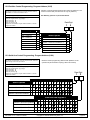
This chart explains the procedure for bypassing a faulted zone prior to arming the system.
TYPE OF BYPASSING
DESIRED
Bypass Faulted
Zones
Read Bypassed
Zones
Clear Individual
Bypassed Zone(s)
COMMAND
SEQUENCE*
PIN + [Bypass] [Zone #] • The Status light will begin to flash if no
other zones are violated.
PIN + [Bypass]
• Bypass will be displayed (DS7447)
followed by the zone number of any
bypassed zones. The DS7443 or
DS7445 will flash the zone LED of the
zone being bypassed.
PIN + [Bypass] [Zone #] • Individual zone bypasses will be cleared.
PIN + [Bypass] [*]
Clear all
Bypasses
WHAT WILL
HAPPEN
• All bypasses will be cleared.
* If in “Residential Mode” substitute the [#] key for the PIN.
NOTE: All bypasses are cleared when the system is disarmed, unless they are on 24-hour zones. To clear a bypass on a
24-hour zone, use Clear Individual or Clear All.
1.10 Chime Mode
Chime Mode causes the keypad sounders to beep each time a Perimeter or Entry/Exit zone is violated while the control
panel is off (disarmed). The [#] [7] command is used to both turn Chime Mode off and on.
This chart explains the procedure for turning ON and turning OFF Chime Mode.
ACTION DESIRED
COMMAND
SEQUENCE*
WHAT WILL HAPPEN
Turn ON
Chime Mode
PIN + [#] [7]
• The keypad sounders will beep for 2 seconds each
time a perimeter or entry/exit zone is violated. The
DS7447 display will read “Chime Mode On” for 5
seconds.
Turn OFF
Chime Mode
PIN + [#] [7]
• The DS7447 display will read “Chime Mode Off” for
5 seconds.
* If in “Residential Mode” substitute the [#] key for the PIN.
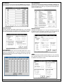
1.11 Zone Test
The Zone Test is used to confirm that detectors will report alarms. Zone Test works on all zones, except 24-hour zones and
fire zones. While the keypad is in Zone Test, no control panel alarms will activate an alarm, except 24-hour zone alarms and
fire alarms. These will override the Zone Test function. Caution: Be sure not to activate 24 hour or fire zones during the
zone test or an alarm signal will be sent.
The Zone Test will initiate communicator reports only if both “System in Test Report” and “System in Test Restoral Report” are
programmed. See Section 8.30, Address 36 - Test Reports, System Test.
Page 8
Copyright © 1996 Detection Systems, Inc.
DS7060 User Guide
WARNING:
Make sure that the report value programmed at these locations will be clearly understood at the Central
Station. The “System in Test Report” will be sent, followed by the alarm and restoral reports of the zones being
tested, providing their corresponding report address is programmed. After completion of the Zone Test, the
“System in Test Restoral Report” will be sent. If these two reports are misunderstood, then the zone alarms
might be perceived as a real violation.
TYPE OF TEST
Zone Test
COMMAND
SEQUENCE
WHAT WILL
HAPPEN
WHAT TO DO
Commercial Mode
PIN + [#] [8] [1]
DS7443/DS7445: The zone LEDs will
flash for any zones that have not been
tested.
DS7447: “Test Zone” will display followed
by the zone number of any zones that
have not been tested.
Test each detector one
at a time as instructed
by the installing
company.
Residential Mode
[#] + [8] [1]
DS7443/DS7445: The zone LED will turn
on steady for the zone that is currently
being violated (tested).
DS7447: “Now Testing” will be displayed
followed by the zone number of the zone
that is currently being voilated (tested). It
returns to “Test Zone” after the violation.
To exit the Zone Test
mode, enter your PIN
followed by [#] or press
the [*] key.
1.12 Local Battery/Sounder Test
This test uses the battery to manually activate all the system sounders for two seconds, [#] [8] [5] only. If the battery voltage
is low, a battery fault will occur.
TYPE OF TEST
Local Battery/
Sounder Test
COMMAND
SEQUENCE
WHAT WILL
HAPPEN
WHAT TO DO
Commercial Mode
PIN + [#] [8] [5]
• All keypad lights will turn on.
NOTE: Zone lights on the DS7443
and DS7445 will not turn on.
If test fails, the control panel
will indicate a control problem.
Residential Mode
[#] [8] [5]
Battery Test
• The keypad sounder and all alarm
sounding devices will operate for 2
seconds.
Commercial Mode
PIN + [System Reset]
• The control panel will perform a battery
test.
Residential Mode
[#] + [System Reset]
• If there is a Low Battery condition, the
control panel will report a Low Battery.
If power in your building has
been off recently, wait 2 hours
for the battery to recharge
and then try again.
• If the battery is now functional, the
control panel will report a battery
restoral.
1.13 Communicator Test
This test is only available if your system transmits alarms and system information to a monitoring service, and has been
programmed by the security installing company to permit communicator tests. This test may only be used in the disarm
mode.
DS7060 User Guide
Copyright © 1996 Detection Systems, Inc.
Page 9
A long beep will initially sound to acknowledge the start of the test. If the test is successful, the sounder will again issue one
long beep. If the test fails, the keypad sounder will turn on continuously. To silence the sounder, enter your PIN followed by
the [#] key or press the [*] key.
TYPE OF TEST
COMMAND
SEQUENCE
Communicator
Test
Commercial Mode
PIN + [#] [8] [2]
NOTE: Requires
Addresses 36
“Communicator Test
Report,” Address 37
“Account Code” (Phone
#1), Address 38 “Phone 1
Format” and Address 4041 “Phone 1” to be
programmed.
Residential Mode
[#] [8] [2]
WHAT WILL
HAPPEN
• A long beep will sound.
• A “Test” report is sent to the
monitoring service.
WHAT TO DO
If test fails, the keypad
sounder will beep 3 times.
NOTE: This test may take
several minutes to complete
because the control will try
several attempts before it
fails this test. A retry will
occur 30 minutes after failure,
and then 24 hours thereafter.
1.14 Read Alarm History
This feature will display which zones were in alarm during the last armed period. The alarm memory will remain from one
armed cycle to the next if no new alarms occur. Alarm memory will clear when entering programmers mode.
TYPE OF TEST
COMMAND
SEQUENCE
Read Alarm
History
Commercial Mode
PIN + [#] [8] [9]
Residential Mode
[#] [8] [9]
WHAT WILL HAPPEN
DS7447: The last alarm to take
place will be displayed.
WHAT TO DO
To exit from the Alarm
History Mode, press the
[*] key.
DS7443/DS7445: The zone LEDs
will flash for any zones that have
alarmed.
To exit the Alarm History Mode, press the [*] key or wait 5 seconds and the keypad will exit automatically.
1.15 Fire Reset/Fire Trouble
Fire Reset
During a fire alarm, exit the premises immediately. When you have determined there is no fire, you may silence the bells/
sirens before you can initiate the [System Reset] command. PIN + [Off] will silence the sounders.
This will allow a determination of which smoke detector has alarmed so the monitoring company may verify its
operation.
A PIN followed by the [System Reset] key will reset any smoke detectors after a fire alarm has occurred. See Section 8.8,
Address 08 - Outputs.
The System Reset command will perform a fire reset, will perform a battery test, and will clear all system troubles.
Fire Trouble
A Fire Trouble display signifies a problem with the fire system, such as a break in the wiring that monitors smoke detectors.
Page 10
Copyright © 1996 Detection Systems, Inc.
DS7060 User Guide
A Fire Trouble will be indicated by a short beep from the keypad sounders every 10 seconds. The DS7447 will display “Fire
Trouble” followed by the zones in a trouble condition. The DS7443 will turn the Fire light on steady and will light the corresponding zone LEDs. The DS7445 will turn the Fire and Trouble lights on steady and will light the corresponding zone LEDs.
Notify your installing company immediately if the Fire Trouble message is displayed.
The Fire Trouble beep can be silenced with any PIN followed by the [Off] key. After problems have been remedied, a PIN
followed by [System Reset] should be entered to clear the “Fire Trouble” display.
1.16 Remote Program Dial-out and Answer
Call for Remote Programming
This command can only be entered when the control is disarmed. Phone numbers 1 and 3 must be programmed, along with
account code 1. The panel will call phone number 3 and attempt to connect for downloading. While programming is underway the Status, Armed, and Power LEDs will flash. If the panel is already using the phone line, it will sound the three beep
error tone.
Answer for Remote Programming
The panel will automatically pick up the phone line to answer a remote programming call. While programming is underway
the Status, Armed, and Power LEDs will flash. If the panel is already using the phone line for a report communication, it will
sound the three beep error tone. This command can only be entered when the control is disarmed.
This chart will help you to call or answer the Remote Programmer.
TYPE OF FUNCTION
COMMAND SEQUENCE
WHAT WILL HAPPEN
Remote Program
Dial-out**
Commercial Mode
PIN + [#] [8] [3]
Residential Mode
[#] [8] [3]
The panel will call the remote
programmer.
Remote Program
Answer
Commercial Mode
PIN + [#] [8] [6]
Residential Mode
[#] [8] [6]
The panel will answer a call
from the remote programmer.
** = Phone numbers 1 and 3 must be programmed. Phone #1 Account Code must be programmed.
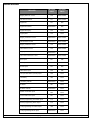
1.17 Error Displays
Control panel problems are indicated by a flashing green Power light. The DS7447 display will also read “Control Trouble,
Enter [#] [8] [7].” The DS7443 and DS7445 will only flash the green Power light. The error messages may only be read when
the control is disarmed. Contact your installing company if the problems persist.
ACTION DESIRED
ACTION DESIRED
Read the Error Display when the Green
Power light is flashing.
Commercial Mode
PIN + [#] [8] [7]
Residential Mode
[#] [8] [7]
Clear Error Display **
Caution: Clear the error display only on the
advice of your installing company or if you are
certain the problem has been remedied.
Commercial Mode
PIN + [System Reset]
Residential Mode
PIN + [System Reset]
** = Battery Trouble and Communicator Err displays must be cleared by the [System Reset] command sequence even
after the problem has been remedied. These displays will not self clear. All the other error displays will self clear from
the keypads once the problem has been remedied.
DS7060 User Guide
Copyright © 1996 Detection Systems, Inc.
Page 11
1. DS7447 - “AC Power Failure”
DS7443 or DS7445 - LED 1 turns on steady
There is a power failure and the panel is operating on backup battery.
2. DS7447 - “Battery Trouble”
DS7443 or DS7445 - LED 2 turns on steady
If the system has just been through a power failure, wait at least two hours for the battery to recharge, then enter a PIN +
[System Reset] to perform a battery test.
3. DS7447 - “Communicator Err”
DS7443 or DS7445 - LED 3 turns on steady
The communicator failed to communicate with the central station.
4. DS7447 - “System Fault”
DS7443 or DS7445 - LED 4 turns on steady
Internal error in the control circuitry or optional circuitry. These system faults are: Ram Fault, ROM Fault, EEPROM
Fault.
5. DS7447 - “Keypad Fault”
DS7443 or DS7445 - LED 5 turns on steady
One of the keypads is not responding to the control panel.
6. DS7447 - “Alarm Fuse Fault”
DS7443 or DS7445 - LED 6 turns on steady
The auxiliary power has been shorted.
7. DS7447 - “Zone Trouble”
DS7443 or DS7445 - LED of the zone in trouble will light
One of the zones is not responding to the control panel. This may also be displayed during power-up (if so, ignore).
1.18 Duress Code
User Code 14 may be used as a duress PIN number. When the system is disarmed using this duress code, a silent report is
sent to the central station. Duress codes are intended to be used when a user is forced to disarm the system. There are two
program addresses that must be programmed to activate this feature. Program Address 09 - User Control, to duress code
digit = 1. Program Address 31 - Open/Close Duress Report, to a value that is understood as duress by the central station.
1.19 Guest Code
User Code 15 may be programmed to be a Guest Code. After the Guest Code has been programmed, it is enabled by
depressing [PIN] + [#] [8] [4]. The Guest Code may now be used to arm and disarm the system. It remains active until the
panel is disarmed with any other valid code. Refer to Section 8.9, Address 09 to activate the Guest Code option. If PIN 15 is
used as a guest code, remember to change PIN 15 according to Section 5.2.
1.20 Emergency Procedures
Identifying Alarm Sounds
Your alarm system may be programmed for a steady alarm sound or a pulsed alarm sound. It is important to learn the
difference between a fire alarm sound and an intrusion alarm sound before you are confronted with an actual emergency.
Silencing Alarms
All alarms can be silenced with any PIN that has disarm privileges. Entering your PIN + [Off] will silence the alarm and turn
off (disarm) the control.
Page 12
Copyright © 1996 Detection Systems, Inc.
DS7060 User Guide
A Cautionary Note
How you respond to an alarm will depend, mostly, on the type and time of the alarm. You should seek the advice of your
installing company as they install your system, not later (e.g. after an alarm) to develop a response plan.
Above All Else, Common Sense Should Prevail
If there is any threat or hint of danger to yourself or others on the premises, such as in the event of a fire alarm, everyone
should be instructed to leave the premises immediately. Do not enter the premises unless accompanied by the appropriate
Emergency Services’ personnel, or after they have given the OK to enter.
Caution When Entering A Building
If the bells and sirens are on and/or the red Armed light is flashing (with the DS7447 display reading “Zone Alarm” or the
DS7443 or DS7445 having its zone LEDs flashing) then the keypad is signaling that an alarm has occurred. The keypad will
also issue a pulsed tone during the entry delay instead of the usual steady tone.
If the alarm has not been previously investigated, do not enter the building unless accompanied by the appropriate
Emergency Services’ personnel.
Fire Alarms
Fire Alarms are silenced by using the same procedure as intrusion alarms: a PIN (with disarm privileges) + the [Off] key.
The Fire Alarm system is not reset until alarms at smoke detectors are cleared by using the [System Reset] command. The
Fire Alarm system will not be functional until this procedure has been followed. See the “Fire Reset” section.
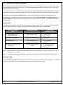
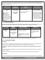
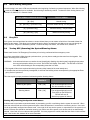
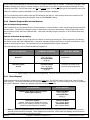
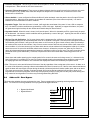
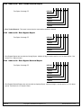
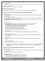
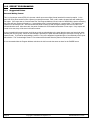
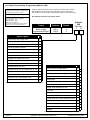
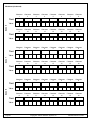
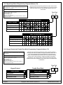
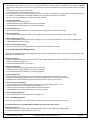
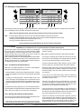
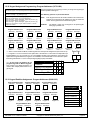
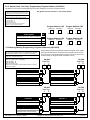
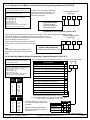
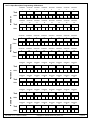
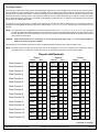
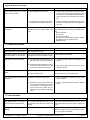
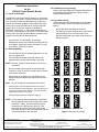
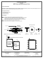
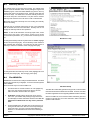
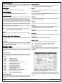
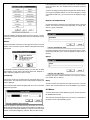
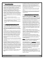
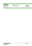
1.21 Emergency Keypad Alarms
DS7447
DS7443
Armed
1
4
Status
2
3
5
6
Power
Fire
Armed
DS7445
®
Status
®
Power
Fire
4
2
5
3
Off
6
Perimeter
Only
7
8
9
No
Entry
*
0
#
Bypass
1
2
3
Off
4
5
6
Perimeter
Only
7
8
9
No
Entry
*
0
#
Bypass
B
Help
C
Supervisory
Power
Bell Silenced
Fire
Trouble
1 2 3 4 5 6 7 8
A
B
C
Help
®
On
1
2
3
Off
4
5
6
Perimeter
Only
7
8
9
No
Entry
*
0
#
Bypass
System
Reset
System
Reset
A
Perimeter
Status
On
On
1
Armed
System
Reset
A
B
C
Help
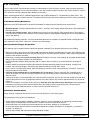
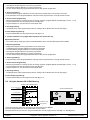
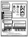
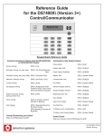
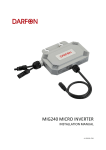
The Emergency Alarm Keys [A], [B], and [C] may generate Fire, Special Emergency, and Panic Alarms if programmed by the
installer. Ask your installing company to explain the function of these keys.
When using the Emergency Alarm Keys, they must be pressed for two seconds to generate an alarm.
NOTE:
If the Emergency Alarm keys are to be used, they should be labeled to signify their functions.
The “A” key should be labeled as the Fire key. This is the only key that may be designated as the Fire key.
The “B” key should be labeled as the Help key.
The “C” key should be labeled as the Panic key.
Use the Disarming Command Sequence to cancel or silence these alarms.
DS7060 User Guide
Copyright © 1996 Detection Systems, Inc.
Page 13
1.22 Fire Safety
This fire alarm system can provide early warning of a developing fire. Such a system, however, does not ensure protection
against property damage or loss of life resulting from a fire. Any fire alarm system may fail to warn for any number of reasons
(e.g. smoke not reaching a detector that is behind a closed door).
When considering detectors for residential applications, refer to NFPA Standard 72, “The National Fire Alarm Code.” This
standard is available at a nominal cost from: The National Fire Protection Association, Batterymarch Park, Quincy, MA 02269.
If Installed in Family Residences
Adherence to the NFPA Standard 72 can lead to reasonable fire safety when the following items are practiced:
• Minimize hazards: Avoid the three traditional fire killers: smoking in bed, leaving children home alone, and cleaning with
flammable liquids.
• Provide a fire warning system: Most fire deaths occur in the home, the majority, during sleeping hours. The minimum
level of protection requires smoke detectors to be installed outside of each separate sleeping area and on each additional
story of the dwelling.
For added early warning protection, it is recommended that detectors be installed in all separated areas including the basement, bedrooms, dining room, utility room, furnace room, and hallways.
Having and Practicing an Escape Plan
A fire warning may be wasted unless the family has planned in advance for a rapid and safe exit from the building.
• Draw a floor plan of the entire house showing two exits from each bedroom and two from the house. Since stairwells and
hallways may be blocked during a fire, the plan should provide exits from bedroom windows. Make copies of the plan and
practice it with all family members.
• Prearrange a meeting place outside and away from the residence. Once out of the building, all occupants should immediately go to the pre-selected location to be accounted for.
• Provide a barricade between family members and fire, smoke, and toxic gases (e.g. close all bedroom doors before
retiring).
• Children should be instructed on opening their bedroom windows and exiting safely from the building. If exiting is not
possible, they should be taught to stay at the open window and shout for help until it arrives.
• In the event of a fire alarm after retiring, wake the children by shouting to them from behind your closed door. Tell them to
keep their bedroom doors closed.
• If the top of your bedroom door is uncomfortably hot, do not open it. There is most likely fire, intolerable heat, or
smoke on the other side. Shout to all family members to keep their bedroom doors closed and to exit the building via
alternate routes.
• If the top of the door is not uncomfortably hot, brace the bottom of the door with your foot, and the top with one hand, then
open the door about one inch. Be prepared to slam the door shut if there is any pressure against the door or if any hot air
rushes in.
• If there is no evidence of excessive heat or pressure, leave the room and close the door behind you. Shout appropriate
instructions to all family members and immediately leave the building via the pre-planned routes. If heavy smoke is
present, drop to your hands and knees, or crawl to remain below the smoke level.
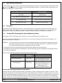
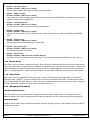
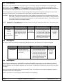
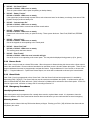
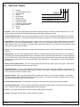
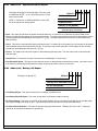
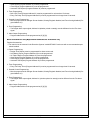
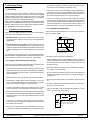
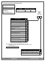
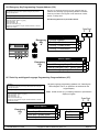
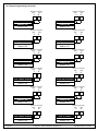
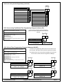
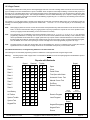
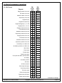
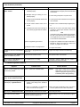
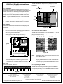
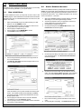
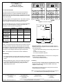
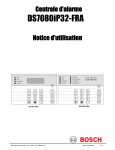
Installation Considerations
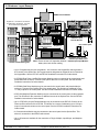
Proper location of detection devices is one of the most critical factors in a fire alarm system.
The following are some general considerations:
• Smoke detectors should not be installed in “dead air” spaces or close to ventilating or air conditioning outlets because
smoke may be circulated away from the detector. Locations near air inlets should be favored.
• Avoid areas subject to normal smoke concentrations such as kitchens, garages, or near fireplaces.
• Do not install smoke detectors where normal area temperatures are above 100 degrees F (38 degrees C) or below 32
degrees F (0 degrees C).
• Areas of high humidity and dust concentrations should be avoided.
Page 14
Copyright © 1996 Detection Systems, Inc.
DS7060 User Guide
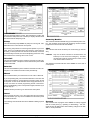
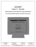
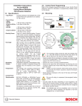
• The edge of ceiling mounted detectors should be no closer than 4 inches (10 cm) from any wall.
• Place the top edge of wall mounted detectors between 4 and 12 inches (10 to 30 cm) from the ceiling.
Bedroom
Living
Room
Basement
*
*
Hall
Dining
Room
Bedroom
*
*
Kitchen
Living Room
Dining
Room
Bedroom
Rec Room
*
Bedroom
*
*
Bedroom
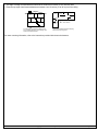
= Smoke Detector
= Smoke Detector
A smoke detector should be located on each
story including basements, but excluding crawl
spaces and unfinished attics.
Locate smoke detectors between sleeping
areas and family living areas.
For exact mounting information, refer to the instructions provided with the smoke detectors.
DS7060 User Guide
Copyright © 1996 Detection Systems, Inc.
Page 15
Index
A
S
Arming
Force Arming
7
Quick Arming
6
Turning ON (Arming) the System
Auto Bypass
7
Silencing Alarms
T
5
Tests
Communicator Test
9
Local Battery/Sounder Test
C
Chime Mode
12
9
Z
8
Zone
Bypass
7
Test
8
D
Disarming
Turning OFF (disarming) the System/Silencing Alarm
Duress Code
12
6
E
Easy Exit
6
Emergency Alarm Keys
13
Emergency Keypad Alarms
13
Emergency Procedures
12
Error Displays
11
F
Fire
Alarms
13
Reset
10
Safety
14
Trouble
10
G
Guest Code
12
H
Help key
13
I
Identifying Alarm Sounds
12
K
Keypads
Backlight Control
3
DS7443
3
DS7445
3
DS7447
3
Volume Control
3
M
Master Code
4
P
Panic key
13
Personal Identification Numbers
Adding a PIN
4
Removing a PIN
4
4
R
Read Alarm History
10
Remote Program Dial-out and Answer
11
Remote Programming
Answer for Remote Programming
11
Call for Remote Programming
11
Page 16
Copyright © 1996 Detection Systems, Inc.
DS7060 User Guide
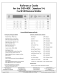
Reference Guide
for the
DS7060 Control/Communicator
Armed
1
4
Status
2
3
5
6
Power
Fire
Armed
®
Status
®
Power
Fire
2
3
Off
4
5
6
Perimeter
Only
7
8
9
No
Entry
*
0
#
Bypass
Perimeter
Status
Supervisory
Power
Bell Silenced
Fire
Trouble
1 2 3 4 5 6 7 8
On
On
1
Armed
1
2
3
Off
On
4
5
6
Perimeter
Only
7
8
9
No
Entry
*
0
#
Bypass
1
2
3
Off
4
5
6
Perimeter
Only
7
8
9
No
Entry
*
0
#
Bypass
System
Reset
System
Reset
®
System
Reset
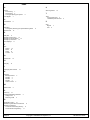
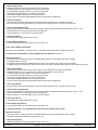
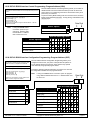
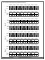
Keypad Quick Reference Guide
Turning On (arming) your System
Normal Arming
PIN + [On]
Perimeter Arming, no entry delay
PIN + [No Entry] [Perimeter Only]
Perimeter Arming, with entry delay
PIN + [Perimeter Only]
Maximum Security Arming
PIN + [No Entry] [On]
Force Arming
PIN + Arming Sequence + [Bypass]
Zone Bypass
PIN + [Bypass] followed by the Zone number
Quick Arm
[#] + [On]
Turning Off (disarming) your System
PIN + [Off]
Commands for other System Features
Chime Mode
PIN + [#] [7]
Zone Test
PIN + [#] [8] [1]
Read Alarm History
PIN + [#] [8] [9]
Battery Test
PIN + [System Reset]
Communicator Test
PIN + [#] [8] [2]
Fire Reset
PIN + [System Reset]
Fire Trouble
PIN + [Off] to silence, PIN + [System Reset] to clear
Remote Program Dial Out
PIN + [#] [8] [3]
Remote Program Answer
PIN + [#] [8] [6]
Local Battery/Sounder Test
PIN + [#] [8] [5]
Error Display
PIN + [#] [8] [7]
Error Display Reset
PIN + [System Reset]
Clear Zone Bypass
PIN + [Bypass] [*] to clear
Guest Code Enable
PIN + [#] [8] [4]
NOTE: Examples are shown in Commercial Mode but are valid for any mode.
Detection Systems PTY Ltd.
Unit 21, 45 Gilby Road
Mount Waverley, Victoria 3149, Australia
61 3 9558 8088
Fax: 61 3 9558 8089
Copyright © 1996 Detection Systems, Inc.
Detection Systems PTY Ltd.
Unit 2, The Riverside Centre
148 James Ruse Drive
Parramatta, NSW 2150, Australia
61 2 891 4944
Fax: 61 2 891 5844
Detection Systems Ltd.
19, Rue du 19 Mars-78130
Les Mureaux, France
Phone/Fax: 33 1 34 74 9576
Detection Systems, Inc., 130 Perinton Parkway, Fairport, New York, USA 14450-9199
(716) 223-4060 • (800) 289-0096 • Fax: (716) 223-9180
Detection Systems Ltd.
Unit 13-18, 17/F New Commerce Centre
19 On Sum Street, Shatin, N.T.
Hong Kong
852 2635 2815
Fax: 852 2648 7986
DS7060 Reference Guide P/N 30658 B
TABLE OF CONTENTS
1.0 SYSTEM OVERVIEW ......................................................................................................................................................... 5
2.0 SPECIFICATIONS .............................................................................................................................................................. 5
2.1
2.2
2.3
2.4
2.5
2.6
2.7
2.8
2.9
2.10
2.11
Enclosure Housing .................................................................................................................................................. 5
Temperature ............................................................................................................................................................ 5
Power ...................................................................................................................................................................... 5
Outputs .................................................................................................................................................................... 5
Zones ....................................................................................................................................................................... 5
Keypads ................................................................................................................................................................... 5
Communicator ......................................................................................................................................................... 5
Users ....................................................................................................................................................................... 5
Lightning Protection ................................................................................................................................................ 5
Burglar/Fire Zone Inputs .......................................................................................................................................... 5
Line Seizure Notice ................................................................................................................................................. 5
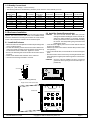
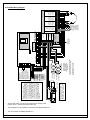
3.0 ENCLOSURE INSTALLATION ........................................................................................................................................... 6
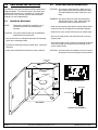
3.1
3.2
Install the Enclosure ................................................................................................................................................ 6
Install the Control/Communicator ............................................................................................................................ 6
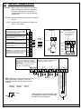
4.0 CONTROL TERMINAL WIRING ........................................................................................................................................7
5.0 OPERATING GUIDE ........................................................................................................................................................... 8
5.1
5.2
Understanding the DS7443, DS7445, and DS7447 Keypads ................................................................................. 8
Personal Identification Numbers .............................................................................................................................. 9
Adding a PIN ........................................................................................................................................................................ 9
Removing a PIN ................................................................................................................................................................... 9
5.3
5.4
5.5
5.6
Turning ON (arming) the System ........................................................................................................................... 10
Quick Arming the System ...................................................................................................................................... 11
Easy Exit ................................................................................................................................................................ 11
Turning OFF (disarming) the System/Silencing Alarms ......................................................................................... 11
5.7
5.8
5.9
5.10
5.11
5.12
5.13
5.14
5.15
Force Arming ......................................................................................................................................................... 12
Auto Bypass .......................................................................................................................................................... 12
Zone Bypass .......................................................................................................................................................... 12
Chime Mode .......................................................................................................................................................... 13
Zone Test ...............................................................................................................................................................13
Local Battery/Sounder Test .................................................................................................................................... 14
Communicator Test ................................................................................................................................................ 14
Read Alarm History ................................................................................................................................................ 15
Fire Reset/Fire Trouble .......................................................................................................................................... 15
Turning Off (disarming) the System under Duress ............................................................................................................. 11
Fire Reset ........................................................................................................................................................................... 15
Fire Trouble ........................................................................................................................................................................ 15
5.16
Remote Program Dial-out and Answer .................................................................................................................. 16
Call for Remote Programming ............................................................................................................................................ 16
Answer for Remote Programming ...................................................................................................................................... 16
5.17
5.18
5.19
5.20
Error Displays ........................................................................................................................................................ 16
Duress Code .......................................................................................................................................................... 17
Guest Code............................................................................................................................................................ 17
Emergency Procedures ......................................................................................................................................... 17
Identifying Alarm Sounds ................................................................................................................................................... 17
Silencing Alarms ................................................................................................................................................................. 17
A Cautionary Note .............................................................................................................................................................. 18
Above All Else, Common Sense Should Prevail ................................................................................................................ 18
Caution When Entering A Building ..................................................................................................................................... 18
Fire Alarms ......................................................................................................................................................................... 18
5.21
Page 2
Emergency Keypad Alarms ................................................................................................................................... 18
Copyright © 1996 Detection Systems, Inc.
DS7060 Reference Guide
5.22
Fire Safety ............................................................................................................................................................. 19
If Installed in Family Residences ........................................................................................................................................ 19
Having and Practicing an Escape Plan .............................................................................................................................. 19
Installation Considerations ................................................................................................................................................. 19
6.0 SYSTEM WORKSHEETS ................................................................................................................................................ 21
7.0 HOW TO PROGRAM THE DS7060 ................................................................................................................................. 23
8.0 PROGRAMMING THE DS7060........................................................................................................................................ 23
8.1
8.2
8.3
8.4
8.5
8.6
8.7
8.8
8.9
8.10
8.11
8.12
8.13
8.14
8.15
8.16
8.17
8.18
8.19
8.20
8.21
8.22
8.23
8.24
8.25
8.26
8.27
8.28
8.29
8.30
8.31
8.32
8.33
8.34
8.35
8.36
8.37
8.38
Address 01 - Zone Programming .......................................................................................................................... 24
Address 02 - Zone Bypass .................................................................................................................................... 25
Address 03 - Zone Action ......................................................................................................................................26
Address 04 - Output Type ......................................................................................................................................26
Address 05 - Zone Response Time ....................................................................................................................... 27
Address 06 - Programmed Response Time .......................................................................................................... 27
Address 07 - Zone Restoral Options ..................................................................................................................... 27
Address 08 - Outputs ............................................................................................................................................. 28
Address 09 - User Control ..................................................................................................................................... 29
Address 10 - General Control ................................................................................................................................ 30
Address 11 - Keypad Assignment .......................................................................................................................... 31
Address 12 thru 18 - Alpha Label .......................................................................................................................... 31
Address 19 - Special Keys .................................................................................................................................... 32
Address 20 - Report Control .................................................................................................................................. 32
Address 21 - Phone Number Control .................................................................................................................... 33
Address 22 - Dial Attempts .................................................................................................................................... 33
Address 23 - Time Delays ..................................................................................................................................... 34
Address 24 - Keypad Report ................................................................................................................................. 34
Address 25 - Zone Alarm Report ........................................................................................................................... 35
Address 26 - Zone Alarm Restoral Report ............................................................................................................. 35
Address 27 - Zone Trouble Report ........................................................................................................................ 35
Address 28 - Zone Trouble Restoral Report .......................................................................................................... 36
Address 29 - Zone Bypass Report ........................................................................................................................ 36
Address 30 - Zone Bypass Restoral Report .......................................................................................................... 36
Address 31 - Open/Close Duress Report .............................................................................................................. 37
Address 32 - Battery, AC Report ............................................................................................................................ 37
Address 33 - Programming Report ........................................................................................................................ 38
Address 34 - System Report ................................................................................................................................. 38
Address 35 - Exit Error, Recent Closing, Comm. Failure Report ........................................................................... 38
Address 36 - Test Reports, System Test ................................................................................................................ 39
Address 37 - Account Codes ................................................................................................................................. 39
Address 38 - Phone #1 Format .............................................................................................................................40
Address 39 - Phone #2 Format .............................................................................................................................40
Address 40-41 Phone #1 (Reporting) .................................................................................................................... 40
Address 42-43 Phone #2 (Reporting) .................................................................................................................... 40
Address 44-45 Phone #3 (Remote Programming) ................................................................................................ 40
Address 46 - Programmer & Master Codes .......................................................................................................... 41
Address 47 - Default EEPROM .............................................................................................................................41
Address 48 - Automatic Test Report Interval ......................................................................................................... 41
Address 49 - Hours to First Auto Test Report ........................................................................................................ 41
Address 50 - AC Failure Report Delay .................................................................................................................. 41
9.0 INSTALLATION GUIDE FOR U. L. LISTED SYSTEMS .................................................................................................. 42
9.1
9.2
9.3
DS7060 U. L. Listings ............................................................................................................................................ 42
Installation Considerations .................................................................................................................................... 42
Programming the DS7060 ..................................................................................................................................... 43
Household Fire Alarm (using Digital Alarm Communicator Transmitter with local bell) ...................................................... 43
Grade A Household Burglary Alarm (using Digital Alarm Communicator Transmitter with local bell) ................................ 43
Local Burglary Alarm .......................................................................................................................................................... 44
Grade A Installations using Digital Alarm Communicator Transmitter with local bell .................................................. 44
DS7060 Reference Guide
Copyright © 1996 Detection Systems, Inc.
Page 3
Police Station Connection .................................................................................................................................................. 45
Grades AA and A Installations using the Applied Spectrum PAL200 and the DACT ................................................... 45
Grade A Installations using Digital Alarm Communicator Transmitter with local bell .................................................. 45
Central Station Burglary Alarm ........................................................................................................................................... 46
Grades AA and A Installations using the Applied Spectrum PAL200 and the DACT ................................................... 46
Grade B Installations using Digital Alarm Communicator Transmitter with local bell .................................................. 46
Grade C Installations using Digital Alarm Communicator Transmitter only ................................................................. 47
9.4
Wiring and Programming Information for Installations Using the Ademco AB-12 Bell/Housing ............................ 48
10.0 FCC COMPLIANCE NOTICE ........................................................................................................................................... 48
11.0 FCC PHONE CONNECTION NOTICE TO USERS .......................................................................................................... 48
12.0 CANADIAN DEPARTMENT OF COMMUNICATIONS ..................................................................................................... 49
12.1
12.2
12.3
General Installation Requirements ........................................................................................................................ 49
Terminal Requirements .......................................................................................................................................... 49
RFI Requirements ................................................................................................................................................. 49
13.0 FOR INSTALLATIONS IN NEW ZEALAND ..................................................................................................................... 49
14.0 REPORT PROGRAMMING .............................................................................................................................................. 50
14.1
Suggested Values .................................................................................................................................................. 50
Personal Dialing Format ..................................................................................................................................................... 50
Pager Format ..................................................................................................................................................................... 51
4/2 Format (suggested values) .......................................................................................................................................... 52
14.2
Values Sent ............................................................................................................................................................ 53
High Speed 4/9 Format ...................................................................................................................................................... 53
Contact ID Format .............................................................................................................................................................. 55
15.0 PROGRAM ADDRESSES QUICK REFERENCE ............................................................................................................ 57
Page 4
Copyright © 1996 Detection Systems, Inc.
DS7060 Reference Guide
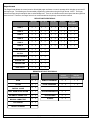
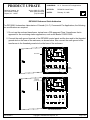
1.0
2.5
SYSTEM OVERVIEW
Zones
2.0
SPECIFICATIONS
• 6 zones
• Zone Response Time: All six zones can be programmed
to respond at either 300 ±100 ms or a programmable time
(common to all zones) that can be configured to be
between 10 ms and 2.5 seconds. Zones are ignored for 5
seconds after power up, and for two seconds after a
system reset.
2.1
Enclosure Housing
Refer to Sections 8.2 - 8.7 for detailed zone operation.
The DS7060 Control/Communicator is a fully integrated
hard-wire security and residential fire alarm system. It can
support up to 6 input zones and 15 individual users. Up to 4
keypads may be used to provide user interface with the
system, as well as programming access for the installer.
The enclosure is manufactured from 22 Ga. (0.65 mm),
cold-rolled steel, and measures 9.25" Wide, by 10.25" High,
by 3" Deep (23.5 cm Wide, by 26 cm High, by 7.6 cm Deep).
The door has a knockout for a standard DS lock (optional).
The enclosure has a slot in the back and also has an
optional tamper switch mounting bracket with a plunger
switch.
2.2
Temperature
• Operating temperature:
• Storage temperature:
2.3
2.6
• Total number of keypads:
4 Keypads
• Maximum wire length total in system: 1000 ft. (305 m)
• Wire type:
22 AWG (0.8 mm)
NOTE: Keypads may be up to 1000 ft. (305 m) from the
panel when #22 (0.8 mm) wire is used and only one
keypad is connected to a particular wire run.
2.7
+32°F to +120°F
(0°C to +49°C)
-20°F to +150°F
(-28°C to +66°C)
Keypads
Communicator
Will report to two phone numbers with full single, double, and
backup reporting. Communicated in 3/1, 3/1E, 3/1 with
Parity, 3/1E with Parity, 4/1, 4/2, High Speed 4/9, Pager,
Contact ID, and Personal Dialing formats.
Power
• Input Power: 16.5 VAC (U.S.) 16 VAC (Aust), 20 VA, 50
or 60 Hz
• Auxiliary Regulated Power: 12-12.5 VDC, 0.8 A
• Auxiliary Power Voltage Range: 10 to 13.8 VDC
• Optional Standby battery (P334): 12 V, 7.0 AH
• Control Panel Current Draw: 65 mA
• DS7443 Keypad Current Draw: 45 mA, Standby
45 mA, Alarm
• DS7445 Keypad Current Draw: 75 mA, Standby
75 mA , Alarm
• DS7447 Keypad Current Draw: 100 mA, Standby
100 mA, Alarm
• Fuse 1 & Fuse 2:
1 A, 250 V
Refer to Sections 8.14 - 8.33 for communicator operation.
2.4
MOVs and/or spark gaps provide protection from lightning
surges and static discharges.
Outputs
The ringer equivalence is 0.1 B.
2.8
Users
The system allows up to 15 individual users. Each user will
have his own PIN number (the 4 digit code entered at the
keypads).
Refer to Section 5.2 for PIN programming.
2.9
Lightning Protection
• Programmable Output 1*
Solid state, switch to ground
(500 mA max.).
2.10 Burglar/Fire Zone Inputs
• Programmable Output 2*
Solid state, switch to ground
(500 mA max.).
• Number of Circuits:
• End-of-Line Resistor:
• Programmable Output 3*
Form “C” relay contacts
available. Typical: Normally
Open contacts that switch to
12 V @ 800 mA.
NOTE: 4 wire type smoke detectors only.
* = Current draw should be subtracted from either maximum auxiliary or maximum alarm current draw.
6 Circuits on board
2.21k ohms
2.11 Line Seizure Notice
This control panel incorporates a line seizure feature which
will disable internal telephone lines when the control panel is
sending alarm or supervision reports to the central station.
Refer to Section 8.8 for detailed Output operation.
DS7060 Reference Guide
Copyright © 1996 Detection Systems, Inc.
Page 5
3.0
ENCLOSURE INSTALLATION
3.2
The DS7060 control/communicator and the enclosure are
shipped together. The control, however, still needs to be
installed into the enclosure. Hardware for mounting the
enclosure to a wall, and the control to the enclosure is
located in its own hardware pack.
3.1
NOTE:
Install the Control/Communicator
CAUTION: The control is static sensitive. Make sure you
touch earth ground before handling the control.
This will discharge any static electricity in your
body.
EXAMPLE: Run the ground wire to the enclosure before
handling the control. Then, keep holding the
ground wire while installing the control.
Install the Enclosure
This panel is intended for mounting in a restricted access area and should be wall
mounted.
CAUTION: The control panel should only be installed by
authorized service personnel.
• Use the enclosure as a template and mark the mounting
holes on the mounting surface.
• Pre-start the mounting screws for these holes. Mount the
enclosure.
• Knock out the desired wire entrances on the enclosure.
• Insert the two support posts into the control retainer holes
as shown below in the Support Post Assembly diagram.
• Slide the top of the control PCB into the two retainer tabs.
• Once in the retainer tabs, the control will rest on the two
support posts.
• Secure the bottom of the enclosure by screwing the bottom
two holes through the support posts and through to the
control retainer holes.
CAUTION: Once the control is installed, be sure to connect
its ground wire to the top hinge of the enclosure.
Retainer Tabs
AC AC PO1 12V
F1
RED BLK GRN YEL
Mounting Holes
Ground Tab
Control Retainer
Holes
RED BLK
F2
POC
-
PO3
1
-
2
3
-
4
5
-
6
T
TH RH
R
CONTROL/COMMUNICATOR
Enclosure
Mounting
Hole
Wire
Entrances (4)
Mounting
Hole
Circuit board
ENCLOSURE
SUPPORT POST ASSEMBLY
Page 6
Copyright © 1996 Detection Systems, Inc.
DS7060 Reference Guide
4.0
CONTROL TERMINAL WIRING
WARNING: Before servicing this equipment, remove all
power including the transformer and battery.
Also remove the phone line connection. A
complete functional test is required after any
programming.
CAUTION: Incorrect connections may result in damage to
the unit.
NOTE: Shared cable is not allowed for keypad, telephone, or siren wiring.
Typical Burglar Alarm
Loop Wiring
PO2
RED
KEYPADS: Up to 4 keypads may be used. BLK
Maximum wire length is 1000 ft. (305 m) of
22 AWG (0.8 mm) .Can be “home-run” or GRN
“daisy-chained.” Protected by Fuse 2.
YEL
)+(
)-(
PO2
Zone 1-6
12 V
12V
Fuse 1
)-( 1 A, 250 V
Common (-)
PO1
NOTE: 2 wire smoke detectors
cannot be used with
this equipment.
Zone 1-6
AC
Typical 4 Wire Smoke
Detector Wiring
Common (-)
AC
1
2
3
4
5
6
7
8
9
Zone input
EARTH GROUND: Must be connected to
a good earth ground such as a cold water
pipe and also connected to the cabinet cover,
using the supplied wire jumper.
A/C INPUT: Use U. L. listed 16.5 VAC
20 VA, Class 2 transformer Model TR-16.
Requires 50/60 Hz unswitched dedicated
outlet - Do Not Share
PROGRAMMABLE OUTPUT 1: Shorts to
common (-) when activated, 500 mA max,
protected by Fuse 1.
PROGRAMMABLE OUTPUT 2: Shorts to
common (-) when activated, 500 mA max,
protected by Fuse 1.
5
6
Zone 1-6
Smoke
Detector
NO
Fuse 2
1 A, 250 V
NO
EOL
Resistor
NC
EOL
Relay
NOTE: EOL Relay shown in de-energized
(power off) condition.
10
POC: The POC terminal is tied to a 12 volt
fused line and can be used as a second
continuous 12 volt terminal, provided the
800 mA supply current is not exceeded (see
Section 2.4).
PO3: Provides 12 V @ 800 mA when
activated. Protected by Fuse 2.
POC - PO3
ZONES 1-6: (Supervised) Zones are
intended for connection of Normally Open or
Normally Closed alarm contacts.
1
-
2
+
3
+
-
4
+
5
+
-
6
+
PHONE
T TH RH R
800 mA - 400 mA = 400 mA
available
keypads
at PO3
+
- Battery
RED
BLK
DS7060 Reference Guide
Ring Telco Line (RED)
EOL 2.2kΩ
Ring House Phones (GRAY)
NOTE: PO3 output current is 800 mA minus the
total keypad current. Example: If four 7447
keypads at 100 mA each are used, the current
is 400 mA.
(+)
Tip House Phones (BROWN)
(-)
Tip Telco Line (GREEN)
11 12 13 14 15 16 17 18 19 20 21 22 23 24 25 26
Panel Grounds are indicated by black areas
surrounding the numbers of corresponding
terminals on the wiring diagram.
Copyright © 1996 Detection Systems, Inc.
Page 7
5.0
OPERATING GUIDE
5.1
Understanding the DS7443, DS7445, and DS7447 Keypads
The DS7443 is a 6 zone LED keypad; its LEDs represent the zones of the system.
The DS7445 is an 8 zone LED keypad; its LEDs represent the zones of the system (LEDs for zones 7 and 8 are not used).
The DS7447 is an alpha-numeric LCD keypad.
All three keypads display information on various control panel functions. A built-in sounder is used to annunciate keystroke
entries and as an interior warning device.
Volume Control (DS7445 and DS7447 only): The keypad sounder volume can be adjusted using the [1] and [4] keys along
with the [*] key. Hold the [*] key while pressing the [1] key to increase the volume or the [4] key to decrease the volume. The
volume adjustment does not affect the volume during an alarm.
Backlight Control (DS7447 only): The display backlight intensity can be adjusted using the [3] and [6] keys along with the
[*] key. Hold the [*] key while pressing the [3] key to increase the brightness or the [6] key to decrease the brightness.
NOTE: After the backlight and volume are adjusted, you must arm, then disarm the system once to store this information in
the control panel. If power is disconnected before the panel is armed, the backlight and volume levels will return to
the default settings.
Armed
1
4
Status
2
3
5
6
Power
Fire
Armed
®
Status
®
Power
Fire
2
3
Off
Perimeter
Only
4
5
6
7
8
9
No
Entry
*
0
#
Bypass
Perimeter
Status
Supervisory
Power
Bell Silenced
Fire
Trouble
1 2 3 4 5 6 7 8
On
On
1
Armed
1
2
3
Off
4
5
6
Perimeter
Only
7
8
9
No
Entry
*
0
#
Bypass
On
1
2
3
Off
4
5
6
Perimeter
Only
7
8
9
No
Entry
*
0
#
Bypass
System
Reset
System
Reset
DS7447 KEYPAD
®
System
Reset
DS7443 KEYPAD
DS7445 KEYPAD
This chart will help you understand what each Light/LED represents.
LIGHT
OFF
Armed
(red)
The control panel is disarmed.
An exit delay is in progress or an alarm
has occurred.
The control panel is armed and no alarms have
occurred.
Status
(green)
One or more zones are not ready
to arm.
One or more zones are bypassed.
All zones are ready to arm.
Power
(green)
The control panel has lost power.
No AC or battery.
Control panel problems. See Section 5.17,
Error Displays.
Normal operation.
There are no fire alarms.
A fire zone is in alarm.
A fire trouble condition exists.
The perimeter is not armed.
This light will not flash.
The perimeter is armed.
Supervisory*
(yellow)
This light will not be used by the
DS7060.
Not used.
Not used.
Bell Silenced*
(yellow)
The bells do not need to be or
have not been silenced.
This light will not flash.
The bells have been silenced. To clear, enter the
Fire Reset command.
There are no trouble conditions.
This light will not flash.
A trouble condition exists.
There are no zone alarms.
A zone (1-6) is in alarm.
A zone (1-6) is not ready to arm or if a fire zone, a
trouble condition exists.
Fire
(red)
Perimeter*
(yellow)
Trouble*
(yellow)
Zone LEDs**
(red)
FLASHING
* = This light is present on the DS7445 only.
Page 8
ON
** = This light is present on the DS7443 and DS7445.
Copyright © 1996 Detection Systems, Inc.
DS7060 Reference Guide
5.2
Personal Identification Numbers
The Personal Identification Number (PIN) is the 4-digit code users enter at the keypad to gain access to the system. A PIN
may be assigned to each User Number 001-015. The User Number identifies each person using the system. There are 15
possible User Numbers (001-015).
Your system may have up to 15 different PINs, each 4 digits long. Each User Number can have only one PIN. Attempting
to assign the same PIN to multiple User Numbers will result in the three-beep error tone, and the change will not be made.
User Number 001 is designated as a Master Code. It can be used to add, delete, read back, or change other PINs.
User Number 001 is shipped from the factory with the sequence of 1234. This code should be changed to one of your
personal preference. PINs should never be programmed with common sequences such as 1111 or 2468 because they are
easily violated.
Adding a PIN
The following chart will guide you through the steps necessary to add or change a PIN. It is recommended that this procedure be performed at a DS7447 keypad. No visual cues will be given from a DS7443 or DS7445 keypad.
STEPS TO CHANGE
A PIN
COMMAND SEQUENCE
IF ACCEPTED,
THE DISPLAY READS
#1 Enter the Master Code
Programming Mode
[Master Code] + [#] [0]
#2 Enter the User Number
[0] [0] [1] through [0] [1] [5]
"Enter PIN"
#3 Enter the PIN
Any 4 digits (Each user
must have a different PIN).
Enter PIN Again
End with #
#4 Enter the PIN again followed
by the [#] key.
PIN (same 4 digits as above)
then [#]
"Enter User No."
(001 . . 015)
A long beep will sound to
signify acceptance of
the new PIN.
NOTE: Users 014 and 015 may be used for Duress and Guest Codes. See Sections 5.18 and 5.19, Address 09 - User
Control for more information.
NOTE: You cannot read back User PIN numbers. You should keep a separate list for future reference. See Page 22.
Removing a PIN
To remove a PIN enter a [Master Code] [#] [0], the User Number of the PIN to be canceled, and then [#] again. User Number
001 can not be canceled. See Section 8.9 for special uses for User Number 14 and 15 PINs.
DS7060 Reference Guide
Copyright © 1996 Detection Systems, Inc.
Page 9
5.3
Turning ON (arming) the System
The green Status light must be on steady and no zone lights are displayed on the DS7443 or DS7445 keypad. The DS7447
display must read “Ready To Arm” in order to arm the system with one of these commands.
If the green Status light is not on, or zone lights are displayed on the DS7443 or DS7445 keypad, or if the DS7447's display
is reading “Not Ready,” then see Section 5.7 Force Arming or Section 5.9 Zone Bypass for other ways to arm the system.
This chart explains the five normal ways of arming the system.
TYPE OF ARMING
DESIRED
COMMAND
SEQUENCE
Normal Arming
No one left on the
premises.
An entry/exit delay
is in effect.
Commercial Mode
PIN + [On]
Perimeter Instant
Arming
Someone still on the
premises.
There is NO entry
delay in effect.
Commercial Mode
PIN + [No Entry] +
[Perimeter Only]
Perimeter Arming
Someone still on the
premises.
An entry/exit delay
is in effect.
Commercial Mode
PIN + [Perimeter Only]
Maximum Security
Arming
No one left on the
premises.
There is NO entry delay
in effect. An alarm WILL
occur upon entry.
Commercial Mode
PIN + [No Entry] [On]
Residential Mode
[#] + [On]
Residential Mode
[#] + [No Entry] +
[Perimeter Only]
Residential Mode
[#] + [Perimeter Only]
Residential Mode
[#] + [No Entry] + [On]
WHAT WILL HAPPEN
•
•
•
•
WHAT TO DO
The red Armed Light will begin to flash.
The green Status light will turn off.
“Armed” will be displayed (DS7447).
“Exit Now” will display (DS7447) during the exit delay
interval.
• A single beep will sound.
• The red Armed light will turn on steady after the exit
delay interval.
Exit during the exit
delay interval.
• The red Armed Light will begin to flash.
• “Perimeter Inst.” will be displayed (DS7447).
• “Exit Now” will display (DS7447) during the exit delay
interval.
• A single beep will sound.
• The red Armed light will turn on steady after the exit
delay interval.
• The yellow Perimeter light (DS7445) will turn on
steady.
• Only exterior protection zones will be armed.
Move freely around
the interior.
• The red Armed Light will begin to flash.
• “Perimeter On” will be displayed (DS7447).
• “Exit Now” will display (DS7447) during the exit delay
interval.
• A single beep will sound.
• The red Armed light will turn on steady after the exit
delay interval.
• The yellow Perimeter light (DS7445) will turn on
steady.
• Only exterior protection zones will be armed.
Move freely around
the interior.
•
•
•
•
The red Armed Light will begin to flash.
The green Status light will turn off.
“Armed Instant” will be displayed (DS7447).
“Exit Now” will display (DS7447) during the exit delay
interval.
• A single beep will sound.
• The red Armed light will turn on steady after the exit
delay interval.
Exit during the exit
delay interval.
CAUTION:
Violating any zone
after the exit delay
interval will cause an
instant alarm.
NOTE: In commercial burglar applications for U. L. Certificated systems, a ring-back indication and bell test should be heard
after arming (closing). If not heard, call for service.
NOTE: If the system has invisible zones that are not ready, they will be displayed during the arming sequence. The display
of invisible zones will remain on until the zone is cleared or bypassed.
Page 10
Copyright © 1996 Detection Systems, Inc.
DS7060 Reference Guide
5.4
Quick Arming the System
If Quick Arming is not used, a PIN must be entered at the beginning of all arming command sequences. When Quick Arming
is used, the following shortcuts are available. Quick Arming is disabled by default. To select the Quick Arming feature, see
Section 8.10, Address 10 - General Control.
QUICK ARMING COMMAND SEQUENCE
TYPE OF ARMING
[#] + [On]
Normal Arming
[#] + [No Entry] + [Perimeter Only]
5.5
Perimeter Instant Arming - no entry delay
[#] + [Perimeter Only]
Perimeter Arming - entry/exit delay
[#] + [No Entry] + [On]
Maximum Security Arming
Easy Exit
If the system is armed and there have been no zones violated, then you can reenter a Quick Arm Command without first
disarming the system. This allows you to change the arming level or to restart the exit delay so you can exit through an
entry/exit zone. Easy Exit is disabled by default. To select the Easy Exit feature, see Section 8.10, Address 10.
5.6
Turning OFF (disarming) the System/Silencing Alarms
Please read Section 5.20 Emergency Procedures prior to being confronted with an emergency event.
If you have entered the building through a perimeter door, you may hear a steady pre-alert tone from the keypads. If so,
disarm according to the chart below.
WARNING: If the bells and sirens are on and/or the red Armed light is flashing, then the keypad is signaling that an alarm
has occurred sometime before your arrival. The DS7447 will display “Zone Alarm.” The DS7443 or DS7445
zone LEDs will be flashing for the corresponding zone that is in alarm.
• The keypad will also issue a pulsed tone during the entry delay instead of the usual steady tone.
• If the alarm has not been previously investigated, do not enter the building unless accompanied by the appropriate Emergency Services’ personnel.
This chart explains proper procedures for disarming and/or silencing alarms.
TYPE OF DISARMING
COMMAND
SEQUENCE
WHAT WILL HAPPEN
Disarming the System
PIN + [Off]
The red Armed light will turn off.
Pre-alert sounders will silence.
Silencing Alarms
PIN + [Off]
The red Armed light will turn off.
Zone LEDs on the DS7443 or
DS7445 will turn off.
Alarms in progress will silence.
Turning Off (disarming) the System under Duress
A duress code is used when someone demands, by threatening your life or well-being, that the system be turned off. When
used, the code will both turn off the system and report a silent duress alarm if connected to a monitoring service. User code
14 can be optionally configured as a duress code. User code 14 will not arm the system, or report duress, if the system is not
armed. Extreme care should be used when entering your PIN to turn off the system, so a duress code is not inadvertently
entered. User Code 14 is not a duress code by default. You must program the control panel that User Code 14 is the duress
code. See Section 8.9, Address 09 for more information.
DS7060 Reference Guide
Copyright © 1996 Detection Systems, Inc.
Page 11
5.7
Force Arming
When one or more zones are faulted, the system may be Force Armed (if programmed at Address 10) by bypassing the
faulted zones. The green Status light will be off on all keypads when Force Arming is required to arm the system. The
DS7447 display will read “Not Ready” or “Fire Trouble” (if a fire zone is open) and the DS7443 and DS7445 zone LEDs (16) will be on if one of those zones is faulted. See Section 8.10 to enable Force Arming.
Force Arming during an AC power failure: Regular arming of the control panel is not permitted during an AC power failure.
Having to Force Arm serves as a warning that the control panel is operating under backup battery.
WARNING: Bypassing or Force Arming removes some of your building's protection because it excludes the faulted zones
from arming. Therefore, an intrusion may not be detected or the detection may be delayed. Always attempt to
correct any zone problems (close doors and windows, etc.) before using these features. If the problem can not
be corrected, contact your installing company.
NOTE: See Section 5.9 Zone Bypass for an alternate method of arming the system when faults exist. Force arming is not
available in U. L. Listed systems.
TYPE OF ARMING
WHAT WILL HAPPEN
Force
Arming
• A 5 second beep occurs,
indicating there are faulted
zones and that the control
Enter any
panel needs to be Force
arming sequence.
Armed.
5.8
WHAT TO DO
WHAT WILL HAPPEN
WHAT TO DO
Press [Bypass] • The red Armed light will flash
during the
during the exit delay interval.
5 second beep. • The control panel will arm with
the faulted zones bypassed, or
a three-beep error tone will occur
indicating Force Arming has not
been accepted or allowed.
Exit during the
exit delay
interval if
leaving.
Auto Bypass
The system can be armed and will automatically bypass faulted zones. See Section 8.10 to enable Auto Bypass.
5.9
TYPE OF ARMING
WHAT WILL HAPPEN
Auto Bypass
• A single beep occurs,
indicating that the panel
has armed.
WHAT WILL HAPPEN
• The red Armed light will flash
during the exit delay interval.
• The control panel will arm with
the faulted zones bypassed, or
a three-beep error tone will occur
indicating Auto Bypass has not
been accepted or allowed.
WHAT TO DO
Exit during the
exit delay
interval if
leaving.
Zone Bypass
There may be occasions when it is desirable or necessary to temporarily bypass one or more zones prior to arming the
system. Bypass commands only work when the control panel is disarmed. For instance, an open window may cause the
DS7447 display to read "Not Ready" followed by the zone number. The DS7443 or DS7445 may have one of its zone LEDs
on steady.
Only one zone may be bypassed each time the command is used. If more than one zone requires bypassing, repeat the
command for each zone to be bypassed.
NOTE: See Section 5.7 Force Arming for another method of zone bypassing.
Page 12
Copyright © 1996 Detection Systems, Inc.
DS7060 Reference Guide
This chart explains the procedure for bypassing a faulted zone prior to arming the system.
TYPE OF BYPASSING
DESIRED
Bypass Faulted
Zones
Read Bypassed
Zones
Clear Individual
Bypassed Zone(s)
COMMAND
SEQUENCE*
PIN + [Bypass] [Zone #] • The Status light will begin to flash if no
other zones are violated.
PIN + [Bypass]
• Bypass will be displayed (DS7447)
followed by the zone number of any
bypassed zones. The DS7443 or
DS7445 will flash the zone LED of the
zone being bypassed.
PIN + [Bypass] [Zone #] • Individual zone bypasses will be cleared.
PIN + [Bypass] [*]
Clear all
Bypasses
WHAT WILL
HAPPEN
• All bypasses will be cleared.
* If in “Residential Mode” substitute the [#] key for the PIN.
NOTE: All bypasses are cleared when the system is disarmed, unless they are on 24-hour zones. To clear a bypass on a
24-hour zone, use Clear Individual or Clear All.
5.10 Chime Mode
Chime Mode causes the keypad sounders to beep each time a Perimeter or Entry/Exit zone is violated while the control
panel is off (disarmed). The [#] [7] command is used to both turn Chime Mode off and on.
This chart explains the procedure for turning ON and turning OFF Chime Mode.
ACTION DESIRED
COMMAND
SEQUENCE*
WHAT WILL HAPPEN
Turn ON
Chime Mode
PIN + [#] [7]
• The keypad sounders will beep for 2 seconds each
time a perimeter or entry/exit zone is violated. The
DS7447 display will read “Chime Mode On” for 5
seconds.
Turn OFF
Chime Mode
PIN + [#] [7]
• The DS7447 display will read “Chime Mode Off” for
5 seconds.
* If in “Residential Mode” substitute the [#] key for the PIN.
5.11 Zone Test
The Zone Test is used to confirm that detectors will report alarms. Zone Test works on all zones, except 24-hour zones and
fire zones. While the keypad is in Zone Test, no control panel alarms will activate an alarm, except 24-hour zone alarms and
fire alarms. These will override the Zone Test function. Caution: Be sure not to activate 24 hour or fire zones during the
zone test or an alarm signal will be sent.
The Zone Test will initiate communicator reports only if both “System in Test Report” and “System in Test Restoral Report” are
programmed. See Section 8.30, Address 36 - Test Reports, System Test.
DS7060 Reference Guide
Copyright © 1996 Detection Systems, Inc.
Page 13
WARNING:
Make sure that the report value programmed at these locations will be clearly understood at the Central
Station. The “System in Test Report” will be sent, followed by the alarm and restoral reports of the zones being
tested, providing their corresponding report address is programmed. After completion of the Zone Test, the
“System in Test Restoral Report” will be sent. If these two reports are misunderstood, then the zone alarms
might be perceived as a real violation.
TYPE OF TEST
Zone Test
COMMAND
SEQUENCE
WHAT WILL
HAPPEN
WHAT TO DO
Commercial Mode
PIN + [#] [8] [1]
DS7443/DS7445: The zone LEDs will
flash for any zones that have not been
tested.
DS7447: “Test Zone” will display followed
by the zone number of any zones that
have not been tested.
Test each detector one
at a time as instructed
by the installing
company.
Residential Mode
[#] + [8] [1]
DS7443/DS7445: The zone LED will turn
on steady for the zone that is currently
being violated (tested).
DS7447: “Now Testing” will be displayed
followed by the zone number of the zone
that is currently being voilated (tested). It
returns to “Test Zone” after the violation.
To exit the Zone Test
mode, enter your PIN
followed by [#] or press
the [*] key.
5.12 Local Battery/Sounder Test
This test uses the battery to manually activate all the system sounders for two seconds, [#] [8] [5] only. If the battery voltage
is low, a battery fault will occur.
TYPE OF TEST
Local Battery/
Sounder Test
COMMAND
SEQUENCE
WHAT WILL
HAPPEN
WHAT TO DO
Commercial Mode
PIN + [#] [8] [5]
• All keypad lights will turn on.
NOTE: Zone lights on the DS7443
and DS7445 will not turn on.
If test fails, the control panel
will indicate a control problem.
Residential Mode
[#] [8] [5]
Battery Test
• The keypad sounder and all alarm
sounding devices will operate for 2
seconds.
Commercial Mode
PIN + [System Reset]
• The control panel will perform a battery
test.
Residential Mode
[#] + [System Reset]
• If there is a Low Battery condition, the
control panel will report a Low Battery.
If power in your building has
been off recently, wait 2 hours
for the battery to recharge
and then try again.
• If the battery is now functional, the
control panel will report a battery
restoral.
5.13 Communicator Test
This test is only available if your system transmits alarms and system information to a monitoring service, and has been
programmed by the security installing company to permit communicator tests. This test may only be used in the disarm
mode.
Page 14
Copyright © 1996 Detection Systems, Inc.
DS7060 Reference Guide
A long beep will initially sound to acknowledge the start of the test. If the test is successful, the sounder will again issue one
long beep. If the test fails, the keypad sounder will turn on continuously. To silence the sounder, enter your PIN followed by
the [#] key or press the [*] key.
TYPE OF TEST
COMMAND
SEQUENCE
Communicator
Test
Commercial Mode
PIN + [#] [8] [2]
NOTE: Requires
Addresses 36
“Communicator Test
Report,” Address 37
“Account Code” (Phone
#1), Address 38 “Phone 1
Format” and Address 4041 “Phone 1” to be
programmed.
Residential Mode
[#] [8] [2]
WHAT WILL
HAPPEN
• A long beep will sound.
• A “Test” report is sent to the
monitoring service.
WHAT TO DO
If test fails, the keypad
sounder will beep 3 times.
NOTE: This test may take
several minutes to complete
because the control will try
several attempts before it
fails this test. A retry will
occur 30 minutes after failure,
and then 24 hours thereafter.
5.14 Read Alarm History
This feature will display which zones were in alarm during the last armed period. The alarm memory will remain from one
armed cycle to the next if no new alarms occur. Alarm memory will clear when entering programmers mode.
TYPE OF TEST
COMMAND
SEQUENCE
Read Alarm
History
Commercial Mode
PIN + [#] [8] [9]
Residential Mode
[#] [8] [9]
WHAT WILL HAPPEN
DS7447: The last alarm to take
place will be displayed.
WHAT TO DO
To exit from the Alarm
History Mode, press the
[*] key.
DS7443/DS7445: The zone LEDs
will flash for any zones that have
alarmed.
To exit the Alarm History Mode, press the [*] key or wait 5 seconds and the keypad will exit automatically.
5.15 Fire Reset/Fire Trouble
Fire Reset
During a fire alarm, exit the premises immediately. When you have determined there is no fire, you may silence the bells/
sirens before you can initiate the [System Reset] command. PIN + [Off] will silence the sounders.
This will allow a determination of which smoke detector has alarmed so the monitoring company may verify its
operation.
A PIN followed by the [System Reset] key will reset any smoke detectors after a fire alarm has occurred. See Section 8.8,
Address 08 - Outputs.
The System Reset command will perform a fire reset, will perform a battery test, and will clear all system troubles.
Fire Trouble
A Fire Trouble display signifies a problem with the fire system, such as a break in the wiring that monitors smoke detectors.
DS7060 Reference Guide
Copyright © 1996 Detection Systems, Inc.
Page 15
A Fire Trouble will be indicated by a short beep from the keypad sounders every 10 seconds. The DS7447 will display “Fire
Trouble” followed by the zones in a trouble condition. The DS7443 will turn the Fire light on steady and will light the corresponding zone LEDs. The DS7445 will turn the Fire and Trouble lights on steady and will light the corresponding zone LEDs.
Notify your installing company immediately if the Fire Trouble message is displayed.
The Fire Trouble beep can be silenced with any PIN followed by the [Off] key. After problems have been remedied, a PIN
followed by [System Reset] should be entered to clear the “Fire Trouble” display.
5.16 Remote Program Dial-out and Answer
Call for Remote Programming
This command can only be entered when the control is disarmed. Phone numbers 1 and 3 must be programmed, along with
account code 1. The panel will call phone number 3 and attempt to connect for downloading. While programming is underway the Status, Armed, and Power LEDs will flash. If the panel is already using the phone line, it will sound the three beep
error tone.
Answer for Remote Programming
The panel will automatically pick up the phone line to answer a remote programming call. While programming is underway
the Status, Armed, and Power LEDs will flash. If the panel is already using the phone line for a report communication, it will
sound the three beep error tone. This command can only be entered when the control is disarmed.
This chart will help you to call or answer the Remote Programmer.
TYPE OF FUNCTION
COMMAND SEQUENCE
WHAT WILL HAPPEN
Remote Program
Dial-out**
Commercial Mode
PIN + [#] [8] [3]
Residential Mode
[#] [8] [3]
The panel will call the remote
programmer.
Remote Program
Answer
Commercial Mode
PIN + [#] [8] [6]
Residential Mode
[#] [8] [6]
The panel will answer a call
from the remote programmer.
** = Phone numbers 1 and 3 must be programmed. Phone #1 Account Code must be programmed.
5.17 Error Displays
Control panel problems are indicated by a flashing green Power light. The DS7447 display will also read “Control Trouble,
Enter [#] [8] [7].” The DS7443 and DS7445 will only flash the green Power light. The error messages may only be read when
the control is disarmed. Contact your installing company if the problems persist.
ACTION DESIRED
ACTION DESIRED
Read the Error Display when the Green
Power light is flashing.
Commercial Mode
PIN + [#] [8] [7]
Residential Mode
[#] [8] [7]
Clear Error Display **
Caution: Clear the error display only on the
advice of your installing company or if you are
certain the problem has been remedied.
Commercial Mode
PIN + [System Reset]
Residential Mode
PIN + [System Reset]
** = Battery Trouble and Communicator Err displays must be cleared by the [System Reset] command sequence even
after the problem has been remedied. These displays will not self clear. All the other error displays will self clear from
the keypads once the problem has been remedied.
Page 16
Copyright © 1996 Detection Systems, Inc.
DS7060 Reference Guide
1. DS7447 - “AC Power Failure”
DS7443 or DS7445 - LED 1 turns on steady
There is a power failure and the panel is operating on backup battery.
2. DS7447 - “Battery Trouble”
DS7443 or DS7445 - LED 2 turns on steady
If the system has just been through a power failure, wait at least two hours for the battery to recharge, then enter a PIN +
[System Reset] to perform a battery test.
3. DS7447 - “Communicator Err”
DS7443 or DS7445 - LED 3 turns on steady
The communicator failed to communicate with the central station.
4. DS7447 - “System Fault”
DS7443 or DS7445 - LED 4 turns on steady
Internal error in the control circuitry or optional circuitry. These system faults are: Ram Fault, ROM Fault, EEPROM
Fault.
5. DS7447 - “Keypad Fault”
DS7443 or DS7445 - LED 5 turns on steady
One of the keypads is not responding to the control panel.
6. DS7447 - “Alarm Fuse Fault”
DS7443 or DS7445 - LED 6 turns on steady
The auxiliary power has been shorted.
7. DS7447 - “Zone Trouble”
DS7443 or DS7445 - LED of the zone in trouble will light
One of the zones is not responding to the control panel. This may also be displayed during power-up (if so, ignore).
5.18 Duress Code
User Code 14 may be used as a duress PIN number. When the system is disarmed using this duress code, a silent report is
sent to the central station. Duress codes are intended to be used when a user is forced to disarm the system. There are two
program addresses that must be programmed to activate this feature. Program Address 09 - User Control, to duress code
digit = 1. Program Address 31 - Open/Close Duress Report, to a value that is understood as duress by the central station.
5.19 Guest Code
User Code 15 may be programmed to be a Guest Code. After the Guest Code has been programmed, it is enabled by
depressing [PIN] + [#] [8] [4]. The Guest Code may now be used to arm and disarm the system. It remains active until the
panel is disarmed with any other valid code. Refer to Section 8.9, Address 09 to activate the Guest Code option. If PIN 15 is
used as a guest code, remember to change PIN 15 according to Section 5.2.
5.20 Emergency Procedures
Identifying Alarm Sounds
Your alarm system may be programmed for a steady alarm sound or a pulsed alarm sound. It is important to learn the
difference between a fire alarm sound and an intrusion alarm sound before you are confronted with an actual emergency.
Silencing Alarms
All alarms can be silenced with any PIN that has disarm privileges. Entering your PIN + [Off] will silence the alarm and turn
off (disarm) the control.
DS7060 Reference Guide
Copyright © 1996 Detection Systems, Inc.
Page 17
A Cautionary Note
How you respond to an alarm will depend, mostly, on the type and time of the alarm. You should seek the advice of your
installing company as they install your system, not later (e.g. after an alarm) to develop a response plan.
Above All Else, Common Sense Should Prevail
If there is any threat or hint of danger to yourself or others on the premises, such as in the event of a fire alarm, everyone
should be instructed to leave the premises immediately. Do not enter the premises unless accompanied by the appropriate
Emergency Services’ personnel, or after they have given the OK to enter.
Caution When Entering A Building
If the bells and sirens are on and/or the red Armed light is flashing (with the DS7447 display reading “Zone Alarm” or the
DS7443 or DS7445 having its zone LEDs flashing) then the keypad is signaling that an alarm has occurred. The keypad will
also issue a pulsed tone during the entry delay instead of the usual steady tone.
If the alarm has not been previously investigated, do not enter the building unless accompanied by the appropriate
Emergency Services’ personnel.
Fire Alarms
Fire Alarms are silenced by using the same procedure as intrusion alarms: a PIN (with disarm privileges) + the [Off] key.
The Fire Alarm system is not reset until alarms at smoke detectors are cleared by using the [System Reset] command. The
Fire Alarm system will not be functional until this procedure has been followed. See the “Fire Reset” section.
5.21 Emergency Keypad Alarms
DS7447
DS7443
Armed
1
4
Status
2
3
5
6
Power
Fire
Armed
DS7445
®
Status
®
Power
Fire
4
2
5
3
Off
6
Perimeter
Only
7
8
9
No
Entry
*
0
#
Bypass
1
2
3
Off
4
5
6
Perimeter
Only
7
8
9
No
Entry
*
0
#
Bypass
B
Help
C
Supervisory
Power
Bell Silenced
Fire
Trouble
1 2 3 4 5 6 7 8
A
B
C
Help
®
On
1
2
3
Off
4
5
6
Perimeter
Only
7
8
9
No
Entry
*
0
#
Bypass
System
Reset
System
Reset
A
Perimeter
Status
On
On
1
Armed
System
Reset
A
B
C
Help
The Emergency Alarm Keys [A], [B], and [C] may generate Fire, Special Emergency, and Panic Alarms if programmed by the
installer. Ask your installing company to explain the function of these keys.
When using the Emergency Alarm Keys, they must be pressed for two seconds to generate an alarm.
NOTE:
If the Emergency Alarm keys are to be used, they should be labeled to signify their functions.
The “A” key should be labeled as the Fire key. This is the only key that may be designated as the Fire key.
The “B” key should be labeled as the Help key.
The “C” key should be labeled as the Panic key.
Use the Disarming Command Sequence to cancel or silence these alarms.
Page 18
Copyright © 1996 Detection Systems, Inc.
DS7060 Reference Guide
5.22 Fire Safety
This fire alarm system can provide early warning of a developing fire. Such a system, however, does not ensure protection
against property damage or loss of life resulting from a fire. Any fire alarm system may fail to warn for any number of reasons
(e.g. smoke not reaching a detector that is behind a closed door).
When considering detectors for residential applications, refer to NFPA Standard 72, “The National Fire Alarm Code.” This
standard is available at a nominal cost from: The National Fire Protection Association, Batterymarch Park, Quincy, MA 02269.
If Installed in Family Residences
Adherence to the NFPA Standard 72 can lead to reasonable fire safety when the following items are practiced:
• Minimize hazards: Avoid the three traditional fire killers: smoking in bed, leaving children home alone, and cleaning with
flammable liquids.
• Provide a fire warning system: Most fire deaths occur in the home, the majority, during sleeping hours. The minimum
level of protection requires smoke detectors to be installed outside of each separate sleeping area and on each additional
story of the dwelling.
For added early warning protection, it is recommended that detectors be installed in all separated areas including the basement, bedrooms, dining room, utility room, furnace room, and hallways.
Having and Practicing an Escape Plan
A fire warning may be wasted unless the family has planned in advance for a rapid and safe exit from the building.
• Draw a floor plan of the entire house showing two exits from each bedroom and two from the house. Since stairwells and
hallways may be blocked during a fire, the plan should provide exits from bedroom windows. Make copies of the plan and
practice it with all family members.
• Prearrange a meeting place outside and away from the residence. Once out of the building, all occupants should immediately go to the pre-selected location to be accounted for.
• Provide a barricade between family members and fire, smoke, and toxic gases (e.g. close all bedroom doors before
retiring).
• Children should be instructed on opening their bedroom windows and exiting safely from the building. If exiting is not
possible, they should be taught to stay at the open window and shout for help until it arrives.
• In the event of a fire alarm after retiring, wake the children by shouting to them from behind your closed door. Tell them to
keep their bedroom doors closed.
• If the top of your bedroom door is uncomfortably hot, do not open it. There is most likely fire, intolerable heat, or
smoke on the other side. Shout to all family members to keep their bedroom doors closed and to exit the building via
alternate routes.
• If the top of the door is not uncomfortably hot, brace the bottom of the door with your foot, and the top with one hand, then
open the door about one inch. Be prepared to slam the door shut if there is any pressure against the door or if any hot air
rushes in.
• If there is no evidence of excessive heat or pressure, leave the room and close the door behind you. Shout appropriate
instructions to all family members and immediately leave the building via the pre-planned routes. If heavy smoke is
present, drop to your hands and knees, or crawl to remain below the smoke level.
Installation Considerations
Proper location of detection devices is one of the most critical factors in a fire alarm system.
The following are some general considerations:
• Smoke detectors should not be installed in “dead air” spaces or close to ventilating or air conditioning outlets because
smoke may be circulated away from the detector. Locations near air inlets should be favored.
• Avoid areas subject to normal smoke concentrations such as kitchens, garages, or near fireplaces.
• Do not install smoke detectors where normal area temperatures are above 100 degrees F (38 degrees C) or below 32
degrees F (0 degrees C).
• Areas of high humidity and dust concentrations should be avoided.
DS7060 Reference Guide
Copyright © 1996 Detection Systems, Inc.
Page 19
• The edge of ceiling mounted detectors should be no closer than 4 inches (10 cm) from any wall.
• Place the top edge of wall mounted detectors between 4 and 12 inches (10 to 30 cm) from the ceiling.
Bedroom
Living
Room
Basement
*
*
Hall
Dining
Room
Bedroom
*
*
Kitchen
Bedroom
Rec Room
Living Room
*
Dining
Room
Bedroom
*
*
Bedroom
= Smoke Detector
= Smoke Detector
A smoke detector should be located on each
story including basements, but excluding crawl
spaces and unfinished attics.
Locate smoke detectors between sleeping
areas and family living areas.
For exact mounting information, refer to the instructions provided with the smoke detectors.
Page 20
Copyright © 1996 Detection Systems, Inc.
DS7060 Reference Guide
6.0
SYSTEM WORKSHEETS
Account Number _____________________ Information
Name
Contact Person
Address
Voice Phone Number
Panel Phone Number
City, State, Zip
Armed
Panel Answers Phone
Disarmed
Equipment Location and Notes
AC Voltage
VAC
Battery Voltage
VDC
AUX Current
mA
Control Panel
Transformer
Telephone Jack
Telephone On Same Line as Panel
Earth Ground Connection
Alarm Sounder(s)
Misc. Notes
Keypad Location
Keypad #1
Keypad #2
Keypad #3
Keypad #4
DS7060 Reference Guide
Copyright © 1996 Detection Systems, Inc.
Page 21
PIN NUMBER
NAME
1038
Henry M. Jones
Example
User 001
User 002
User 003
User 004
User 005
User 006
User 007
User 008
User 009
User 010
User 011
User 012
User 013
User 014
User 015
Example
DEVICE
LOCATION
TYPE
PIR
KITCHEN
Invisible alarm, alarm on short, alarm on open, 24-hour
Zone 1
Zone 2
Zone 3
Zone 4
Zone 5
Zone 6
Page 22
Copyright © 1996 Detection Systems, Inc.
DS7060 Reference Guide
7.0
HOW TO PROGRAM THE DS7060
To enter the programming mode, the panel must be disarmed. When in the programming mode the control is disabled and
no alarms will be processed, including 24-hour zones and fire zones.
To enter the Programmer’s Mode, enter the Programmer’s Code followed by [#] [0]. The default Programmer’s Code is 9876.
Enter the Program Address, i.e. [0] [2]. Press the [#] to change the values. After all values have been changed, press the [#]
to accept the changes and return to the Program Address. Repeat the above until all addresses are programmed.
NOTE: Some data digit values are higher than 9. These values are programmed by pressing the reset [*] key followed by
another number. These values will display as HEX characters when entered. The HEX character values are:
*0 = A, *1 = B , *2 = C, *3 = D, *4 = E, *5 = F.
Program Address
Description
Armed
Values
02 ZONE BYPASS
Status
000000
Power
®
Fire
On
SPACE
1 , '
& / # !
2 A B C
1
2
3
4 G H I
5 J K L
6 M N O
4
5
6
7 P R S
8 T U V
9 W X Y
7
8
9
No
Entry
#
Bypass
3 D E F
Off
Perimeter
Only
O Q Z
*
0
System
Reset
Don't accept (Hold for
2 seconds to exit)
Accept Value
Move cursor left
Move cursor right
To exit the Programmer's Mode, press the [*] key for 2 seconds. Also, if no keypad entries are made for 4 minutes, the
control will automatically exit from the Programmer's Mode.
8.0
PROGRAMMING THE DS7060
Most control panel functions are controlled using a single program address. Some functions are grouped into one address.
For example: The keypad emergency keys are programmed in Address 19. The first data digit of this address is for the Fire
Key, the second is for the Help Key, and the third is for the Panic Key. Other addresses are configured this way also, with the
address representing a group of functions and each data digit controlling a specific function.
Example: To program the Fire Key as Pulsing Audible, the Help Key as Steady Audible and the Panic Key as Invisible.
Use the following chart for each Address to record your selections before programming.
3 2 1
DEFAULT
0
1
2
3
=
=
=
=
Disabled
Invisible
Steady Audible
Pulsing Audible
0
0 0
FIRE KEY [A]
HELP KEY [B]
PANIC KEY [C]
Enter the Programmer's Mode: [9] [8] [7] [6] [#] [0]
Enter the Program Address:
[1] [9]
Enter:
[#] to change the values
Enter:
[3] in the first data field to change the Fire Key to Pulsing Audible
Enter:
[2] in the second data field to change the Help Key to Steady Audible
Enter:
[1] in the third data field to change the Panic Key to Invisible
Enter the Pound button:
[#]
Program the next Address, a different Address, or exit the Programmer's Mode.
DS7060 Reference Guide
Copyright © 1996 Detection Systems, Inc.
Page 23
8.1
Address 01 - Zone Programming
A zone is an input to the DS7060 Control/Communicator. There are 6 hard-wired zones on the main circuit board.
0 = Disabled
1 = Perimeter Instant
DEFAULT 3 3 1 4
2 = 24 Hour
3 = Perimeter Delayed
ZONE 1
4 = Interior Follower
ZONE 2
5 = Interior Home/Away
6 = Interior Instant
ZONE 3
7 = Perimeter Homeguard
ZONE 4
8 = Perimeter Follower Homeguard
9 = Silence Audible
ZONE 5
A = Keyswitch Toggle
ZONE 6
B = Keyswitch On/Off
C = 24 Hour Fire w/Verify
D = Fire
• Disabled: These zones are not monitored, and will not generate alarm or trouble conditions.
5 6
• Perimeter Instant: These zones arm and disarm with the panel, and never have entry or exit delays. Violation of this type
of zone will cause an intrusion alarm.
• 24-Hour Auxiliary: This zone type will cause an auxiliary alarm. It is always active. An alarm on a 24-hour zone (fire or
aux.) will be silenced by entering a disarm code whether the control is armed or not. If the 24-hour zone restores and
alarms again the alarm will sound again. 24-hour zones may generate trouble conditions during armed or disarmed
periods. All 24-hour zones that have alarmed and are not restored will show as “Not Ready.” They will prevent arming
unless the panel is force armed. 24-hour zones that have been bypassed manually will remain so until manually
unbypassed, even if the control is armed and disarmed. Bypasses of these zones will be displayed on the keypad.
• Perimeter Delayed: These zones have entry or exit delays unless the panel is armed in the “No Entry” mode.
A delayed zone is ignored during the programmed times immediately following arming during the exit delay. If the zone is
faulted while the control is armed and not in exit delay then an entry delay cycle will be started, and a continuous entry tone
will be sounded at the keypads. If the control is not disarmed by the end of the entry delay, an alarm will result. There are
no keypad tones during the exit delay unless the feature “Keypad Audible During Exit Delay” is selected. Refer to Section
8.9, Address 09. If an entry delay is running and another entry delay zone is faulted, the entry delay timer is unaffected and
will continue timing from the first entry. The entry delay time and exit delay time can be set independently.
If a delayed zone remains faulted at the end of an exit delay, the panel will optionally signal an exit error condition. The
entry delay will be begin as above, and the alarm output will activate with the pattern selected for that zone. If the control is
not disarmed by the end of the entry delay, an alarm will result, and an exit error report will be sent to the central station
(following the alarm report if programmed). The alarm output will deactivate. If the control is disarmed during the delay
period started by the exit error condition, no reports will be sent to the central station and any outputs on during the exit
error will deactivate. The exit error report does not follow the dialer delay option.
• Interior Follower: This zone is not active when the panel is disarmed, or is armed in the perimeter only mode. When the
zone is active, if a delayed zone is violated first, this zone is also delayed. If an instant zone or this zone type is violated
first, this zone is not delayed. This zone is not active during the exit delay.
• Interior Home/Away: This zone becomes interior instant if the system is armed and an entry/exit delay zone is violated
during the exit delay time. If the system is armed and an entry/exit zone is not violated, these zones will be bypassed.
These zones are bypassed if armed perimeter only.
• Interior Instant: These zones arm and disarm with the panel. They are not active if the panel is armed in the “perimeter
only” mode. They never have entry or exit delays. Violation of this type of zone will cause an intrusion alarm.
Page 24
Copyright © 1996 Detection Systems, Inc.
DS7060 Reference Guide
• Perimeter Homeguard: This zone type is active when the panel is armed. When the panel is armed perimeter only, this is
a delayed zone. When armed full, this is an instant zone.
• Perimeter Follower Homeguard: These zones are always delayed when the panel is armed in the perimeter only mode.
When the panel is fully armed, these zones are delayed if a delayed zone is violated first, or instant if this zone or an
instant zone is violated first.
• Silence Audible: A zone configured as Silence Audible will, when activated, cause the panel to shut off output PO3 and
keypad sounders. When this zone restores, the sounders will reactivate (if the timeout has not expired). It is used to
facilitate voice communication for listen-in modules.
• Keyswitch Toggle: Each time this zone is closed, it will toggle the armed state of the panel. It has a 300 ms response
time. No alarms or trouble conditions are generated by a zone of this type. Optionally, to support this feature, the panel
will generate a single siren beep for arm actions and a double beep for disarm actions.
• Keyswitch On/Off: When this zone is closed, it will arm the panel. When it is shunted by an EOL (supervised), the panel
will be disarmed. No alarms or trouble conditions will be generated by a zone of this type. Opening the zone will not affect
the arming state of the control.
• 24-Hour Fire with Verification: If a fire zone alarms and it is programmed for verification, the control will interrupt the
programmable output(s) set as a switched power return for 10 seconds. During the 10 second power interruption, and for 5
seconds after power restoral, it will ignore all zone status on all fire zones (to ignore inrush currents). After five seconds, it
will monitor all fire zones for two minutes. If any fire zone returns to alarm within the two minute window it will create a fire
alarm condition. If a fire zone does not go into alarm within the two minute window it will disregard the initial trip. If another
alarm occurs on a fire zone with verification after the two minutes, it will start the process over. After any fire zone is in
alarm, all subsequent fire zones are treated as instant (no verification) until the next fire reset. This same procedure will be
performed when a [SYSTEM RESET] is entered, except that the two minute instant alarm monitoring period is not observed.
Since alarm and trouble reporting to the central station for fire zones is the same as for burg zones (i.e. it is based on the
state of the zone) it is possible for Fire, and Fire Trouble restoral signals to be transmitted even though the panel may still
be displaying these zone conditions. This is because the displays are latched until cleared by an operator action.
• Fire: This zone is active and will alarm all 24 hours of the day regardless of the arming state of the control. An alarm on a
fire zone will be silenced by entering a disarm code whether the control is armed or not. If the fire zone restores and alarms
again the alarm will sound again. An open during the armed or disarmed period will send a trouble report and not an alarm.
Fire zones are never silent, invisible, or swinger shunted. All fire zones that have alarmed will continue to show on all
keypads until a fire reset is performed, even if they have physically restored. During this time they will prevent arming and
they cannot be force bypassed. Fire zones may not be bypassed using BYPASS.
8.2
Address 02 - Zone Bypass
This determines whether the user can bypass the zone. Zones programmed for bypassing can be bypassed even when in
alarm. Fire zones will not be bypassable, even if programmed as bypass allowed.
0 = Bypass Not Allowed
1 = Bypass Allowed
DEFAULT
1
1 1 1 1 1
ZONE 1
ZONE 2
ZONE 3
ZONE 4
ZONE 5
ZONE 6
DS7060 Reference Guide
Copyright © 1996 Detection Systems, Inc.
Page 25
8.3
Address 03 - Zone Action
0
DEFAULT
0 = Alarm on Short, Alarm on Open
1 = Alarm on Short, Trouble on Open
2 = Alarm on Open, Trouble on Short
0 0 0 0 0
ZONE 1
ZONE 2
ZONE 3
ZONE 4
ZONE 5
ZONE 6
• Alarm on Short: This zone will alarm when the loop is shorted and the system is armed. It will generate a “Not Ready”
while unarmed and prevent arming unless the problem is cleared, Forced Armed, or Bypassed.
• Alarm on Open: Works like Alarm on Short, but alarms when loop is opened.
• Trouble on Short: This zone will alarm when the loop is shorted and the system is armed. It will generate a “Trouble”
while unarmed and prevent arming unless the problem is cleared, Forced Armed, or Bypassed.
• Trouble on Open: Works like Trouble on Short, but alarms when loop is opened.
NOTE: Fire zones will always be trouble on open (even if programmed otherwise).
8.4
Address 04 - Output Type
0
1
2
3
=
=
=
=
Invisible (not valid for fire zone)
Silent (not valid for fire zone)
Steady
Pulsing (PO3 only)
DEFAULT
2
2 2 2 2 2
ZONE 1
ZONE 2
ZONE 3
ZONE 4
ZONE 5
ZONE 6
• Invisible: This is a zone programmed not to have an alarm output or an alarm display at any keypad when activated. An
alarm signal will be sent, but the keypad display will not indicate an alarm while this zone is violated. Invisible alarm zones
are recommended for holdup alarms.
• Silent: This is a zone programmed to activate the visual display at the keypad, but not audible signals. If this zone is also
an entry zone, an entry tone will sound when this zone is activated.
• Steady: When this zone alarms all programmed outputs (prog1/prog2/prog3) will come on steady, unless they are already
pulsing, in which case they will remain pulsing.
• Pulsing: The pattern for the pulsing audible output will be 0.5 sec on, 0.5 sec off repeated three times, with an additional 1
second delay between repeats. When zones are tripped which could cause both pulsing and steady outputs, the pulsing
output will prevail. The alarm outputs will continue to be activated until the bell cutoff timer times out or is reset and then
they will silence. Only programmable output 3 and the keypad sounders will pulse, regardless of the programming.
Page 26
Copyright © 1996 Detection Systems, Inc.
DS7060 Reference Guide
8.5
Address 05 - Zone Response Time
All six zones can be programmed to respond at either 300 ms (±100 ms) or a programmable time (common to all zones) that
can be configured to be between 10 ms and 2.5 seconds.
0 = Use the Default ResponseTime (300 ms)
1 = Use the Response Time Programmed
in Address 06
DEFAULT
0
0 0 0 0 0
1
0 0
0
0 0 0 0 0
ZONE 1
ZONE 2
ZONE 3
ZONE 4
ZONE 5
ZONE 6
8.6
Address 06 - Programmed Response Time
DEFAULT
16 to 250, response time = number x 0.01 seconds
(i.e. 100 = 1 second)
8.7
Address 07 - Zone Restoral Options
0 = Restore when Sounders Silence
1 = Restore with Zone
2 = Restore when Disarmed (or Reset)
DEFAULT
ZONE 1
ZONE 2
ZONE 3
ZONE 4
ZONE 5
ZONE 6
• Restore when Sounders Silence: If programmed, a zone sends a restoral report and is ready to activate again only after
the burglary bell cutoff time expires or the bells are silenced. The zone can alarm multiple times per armed period.
• Restore with Zone: If programmed, a zone sends a restoral report and is ready to activate again as soon as it physically
restores. The zone can alarm multiple times per armed period.
• Restore when Disarmed (or Reset): If the zone returns to normal before the bell timer elapses, the alarm display will
continue and no restoral will be reported. When the bell timer then elapses, whether or not the zone has restored, the bell
will shut down (if selected) but the alarm display will continue and no restoral will be reported. When the system is disarmed (or reset) the bell will silence, the displays will clear and restoral will be reported along with the open/reset event (if
programmed). If the zone is a 24 hour zone and has not restored to normal, will not report zone restoral until the zone
restores. Unrestored 24 hour zones will show as “not ready” and will prevent the system from arming. In this case, the
system will reinitiate the sounders and displays for those zones, but will not send any fire alarm transmission to the central
station for those zones, unless a previous restoral has been sent. Fire zones always restore when the system is reset,
regardless of this selection.
DS7060 Reference Guide
Copyright © 1996 Detection Systems, Inc.
Page 27
8.8
Address 08 - Outputs
0
1
2
3
4
5
6
7
8
9
A
B
=
=
=
=
=
=
=
=
=
=
=
=
Intrusion
On During Entry Pre-Alert
System Reset
Armed
Ground Start
Ready to Arm
Follow Burg Alarm
Follow Fire Alarm
Follow Burg and Fire Alarm
Follow Keypad Sounder
Duress
Trouble
DEFAULT
3
2 8
PROGRAMMABLE OUTPUT 1
PROGRAMMABLE OUTPUT 2
PROGRAMMABLE OUTPUT 3
• Intrusion: This is an output programmed to latch with any Burg zone alarm, including invisible and silent zones. It will
remain latched until the system is disarmed regardless of the restore setting for the zone.
• On During Entry Pre-Alert: This is an output programmed to activate when a perimeter delayed type zone is violated
while the system is armed. It will remain activated until the system is disarmed, or until the entry delay time has expired.
• System Reset: This is an output programmed to activate only for 10 seconds after a PIN + [System Reset] is entered at a
keypad or if a fire zone with verification activates. Output 1 turns on for 10 seconds, outputs 2 and 3 turn off for 10 seconds. Outputs 2 and 3 are intended to be used to power 4-wire smoke detectors or any other device that requires a power
interruption to reset an alarm condition.
• Armed: This is an output programmed to activate when the system is armed. It will remain activated until the system is
disarmed.
• Ground Start: This is an output programmed to activate for 3 seconds when the phone line is seized. It is intended for
use with ground start phone systems that require a momentary short to ground to obtain a dial tone. Connect a separate
12 VDC, DPDT relay. Connect both relay commons to ground, and connect the N/O of each contact to terminal positions
24 and 25 (one to terminal 24, one to 25) of the DS7060. Not intended for U. L. Listed systems. Not for use with phone
line monitors.
• Ready to Arm (System Status): This is an output programmed to follow the “Status” light of the keypad. It will activate
when the system is ready to arm with no zones violated.
• Follow Burg Alarm: This is an output programmed to activate when a zone is in an alarm condition. It will remain activated until the system is disarmed or the bell cutoff time expires. This output is intended to activate bells and sirens. This
will not activate from Silent or Invisible zones.
• Follow Fire Alarm: This is an output programmed to activate when a zone is in an fire alarm condition. It will remain
activated until the system is disarmed or the bell cutoff time expires. This output is intended to activate bells and sirens.
This will not activate from Silent or Invisible zones.
• Follow Burg and Fire Alarm: This programs an output to activate when any zone goes into alarm condition.
• Follow Keypad Sounder: This is an output programmed to follow the keypad sounder. It activates during the entry prealert . It does not follow momentary keypad beeps such as keystrokes.
• Duress: This output activates when the duress code is used to disarm the system.
• Trouble: This output activates when a trouble condition is present.
Page 28
Copyright © 1996 Detection Systems, Inc.
DS7060 Reference Guide
8.9
Address 09 - User Control
DEFAULT
0
0 0 0 0
Duress Code
0 = Code 14 is a User Code
1 = Code 14 is the Duress Code
Guest Code
0 = Code 15 is a User Code
1 = Code 15 is the Guest Code
Arming Warning
0 = No Alarm
1 = 2 Second Alarm
Keypad Audible During Exit Delay
0 = No Audible
1 = Audible During Delay
Keyswitch Arming Warning
0 = No Audible
1 = Audible Beep w/Arming
2 Beeps with Disarming
• Duress Code: If this option is selected and Code 14 is used to disarm the system, a duress report will be sent as the
system is otherwise disarmed normally. User Code 14 will not arm the system, or report duress, if the system is not armed.
• Guest Code: If this option is selected, Code 15 is a guest code. It can be enabled by pressing [PIN] [#] [8] [4]. It will
remain active until the panel is disarmed with any other valid code.
• Arming Warning: If this option is selected, the alarm output will turn on for 2 seconds when the panel is armed.
• Keypad Audible During Exit Delay: Selection of this option will cause the keypad sounders to beep during the exit delay
time. A one second beep will sound at 5 second intervals, changing to a 3-beep tone at 10 and 5 seconds prior to the end
of the delay.
• Keyswitch Arming Warning: Selecting this option will activate any output programmed as Intrusion, Follow Burg Alarm,
or Follow Burg Alarm and Fire Alarm. The output will beep once (200 ms ON) when a keyswitch toggle zone arms the
system. A double beep will occur (200 ms ON-OFF-ON) when a keyswitch toggle zone disarms the system.
DS7060 Reference Guide
Copyright © 1996 Detection Systems, Inc.
Page 29
8.10 Address 10 - General Control
DEFAULT
0
0 0 0 0
0 0 0
Siren on Comm. Fail for Silent Zone
0 = No
1 = Yes
Closing Ringback
0 = Closing Ringback Disabled
1 = Closing Ringback Enbled
Swinger Shunt
0 = Swinger Shunt Disabled
1 = Swinger Shunt Enabled
50 Hz/60 Hz
0 = 60 Hz
1 = 50 Hz
Keypad Mode
0 = Commercial Mode
1 = Residential Mode
Quick Arm
0 = Quick Arm Disabled
1 = Quick Arm Enabled
Easy Exit
0 = Easy Exit Disabled
1 = Easy Exit Enabled
Force Arming
0 = Force Arming Disabled
1 = Force Arming Enabled
2 = Auto Bypass Enabled
• Siren on Comm. Fail for Silent Zone: If programmed, a silent zone will sound the alarm outputs if the zone is in an alarm
condition and the system fails to communicate with the central station.
• Closing Ringback: If programmed, the keypad sounders and Output 3 will activate for 2 seconds after the system is
armed and the closing report is successfully sent. This requires Closing Ringback and Closing Report to be programmed.
• Swinger Shunt: If enabled, a zone can only alarm or trouble up to three times per armed period. After the third alarm or
trouble, the zone will be bypassed and a trouble report for this zone will be sent. Fire zones are never swinger shunted.
• 50 Hz/60 Hz: Set to local power type. The panel clock is synchronized to the power line frequency. 60 Hz required for
U. L. Certificated installation.
• Keypad Mode: Commercial Mode requires a PIN number for all functions. Residential Mode only requires a PIN number
for disarming and silencing alarms.
• Quick Arm: If enabled, a PIN is not needed to arm. Note: Used only in conjunction with commercial mode.
• Easy Exit: If the system is armed and there have been no zones violated, then you can reenter a Quick Arm Command
without first disarming the system. This allows you to change the arming level or to restart the exit delay so you can exit
through an entry/exit zone.
• Force Arming: If enabled, the system can be armed when zones are violated or if an AC power falure has occurred, by
pressing the [Bypass Key] after an arming command. If bypassing is not allowed, a three beep error tone will sound and
the panel will return to standby mode.
• Auto Bypass: If enabled, the system will automatically bypass faulted zones when an arming command is used. If
bypassing is not allowed on the open zone, a three beep error tone will sound, and the panel will return to standby mode.
Page 30
Copyright © 1996 Detection Systems, Inc.
DS7060 Reference Guide
8.11 Address 11 - Keypad Assignment
The keypad type (LED or Alpha) or no keypad must be programmed.
0 = No Keypad or Keypad Disabled
1 = LED Keypad
2 = Alpha Keypad
DEFAULT
2
0 0 0
KEYPAD 1
KEYPAD 2
KEYPAD 3
KEYPAD 4
8.12 Address 12 thru 18 - Alpha Label
Private Label
Address 12 - Private Label:
The private label will display when the system is
Ready to Arm and when it is Armed.
Armed
Status
Power
Ready To Arm
ABC Alarm
®
Fire
Address 13 - Zone 1 Alpha Label:
Address 14 - Zone 2 Alpha Label:
Address 15 - Zone 3 Alpha Label:
Address 16 - Zone 4 Alpha Label:
On
SPACE
1 , '
& / # !
2 A B C
1
2
3
4 G H I
5 J K L
6 M N O
4
5
6
7 P R S
8 T U V
9 W X Y
7
8
9
3 D E F
Off
Perimeter
Only
No
Entry
O Q Z
*
Address 17 - Zone 5 Alpha Label:
0
#
Bypass
UPPER/lower
case toggle
System
Reset
Address 18 - Zone 6 Alpha Label:
Don't accept (Hold for
2 seconds to exit)
Accept Value
Move cursor left
Move cursor right
Example: To program “ABC Alarm” as the Private Label
Enter the Programmer’s Mode:
Enter the Program Address:
Enter:
Enter:
Enter:
Enter:
Enter:
Enter:
Enter:
Enter:
Enter:
Enter:
Enter:
DS7060 Reference Guide
[9] [8] [7] [6] [#] [0]
[1] [2] followed by [#]
[2] for the letter “A” then press the right arrow key to continue with the next letter
[2] twice for the letter “B” then press the right arrow key for the next letter.
[2] three times for the letter “C” then press the right arrow key for the next letter.
[1] until you have a blank space (Note: Moving the cursor to the left does not
create a space. Spaces must be programmed into the Alpha using the [1] key.
[2] for the letter “A” then press the right arrow key for the next letter.
[System Reset] The “System Reset” key is the UPPER/lower case toggle.
[5] three times for the letter “l” then press the right arrow key for the next letter.
[2] for the letter “a” then press the right arrow key for the next letter.
[7] twice for the letter “r” then press the right arrow key for the next letter.
[6] for the letter “m.”
[#] Program the next address, program a different address or exit the
Programmer’s Mode.
Copyright © 1996 Detection Systems, Inc.
Page 31
8.13 Address 19 - Special Keys
DEFAULT
0
1
2
3
=
=
=
=
Disabled
Invisible
Steady Audible
Pulsing Audible
0
0 0
FIRE KEY [A]
HELP KEY [B]
PANIC KEY [C]
• Disabled: Special Key not programmed.
• Invisible: Special Key programming for no display of alarm on the keypad or on outputs. Not to be used with the Fire Key.
• Steady Audible: Special Key programming for steady alarms on outputs and keypad sounders. Will turn on steady unless
alarms are already pulsing.
• Pulsing Audible: Special Key programming for pulsing alarms on output and keypad sounders.
• Fire Key [A]: The emergency key at the bottom left of the keypad entry area is the Fire Key. If programmed, the key will
activate a fire alarm when pressed for 2 seconds. May not be programmed as an invisible alarm.
• Help Key [B]: The help key at the bottom center of the keypad entry area is the Help Key. If programmed, the key will
activate a supplementary or an auxiliary type alarm when pressed for 2 seconds.
• Panic Key [C]: The emergency key at the bottom right of the keypad entry area is the Panic Key. If programmed, the key
will activate a panic alarm when pressed for 2 seconds; nothing will display at the keypad to indicate an alarm.
8.14 Address 20 - Report Control
NOTE: Closing Reports (and subsequent Open Reports) are only sent when the system
is fully armed [PIN] + [ON] Commercial Mode or [#] + [ON] Residential Mode.
DEFAULT
1
1 1 1
OPENING/CLOSING REPORTS
0 = Disabled, don’t send Opening and Closing Reports
1 = Always send Opening & Closing Reports, do not send Bypass Reports for any zone
bypassed or force armed.
2 = Always send Opening & Closing Reports and send Bypass Reports for each zone bypassed
or forced armed (even if swinger shunted for troubles, but not for interior bypass).
3 = Only Send Opening & Closing Reports if any zones are bypassed or force armed, and
send Bypass Reports for each of these zones (even if swinger shunted for troubles, but
not for interior bypass).
OPEN/CLOSE REPORT ROUTING
0 = Do Not Report (not allowed for alarm report)
1 = Phone 1 Only
2 = Phone 2 Only
3 = Both Phones 1 and 2
4 = Phone 1, Phone 2 as backup
ZONE ALARM, RESTORAL, BYPASS REPORT ROUTING
0 = Do Not Report (not allowed for alarm report)
1 = Phone 1 Only
2 = Phone 2 Only
3 = Both Phones 1 and 2
4 = Phone 1, Phone 2 as backup
ALL OTHER REPORT ROUTING (SYSTEM ROUTING)
0 = Do Not Report (not allowed for alarm report)
1 = Phone 1 Only
2 = Phone 2 Only
3 = Both Phones 1 and 2
4 = Phone 1, Phone 2 as backup
Page 32
Copyright © 1996 Detection Systems, Inc.
DS7060 Reference Guide
8.15 Address 21 - Phone Number Control
DEFAULT
0
0 0 0 0
Tone/Pulse
0 = Dial Pulse
1 = Tone with Auto Switch to Pulse
2 = Tone with No Switch to Pulse
Callback for Downloading
0 = Disabled
1 = Enabled
Ring Count
0 = Disable Answering
1-9 = Number of Rings (Odd numbers
Bypass Answering Machine)
Dialer Delay of 15 Seconds on 24 Hour
Alarms
0 = No Delay
1 = Delay 24 Hour Alarms
Dialer Delay of 15 Seconds on Non 24
Hour Alarms
0 = No Delay
1 = Delay Non 24 Hour Alarms
• Dial Pulse: If programmed, the panel will dial to phone number 1, 2, or 3 using a pulse format.
• Dial Tone: If programmed, the panel will dial to phone number 1, 2, or 3 using a tone format. NOTE: When dialing
through PBX systems, program the phone control as tone dial only.
• Tone with Auto Switch to Pulse: If programmed, the control panel will try to dial the first digit in tone dial and check to
see if the dial tone has been broken. If it has not been broken, it will try to dial again using pulse dial. NOTE: Do not use
this setting for PBX systems.
• Tone with No Switch to Pulse (required for PBX): This setting will only use Tone dialing.
• Callback for Downloading: When enabled, if an attempt is made to connect to the panel for a remote programming
session the panel will hang up and callback the number programmed for Phone 3, Address 44 and 45.
• Ring Count: The control panel can be programmed to answer the phone after a selected number of rings for remote
programming access.
• Answering Machine Bypass: This feature allows the control panel to answer incoming calls when answering machines
are used. If the line rings, stops ringing, then rings again within one minute, the panel will seize the phone line on the first
ring. To disable this feature, program the control panel to answer on an even number of rings.
• Dialer Delay: A Dialer Delay of 15 seconds can be added when reporting burglar alarms, 24-hour burglar alarms, and fire
alarms. This delay will help to prevent false alarm reports by giving the user 15 seconds to disarm the system before a
report is sent.
8.16 Address 22 - Dial Attempts
01 to 10
01 to 03 (Australia)
DEFAULT
10
DIAL ATTEMPTS
DS7060 Reference Guide
Copyright © 1996 Detection Systems, Inc.
Page 33
8.17 Address 23 - Time Delays
DEFAULT
045 060 004
Entry Delay Time
0 to 250; Enter Number of Seconds
Exit Delay Time
0 to 250; Enter Number of Seconds
Bell Cutoff Time
0 to 099; Enter Number of Minutes
REPORTS
Program locations 24 through 36 are used differently for the particular Phone Format Chosen (see Address 38, 39).
• If a value of 00 is programmed in any of these locations the panel will not send that particular report.
• Pulsed Formats (3/1, 3/1E, 3/1 with Parity, 3/1E with Parity, 4/1, and 4/2) will need a unique value placed at each address
location. As a recommendation for the pulsed formats, the table in Section 14.1 “Suggested Values” gives a baseline from
which to program the various addresses. Please note that each Central Station receiver differs slightly in the report codes
that it expects. Therefore, it is best to verify the codes you use with the Central Station. Some of the reports that can be
sent, such as OPEN, CLOSE, PARTIAL CLOSE can send an associated User Number as the second digit. To accomplish
this, program an F (*5) as the second digit in the program location. When the report is sent the panel will replace the F with
the appropriate user number. Pulsed formats 3/1, 3/1 with Parity, and 4/1 need a 0 for the second digit and cannot send
user numbers. A non-zero in the second digit location indicates an extended 3/1E or 4/1E format.
• Fixed Report Formats (Contact ID, 4/9) have well defined reports that are sent regardless of the value programmed in the
report code location. Any non-zero value programmed in the report code location will send the appropriate report. Refer to
Section 14.2 “Values Sent” for a list of reports that are possible to send based on the report program locations.
• Special Formats (Personal Dialing Format, Pager) are not recommended for primary reporting. If they are used, Personal
Dialing Format could use the same report codes as the Pulsed Formats. Pager has a limitation in that it can’t use the Hex
values A (*0), B (*1), C (*2), D (*3), E (*4), F (*5). These values can not be passed on to a Numeric Pager. See Section
14.1 “Suggested Values” for some recommended report values for the Pager format.
8.18 Address 24 - Keypad Report
Two Digits, 00 through FF
DEFAULT
00 00 00 00
Keypad Fire Report
Keypad Fire Restoral Report
Keypad Help Alarm Report
Keypad Panic Alarm Report
• Keypad Fire Report: This report is sent when a fire alarm has been activated using the “A” emergency key.
• Keypad Fire Restoral Report: This report is sent when a keypad fire alarm has been restored using the [System Reset]
command.
• Keypad Help Alarm Report: This report is sent when an help alarm has been activated using the “B” emergency key.
• Keypad Panic Report: This report is sent when an emergency alarm has been activated using the “C” emergency key.
Page 34
Copyright © 1996 Detection Systems, Inc.
DS7060 Reference Guide
8.19 Address 25 - Zone Alarm Report
Two Digits, 00 through FF
DEFAULT
10 20 30 40 50 60
ZONE 1
ZONE 2
ZONE 3
ZONE 4
ZONE 5
ZONE 6
• Zone Alarm: An alarm report is sent when a zone alarm occurs. Program this report for any zones you wish to send an
alarm report for. For local zones (no reports), replace default with 00.
8.20 Address 26 - Zone Alarm Restoral Report
Two Digits, 00 through FF
DEFAULT
00 00 00 00 00 00
ZONE 1
ZONE 2
ZONE 3
ZONE 4
ZONE 5
ZONE 6
• Zone Alarm Restoral: This report is sent when the zone alarm is cleared. Refer to Address 07 for exact point at which
report will be sent.
8.21 Address 27 - Zone Trouble Report
Two Digits, 00 through FF
DEFAULT
00 00 00 00 00 00
ZONE 1
ZONE 2
ZONE 3
ZONE 4
ZONE 5
ZONE 6
• Zone Trouble: This report is sent when a zone trouble condition occurs.
DS7060 Reference Guide
Copyright © 1996 Detection Systems, Inc.
Page 35
8.22 Address 28 - Zone Trouble Restoral Report
Two Digits, 00 through FF
DEFAULT
00 00 00 00 00 00
ZONE 1
ZONE 2
ZONE 3
ZONE 4
ZONE 5
ZONE 6
• Zone Trouble Restoral: This report is sent when the zone trouble condition is cleared.
8.23 Address 29 - Zone Bypass Report
Two Digits, 00 through FF
DEFAULT
00 00 00 00 00 00
ZONE 1
ZONE 2
ZONE 3
ZONE 4
ZONE 5
ZONE 6
• Zone Bypass Reports are sent with the Closing Report. Address 20 digit 1 must be set for 2 or 3 for these reports. See
Section 8.14 - Report Control.
8.24 Address 30 - Zone Bypass Restoral Report
Two Digits, 00 through FF
DEFAULT
00 00 00 00 00 00
ZONE 1
ZONE 2
ZONE 3
ZONE 4
ZONE 5
ZONE 6
• Zone Bypass Restoral Reports are only sent with an Opening Report. Address 20 digit 1 must be set for 2 or 3 for these
reports. See Section 8.14 - Report Control.
Page 36
Copyright © 1996 Detection Systems, Inc.
DS7060 Reference Guide
8.25 Address 31 - Open/Close Duress Report
Two Digits, 00 through FF (If second digit is F, the user code
is substituted) NOTE: 3/1, 3/1 with Parity, and 4/1 will not
send a user number.
NOTE: If “Quick Arm” or Residential Mode is used, User
#1 will be reported in closing reports.
DEFAULT
00 00 00 00 00
OPEN REPORT
CLOSE REPORT
DURESS REPORT
PARTIAL CLOSE REPORT
FIRST OPEN AFTER ALARM
(cancel report, open/reset)
• Open: This report is sent when the system has been disarmed. In Contact ID or 4/9 formats, the user number for the
person who disarmed the system will be sent with this report. To send the user number along with an Open Report in other
formats, program the extended digit of the report as F ([*] [5]). The Open Report will only be sent if a Close Report was
sent previously.
• Close: This report is sent when the system has been armed. In Contact ID or 4/9 formats, the user number for the person
who armed the system will be sent with this report. To send the user number along with a Close Report in other formats,
program the extended digit of the report as F ([*] [5]).
• Duress: This report is sent when the system is disarmed using a duress code. The user number will not be sent along
with this report.
• Partial Close: This report is sent when the system is armed partially, or force armed.
• First Open After Alarm: This report is sent when the system is disarmed after an alarm has occurred. It will also be sent
if the system is already disarmed and a user number is entered to silence a 24-hour or fire zone.
8.26 Address 32 - Battery, AC Report
Two Digits, 00 through FF
DEFAULT
00 00 00 00
LOW BATTERY REPORT
LOW BATTERY RESTORAL REPORT
AC FAILURE REPORT
AC FAILURE RESTORAL REPORT
• Low Battery Report: This report is sent when a low battery condition occurs.
• Low Battery Restoral Report: This report is sent when a low battery condition restores.
• AC Failure Report: This report is sent after an AC failure condition occurs. AC failure reports will only be sent along with
other reports if Address 50 is set to “000.” Otherwise reports will be sent after the delay set in Address 50.
• AC Failure Restoral Report: This report is only sent along with other reports if Address 50 is set to “000.” Otherwise
reports will be sent after the delay set in Address 50.
DS7060 Reference Guide
Copyright © 1996 Detection Systems, Inc.
Page 37
8.27 Address 33 - Programming Report
Two Digits, 00 through FF (uses system report
routing)
DEFAULT
00 00 00 00
REMOTE PROGRAMMING SUCCESSFUL REPORT
REMOTE PROGRAMMING UNSUCCESSFUL REPORT
LOCAL PROGRAMMING SUCCESSFUL REPORT
LOCAL PROGRAMMING UNSUCCESSFUL REPORT
• Remote Programming Successful: This report is sent after a Remote Programming session, if the session was terminated properly.
• Remote Programming Unsuccessful: This report is sent after a Remote Programming session, if some error has
occurred or the session did not terminate properly.
• Local Programming Successful: This report is sent when local programmer’s mode is exited and there has been no
error associated with the programming.
• Local Programming Unsuccessful: This report is sent when local programmer’s mode is exited and there has been
some error associated with the programming.
8.28 Address 34 - System Report
Two Digits, 00 through FF (uses system report
routing)
DEFAULT
00 00 00 00
FUSE FAULT REPORT
FUSE RESTORAL REPORT
SYSTEM TROUBLE REPORT
SYSTEM TROUBLE RESTORAL REPORT
• System Trouble: This report is sent when a control trouble condition occurs.
• System Trouble Restoral: This report is sent when all system trouble conditions restore.
8.29 Address 35 - Exit Error, Recent Closing, Comm. Failure Report
Two digits, 00 through FF, (if second
digit is F, the user code is substituted
except if 3/1, 3/1 with Parity, or 4/1 format
is used).
DEFAULT
00 00 00 00
EXIT ERROR REPORT
RECENT CLOSING
COMM. FAILURE REPORT
COMM. RESTORE REPORT
• Exit Error: This report is sent if an exit error occurs. An exit error occurs when an entry/exit zone is still violated at the end
of the exit delay. If this happens, the entry delay will begin. If the system is not disarmed before the entry delay expires, an
alarm report for the effected zone will be sent and the Exit Error Report will be sent.
• Recent Closing: This report is sent, along with any alarm reports, when there is an alarm within the first five minutes after
the system has been armed.
Page 38
Copyright © 1996 Detection Systems, Inc.
DS7060 Reference Guide
• Comm. Failure Report: This report is sent after the programmed number of communicator attempts. Refer to Address 22
- Dial Attempts.
• Comm. Restore Report: This report is sent after there has been a communicator failure. Retries will occur after 30
minutes, then every 24 hours or when a new event occurs. When the next successful communicator attempt occurs, this
report will be included.
8.30 Address 36 - Test Reports, System Test
Two Digits, 00 through FF
DEFAULT
00 00 00 00
AUTOMATIC TEST REPORT
COMMUNICATOR TEST REPORT
SYSTEM IN TEST REPORT
SYSTEM IN TEST RESTORAL REPORT
• Automatic Test Report: This report is sent at fixed intervals determined by programming Address 48 - Automatic Test
Report Interval. By default, the panel will send the first automatic report 12 hours after the panel has been powered up,
and from that point on, it will follow the interval selected by Address 48. The time before the first Automatic test report is
sent can be adjusted between 1 and 24 hours after the panel has been powered up by setting Address 49 - Hours to First
Auto Test Report.
• Communicator Test Report: This report is sent as a result of initiating a Communicator Test, a PIN + [#] [8] [2] command
sequence.
• System Test: This report is sent when a system test has been started using the [#] [8] [1] key sequence.
• System Test Restoral: This report is sent when the system test [#] [8] [1] has been completed or has timed-out.
8.31 Address 37 - Account Codes
4 Digits, 0000 through FFFF
DEFAULT
0000 0000
ACCOUNT CODE 1 (Phone #1)
ACCOUNT CODE 2 (Phone #2)
NOTE: If the account code is “0000” no reports will be sent.
NOTE: If a 3-digit code is required (when using pulse formats 3/1 and 3/1 with Parity) the fourth digit must be 0. For example: If the account code is 121, program 1210 in the account code address.
NOTE: If using personal dialing or Pager format an account code is still required, even if the system does not report to a
central station. The account code must use digits 0-9. A-F cannot be displayed on a pager.
DS7060 Reference Guide
Copyright © 1996 Detection Systems, Inc.
Page 39
8.32 Address 38 - Phone #1 Format
Address 39 - Phone #2 Format
PHONE FORMAT
0 = Disabled
1 = 3/1
2 = 3/1E (Extended Reporting)
3 = 3/1 with Parity
4 = 3/1E with Parity
5 = 4/1
6 = 4/2
9 = Contact ID
C= Personal Dialing
D= 4/9
F = Pager
SPEED
0 = 10 pps
1 = 20 pps
2 = 40 pps
DATA/ACKNOWLEDGE TONES
0 = 1900 data - 1400 ack
1 = 1800 data - 2300 ack
DEFAULT
0 00 0 0 0
PHONE 1
Phone Format, 0 to F
Speed, 0, 1, or 2
Data/Acknowledge Tones, 0 or 1
PHONE 2
Phone Format, 0 to F
Speed, 0, 1, or 2
Data/Acknowledge Tones, 0 or 1
8.33 Address 40-41 Phone #1 (Reporting)
Address 42-43 Phone #2 (Reporting)
Address 44-45 Phone #3 (Remote Programming)
Address 40 Phone #1 (digits 1-16):
Address 41 Phone #1 (digits 17-32):
Address 42 Phone #2 (digits 1-16):
Address 43 Phone #2 (digits 17-32):
Address 44 Phone #3 (digits 1-16):
Address 45 Phone #3 (digits 17-32):
NOTE:
Page 40
To dial the [*] character, enter *1 (The [*] character is sent as “1” “1” when pulse dialing). The letter
“B” will be displayed.
To dial the [#] character, enter *2 (The [#] character is only valid when tone dialing). The letter “C”
will be displayed.
To input a three second delay, enter *3. The letter “D” will be displayed.
To wait for the dial tone, enter *4 in the first digit. The letter “E” will be displayed.
To disable a phone number, enter *5 in the first digit. The underscore “_” will be displayed.
To delete the phone number from the display window, enter *5 in all digits.
Copyright © 1996 Detection Systems, Inc.
DS7060 Reference Guide
8.34 Address 46 - Programmer & Master Codes
See Section 5.2 Personal Identification Numbers for more information.
Four Digits each code: 0000 through 9999
* User Codes 2 through 15 are programmed from
Master Code Programming Mode
9876 1234
DEFAULT
PROGRAMMER’S CODE
MASTER CODE
8.35 Address 47 - Default EEPROM
0 = No Action
1 = Load Factory Default
0
DEFAULT
DEFAULT PROGRAM
CAUTION: Entering a [1] in Address 47 will erase all prior programming.
8.36 Address 48 - Automatic Test Report Interval
0
1
2
3
=
=
=
=
None
Callout Daily
Callout every 7 days
Callout every 28 days
0
DEFAULT
TEST REPORT INTERVAL
8.37 Address 49 - Hours to First Auto Test Report
001-023 hours
DEFAULT
012
HOURS TO 1ST REPORT
• Set this value to the number of hours from the present time for the first report. Example: If the present time is 2 PM and
you want test reports at 3 AM, set to [0 1 3] (2 PM + 13 hours = 3 AM). If not set, the first report will be sent 12 hours after
panel power up.
8.38 Address 50 - AC Failure Report Delay
000 to 250; Enter Number of Minutes
DEFAULT
000
AC FAILURE REPORT DELAY
• Address 32 must be programmed for this report.
NOTE: If AC power should restore before the “AC Failure Report” time, no AC Failure Report will be sent.
DS7060 Reference Guide
Copyright © 1996 Detection Systems, Inc.
Page 41
9.0
INSTALLATION GUIDE FOR U. L. LISTED SYSTEMS
9.1
DS7060 U. L. Listings
•
•
•
•
Household Fire Alarm, U. L. Standard UL985
Household Burglary Alarm, U. L. Standard UL1023
Police Station Connection Grades AA and A, U. L. Standard UL365
Central Station Burglary Alarm Grades AA, A, B, and C, U. L. Standard UL1610
The control panel has not been investigated to the requirements of UL294.
The control panel should be installed in accordance with U. L. Standard UL681, Installation and Classification of Mercantile
and Bank Burglar Alarm Systems, or U. L. Standard UL1641, Installation and Classification of Residential Burglar Alarm
Systems. It should also be installed in accordance with NFPA 72 for Household installations.
The following table shows the DS7060 system configuration for the various types of fire and burglar alarm service for which
the products are U. L. Listed.
U. L. APPLICATION
PRODUCT
CSB-A
CSB-B/C
LB-A
PSCB-D-A
PSCB-RF-A
HF/B
DS7060
R
R
R
R
R
R
Standard Enclosure
n/a
n/a
n/a
n/a
n/a
1
Attack Enclosure
R
R
R
R
R
1
DS7443
2
2
2
2
2
2
DS7445
2
2
2
2
2
2
DS7447
2
2
2
2
2
2
Spectrum PAL200
R
n/a
n/a
n/a
R
n/a
AB-12 Bell/Housing
R
R
R
R
R
n/a
Key to Application Codes
Key to Application Codes
CSB-A
CSB-B/C
LB-A
PSCB-D-A
PSCB-RF-A
HF/B
R
n/a
1
9.2
Central Station Burglary, grades AA and A
Central Station Burglary, grades B and C
Local Burglary, grade A
Police Station Connected Burglary w/DACT, grade A
Police Station Connected Burglary w/Radio, grades AA and A
Household (residential) Fire and Burglary
2
Required
Not Applicable
Standard or attack enclosure may be
used.
Any keypad may be used, at least one
keypad is required.
Installation Considerations
• Failure to install and program the control in accordance with the requirements in this section voids the listing mark of
Underwriters Laboratories, Inc.
• The standby battery capacity is 7 AH @ 12 VDC.
• The total nominal current must not exceed 800 mA when on standby or in alarm.
• The control must be mounted indoors and within the protected area.
• Enclosure tamper switches (if used) must be connected to a 24-hour zone.
• Grounding must be in accordance with article 250 of the NEC (NFPA 70).
• At least one U. L. Listed keypad with zone display must be connected.
• Zones must be connected to U. L. Listed, compatible devices.
Page 42
Copyright © 1996 Detection Systems, Inc.
DS7060 Reference Guide
• 50 Hz AC input cannot be used in U. L. Certificated installations.
• The ground wire provided with the enclosure must be connected between the “Earth GND” connection on the control and
the enclosure tab.
• The keypad panic alarm output must follow the corresponding zone’s programming (e.g. fire = pulsing [or steady if not a
combination], burglary = steady). In all cases, the special emergency keys must be silent.
• The ground start feature shall not be programmed.
• Compatible keypads are Detection Systems’ DS7443, DS7445, and DS7447.
• The Pager format must not be employed.
• The alarm output must not be delayed.
9.3
Programming the DS7060
When used in U. L. Certificated installations, the control must conform to certain programming requirements. The following is
a list of the required program entries and required accessories for specific U. L. Certificated installations.
Household Fire Alarm (using Digital Alarm Communicator Transmitter with local bell)
The control must be installed in accordance with NFPA 72.
Required Accessories:
• At least one Detection Systems’ model DS250 Series 4 wire smoke detector with an MB4W Series 4 wire base, or another
Listed 4 wire smoke detector.
• One Wheelock 46T-G10-12 bell or 34T-12 horn (will provide 85dB for UL985 and NFPA 72 requirements; other Listed
compatible devices with a voltage range of 10.2 to 14.0 V may be used) is required for this application and must be installed inside the protected area.
• The standard control enclosure can be used.
• At least one DS7443, DS7445 or DS7447 Keypad must be used.
• Four-wire detectors must be used with Listed power supervision devices. A compatible Listed four-wire detector is the
Detection Systems, Inc. DS250 in an MB4W base. A compatible Listed EOL relay is the Detection Systems, Inc. EOL200.
• All zones must be used with the EOL resistor (P/N 25899) provided.
A. Report Programming:
• Fire Zone Report must be programmed.
• Low Battery Report (Program Address 32) must be programmed.
• AC Failure Report (Program Address 32) must be programmed.
B. Timer Programming:
• Bell Cutoff Time (Program Address 23) must be programmed for not less than 4 minutes.
C. Zone Programming:
• For household fire installations only, the output signal may be pulsed or steady. For a combination system, see the
selection below on alarm output programming. Fire zones must be programmed (Address 03 - Zone Action) for
alarm on short, trouble on open (value = 1).
D. Alarm Output Programming:
• Program fire zone outputs as pulsed, burglar zone outputs as steady (Address 04).
E. General Control Programming:
• Program Address 10 must be programmed as 0 1 0 X 0 0 0 0. (X = country dependent)
• Program Address 10 must be programmed for Swinger Shunt disabled.
• Program Address 10 must be programmed as Force Arming disabled.
Grade A Household Burglary Alarm (using Digital Alarm Communicator Transmitter with local bell)
The control must be installed in accordance with U. L. Standard UL1641.
Required Accessories:
• At least one Wheelock 46T-G10-12 bell or 34T-12 horn (other Listed compatible devices with a voltage range of 10.2 to
14.0 V may be used) is required for this application.
DS7060 Reference Guide
Copyright © 1996 Detection Systems, Inc.
Page 43
• The standard DS7060 enclosure can be used.
A. Report Programming:
• Burglar Zone Reports must be programmed for those zones used.
• Low Battery Report (Program Address 32) must be programmed.
• AC Failure Report (Program Address 32) must be programmed.
B. Timer Programming:
• Bell Cutoff Time (Program Address 23) must be programmed for not less than 4 minutes.
• Entry Delay Timer (Program Address 23) must be programmed for not longer than 60 seconds.
• Exit Delay Timer (Program Address 23) must be programmed for not longer than 45 seconds.
C. General Control Programming:
• Program Address 10 must be programmed for Swinger Shunt disabled.
• Program Address 10 must be programmed as Force Arming disabled.
D. Alarm Output Programming:
• Program Address 08 must be programmed as [X] [X] [8] (follow burglar and fire alarm).
• Program Address 04 must be programmed as and burglar zones 2 (steady) and fire zones 3 (pulsing).
NOTE: In a system that includes both fire alarm and burglar alarm devices, the system must produce distinct sounds for
fire and burglar alarm conditions either by using different indicating appliances or by using distinct cadences for
the same appliance.
Local Burglary Alarm
The control must be installed in accordance with U. L. Standards UL681 and UL609 for all grades of service.
Grade A Installations using Digital Alarm Communicator Transmitter with local bell
Required Accessories:
• The control must be mounted in the Detection Systems’ model AE7060CC enclosure with a cover actuated tamper
switch installed.
• The Ademco Model AB-12 bell/housing (see Section 9.4).
1. Report Programming:
• Burglar Zone Reports must be programmed for those zones used.
• Low Battery Report (Program Address 32) must be programmed.
• AC Failure Report (Program Address 32) must be programmed.
• Open Report (Program Address 31) must be programmed.
• Close Report (Program Address 31) must be programmed.
• 24-Hour Check-In Reports (Program Address 36) must be programmed.
2. Timer Programming:
• Bell Cutoff Times (Program Address 23) must be programmed for not less than 15 minutes.
• Entry, Exit Delay Times (Program Addresses 23) must be programmed for not longer than 60 seconds.
3. General Control Programming:
• Must be programmed for Swinger Shunts disabled, Closing Ringback disabled, and Force Arming disabled (Program Address 10).
4. Zone Programming:
• The Burglar alarm output signal, Address 04, (whether pulsed or steady) must be different from the Fire alarm
signal.
5. Alarm Output Programming:
• Program Address 08 must be programmed as [X] [X] [8].
Page 44
Copyright © 1996 Detection Systems, Inc.
DS7060 Reference Guide
Police Station Connection
The control must be installed in accordance with U. L. Standards UL611 and UL681 for all grades of service.
Grades AA and A Installations using the Applied Spectrum PAL200 and the DACT
Required Accessories:
• The control must be mounted in the Detection Systems’ model AE7060CC enclosure with a cover actuated tamper
switch installed.
• The Applied Spectrum PAL200.
• The Applied Spectrum PAL200 must be installed in the same room as the control and the wiring from the Applied
Spectrum PAL200 to the control must be in conduit.
• The Applied Spectrum PAL200 inputs should be connected to the alarm outputs (the active alarm sounder output may
be used).
1. Report Programming:
Programming shall be enabled to allow all alarm signals to be transmitted via the DACT and PAL200.
• Burglar Zone Reports are not required since the alarms are transmitted over the PAL200.
• Low Battery Report (Program Address 32) must be programmed.
• AC Failure Report (Program Address 32) must be programmed.
• Open Report (Program Address 31) must be programmed.
• Close Report (Program Address 31) must be programmed.
• 24-Hour Check-In Reports (Program Address 36) must be programmed.
2. Timer Programming:
• Entry, Exit Delay Times (Program Address 23) must be programmed for not longer than 60 seconds.
3. General Control Programming:
• Must be programmed for Swinger Shunts disabled, Closing Ringback disabled, and Force Arming disabled (Program Address 10).
4. Zone Programming:
• The Burglar alarm output signal, Address 04, (whether pulsed or steady) must be different from the Fire alarm
signal.
5. Alarm Output Programming:
• Program Address 08 must be programmed as [X] [X] [8].
Grade A Installations using Digital Alarm Communicator Transmitter with local bell
Required Accessories:
• The control must be mounted in the Detection Systems’ model AE7060CC enclosure with a cover actuated tamper
switch installed.
• The Ademco Model AB-12 bell/housing (see Section 9.4).
1. Report Programming:
• Burglar Zone Reports must be programmed for those zones used.
• Low Battery Report (Program Address 32) must be programmed.
• AC Failure Report (Program Address 32) must be programmed.
• Open Report (Program Address 31) must be programmed.
• Close Report (Program Address 31) must be programmed.
• Automatic Test Reports (Program Address 36) must be programmed.
2. Timer Programming:
• Bell Cutoff Times (Program Address 23) must be programmed for not less than 15 minutes.
• Entry, Exit Delay Times (Program Address 23) must be programmed for not longer than 60 seconds.
3. General Control Programming:
• Must be programmed for Swinger Shunts disabled, Closing Ring-Back disabled, and Force Arming disabled (Program Address 10).
DS7060 Reference Guide
Copyright © 1996 Detection Systems, Inc.
Page 45
4. Zone Programming:
• The Burglar alarm output signal, Address 04, (whether pulsed or steady) must be different from the Fire alarm signal.
5. Alarm Output Programming:
• Program Address 08 must be programmed as [X] [X] [8].
Central Station Burglary Alarm
The control must be installed in accordance with U. L. Standards UL611 and UL681 for all grades of service.
Grades AA and A Installations using the Applied Spectrum PAL200 and the DACT
Required Accessories:
• The control must be mounted in the Detection Systems’ model AE7060CC enclosure with a cover actuated tamper
switch installed.
• The Applied Spectrum PAL200.
• The Applied Spectrum PAL200 must be installed in the same room as the control and the wiring from the Applied
Spectrum PAL200 to the control must be in conduit.
• The Applied Spectrum PAL200 inputs should be connected to the alarm outputs (the active alarm sounder output may
be used).
1. Report Programming:
Programming shall be enabled to allow all alarm signals to be transmitted via the DACT and PAL200.
• Burglar Zone Reports are not required since the alarms are transmitted over the PAL200.
• Low Battery Report (Program Address 32) must be programmed.
• AC Failure Report (Program Address 32) must be programmed.
• Open Report (Program Address 31) must be programmed.
• Close Report (Program Address 31) must be programmed.
• Automatic Test Reports (Program Addresses 36) be programmed.
2. Timer Programming:
• Entry, Exit Delay Times (Program Address 23) must be programmed for not longer than 60 seconds.
3. General Control Programming:
• Must be programmed for Swinger Shunts disabled, Closing Ringback disabled, and Force Arming disabled (Program Address 10).
4. Zone Programming:
• The Burglar alarm output signal, Address 04, (whether pulsed or steady) must be different from the Fire alarm
signal.
5. Alarm Output Programming:
• Program Address 08 must be programmed as [X] [X] [8].
Note:
Grade AA requires central station polls of the protected premise unit once every 5 minutes during armed periods
and randomly during disarmed periods. A central station poll once every 24 hours is acceptable for Grade A
installations.
Grade B Installations using Digital Alarm Communicator Transmitter with local bell
Required Accessories:
• The control must be mounted in the Detection Systems’ model AE7060CC enclosure with a cover actuated tamper
switch installed.
• The Ademco Model AB-12 bell/housing (see Section 9.4).
1. Report Programming:
• Burglar Zone Reports must be programmed for those zones used.
• Low Battery Report (Program Address 32) must be programmed.
• AC Failure Report (Program Address 32) must be programmed.
Page 46
Copyright © 1996 Detection Systems, Inc.
DS7060 Reference Guide
• Open Report (Program Address 31) must be programmed.
• Close Report (Program Address 31) must be programmed.
• Automatic Test Reports (Program Address 36) must be programmed.
2. Timer Programming:
• Bell Cutoff Times (Program Address 23) must be programmed for not less than 15 minutes.
• Entry, Exit Delay Times (Program Address 23) must be programmed for not longer than 60 seconds.
3. General Control Programming:
• Must be programmed for Swinger Shunts disabled, Closing Ringback disabled, and Force Arming disabled (Program Address 10).
4. Zone Programming:
• The Burglar alarm output signal, Address 04 (whether pulsed or steady) must be different from the Fire alarm
signal.
5. Alarm Output Programming:
• Program Address 08 must be programmed as [X] [X] [8].
Grade C Installations using Digital Alarm Communicator Transmitter only
Required Accessories:
• The control must be mounted in the Detection Systems’ model AE7060CC enclosure with a cover actuated tamper
switch installed.
1. Report Programming:
• Burglar Zone Reports must be programmed for those zones used.
• Low Battery Report (Program Address 32) must be programmed.
• AC Failure Report (Program Address 32) must be programmed.
• Open Report (Program Address 31) must be programmed.
• Close Report (Program Address 31) must be programmed.
• Automatic Test Report (Program Address 36) must be programmed.
2. Timer Programming:
• Entry, Exit Delay Times (Program Address 23) must be programmed for not longer than 60 seconds.
3. General Control Programming:
• Must be programmed for Swinger Shunts disabled, Closing Ringback disabled, and Force Arming disabled (Program Address 10).
4. Zone Programming:
• The Burglar alarm output signal, Address 04, (whether pulsed or steady) must be different from the Fire alarm
signal.
5. Alarm Output Programming:
• Program Address 08 must be programmed as [X] [X] [8].
DS7060 Reference Guide
Copyright © 1996 Detection Systems, Inc.
Page 47
9.4
Wiring and Programming Information for Installations Using the Ademco AB-12 Bell/
Housing
ADEMCO AB-12 BELL/HOUSING
EOL
2.2KΩ
RED BLK GRN YEL
To control Zone (-)
Terminal 21 (-)
To control Zone 6 Input
Terminal 22
To control (-)
Terminal 12
To control (+)
Terminal 13
AC AC PO1 12V
To control Earth Ground
Terminal 1
1 2 3 4 5 6
CONTROL/COMMUNICATOR
BELL TAMPERS
RED BLK
BELL
POC
-
PO3
1
-
2
3
-
4
5
-
6
T
TH RH
R
INNER BELL BOX LINING
OUTER BELL BOX
1)
2)
3)
4)
Disconnect the wire jumper from terminal 4 to the inner housing of the Bell Box.
Connect wiring between the control and Bell Box as shown above.
Program Zone 6 as a 24-hour zone. (Program Address 01 must be programmed as [2]).
Programmable Output 3 must be programmed. See Address 08 - Outputs.
10.0 FCC COMPLIANCE NOTICE
This equipment has been tested and found to comply with the limits for a Class B digital device, pursuant to Part 15 of the
FCC Rules. These limits are designed to provide reasonable protection against harmful interference in a residential installation. This equipment generates, uses, and can radiate radio frequency energy and if not installed and used in accordance
with the instructions, may cause harmful interference to radio communications. However, there is no guarantee that interference will not occur in a particular installation. If this equipment does cause harmful interference to radio or television reception, which can be determined by turning the equipment off and on, the user is encouraged to try to correct the interference
by one or more of the following measures:
•
•
•
•
Reorient or relocate the receiving antenna.
Increase the separation between the equipment and the receiver.
Connect the equipment into an outlet on a circuit different from that of the receiver.
Consult the dealer or an experienced radio/TV technician for help.
11.0 FCC PHONE CONNECTION NOTICE TO USERS
This control complies with Part 68 of the FCC rules.
On the inside of the enclosure is a label that contains, among other information, the FCC Registration Number and the Ringer
Equivalence Number (REN) for this equipment. You must, upon request, provide this information to your local telephone
company. The Ringer Equivalence Number of this device 0.1 B.
The REN is useful to determine the quantity of devices that you may connect to your telephone line and still have all of those
devices ring when your telephone number is called. In most, but not all areas, the sum of the REN's of all devices connected
to one line should not exceed five (5.0). To be certain of the number of devices that you may connect to your line, you may
want to contact your local telephone company to determine the maximum REN for your local calling area.
This equipment may not be used on coin service provided by the telephone company. This control should not be connected
to party lines.
Should this equipment cause harm to the telephone network, the telephone company may discontinue your service temporarily. If possible, they will notify you in advance. But if advance notice isn't practical, you will be notified as soon as possible.
You will be informed of your right to file a complaint with the FCC. The telephone company may make changes in its facilities, equipment, operations, or procedures, that could affect the proper functioning of your equipment. If they do, you will be
notified in advance to give you an opportunity to maintain uninterrupted telephone service.
Page 48
Copyright © 1996 Detection Systems, Inc.
DS7060 Reference Guide
If you experience trouble with this equipment, please contact the manufacturer for information on obtaining service or repairs.
The telephone company may ask that you disconnect this equipment from the network until the problem has been corrected
or until you are sure that the equipment is not malfunctioning. The repairs to this equipment must be made by the manufacturer and not by the user.
To guard against accidental disconnection, there is ample room to mount the Telco jack to the inside of the Control cabinet.
The operation of this Control may also be affected if events such as accidents or acts of God cause an interruption in telephone service.
12.0 CANADIAN DEPARTMENT OF COMMUNICATIONS
12.1 General Installation Requirements
Notice: The Canadian Department of Communications label identifies certified equipment. This certification means that the
equipment meets certain telecommunications network, protective, operational, and safety requirements. The Department
does not guarantee the equipment will operate to the user's satisfaction.
Before installing this equipment, users should ensure that it is permissible to be connected to the facilities of the local telecommunications company. The equipment must also be installed using an acceptable method of connection. In some cases,
the company’s inside wiring associated with a single line individual service may be extended by means of a certified connector assembly (telephone extension cord). The customer should be aware that compliance with the above conditions may not
prevent degradation of service in some situations.
Repairs to certified equipment should be made by an authorized Canadian maintenance facility designated by the supplier.
Any repairs or alterations made by the user to this equipment, or equipment malfunctions, may give the telecommunications
company cause to request the user to disconnect the equipment.
Users should ensure, for their own protection, that the electrical ground connections of the power utility, telephone lines, and
internal metallic water pipe system, if present, are connected together. This precaution may be particularly important in rural
areas.
CAUTION:
Users should not attempt to make such connections themselves, but should contact the appropriate electric
inspection authority, or electrician, as appropriate.
12.2 Terminal Requirements
The Load Number (LN) assigned to each terminal device denotes the percentage of the total load to be connected to a
telephone loop which is used by the device, to prevent overloading. The termination on a loop may consist of any combination of devices subject only to the requirement that the total of the Load Numbers of all the devices does not exceed 100.
The Load Number of the DS7060 is 2.
12.3 RFI Requirements
This Class A digital apparatus meets all requirements of the Canadian Interference-Causing Equipment Regulations. [Cet
appareil numerique de la classe A respecte toutes les exigences du Reglement sur le material broilleur du Canada].
13.0 FOR INSTALLATIONS IN NEW ZEALAND
Two-Wire Connection: The operation of this equipment on the same line as telephones or other equipment with audible
warning devices or automatic ring detectors will give rise to bell tinkle or noise and may cause false tripping of the ring
detector. Should such problems occur, the user is not to contact Telecom Faults Service.
DS7060 Reference Guide
Copyright © 1996 Detection Systems, Inc.
Page 49
14.0 REPORT PROGRAMMING
14.1 Suggested Values
Personal Dialing Format
This is a 2 pulse per second (PPS) 0/2 (account code/2 report event digits) format intended for manual reception, i.e. the
panel will call a phone number where a person is expected to answer. After a call is made, the panel will start sending the
first report. If the report was a “Communicator Test” and Program Address 33 had a value of 00850000 the person answering
the phone will hear 8 pulses followed by a 1 second delay, then 5 pulses followed by a 3 second delay. This sequence will
repeat for 60 seconds per call. After 60 seconds the panel will hang up and call again making a total of three calls of 60
seconds duration each. After three calls, the panel considers this a successful transmission of one report. If any reports still
remain to be sent, they will be sent in the same manner.
A way to expedite this report process would be to provide an acknowledge to the panel that the report was heard and understood by the receiving party. When an acknowledge is provided, the panel will start sending the next report or hang up if no
reports remain. To provide an acknowledge, press the 1 key of the telephone keypad during the 3 second delay of the report
transmission. This “Acknowledge Feature” is an enhancement that will allow the panel to send all reports in one call.
It is recommended that the Program Address selections for this format be the same as those for the PAGER format.
Page 50
Copyright © 1996 Detection Systems, Inc.
DS7060 Reference Guide
Pager Format
The Pager format allows the control panel to dial a digital pager and leave a numeric message which includes an account ID
and report type. The following are recommended programming values when using the Pager format. NOTE: The Pager
format is an open-loop format which has no acknowledge tone. There is no indication at the control panel that the signal has
been received. Therefore, the Pager format is not recommended as the primary communication method.
REPORTS WITH RESTORALS
REPORT
RESTORAL
TROUBLE
BYPASS
BYPASS
RESTORAL
ZONE 1
0
1
2
1
4
1
3
1
5
1
ZONE 2
0
2
2
2
4
2
3
2
5
2
ZONE 3
0
3
2
3
4
3
3
3
5
3
ZONE 4
0
4
2
4
4
4
3
4
5
4
ZONE 5
0
5
2
5
4
5
3
5
5
5
ZONE 6
0
6
2
6
4
6
3
6
5
6
LOW BATTERY
6
0
7
0
AC FAIL
6
1
7
1
SYSTEM TROUBLE
6
2
7
2
SYSTEM TEST
6
5
7
5
KEYPAD FIRE
9
0
9
1
FUSE FAULT
6
6
7
6
REPORTS WITHOUT RESTORALS
REPORT
REPORT
SUCCESSFUL
REPORT
UNSUCCESSFUL
OPEN
8
0
REMOTE PROGRAM
6
3
7
3
CLOSE
8
1
LOCAL PROGRAM
6
4
7
4
PARTIAL CLOSE
8
2
FIRST OPEN AFTER ALARM
8
3
KEYPAD EMERGENCY
9
2
AUTOMATIC COMM. TEST
8
4
KEYPAD PANIC
9
3
MANUAL COMM. TEST
8
5
DURESS
9
4
EXIT ERROR
8
6
RECENT CLOSING
8
7
DS7060 Reference Guide
Copyright © 1996 Detection Systems, Inc.
Page 51
4/2 Format (suggested values)
REPORTS WITH RESTORALS
REPORT
RESTORAL
TROUBLE
BYPASS
BYPASS
RESTORAL
ZONE 1
A
1
2
1
6
1
D
1
E
1
ZONE 2
A
2
2
2
6
2
D
2
E
2
ZONE 3
A
3
2
3
6
3
D
3
E
3
ZONE 4
A
4
2
4
6
4
D
4
E
4
ZONE 5
A
5
2
5
6
5
D
5
E
5
ZONE 6
A
6
2
6
6
6
D
6
E
6
LOW BATTERY
F
9
E
9
AC FAIL
F
A
E
A
SYSTEM TROUBLE
F
D
E
D
SYSTEM TEST
F
1
E
1
KEYPAD FIRE
A
A
2
A
COMM. TROUBLE
F
B
E
B
FUSE FAULT
F
5
E
5
REPORTS WITHOUT RESTORALS
REPORT
REPORT
SUCCESSFUL
REPORT
UNSUCCESSFUL
OPEN
B
F
REMOTE PROGRAM
0
0
0
0
CLOSE
C
F
LOCAL PROGRAM
0
0
0
0
PARTIAL CLOSE
4
F
FIRST OPEN AFTER ALARM
3
8
KEYPAD EMERGENCY
1
6
AUTOMATIC COMM. TEST
3
A
KEYPAD PANIC
A
A
MANUAL COMM. TEST
8
5
DURESS
1
5
EXIT ERROR
8
6
RECENT CLOSING
8
7
Page 52
Copyright © 1996 Detection Systems, Inc.
DS7060 Reference Guide
14.2 Values Sent
High Speed 4/9 Format
Event Data codes indicate the following:
1 = new event, 3 = restoral, 5 = normal, 6 = event still exists.
The placement of these codes in the Event Data column indicates the status of the corresponding zone (1-6).
Event Type identifiers indicate the following:
1 = Panic, 2 = Opening, 3 = Bypass, 4 = Closing, 5 = Trouble, 6 = System Info., 7 = Alarm, 9 = Communicator Test
NOTE:
EVENT DATA
12345678
EVENT
TYPE
Burglary alarm for a zone
15555555
7
Zone 1 has a new alarm.
Fire alarm for a zone
15555555
7
Zone 1 has a new alarm.
Keypad fire
15555555
1
Event data 1 is the only one assigned.
Keypad fire restoral
35555555
1
This may look the same as Duress on some receivers.
Keypad help
15555555
1
Event data 1 is the only one assigned.
Keypad panic
15555555
1
Event data 1 is the only one assigned.
Burglary restoral for a zone
35555555
7
Zone 1 has been restored.
Fire restoral for a zone
35555555
7
Zone 1 has been restored.
Burglary trouble for a zone
15555555
5
Zone 1 is reporting a trouble condition.
Fire trouble for a zone
15555555
5
Zone 1 is reporting a trouble condition.
Burglary trouble restoral for a zone
35555555
5
Zone 1 is reporting a restoral for a trouble condition.
Fire trouble restoral for a zone
35555555
5
Zone 1 is reporting a restoral for a trouble condition.
Open report
82222222
2
Close report
84444444
4
Duress report
15555555
1
First open after alarm (cancel) report
82222222
2
User #8 opened. User # reported at event location 1, all others
equal 2.
User #8 closed. User # reported at event location 1, all others
equal 4.
Event data 1 is the only one assigned. This report is initiated
by opening using a Duress User PIN.
Same as Open report.
Low battery
51555555
6
Systems Battery Low, Channel 2 of the System Reports.
Low battery restoral
53555555
6
Systems Battery Low, Channel 2 of the System Reports.
AC failure
15555555
6
AC Fail, Channel 1 of the System Reports.
AC failure restoral
35555555
6
AC Fail, Channel 1 of the System Reports.
Automatic test report
55555555
9
Communicator Test with zone alarm information.
Communicator test report
55555555
9
Communicator Test with zone alarm information.
REPORTS
DS7060 Reference Guide
Copyright © 1996 Detection Systems, Inc.
Page 53
REPORTS
EVENT DATA
12345678
EVENT
TYPE
NOTE:
Remote programming successful
report
55555535
6
NOT OFFICIALLY assigned, Channel 7 of the System Reports.
Remote programming failure report
55555515
6
NOT OFFICIALLY assigned, Channel 7 of the System Reports.
Local programming successful report
55555535
6
NOT OFFICIALLY assigned, Channel 7 of the System Reports.
Local programming failure report
55555515
6
NOT OFFICIALLY assigned, Channel 7 of the System Reports.
Keypad supervision failure report
55155555
6
System failure, Channel 3 of the System Reports.
Keypad supervision restoral
55355555
6
System failure, Channel 3 of the System Reports.
Fuse fault report
55155555
6
System failure, Channel 3 of the System Reports.
Fuse restoral
55355555
6
System failure, Channel 3 of the System Reports.
Exit error report
N/A
N/A
Format does not support this report.
Recent closing report
N/A
N/A
Format does not support this report.
System test start report
55555551
6
Walk Test, Channel 8 of the System Reports.
System test end report
55555553
6
Walk Test, Channel 8 of the System Reports.
Unspecified system trouble
55155555
6
System failure, Channel 3 of the System Reports.
Unspecified system trouble restoral
55355555
6
System failure, Channel 3 of the System Reports.
Bypass for a burglary zone
15555555
3
Zone 1 has been bypassed.
Bypass for a fire zone
15555555
3
Zone 1 has been bypassed.
Bypass restore for a burglary zone
35555555
3
Zone 1 is no longer bypassed.
Bypass restore for a fire zone
35555555
3
Zone 1 is no longer bypassed.
A communicator trouble occurred
55551555
6
Communicator trouble, Channel 5 of the System Reports.
A communicator trouble has restored
55553555
6
Communicator trouble, Channel 5 of the System Reports.
Page 54
Copyright © 1996 Detection Systems, Inc.
DS7060 Reference Guide
Contact ID Format
CID EVENT
CODE
CID DATA
FIELD
Burglary alarm for a zone
130
Zone Number
Fire alarm for a zone
110
Zone Number
Keypad fire
110
000
Keypad fire restoral
110 Restoral
000
Keypad emergency
122
None
Keypad panic
123
None
Burglary restoral for a zone
130 Restoral
Zone Number
Fire restoral for a zone
110 Restoral
Zone Number
Burglary trouble for a zone
370
Zone Number
Fire trouble for a zone
373
Zone Number
Burglary trouble restoral for a zone
370 Restoral
Zone Number
Fire trouble restoral for a zone
373 Restoral
Zone Number
Open report
401
PIN
Close report
401
PIN
Duress report
121
000
Partial close report
456
PIN
First open after alarm (cancel) report
406
None
Low battery
302
None
302 Restoral
None
301
None
301 Restoral
None
System normal test report
602
None
Communicator test report
601
None
Remote programming successful report
412
None
Remote programming failure report
413
None
Local programming successful report
306
None
306 Restoral
None
REPORTS
Low battery restoral
AC failure
AC failure restoral
Local programming failure report
DS7060 Reference Guide
Copyright © 1996 Detection Systems, Inc.
Page 55
CID EVENT
CODE
CID DATA
FIELD
330
Keypad Number*
330 Restoral
None
300
None
300 Restoral
None
Exit error report
457
None
Recent closing report
459
None
System test start report
607
None
System test end report
607 Restoral
None
300
None
300 Restoral
None
Bypass for a burglary zone
573
Zone Number
Bypass for a fire zone
571
Zone Number
Bypass restore for a burglary zone
573 Restoral
Zone Number
Bypass restore for a fire zone
571 Restoral
Zone Number
354
None
354 Restoral
None
REPORTS
Keypad supervision failure report
Keypad supervision restoral
Fuse fault report
Fuse restoral
Unspecified system trouble
Unspecified system trouble restoral
Communicator trouble
Communicator trouble restore
NOTE: If one keypad has failed, this value will be 1, 2, 3, or 4 representing the failed keypad. If more than one keypad has
failed, this value will be higher than 4.
Page 56
Copyright © 1996 Detection Systems, Inc.
DS7060 Reference Guide
15.0 PROGRAM ADDRESSES QUICK REFERENCE
DESCRIPTION
AC Failure Report Delay
Account Codes
Alpha Label
Automatic Test Report Interval
Battery, AC Report
Default EEPROM
Dial Attempts
Duress Code
Easy Exit
Exit Error, Recent Closing, Comm. Fail Report
Fire Key
Force Arming
General Control
Guest Code
Help Key
Hours to First Auto Test Report
Keypad Assignment
Keypad Report
Master Code
Open, Close, Duress Reports
Output Type
Outputs
Panic Key
Phone 1 Format
Phone 2 Format
Phone Number 1
Phone Number 1
Phone Number 2
Phone Number 2
Phone Number 3
Phone Number 3
Phone Number Control
Programmed Response Time
Programmer Code
Programming Report
Quick Arm
Report Control
Residential Mode
Restore With
Special Keys
Swinger Shunt
System Report
Test Reports, System Test
Time Delays
Tone Test
User Control
Zone 1 Alpha Label
Zone 2 Alpha Label
Zone 3 Alpha Label
Zone 4 Alpha Label
Zone 5 Alpha Label
Zone 6 Alpha Label
Zone Action
Zone Alarm Report
Zone Alarm Restoral Report
Zone Bypass
Zone Bypass Report
Zone Bypass Restoral Report
Zone Programming
Zone Response Time
Zone Trouble Report
Zone Trouble Restoral Report
DS7060 Reference Guide
ADDRESS
50
37
12
48
32
47
22
9
10
35
19
10
10
9
19
49
11
24
46
31
4
8
19
38
39
40
41
42
43
44
45
21
6
46
33
10
20
10
7
19
10
34
36
23
51
9
13
14
15
16
17
18
3
25
26
2
29
30
1
5
27
28
SECTION
8.38
8.31
8.12
8.36
8.26
8.35
8.16
8.9
8.10
8.29
8.13
8.10
8.10
8.9
8.13
8.37
8.11
8.18
8.34
8.25
8.4
8.8
8.13
8.32
8.32
8.33
8.33
8.33
8.33
8.33
8.33
8.15
8.6
8.34
8.27
8.10
8.14
8.10
8.7
8.13
8.10
8.28
8.30
8.17
8.39
8.9
8.12
8.12
8.12
8.12
8.12
8.12
8.3
8.19
8.20
8.2
8.23
8.24
8.1
8.5
8.21
8.22
Copyright © 1996 Detection Systems, Inc.
PAGE #
41
39
31
41
37
41
33
29
30
38
32
30
30
29
32
41
31
34
41
37
26
28
32
40
40
40
40
40
40
40
40
33
27
41
38
30
32
30
27
32
30
38
39
33
41
29
31
31
31
31
31
31
26
35
35
25
36
36
24
27
35
36
Page 57
Symbols
G
3/1 34
3/1 with Parity 5, 34
3/1E 34
3/1E with Parity 5, 34
4/1 5, 34
4/2 34
4/2 Format 52
50 Hz/60 Hz 5, 30
General Control 30
Grade A Household Burglary Alarm 43
Grade A Installations using Digital Alarm Communic 45
Grade B Installations using Digital Alarm Communic 46
Grade C Installations using Digital Alarm Communic 47
Guest Code 17, 29
A
HEX character 23
High Speed 4/9 Format 53
Hours to First Auto Test Report 41
Household Fire Alarm 43
H
AC Failure Report 37
AC Failure Report Delay 41
AC Failure Restoral Report 37
Alarm Sounds 17
Alpha Label 31
Answering Machine Bypass 33
Arming
Force Arming 12, 30
Manual Arming and End of Exit Delay 29
Quick Arming 11, 30
Turning ON (Arming) the System 10
Auto Bypass 12, 30
Auxiliary Power Voltage Range 5
Auxiliary Regulated Power 5
C
Callback for Downloading 33
CANADIAN DEPARTMENT OF COMMUNICATIONS 49
Central Station Burglary Alarm 46
Chime Mode 13
Closing Ringback 30
Communicator 5
Contact ID Format 5, 55
Control Panel Current Draw 5
D
Default EEPROM 41
Dial Attempts 33
Dial Pulse 33
Dial Tone 33
Dialer Delay 33
Disarming
Turning OFF (disarming) the System/Silencing Alarm 11
Duress 28, 37
Duress Code 17, 29
E
Individual users 5
Input Power 5
Input zones 5
Install the Control/Communicator 6
Install the Enclosure 6
INSTALLATION GUIDE FOR U.L. LISTED SYSTEMS 42
K
Keypad Assignment 31
Keypad Fire Report 34
Keypad Fire Restoral Report 34
Keypad Help Alarm Report 34
Keypad Mode 30
Keypad Panic Report 34
Keypads 5
Audible During Exit Delay 29
Backlight Control 8
DS7443 5, 8
DS7445 5, 8
DS7447 5, 8
Volume Control 8
Keyswitch Arming Warning 29
L
Lightning Protection 5
Line Seizure Notice 5
Local Burglary Alarm 44
Local Program Successful 38
Local Program Unsuccessful 38
Low Battery Report 37
Low Battery Restoral Report 37
M
Easy Exit 11, 30
Emergency Alarm Keys 18
Emergency Keypad Alarms 18
Emergency Procedures 17
Enclosure Housing 5
ENCLOSURE INSTALLATION 6
Error Displays 16
Exit Error 38
Master Code 9, 41
N
NEW ZEALAND INSTALLATIONS 49
O
F
FCC
COMPLIANCE NOTICE 48
PHONE CONNECTION NOTICE TO USERS 48
Fire
Alarms 18
Reset 15
Safety 19
Trouble 15
First Open After Alarm 37
Fixed Report Formats 34
Follow Burg and Fire Alarm 28
Follow Fire Alarm 28
Page 58
I
Operating temperature 5
Output
Type
Armed 28
Follow Burg Alarm 28
Follow Keypad Sounder 28
Ground Start 28
Intrusion 28
Invisible 26
On During Entry Pre-Alert 28
On for 8 seconds after [System Reset] is entered 28
Pulsing 26
Silent 26
Steady 26
System Status (Ready to Arm) 28
Copyright © 1996 Detection Systems, Inc.
DS7060 Reference Guide
P
S
Pager Format 51
Panic key 18
Partial Close 37
Personal Dialing 5
Personal Dialing Format 50
Personal Identification Numbers 9
Adding a PIN 9
Removing a PIN 9
Phone #1 (Reporting) 40
Phone #1 Format 40
Phone #2 (Reporting) 40
Phone #2 Format 40
Phone #3 (Remote Programming) 40
Phone Number Control 33
Police Station Connection 45
PROGRAM ADDRESSES QUICK REFERENCE 57
Programmable Output 1 5
Programmable Output 2 5
Programmable Output 3 5
Programmed Response Time 27
Programmer & Master Codes 41
Programming
HOW TO PROGRAM THE DS7060 23
PROGRAMMING THE DS7060 23
Pulsed Formats 34
Silencing Alarms 17
Special Formats 34
Special Keys 32
Disabled 32
Fire Key [A] 32
Help Key [B] 32
Invisible 32
Panic Key [C] 32
Pulsing Audible 32
Steady Audible 32
SPECIFICATIONS 5
Storage temperature 5
Swinger Shunt 30
SYSTEM OVERVIEW 5
System Test 39
System Test Restoral 39
System Trouble 38
System Trouble Restoral 38
System Worksheets 21
R
Read Alarm History 15
Recent Closing 38
Remote Program Dial-out and Answer 16
Remote Program Successful 38
Remote Program Unsuccessful 38
Remote Programming
Answer for Remote Programming 16
Call for Remote Programming 16
Report Control 32
REPORT PROGRAMMING 50
REPORTS 34
Reports
Account Codes 39
Automatic Test Report 39
Battery, AC Report 37
Comm. Failure Report 39
Comm. Restore Report 39
Communicator Test Report 39
Exit Error, Recent Closing, Comm Failure Report 38
Keypad Report 34
Open/Close Duress Report 37
Programming Report 38
System Report 38
Zone Alarm Report 35
Zone Alarm Restoral Report 35
Zone Bypass Report 36
Zone Bypass Restoral Report 36
Zone Trouble Report 35
Zone Trouble Restoral Report 36
Restore when Disarmed (or Reset) 27
Restore when Sounders Silence 27
Restore with Zone 27
Ring Count 33
DS7060 Reference Guide
T
Test Reports, System Test 39
Tests
Communicator Test 14
Local Battery/Sounder Test 14
Time Delays 34
Tone with Auto Switch to Pulse 33
Trouble 28
U
U.L. Listings
DS7060 U.L. Listings 42
Installation Considerations 42
Programming the DS7060 43
User Control 29
Users 5
W
WIRING 7
Wiring and Programming Information for Installatio 48
Z
Zone 5
Bypass 12
Response Time 5
Test 13
Type
24-Hour Auxiliary 24
Disabled 24
Fire Zone 25
Fire Zone with Verification 25
Interior Follower 24
Interior Home/Away 24
Interior Instant 24
Keyswitch On/Off 25
Keyswitch Toggle 25
Perimeter Delayed 24
Perimeter Follower Homeguard 25
Perimeter Homeguard 25
Perimeter Instant 24
Silence Audible 25
Zone Action 26
Zone Alarm 35
Zone Alarm Restoral 35
Zone Bypass 25
Zone Programming 24
Zone Response Time 27
Zone Restoral Options 27
Zone Trouble 35
Zone Trouble Restoral 36
Copyright © 1996 Detection Systems, Inc.
Page 59
Page 60
Copyright © 1996 Detection Systems, Inc.
DS7060 Reference Guide
DS7060 ROM Update Kit
Installation Instructions
DESCRIPTION: This ROM Update Kit is for use with the DS7060 Control/Communicator when an
update to the system software has been implemented. The kit consists of one ROM chip for insertion
into the DS7060 Control/Communicator.
CAUTION: This ROM chip is static sensitive. Be sure to touch the grounded DS7060 enclosure
before handling the chip. This will discharge any static electricity within your body that could damage
the chip. Do not touch the pins of the chip when handling it.
INSTALLATION:
1. Remove all power from the DS7060 Control/Communicator by unplugging the transformer and
removing the red lead from the battery.
2. Remove the old ROM chip from the DS7060 Control/Communicator (see Figure A).
ROM chip
DS7060
AC AC PO1 12V
RED BLK GRN YEL
Notch at
bottom
RED BLK
POC
-
PO3
1
-
2
3
-
4
5
-
6
T
TH RH
R
Figure A - Locating the ROM chip
3. Insert the new ROM chip into the vacant socket. The notch in the chip should be facing down when
installed. Make sure all the pins are seated correctly in the socket. The pins of the chip may be
spread too wide to easily fit into the socket. If so, lay the chip on its side and gently roll it inward to
press the pins toward the body of the chip.
4. Restore power to the DS7060 Control/Communicator.
5. Discard the old ROM chip.
Refer to the DS7060 Reference Guide to complete the installation and/or programming.
Detection Systems PTY Ltd.
Unit 21, 45 Gilby Road
Mount Waverley, Victoria 3149, Australia
61 3 9558 8088
Fax: 61 3 9558 8089
Copyright © 1996 Detection Systems, Inc.
Detection Systems Int’l Inc.
Detection Systems Ltd.
Detection Systems PTY Ltd.
Unit 13-18, 17/F New Commerce Centre
19, Rue du 19 Mars-78130
Unit 2, The Riverside Centre
19 On Sum Street, Shatin, N.T.
Les Mureaux, France
148 James Ruse Drive
Hong Kong
Phone/Fax: 33 1 34 74 9576
Parramatta, NSW 2150, Australia
852 2635 2815
61 2 891 4944
Fax: 852 2648 7986
Fax: 61 2 891 5844
Detection Systems, Inc., 130 Perinton Parkway, Fairport, New York, USA 14450-9199
(716) 223-4060 • (800) 289-0096 • Fax: (716) 223-9180
DS7060 ROM Update Kit Installation Guide P/N 32112B
Reference Guide
for the
DS7080i Control/Communicator
Armed
Ready To Arm
Status
ds
Power
®
Fire
Armed
Perimeter
Status
Power
Supervisory
Bell Silenced
Fire
Trouble
1 2 3 4 5 6 7 8
On
1
2
ds
®
On
3
Off
4
1
3
Off
5
6
Perimeter
Only
2
4
5
6
Perimeter
Only
7
8
9
No
Entry
7
8
9
No
Entry
*
0
#
Bypass
*
0
#
Bypass
System
Reset
System
Reset
Keypad Quick Reference Guide
Turning On (arming) your System
Normal Arming
Perimeter Arming, no entry delay
Perimeter Arming, with entry delay
Maximum Security Arming
Custom Arming
Force Arming
Zone Bypass
PIN + [On]
PIN + [No Entry] [Perimeter Only]
PIN + [Perimeter Only]
PIN + [No Entry] [On]
PIN + [#] [4]
PIN + Arming Sequence + [Bypass]
PIN + [Bypass] followed by the Zone number
Turning Off (disarming) your System
PIN + [Off]
Commands for other System Features
Chime Mode
Zone Test
Read Event History
Battery Test
Communicator Test
Fire Reset
Fire Trouble
Remote Program Dial-out
Remote Program Answer
Local Battery/Sounder Test
Error Display
Error Display Reset
Clear Zone Bypass
PIN + [#] [7]
PIN + [#] [8] [1]
PIN + [#] [8] [9]
PIN + [System Reset]
PIN + [#] [8] [2]
PIN + [System Reset]
PIN + [Off] to silence, PIN + [System Reset] to clear
PIN + [#] [8] [3]
PIN + [#] [8] [6]
PIN + [#] [8] [5]
PIN + [#] [8] [7]
PIN + [System Reset]
PIN + [Bypass] [*] to clear
Access Control
Access Control PIN + [Off]
Detection Systems PTY Ltd.
Unit 21, 45 Gilby Road
Mount Waverley, Victoria 3149, Australia
61 3 9558 8088 Fax: 61 3 9558 8089
Copyright © 1995-97
Detection Systems PTY Ltd.
Unit 2, The Riverside Centre
148 James Ruse Drive
Parramatta, NSW 2150, Australia
61 2 891 4944 Fax: 61 2 891 5844
Detection Systems Int’l Inc.
19, Rue du 19 Mars-78130
Les Mureaux, France
Phone/Fax: 33 1 34 74 9576
Detection Systems, Inc., 130 Perinton Parkway, Fairport, New York, USA 14450-9199
(716) 223-4060 • (800) 289-0096 • Fax: (716) 223-9180
Detection Systems Ltd.
Unit 13-18, 17/F New Commerce Centre
19 On Sum Street, Shatin, N.T.
Hong Kong
852 2635 2815 Fax: 852 2648 7986
DS7080i Installation Instructions P/N 27968C
Table of Contents
1.0 Specifications
1.1
1.2
1.3
1.4
1.5
1.6
1.7
1.8
1.9
1.10
1.11
1.12
4
Enclosure Housing
Temperature
Power
Outputs
Zones
Keypads
4
4
4
4
4
4
1.6.1 DS7443 Keypad
1.6.2 DS7445/DS7447 Keypads
4
4
Communicator
Users
Lightning Protection
Burglar/Fire Zone Inputs
Fire Signal Initiating Circuit (2-wire mode)
Standby Current Load
4
4
4
4
4
5
2.0 Enclosure Installation
2.1
2.2
5
Install the Enclosure
Install the Control/Communicator
5
5
3.0 Control Terminal Wiring
6
4.0 System Worksheet
7
5.0 System Overview
9
6.0 Glossary
9
6.1
6.2
6.3
6.4
6.5
6.6
6.7
6.8
6.9
6.10
6.11
6.12
6.13
6.14
6.15
6.16
6.17
6.18
Zone Programming
9
Output Programming
10
General Control Programming
11
Keypad Assignment Programming
11
Emergency Key Programming
11
Custom Arming Programming
11
Report Control Programming
11
Day Monitor Report Control
12
Phone Number General Control Programming12
Phone Answering Programming
12
System Timers
12
Force Arming Programming
12
Report Programming
12
History Event Control
13
FCC Compliance Notice
13
FCC Phone Connection Notice To Users
13
Canadian Dept. of Communications
14
For Installations in New Zealand
14
7.0 Operating Guide
7.1
7.2
7.3
7.4
7.5
Page 2
15
Fire Safety
15
7.1.1 If Installed in Family Residences
7.1.2 Having and Practicing an Escape Plan
7.1.3 Installation Considerations
15
15
15
Changing the Date
Changing the Time
Personal Identification Numbers
16
16
17
7.4.1 General Information
7.4.2 Removing a PIN
7.4.3 PIN Authority Levels
17
17
17
Error Displays
18
7.6
7.7
7.8
7.9
7.10
Remote Program Dial-out and Answer
Zone Test
Battery / Sounder Test
Communicator Test
Event History Readback
8.0 Programming the DS7080i
8.1
8.2
8.3
8.4
8.5
8.6
8.7
18
19
19
20
20
21
Entering the Programmer’s Mode:
Reading back a Program Address:
Entering a value in a Program Address:
HEX values:
Defaults:
Setting the Control to the Factory Default:
Exiting the Programmer’s Mode:
21
21
21
21
21
21
21
9.0 Understanding the Programming Charts.
22
10.0 Programming the DS7080i
23
10.1
Zone Programming: Programming Addresses
(000-007)
23
10.2 Output Programming: Programming Address
(008)
24
10.2 Output Programming: Program Address (009) 25
10.3 General Control Programming: Program
Address (010)
26
10.4 Keypad Assignment Programming: Program
Address (011)
26
10.5 Alpha Description Programming: Program
Addresses (012-155)
27
10.5.1 Alpha Description Programming Worksheet 28
10.6 Emergency Key Programming: Program
Address (156)
31
10.7 Panic Key and Keypad Language Programming:
Program Address (157)
31
10.8 Custom Arming Programming: Program
Address (158)
32
10.9 Report Control Programming: Program
Address (159)
32
10.10 Report Control Programming: Program
Addresses (160-161)
33
10.11 Phone Number General Control Programming:
Program Address (162)
33
10.12 Phone Answering Programming: Program
Address (163)
34
10.13 Timer Programming: Addresses (164-168)
35
10.14 Arming Warning Control and Force Arming
Programming: Program Address (169)
35
10.15 Bypassing Allowed Programming: Program
Address (170)
36
10.16 Keypad Control and Trouble Zone Mode
Programming: Program Address (171)
36
10.17 Report Programing Addresses (174-230)
37
10.18 Account Code Programming: Program
Addresses (233 and 235)
42
10.19 Phone Number Format Programming:
Program Addresses (237 and 238)
42
Copyright © 1995-97 Detection Systems, Inc.
DS7080i Reference Guide
10.20 Programmer’s Code Programming: Program
Address (239)
43
10.21 Master Code Programming: Program Address
(241)
43
10.22 Cross-Zoning Control Programming: Program
Addresses (279-282)
44
10.23 Cross-zoning Trip Window Time Programming:
Program Address (283)
45
10.24 Call-out Timer Programming: Program
Addresses (284-287)
45
10.25 Test Report and Remote Programmer Call-out
Programming: Program Address (288)
46
10.26 History Event Control Programming: Program
Address (289)
46
10.27 AC Failue Report Delay: Program Address
(290)
47
10.28 Phone Number Programming: Program
Addresses (296, 306, 316)
47
11.0 Installation Guide for U.L. Listed Systems
11.1
11.2
11.3
11.4
48
DS7080i U.L. Listings:
INSTALLATION CONSIDERATIONS
PROGRAMMING THE DS7080i
48
48
48
11.3.1
11.3.2
11.3.3
11.3.4
11.3.5
Household Fire Alarm
Grade A Household Burglary Alarm.
Local Burglary Alarm
Police Station Connection
Central Station Burglary Alarm
48
49
49
50
51
Using the Ademco AB-12 Bell/Housing
52
12.0 Report Programming Suggested Values
12.1 4/2 Format
12.2 BFSK Format
12.3 Pager Format
13.0 Report Programming Values Sent
13.1 SIA Format
13.2 Contact ID Format
13.3 High Speed 4/9 Format
53
53
54
55
56
56
57
58
14.0 Programming Addresses
60
Index
61
DS7080i Reference Guide
Copyright © 1995-97 Detection Systems, Inc.
Page 3
• Maximum wire length each run: 400 feet (122m)
• Maximum wire length total:
1600 feet (488m) in system
• Wire type: 4 conductor, unshielded, #22 AWG (0.8mm) or 18 AWG
(1.0mm) "Telephone quad".
1.0 Specifications
1.1 Enclosure Housing
The standard enclosure is manufactured from 20 Ga., cold-rolled
steel, and measures 12.5 in. Wide, by 14.5 in. High, by 3 in. Deep.
A keyed lock is included, and this enclosure has provision for an
optional tamper switch (required for Commercial Burglary applications) for monitoring the door.
1.2 Temperature
• Storage and Operating Temperature: +32° to +120°F
(0° to +49°C)
Note:
Only one keypad is allowed per cable. Each DS7443 must
have a “home run” back to the DS7080i. Do not “daisy chain”
or place two DS7443 keypads on any cable run.
1.6.2 DS7445/DS7447 Keypads
•
•
•
•
Total number of keypads:
4 Keypads
Maximum wire length each run: 1000 feet (305m)
Maximum wire length total:
4000 feet (1220m) in system
Wire type: 4 conductor, unshielded, #22 AWG (0.8mm) or 18 AWG
(1.0mm) "Telephone quad".
1.3 Power
• Input power:
•
•
•
•
Auxiliary regulated power:
Optional Standby battery (P334):
Control panel current draw:
DS7445 keypad current draw:
• DS7447 keypad current draw:
Note:
18 VAC, 50 VA, 50 Hz.
or 60 Hz.
12 -12.5 VDC, 1.0 A.
12 V, 7.0 AH
115 mA
75 mA, Standby
75 mA, Alarm
100 mA, Standby
100 mA, Alarm
The total current for all auxiliary devices, including
keypads and smoke detectors = 1.5 A standby and alarm.
• Programmable Output 1*
• Programmable Output 2*
1.7 Communicator
Will report to two phone numbers with full single, double and backup reporting. Communicates in SIA, 3/1, 3/1 Ext., 4/1, 4/2, BFSK,
Contact ID, High Speed 4/9, and Pager formats.
The ringer equivalence is 0.1B
1.4 Outputs
• Alarm Output:
Note: If using #22 AWG (0.8mm) wiring, there can be no more
than two keypads allowed on any 1000 foot (305m) run.
Three keypads are allowed on any 1000 foot (305m) run if
#18 AWG (1.0mm) wire is used. Keypad wiring can be “daisy-chained” or “home-run,” but the cables can NOT be
shared with other devices (e.g. telephone or siren wiring).
Normally Closed, 1.0 Amp contact
connected to auxiliary power. Can
be programmed for steady or pulsed
output.
Solid state current sink (1 A
max.). Can be used for alarm,
arming state, or access control.**
This output is generally programmable.
Solid state voltage source (500 mA
max.). This is the smoke power re
set for Zone 1 when it is used as a
fire zone for 2-wire smoke detectors.
Can be used for alarm, arming state,
or access control.**
* = Current draw should be subtracted from either maximum
auxiliary or maximum alarm current draw.
** = Not investigated to the requirements of UL294.
1.5 Zones
• 8 zones, 1 trouble zone.
• Zone Response Time: 300 milli-seconds.
1.6 Keypads
1.8 Users
The system allows up to 15 individual users. Each user will have his
own PIN number (the 4 digit code entered at the keypads) and his
own authority level (to determine which functions he may perform).
1.9 Lightning Protection
MOVs and spark gaps provide protection from lightning surges and
static discharges.
1.10 Burglar/Fire Zone Inputs
• Number of circuits 8 Circuits
• End-of-line resistor 2.21k ohms
1.11 Fire Signal Initiating Circuit (2-wire mode)
The Fire circuit (zone 1) will work with 2- or 4-wire detectors. It has
an optional alarm verification.
•
•
•
•
•
•
•
•
•
•
Number of 2-wire circuits:
Type of circuit:
End-of-Line resistor:
Supervisory current:
Maximum current for alarm:
Maximum short circuit current
Maximum line resistance:
Circuit voltage range:
Maximum detectors per zone:
Total detector standby current:
1 circuit
Class B, latching
2.21k ohms
5 mA
13 mA
25 mA
60 ohms
8.5 to 14.0 VDC
20 detectors (2-wire)
2.5 mA
1.6.1 DS7443 Keypad
• Total number of keypads:
Page 4
4 Keypads
Copyright © 1995-97 Detection Systems, Inc.
DS7080i Reference Guide
1.12 Standby Current Load
• Battery AH - (20% Storage + 0.375 AH’s Alarm)
• The following table is the derated battery divided by hours minus the control standby (115 mA):
Rechargeable
Battery Size
Derated
Ma x. Standby
for 4 hours
Max. Standby
for 8 hours
Max. Standby
for 24 hours
Ma x. Standby
for 48 hours
Max. Standby
for 60 hours
Ma x. Standby
for 72 hours
X
X
X
X
4 AH
2.825
AH
X
5.225
AH
590 mA
1.0 A
230 mA
7 AH
530 mA
8 AH
6.025
AH
1.0 A
14 AH
10.825
AH
1.0 A
640 mA
1.0 A
100 mA
130 mA
15 AH
17.2 AH
11.625
AH
1.0 A
13.385
AH
1.0 A
21 AH*
1.0 A
16.425 AH
*21 AH requires three 7 AH batteries in parallel
1.0 A
1.0 A
360 mA
440 mA
120 mA
X
X
X
X
X
160 mA
100 mA
X
X
X
X
X
X
1.0 A
560 mA
220 mA
160 mA
110 mA
330 mA
2.0 Enclosure Installation
2.2 Install the Control/Communicator
The DS7080i control/communicator and the enclosure are shipped
together. The control, however, still needs to be installed into the
enclosure. Hardware for mounting the enclosure to a wall, and the
control to the enclosure is located in its own hardware pack.
CAUTION:
The control is static sensitive. Make sure you touch
earth ground before handling the control. This will discharge any static electricity in your body. Example:
Run the ground wire to the enclosure before handling
the control. Then keep holding the ground wire while
installing the control.
• Insert the three support posts into the control retainer holes as
shown in the diagram.
• Slide the top of the control into the retainer tabs (the slots under
the top frame).
• Once in the retainer tabs, the control will rest on the three support
posts.
• Secure the bottom of the enclosure by screwing the bottom three
holes through the support posts and through to the control retainer holes.
CAUTION: Once the control is installed, be sure to connect its
ground wire to the top hinge of the enclosure (the unpainted tab).
2.1 Install the Enclosure
• Use the enclosure as a template and mark the top mounting holes
on the mounting surface.
• Pre-start the mounting screws for these two holes. Slide the enclosure onto these mounting screws so that the screws move up
into the thinner section of the holes. Tighten the screws.
• Screw in the remaining two screws in either set of bottom mounting holes.
• Knock out the desired wire entrances on the enclosure.
• Use knock out bushings if conduit is not used.
Enclosure
+BELL-
R
TH RH
T
AC
DS7080i
Circuit board
PO1
+
R
Support Post Assembly (side view)
B
G
Y PO2 TRBL 1
-
2
3
-
4
5
-
6
7
-
8
DS7080i Control/Communicator
PROG
Program
Pads
Flip-up view to show retainer tabs
Retainer Tabs
Ground Tab
Control Retainer Holes (3 sets)
Support Posts
Wire Entrances (6)
Enclosure
DS7080i Reference Guide
Copyright © 1995-97 Detection Systems, Inc.
Page 5
3.0 Control Terminal Wiring
WARNING: Before servicing this
equipment, remove all
power including the
tra nsformer and battery.
Also remove the phone
line connection.
TYPICAL BURGLAR AND FIRE WIRING
Zone
Input Ground
CAUTION: Incorrect connections may
result in damage to the unit.
Smoke
Detector
NO
NC
14
15
16
Smoke
Detector
EOL
Resistor
S
S
NO TE: Shared cable is not allowed for
keypad, telephone, or siren
wirin g.
Ground -
Zone 1
15
Zone 1
PO2 +
14
PO2 +
Zone 1 Only
Zone 1 Only
EOL Relay
EOL
Resistor
(for a list of
compatible 2-wire
smoke detectors,
see Technical Service
Note P/N 26568)
Ground -
CAUTION: An approprate two pole
disconnect device must be
installed by qualified service
personnel, as part of the
building installation.
Typical 2-wire
smoke detector
wiring
PO2 +
Typical burglar
alarm loop wiring
Zone 2-8
Zones 2-8 Only
14
Smoke
Detector
EOL
Resistor
1
EARTH GROUND: Must be connected to a good
earth ground such as a cold water pipe and also
connected to the cabinet cover, using the supplied
wire jumper.
EOL Relay
2
A/C INPUT: Use a listed Class 2,18 VAC
Typical 4-wire smoke
detector wiring.
For example:
Detection System's DS250
in an MB4W base.
3
5
+
Bell
4
A
C
–
50 VA transformer such as a Basler Electric
BE116350CAA. Transformer must be dedicated to
the DS7080i and connected to an unswitched output.
ALARM OUTPUT: Provides 12 VDC, special
application, up to 1 A for powering bells, siren
drivers, etc. Function programmed in address
008-1.
PO1: Shorts to Auxiliary (-) when activated. Can sink
up to 1 A. Programmed in Address 008-2
6
7
+
8
–
CAUTION:
30
R
Danger of explosion if battery
is incorrectly replaced.
29
RH
28
TH
27
T
Replace only with the same or
equivalent type recommended
by the manufacturer. Dispose of
used batteries according to the
manufacturer's instructions.
AUXILIARY POWER: Provides 12 VDC, special
application, up to 1 A for powering detectors.
TRBL: Trouble Input. For
the connection of any
accessory that provides a dry
contact trouble output.
KEYPAD*:
Up to 4 keypads may be
used.
PO2: PO2 supplies 12-12.5 v
and up to 500 mA when
activated. PO2 function
programmed in address 009-1.
R
B
G
Y
TRBL
PO2
1
9
10
11
12
13
14
15
16
ZONES 1-8: Zones 1-8 are for connection of NO or
NC alarm contacts. These zones require a 2.21KΩ
resistor (P/N 25899) at the end of the loop. Power is
momentarily removed after a [PIN] [System Reset]
during a fire verification. Only zone 1 may be used for
compatible 2-wire smoke detectors (up to 20). Zone
programming is done in addresses 000-007.
2
3
17
18
19
4
5
20
21
22
6
7
23
24
8
25
26
Keypad
Keypad
*= Maximum Wire lenght each.
DS7443: 400 ft. (122m) maximum wire lenght.
Total in system: 1600 ft. (488M). Each keypad must be
a “home run”. Do not “daisy chain” keypads.
DS7445/DS7447: 1000ft. (305m) maximum wire length.
Total in system: 4000ft. (1220m). Keypads may be “home
run” or “daisy chained”. Maximum of 2 keypads per run
for #22 AWG (.8mm) or 3 keypads for 18 AWG (1.0mm).
Page 6
Trouble input is
non-supervised.
Do not use an
EOL resistor.
Copyright © 1995-97 Detection Systems, Inc.
DS7080i Reference Guide
4.0 System Worksheet
Account Number
Information
Name
Contact Person
Address
Voice Phone Number
Panel Phone Number
City, State, Zip
Panel Answers Phone |__| Armed |__| Disarmed
Equipment Location and Notes
AC Voltage
VAC
Battery Voltage
VDC
AUX Current
mA
Control Panel
Transformer
Telephone Jack
Telephone On Same Line as Panel
Earth Ground Connection
Alarm Sounder (s)
Misc. Notes
____________________________________________________________________________________
____________________________________________________________________________________
____________________________________________________________________________________
____________________________________________________________________________________
____________________________________________________________________________________
____________________________________________________________________________________
____________________________________________________________________________________
____________________________________________________________________________________
____________________________________________________________________________________
____________________________________________________________________________________
DS7080i Reference Guide
Copyright © 1995-97 Detection Systems, Inc.
Page 7
4.0 System Worksheet (continued)
Personal Identification Number Information
Example
PIN Number
Authority Level
1001
6
PIN Number
Authority Level
User 002
Name
Henry M. Jones
Name
User 001
User 002
User 003
User 004
User 005
User 006
User 007
User 008
User 009
User 010
User 011
User 012
User 013
User 014
User 015
Keypad Location
Location
Keypad # 1
Keypad # 2
Keypad # 3
Keypad # 4
Zone Location and Notes
Example
Zone 1
Device
Location
Type
PIR
Kitchen
Invisible Alarm, Alarm on Short, Alarm on Open, 24-Hour
Device
Location
Type
Trouble
Zone
Zone 1
Zone 2
Zone 3
Zone 4
Zone 5
Zone 6
Zone 7
Zone 8
Page 8
Copyright © 1995-97 Detection Systems, Inc.
DS7080i Reference Guide
5.0 System Overview
6.0 Glossary
• Description: The DS7080i Control/Communicator is a fully integrated hard-wire security and residential fire alarm system.
6.1 Zone Programming
- It can support up to 8 input zones, 15 individual users, and
multiple output options.
- Up to 4 keypads may be used to provide user interface with the
system, as well as programming access for the installer.
• Zone: A zone is an input to the DS7080i Control/Communicator.
There are 8 hard-wired zones on the main circuit board.
• Zone 1: This zone can be programmed as a Fire or Burglar zone.
It is the only zone capable of supplying power to 2-wire smoke
detectors.
- When programmed as a Burglar zone, an alarm results on an
open or short when the control panel is armed.
- If trouble is programmed, a trouble report is generated, and the
zone is considered “Not Ready” only when the zone is disarmed.
- For Fire zone operation, see the Fire zone description in the
Glossary.
• Zones 2 - 8: These zones can be programmed as Fire or Burglar
zones.
- When programmed as a Burglar zone, an alarm results on an
open or short when the control panel is armed.
- If trouble is programmed, a trouble report is generated, and the
zone is considered “Not Ready” only when the zone is disarmed.
- For Fire zone operation, see the Fire zone description in the
Glossary.
• Cross-zoning: Each zone may be cross-zoned to all the other
zones or just to one other zone.
When a pair of zones (A and B or B and A) are cross-zoned, an
alarm condition is not generated unless:
• Invisible Alarms: This is a zone programmed not to have an
alarm output or an alarm display (except when arming) at any
keypad when activated. Invisible Alarm zones are recommended
for holdup alarms. An alarm signal will be sent, but the keypad
display will not indicate an alarm while this zone is violated.
• Silent Alarms: This is a zone programmed to activate the visual
display at the keypad, but not audible signals.
- If this zone is also an entry zone, an entry tone will sound when
this zone is activated.
• Bypassing Allowed: This zone can be bypassed (shunted). This
is done using the bypass command or the force arming sequence.
• Alarm on Short: This zone will activate an alarm when its loop is
shorted.
• Alarm on Open: This zone will activate an alarm when its loop is
opened.
• Trouble on Open: This is a zone programmed to activate a trouble when its loop is opened and the system is disarmed.
- If the system is armed, this zone will activate an alarm if shorted
or opened.
- For 24-hour zones, regardless of the arming state of the panel,
this always remains as a Trouble on Open.
• Trouble on Short: Works like Trouble on Open, but activates a
trouble when shorted and disarmed.
• Perimeter Instant: This is a zone programmed to activate an
alarm even during the entry/exit delay period.
• 24-Hour: This is a zone programmed to activate when its loop is
faulted, even if the system is disarmed.
1) Both A and B are in alarm simultaneously, or
2) B is in alarm within N seconds of the clearing of A or A is in alarm
within N seconds of the clearing of B, where N is the time programmed in address 283. This allows for a one-way trip pattern.
If two zones are cross-zoned to each other (A with B and B with A)
an alarm condition is not only generated by conditions 1 and 2 above,
but also if:
3) A is in alarm within N seconds of the clearing of B. This allows
for a two-way trip pattern.
Note:
An alarm condition will be generated any time the above
criteria is met.
- Zone overlap is allowed (e.g. A may be cross-zoned with B and
B cross-zoned with C, etc.).
- Entry/Exit and Follower zones may not be cross-zoned.
• Entry/Exit Delay #1: This zone is ignored during the entry/exit
delay period.
- If it is violated while the system is armed, it will activate a delay
for the amount of time programmed in entry delay time #1. The
keypad pre-alert sounders will activate and the system may be
disarmed during this delay period.
- If the system is not disarmed during the entry period, this zone
will activate an alarm.
- If, at the end of an Exit delay, an entry/exit delay zone is faulted, an exit error condition will activate.
- The Entry delay will begin as above and any outputs programmed to follow burglar alarms will activate.
- If the system is not disarmed during this delay period, the control panel will send an alarm report and an exit error report.
- If the system is disarmed during this delay period, the alarm
outputs will deactivate and no alarm report will be sent.
• Trouble Zone (TRBL): This non-supervised (requires no End Of
Line resistor) zone is intended for the use of simple tamper devices. If tripped, this zone will generate a Control Trouble/System
Fault. This trouble will clear when the Trouble Zone loop is unfaulted.
• Entry/Exit Delay #2: Works in the same manner as the Entry/
Exit Delay #1 zone, except that it uses entry delay time #2.
- Trouble Zone is disabled by default.
- Trouble Zone has two modes of operation: Normally Open and
Normally Closed.
• Interior Entry/Exit Follower: This is a zone programmed to be
ignored during an entry/exit delay and then become an interior
instant zone.
DS7080i Reference Guide
Note:
If both Entry/Exit delays have been activated, the control
will use the shorter delay.
Copyright © 1995-97 Detection Systems, Inc.
Page 9
- If this zone is violated while the system is armed and no entry/
exit zones have been violated, it will activate an instant alarm.
- If this zone is violated after an entry/exit delay zone is violated,
it will follow that entry/exit delay time.
- This zone is bypassed when arming only the perimeter.
• Interior Home/Away: This zone becomes an interior instant zone
if the system is armed and an entry/exit delay zone is violated
during the exit delay time.
- If the system is armed and an entry/exit delay zone is not violated, this zone will be bypassed.
- This zone is bypassed when arming only the perimeter.
• Interior Instant: This is an instant zone that does not use entry
delays. This zone is bypassed when arming only the perimeter.
• Day Monitor: This is a perimeter instant zone that activates alarm
outputs when the system is armed, but only activates the keypad
sounders when the system is disarmed.
- When the system is disarmed, any violation of this zone will
activate the keypad sounders which will sound continuously until
a disarming command is entered. The alarm outputs will not
operate. A trouble report (if programmed) will be sent to the
central station.
- A day monitor violation will be recorded in the alarm history.
• Keyswitch Input: This zone allows the system to be armed or
disarmed using a Normally Open momentary keyswitch (toggle
mode) or an on/off switch wired across the keyswitch zone.
- In toggle mode, each time the keyswitch input is shorted, the
arming state of the control panel will toggle.
- In the on/off mode, the control panel will arm when the zone is
shorted and will disarm when the zone is supervised.
- May be programmed to allow force arming.
- In the on/off mode, may be bypassed for keypad arming.
- Keyswitch zones should be programmed for trouble on open.
- No alarms will be generated on this zone.
- An output should be used for an LED to indicate armed/disarmed status and for a sounder to indicate entry/exit delays.
• Fire Zone: This zone causes a fire alarm when activated, whether the system is armed or disarmed.
- It can be silenced (but not reset) by entering a valid PIN with
disarming privileges + [Off].
- A fire alarm will be displayed on all keypads.
- A fire reset command [PIN] + [System Reset] must be entered
after silencing the alarm to re-enable this zone.
- If a fire alarm is not reset within 24 hours of the alarm being
silenced, “Fire Alarm…Not Reset” will appear on the display
with the keypad beeping every 10 seconds.
- If this zone is programmed for trouble and the loop opens, the
keypads will indicate a “Fire Trouble” for this zone and the keypad sounders will beep once every ten seconds.
- If the system is a combination fire and burglar alarm, the fire
alarm has priority over the burglar alarm.
• Fire Zone with Verification: This zone is identical to a fire zone
except that after the first alarm, it will perform a fire reset and then
wait up to two minutes for a second alarm.
- If a second alarm occurs within this two minute period, the system will instantly signal a fire alarm.
- If there is no second alarm within this two minute period, the
control panel will reset back to its normal condition.
Note:
Use of this control’s alarm verification feature is not permitted for applications in the state of California.
Page 10
6.2 Output Programming
• Latch ON Any Burglar Alarm: This is an output programmed to
activate upon any zone alarm (including invisible and silent zones).
It will latch until the system has been disarmed.
• ON during Entry Pre-Alert: This is an output programmed to
activate when an entry/exit zone is violated while the system is
armed. It will remain activated until the system is disarmed, or
until the entry delay time has expired.
• On for 8 seconds after a PIN + [System Reset] is entered:
This is an output programmed to activate only for 8 seconds after
a PIN + [System Reset] is entered at a keypad or if a fire zone
with verification activates.
- This output is intended to be used to power 4-wire smoke detectors or any other device that requires a power interruption to
reset an alarm condition.
Note:
When Programmable Output 2 is programmed this way, it
will normally supply auxiliary power and will turn OFF for 8
seconds when a PIN + [System Reset] is entered.
• ON when System is Armed: This is an output programmed to
activate when the system is armed. It will remain activated until
the system is disarmed.
• Ground Start: This is an output programmed to activate for 3
seconds when the phone line is seized. It is intended for use with
ground start phone systems that require a momentary short to
ground to obtain a dial tone.
- Connect a separate 12 VDC, DPDT relay. Connect both relay
commons to ground, and connect the N/O of each contact to
terminal positions 27 and 30 (one to terminal 27, one to 30) of
the DS7080i.
- Not intended for U.L. Listed systems.
- Not for use with phone line monitors.
• System Status (ready to arm): This is an output programmed to
follow the Status Light of the keypad. It will activate when the
system is ready to arm with no zones violated.
• Zone Alarm: This is an output programmed to activate when a
zone is in an alarm condition. It will remain activated until the
system is disarmed or the bell cut-off time expires.
- This output is intended to activate bells and sirens.
- This will not activate from Silent or Invisible zones.
• Zone Alarm Delayed by 20 seconds: This is an output programmed to wait 20 seconds after a zone enters an alarm condition to activate. It will remain activated until the system is disarmed or the bell cut-off time expires.
- This output is intended to activate alarm bells and sirens, but
provides a delay to allow the user to silence the system before
it activates.
• Keypad Sounder Output: This is an output programmed to follow the keypad sounder. It activates during the entry pre-alert,
chime mode and during any day monitor alarm.
- It does not follow momentary keypad beeps such as keystrokes.
• Access Output: This is an output programmed to activate for 10
seconds when an access control PIN + [Off] is entered at the
keypad.
- Not U.L. Listed for Access Control (UL294).
Copyright © 1995-97 Detection Systems, Inc.
DS7080i Reference Guide
• Pulsing Fire Zone: This is an output programmed to pulse for a
fire alarm (one second ON, one second OFF).
- Fire zones always restore when the system is reset, regardless
of this selection.
• California March Time: This is an output programmed to pulse
for a fire alarm in the California Time cadence (ten 1/2 second
pulses, followed by one second of quiet time).
• Allow Swinger Shunts: If programmed, a zone can only alarm
or trouble up to three times per armed period. After the third alarm
or trouble, the zone will be bypassed and a trouble report for this
zone will be sent.
• Temporal: This is an output programmed to pulse for a fire alarm
in the Temporal cadence (three 1/2 second pulses, followed by
one second of quiet time).
6.3 General Control Programming
• Normal Arming - [PIN] + [On]: This command arms the entire
system while allowing for entry/exit delays.
• Perimeter Instant Arming - [PIN] + [No Entry] [Perimeter Only]:
If programmed, this command arms only the perimeter of the system and does not allow entry delays for entry/exit zones.
6.4 Keypad Assignment Programming
• Keypad Assignment: The keypad type (LED or Alpha) and its
number (1-4) must be programmed.
- Program address (011) programs the keypads.
- Data digit 1 of program address 011 programs keypads 1 and
2; data digit 2 of program address 011 programs keypads 3
and 4.
• Keypad Language: The system can be set to display keypad
information in English, French or Spanish. See Program Address
157, Data Digit 2.
• Perimeter Arming - [PIN] + [Perimeter Only]: If programmed,
this command arms only the perimeter of the system while allowing for entry/exit delays.
6.5 Emergency Key Programming
• Custom Arming - [PIN] + [#] [4]: If programmed, this command
allows custom arming of the system and bypasses specified zones.
• Fire Key: The emergency key at the bottom left of the keypad
entry area is the Fire Key. If programmed, the key will activate a
fire alarm when pressed for 2 seconds.
- It may be programmed for a steady or pulsed alarm.
• Maximum Security Arming - [PIN] + [No Entry] [On]: If programmed, this command arms the entire system and does not
allow entry delays for entry/exit zones.
• Level 6 Arming: This is the report left in the history buffer that
shows that the system has been force armed using any of the
above Arming commands.
• Closing Ring-Back: If programmed, the keypad sounders and
Bell will activate for 2 seconds after the system is armed and the
closing report is successfully sent. This requires Closing RingBack and Closing Report to be programmed.
- If a closing report is not programmed, the control will test for a
dial tone when the system is armed. If the test passes, the system will arm normally. If the test fails, the system will arm, but
will indicate a trouble condition.
- This can also be used to perform a Bell test upon Arming.
• Siren on Comm. Fail for Silent Zone: If programmed, a silent
zone will sound the alarm outputs if the zone is in an alarm condition and the system fails to communicate with the central station.
• Restore when Sounders Silence: If programmed, a zone sends
a restoral report and is ready to activate again only after the burglary bell cut-off time expires or the bells are silenced.
- The zone can alarm multiple times per armed period.
- Fire zones always restore when the system is reset, regardless
of this selection.
• Restore when Zone Restores: If programmed, a zone sends a
restoral report and is ready to activate again as soon as it physically restores.
- The zone can alarm multiple times per armed period.
- Fire zones always restore when the system is reset, regardless
of this selection.
• Restore when System is Disarmed: If programmed, a zone
sends a restoral report when the system is disarmed.
- The zone can only alarm once per armed period.
DS7080i Reference Guide
• Special Emergency Key: The emergency key at the bottom
center of the keypad entry area is the Emergency Key. If programmed, the key will activate a supplementary or an auxiliary
type alarm when pressed for 2 seconds.
- It may be programmed for a silent, steady, or pulsed alarm.
• Panic Key: The emergency key at the bottom right of the keypad
entry area is the Panic Key. If programmed, the key will activate a
panic alarm when pressed for 2 seconds; nothing will display at
the keypad to indicate an alarm.
- It may be programmed for a silent, steady, or pulsed alarm.
Note:
These keys are not intended to substitute for Listed manual pull boxes.
6.6 Custom Arming Programming
• Custom Arming - [PIN] [#] [4]: If programmed, the [4] key may
be used to custom arm the system by arming only certain zones.
- For example: All Interior zones plus some Perimeter zones
may be bypassed while leaving some of the perimeter armed.
6.7 Report Control Programming
• Open and Close Reports: If programmed, these reports are
sent whenever the system is armed or disarmed.
• Send Trouble at Close for Bypassed Zones: If programmed, a
trouble report will be sent for each zone bypassed when the system is armed.
• Alternate between both Phone Numbers: If programmed, open
and close reports will be sent to phone number one first. If phone
number one does not pick-up, the control panel will alternate to
phone number two. If phone number two does not pick-up, the
control panel will alternate back to phone number one. It will alternate between both phone numbers until successful.
Copyright © 1995-97 Detection Systems, Inc.
Page 11
6.11 System Timers
6.8 Day Monitor Report Control
Day monitor zones can be programmed to send a trouble report if
they are activated while the system is disarmed.
Programming the Day Monitor zone for “Trouble on Open” and programming the Day Monitor Report Control to send troubles will cause
a report to be sent each time the Day Monitor zone is activated
when the system is disarmed. The zone will cause an alarm when
activated when the system is armed.
• Entry and Exit delay timers are programmed in 5 second increments.
- For example: to obtain an exit delay time of 45 seconds, the
program address must be filled-in as a 9 (9 x 5 = 45).
• Bell Cut-off timers are programmed from 0 to 99 minutes.
- Programming a Bell Cut-off timer for 0 minutes will result in no
time-out for that output.
- If the output is activated, it will remain activated until it is silenced from a keypad.
6.9 Phone Number General Control Programming
• Enable Remote Programmer Callback: If programmed, when
the remote programmer tries to initiate a session with the panel,
the panel will hang up and call the remote programmer phone
number.
- This ensures the correct remote programmer is initiating the
call.
• The Automatic Test Report Interval may be set from 1 hour to
28 days.
- The Hour that this report is sent is programmed in real time
(military time, see addresses 284 and 285).
6.12 Force Arming Programming
• Dial Tone on all Phone Numbers: If programmed, the panel will
dial to phone number 1, 2, and the remote programmer phone
number 3 using the tone format.
• Force Arming: If programmed, allows violated zones to be force
armed.
- When force arming, the user must enter the usual arming command followed by the [Bypass] key. This automatically bypasses zones that are violated and programmed as bypassable.
- Fire zones, keyswitch zones, and non-bypassable zones can
not be force armed.
- Not available in U.L. Listed systems.
Note:
6.13 Report Programming
• Dial Pulse on all Phone Numbers: If programmed, the panel
will dial to phone number 1, 2, and the remote programmer phone
number 3 using the pulse format.
When dialing through PBX systems, program the phone
control as tone dial only.
• Switch to Pulse: If programmed, the control panel will try to dial
the first digit in tone dial and check to see if the dial tone has been
broken. If it has not been broken, it will try to dial again using
pulse dial.
Note:
Do not use this setting for PBX systems.
• Dialer Delay: A Dialer Delay of 15 seconds can be added when
reporting burglar alarms, 24-hour burglar alarms, and fire alarms.
- This delay will help to prevent false alarm reports by giving the
user 15 seconds to disarm the system before a report is sent.
• Reports: For pulse formats, reports are programmed by entering
data in the reporting and extended digits. The report will send the
data programmed for each event. For SIA and Contact ID, the
report formats are fixed and may be activated by placing a 1 in
the reporting digit.
- To disable a report, enter a 0 in the reporting digit. Exception:
In Pager Format, 0 may be a valid reporting digit. See Section
12.3 Pager Format.
- To send the Man Number along with Open and Close reports,
program an "F" (enter [*] [5] at the keypad) in the extended
digit.
• Keypad Fire Alarm: This report is sent when a fire alarm has
been activated using the “A” emergency key.
6.10 Phone Answering Programming
• Phone Answering Programming: The control panel can be
programmed to answer the phone after a selected number of rings
for remote programming access. It can also be programmed to
answer the phone after a different number of rings when in armed
or disarmed states. This feature can also be used to call the panel
location and determine its arming state.
• Answering Machine Bypass: This feature allows the control
panel to answer incoming calls when answering machines are
used.
- If the line rings, stops ringing, then rings again within one minute,
the panel will seize the phone line on the first ring.
- To disable this feature, program the control panel to answer on
an even number of rings.
• Keypad Fire Restoral: This report is sent when a keypad fire
alarm has been restored using the [System Reset] command.
• Zone Alarm: An alarm report is sent when a zone alarm occurs.
Program this report for any zones you wish to send an alarm report for. For local zones (no reports), do not program an alarm
report. The zone number will automatically be sent for this report
in SIA or Contact ID format.
• Keypad Emergency Alarm: This report is sent when an emergency alarm has been activated using the “B” emergency key.
• Keypad Panic: This report is sent when an emergency alarm has
been activated using the “C” emergency key.
• Zone Alarm Restoral: This report is sent when the zone alarm is
cleared. The zone number will automatically be sent for this report in SIA or Contact ID format.
Page 12
Copyright © 1995-97 Detection Systems, Inc.
DS7080i Reference Guide
• Zone Trouble: This report is sent when a zone trouble condition
occurs. The zone number will automatically be sent for this report
in SIA or Contact ID format.
• Zone Trouble Restoral: This report is sent when the zone trouble condition is cleared. The zone number will automatically be
sent for this report in SIA or Contact ID format.
• Open: This report is sent when the system has been disarmed. In
SIA or Contact ID formats, the user number for the person who
disarmed the system will be sent with this report. To send the user
number along with an Open report in other formats, program the
extended digit of the report as *5. The Open report will only be
sent if a Close report was sent previously.
• Close: This report is sent when the system has been armed. In
SIA or Contact ID formats, the user number for the person who
armed the system will be sent with this report. To send the user
number along with a Close report in other formats, program the
extended digit of the report as *5.
• Duress: This report is sent when the system is disarmed using a
duress code. The user number will not be sent along with this
report.
• Partial Close: This report is sent when the system is armed
partially, or force armed.
• First Open After Alarm: This report is sent when the system is
disarmed after an alarm has occurred.
dition occurs.
• System Trouble Restoral: This report is sent when all system
trouble conditions restore.
• Exit Error: This report is sent if an exit error occurs. An exit error
occurs when an entry/exit zone is still violated at the end of the
exit delay. If this happens, the entry delay will begin. If the system
is not disarmed before the entry delay expires, an alarm report for
the effected zone will be sent and the Exit Error report will be
sent.
• Recent Closing: This report is sent, along with any alarm reports, when there is an alarm within the first five minutes after the
system has been armed.
• System Test: This report is sent when a system test has been
started using the #81 key sequence.
• System Test Restoral: This report is sent when the system test
(#81) has been completed or has timed-out.
6.14 History Event Control
The control can store up to 30 history events by time and date.
- The events stored in history are determined at program address 289.
- You may select to store or not to store: burglar, fire, and keypad
alarms; zone troubles and restorals; system troubles and restorals; opens and closes; bypasses; and program accesses.
• Low Battery: This report is sent when a low battery condition
occurs.
• Low Battery Restoral: This report is sent when a low battery
condition restores.
• AC Failure: This report is sent after an AC failure condition occurs. AC failure reports will only be sent along with other reports.
• AC Failure Restoral: This report is sent when an AC failure
condition restores.
• Automatic Comm. Test: This report is sent at the 24-hour checkin time.
• Manual Comm. Test: This report is sent at any time using a
keypad command sequence.
• Remote Program Successful: This report is sent after a Remote Program session, if the session was terminated properly.
• Remote Program Unsuccessful: This report is sent after a Remote Program session, if some error has occurred or the session
did not terminate properly.
• Local Program Successful: This report is sent when local programmer’s mode is exited and there is no error associated with
the programming.
• Local Program Unsuccessful: This report is sent when local
programmer’s mode is exited and there has been some error associated with the programming.
• System Trouble: This report is sent when a control trouble con-
DS7080i Reference Guide
6.15 FCC Compliance Notice
This equipment has been tested and found to comply with the limits
for a Class B digital device, pursuant to Part 15 of the FCC Rules.
These limits are designed to provide reasonable protection against
harmful interference in a residential installation. This equipment
generates, uses and can radiate radio frequency energy and if not
installed and used in accordance with the instructions, may cause
harmful interference to radio communications. However, there is no
guarantee that interference will not occur in a particular installation.
If this equipment does cause harmful interference to radio or television reception, which can be determined by turning the equipment
off and on, the user is encouraged to try to correct the interference
by one or more of the following measures:
• Re-orient or relocate the receiving antenna.
• Increase the separation between the equipment and the receiver.
• Connect the equipment into an outlet on a circuit different from
that of the receiver.
• Consult the dealer or an experienced radio/TV technician for help.
6.16 FCC Phone Connection Notice To Users
This control complies with Part 68 of the FCC rules.
On the inside of the enclosure is a label that contains, among other
information, the FCC Registration Number and the Ringer Equivalence Number (REN) for this equipment. You must, upon request,
provide this information to your local telephone company.
The REN is useful to determine the quantity of devices that you may
connect to your telephone line and still have all of those devices
Copyright © 1995-97 Detection Systems, Inc.
Page 13
ring when your telephone number is called. In most, but not all
areas, the sum of the REN's of all devices connected to one line
should not exceed five (5.0). To be certain of the number of devices
that you may connect to your line, you may want to contact your
local telephone company to determine the maximum REN for your
local calling area.
nal metallic water pipe system, if present, are connected together.
This precaution may be particularly important in rural areas.
This equipment may not be used on coin service provided by the
telephone company. This control should not be connected to party
lines.
Terminal Requirements:
Should this equipment cause harm to the telephone network, the
telephone company may discontinue your service temporarily. If
possible, they will notify you in advance. But if advanced notice isn't
practical, you will be notified as soon as possible. You will be informed of your right to file a complaint with the FCC. The telephone
company may make changes in its facilities,
equipment, operations, or procedures that could affect the proper
functioning of your equipment. If they do, you will be notified in advance to give you an opportunity to maintain uninterrupted telephone
service.
If you experience trouble with this equipment, please contact the
manufacturer for information on obtaining service or repairs.
The telephone company may ask that you disconnect this equipment from the network until the problem has been corrected or until
you are sure that the equipment is not malfunctioning. The repairs
to this equipment must be made by manufacturer and not by the
user.
To guard against accidental disconnection, there is ample room to
mount the Telco jack to the inside of the Control cabinet.
The operation of this Control may also be affected if events such as
accidents or acts of God cause an interruption in telephone service.
6.17 Canadian Dept. of Communications
Caution:
Users should not attempt to make such connections
themselves, but should contact the appropriate electric inspection authority, or electrician, as appropriate.
The Load Number (LN) assigned to each terminal device denotes
the percentage of the total load to be connected to a telephone loop
which is used by the device, to prevent overloading. The termination on a loop may consist of any combination of devices subject
only to the requirement that the total of the Load Numbers of all the
devices does not exceed 100. The Load Number of the DS7080i is
2.
RFI Requirements:
This Class A digital apparatus meets all requirements of the Canadian Interference-Causing Equipment Regulations. [Cet appareil
numerique de la classe A respecte toutes les exigences du Reglement sur le material broilleur du Canada.]
6.18 For Installations in New Zealand
Two-wire Connection:
The operation of this equipment on the same line as telephones or
other equipment with audible warning devices or automatic ring
detectors will give rise to bell tinkle or noise and may cause false
tripping of the ring detector. Should such problems occur, the user
is not to contact Telecom Faults Service.
“This equipment does not fully meet Telecom’s impedance requirements. Performance limitations may occur when used in conjunction with some parts of the network. Telecon will accept no responsibilty should difficulties arise under such circumstances.”
General Installation Requirements:
Notice:
The Canadian Department of Communications label
identifies certified equipment. This certification means
that the equipment meets certain telecommunications
network, protective, operational, and safety requirements. The Department does not guarantee the equipment will operate to the user’s satisfaction.
Before installing this equipment, users should ensure that it is permissible to be connected to the facilities of the local telecommunications company. The equipment must also be installed using an
acceptable method of connection. In some cases, the company’s
inside wiring associated with a single line individual service may be
extended by means of a certified connector assembly (telephone
extension cord). The customer should be aware that compliance
with the above conditions may not prevent degradation of service in
some situations.
Repairs to certified equipment should be made by an authorized
Canadian maintenance facility designated by the supplier. Any repairs or alterations made by the user to this equipment, or equipment malfunctions, may give the telecommunications company
cause to request the user to disconnect the equipment.
Users should ensure, for their own protection, that the electrical
ground connections of the power utility, telephone lines, and interPage 14
Copyright © 1995-97 Detection Systems, Inc.
DS7080i Reference Guide
side. Shout to all family members to keep their bedroom doors
closed and to exit the building via alternate routes.
7.0 Operating Guide
7.1 Fire Safety
This fire alarm system can provide early warning of a developing
fire. Such a system, however, does not ensure protection against
property damage or loss of life resulting from a fire. Any fire alarm
system may fail to warn for any number of reasons (e.g. smoke not
reaching a detector that is behind a closed door).
When considering detectors for residential applications, refer to NFPA
Standard 72, "The National Fire Alarm Code.” This standard is available at a nominal cost from: The National Fire Protection Association, Batterymarch Park, Quincy, MA 02269.
• If the top of the door is not uncomfortably hot, brace the bottom of
the door with your foot, and the top with one hand, then open the
door about one inch. Be prepared to slam the door shut if there is
any pressure against the door or if any hot air rushes in.
• If there is no evidence of excessive heat or pressure, leave the
room and close the door behind you. Shout appropriate instructions to all family members and immediately leave the building via
the pre-planned routes. If heavy smoke is present, drop to your
hands and knees, or crawl to remain below the smoke level.
7.1.3 Installation Considerations
7.1.1 If Installed in Family Residences
Adherence to the NFPA Standard 72 can lead to reasonable fire
safety when the following items are practiced:
• Minimize hazards: Avoid the three traditional fire killers: smoking in bed, leaving children home alone, and cleaning with flammable liquids.
• Providing a fire warning system: Most fire deaths occur in the
home, the majority, during sleeping hours. The minimum level of
protection requires smoke detectors to be installed outside of each
separate sleeping area and on each additional story of the dwelling.
For added early warning protection, it is recommended that detectors be installed in all separated areas including the basement, bedrooms, dining room, utility room, furnace room, and hallways.
7.1.2 Having and Practicing an Escape Plan
A fire warning may be wasted unless the family has planned in advance for a rapid and safe exit from the building.
• Draw a floor plan of the entire house showing two exits from each
bedroom and two from the house. Since stairwells and hallways
may be blocked during a fire, the plan should provide exits from
bedroom windows.
Proper location of detection devices is one of the most critical factors in a fire alarm system.
*
Bedroom
Hall
Living
Room
Basement
*
Bedroom
*
*
Dining
Room
= Smoke Detector
A smoke detector should be located on each
story including basements, but excluding crawl
spaces and unfinished attics.
The following are some general considerations:
• Smoke detectors should not be installed in "dead air" spaces or
close to ventilating or air conditioning outlets because smoke may
be circulated away from the detector. Locations near air inlets
should be favored.
• Avoid areas subject to normal smoke concentrations such as kitchens, garages, or near fireplaces.
• Do not install smoke detectors where normal area temperatures
are above 100 degrees F (38 degrees C) or below 32 degrees F
(0 degrees C).
Make copies of the plan and practice it with all family members.
• Pre-arrange a meeting place outside and away from the residence. Once out of the building, all occupants should immediately go to the pre-selected location to be accounted for.
• Provide a barricade between family members and fire, smoke,
and toxic gases (e.g. close all bedroom doors before retiring).
• Children should be instructed on opening their bedroom windows
and exiting safely from the building. If exiting is not possible, they
should be taught to stay at the open window and shout for help
until it arrives.
• Areas of high humidity and dust concentrations should be avoided.
• The edge of ceiling mounted detectors should be no closer than 4
inches (10 cm) from any wall.
• Place the top edge of wall mounted detectors between 4 and 12
inches (10 to 30 cm) from the ceiling.
Dining
Room
Kitchen
Living Room
• In the event of a fire alarm after retiring, wake the children by
shouting to them from behind your closed door. Tell them to keep
their bedroom doors closed.
Bedroom
Rec Room
**
Bedroom
*
Bedroom
= Smoke Detector
Locate smoke detectors between
sleeping areas and family living
areas.
• If the top of your bedroom door is uncomfortably hot, do not open
it. There is most likely fire, intolerable heat, or smoke on the other
DS7080i Reference Guide
Copyright © 1995-97 Detection Systems, Inc.
Page 15
7.2 Changing the Date
It is recommended that this procedure be performed at a DS7447 Keypad. No visual clues will be given from a DS7445 keypad.
Steps to Change
the Date
Command
Sequence
If Accepted,
the Display Reads
# 1. Enter the Master Code
Programming Mode.
[Master Code] + [#] [0]
"2 Change Date"
(display will scroll to this)
[2]
“Enter Month"
(01...12)
# 2. Enter a 2.
# 3. Enter the Month.
# 4. Enter the Day.
# 5. Enter the Year
[0] [1] through [1] [2]
January
December
[0] [1] through [3] [1]
The last two digits of the year,
followed by the [#] button.
"Enter Day."
(01...31)
"Enter Year."
(XX) End with [#]
“Month, Day, Year”
Note: Entering the command sequence [Master Code] [#] [0] [2] [#] will cause the DS7447 keypad to read back the date.
The control panel will exit from the Master Code Programming Mode approximately 15 seconds after the last keystroke.
7.3 Changing the Time
It is recommended that this procedure be performed at a DS7447 Keypad. No visual clues will be given from a DS7445 keypad.
Steps to Change
the Time
# 1. Enter the Master Code
Programming Mode.
# 2. Enter a 6.
# 3. Enter the Day
# 4. Enter the Time
(Hour and minute)
# 5. Enter AM or PM.
Command
Sequence
If Accepted,
the Display Reads
[Master Code] + [#] [0]
"6 Change Time"
(display will scroll to this)
[6]
“Enter Day"
(1...7)
[1] through [7]
Sunday
Saturday
"Enter Time"
(0100...1259)
[0] [1] [0] [0] through [1] [2] [5] [9]
"Enter AM/PM"
(4/6) End with #
[4] [#] or [6] [#]
“Day - Time”
(4=AM, 6=PM)
Note: Entering the command sequence [Master Code] [#] [0] [2] [#] will cause the DS7447 keypad to read back the date.
The control panel will exit from the Master Code Programming Mode approximately 15 seconds after the last keystroke.
Page 16
Copyright © 1995-97 Detection Systems, Inc.
DS7080i Reference Guide
7.4 Personal Identification Numbers
Attempting to assign the same PIN to multiple User Numbers will
result in the three-beep error tone, and the change will not be made.
7.4.1 General Information
When programing Personal Identification Numbers, it is helpful to
know the following terms:
• PIN: Personal Identification Number. This is the 4-digit code users enter at the keypad to gain access to the system. A PIN may
be assigned to each User Number 001 - 015.
• User Number: This is the number that identifies each person using the system. There are 15 possible User Numbers (001 - 015).
• Authority Level: This number determines which functions each
user will be able to perform (see below).
User Number 001 is designated as a Master Code. It can be used to
add, delete or change other PINs.
User Number 001 is shipped from the factory with the sequence of
1234. This code should be changed to one of your personal preference, and must be programmed as a Master Code. PINs should
never be programmed with common sequences such as 1111 or
2468 because they are easily violated.
7.4.2 Removing a PIN
To remove a PIN: enter a [Master Code] [#] [0] [0], the User Number
of the PIN to be canceled, and then [#] again.
User Number 001 can not be canceled in this manner.
Your system may have up to 15 PINs, each 4 digits long. Each User
Number can have only one PIN.
This chart will guide you through the steps necessary to change a PIN.
It is recommended that this procedure be performed at a DS7447 keypad. No visual cues will be given from a DS7445 keypad.
Steps to Change a
PIN
# 1. Enter the Master Code
Programming Mode.
# 2. Enter a 0.
# 3. Enter the User Number.
# 4. Enter the Authority Level.
# 5. Enter the PIN.
# 6. Enter the PIN again followed by
the [#] key.
Command Sequence
If Accepted, the Display Reads
[Master Code] + [#] [0]
“0 User Change” (display will scroll to this)
[0]
“Enter User No.”
(001..0XX)
[0] [0] [1] through [0] [1] [5]
“Enter Authority Level”
Level (0-6)
[0] through [6]
“Enter PIN”
Any 4 digits.
Do not press [#].
“Enter PIN Again. End with #”
PIN (same 4 digits as
above) then [#].
A long beep will sound to signify
acceptance of the new PIN.
The control panel will exit you from the Master Code Programming Mode after about 15 seconds without a keystroke.
7.4.3 PIN Authority Levels
0 = Master: Can enter all commands, add or change PINs, change
time and date, bypass, arm, disarm, perform system tests, system reset, and view history. PIN 001 must be a master code and
must have authority 0. Any or all PINs may be master codes.
4 = Temporary: Valid only for a limited time. Can arm and disarm
the system, but can not perform any other functions. This code
will automatically be deleted after 15 days if you have not already done so.
1 = Unlimited: Can enter all commands, bypass, arm, disarm, system reset, and perform system tests. Can not change PINs.
5 = Duress: When the system is disarmed using a duress code, a
silent report is sent to the central station. Duress codes are intended to be used when the user is forced to disarm the system.
2 = General: Can bypass, arm, and disarm. Can not change PINs,
system reset, or enter the [#] [7] or [#] [8] functions.
3 = Arm Only: Can arm the system with [#] [On] arming only. Can
not perform any other functions including disarming.
DS7080i Reference Guide
6 = Access: When a PIN with Access Code authority is entered,
any output programmed for Access Output (e.g. door strikes)
will pulse on for 10 seconds (works when the system is armed or
disarmed).
Copyright © 1995-97 Detection Systems, Inc.
Page 17
7.5 Error Displays
This chart explains the procedure for reading Error messages
when the green Power Light is flashing.
Control panel problems are indicated by a flashing green Power Light.
The DS7447 display will also read “Control Trouble, Enter # 8 7.” The DS7445 will only flash the green Power Light.
The Error messages may only be read when the control is disarmed.
Contact your installing company if the problems persist.
1. DS7447 - “AC Power Failure”:
DS7445 - LED 1 turns on steady:
There is a power failure and the panel is operating on backup
battery.
2. DS7447 - “Battery Trouble”:
DS7445 - LED 2 turns on steady:
If the system has just been through a power failure, wait at least
two hours for the battery to recharge, then enter a PIN + [System Reset] to perform a battery test.
3. DS7447 - “Communicator Err”:
DS7445 - LED 3 turns on steady:
The communicator failed to communicate with the central station.
4. DS7447 - “System Fault”:
DS7445 - LED 4 turns on steady:
Internal error in the control circuitry or optional circuitry. These
faults are displayed as follows:
5. DS7447 - “Keypad Fault”:
DS7445 - LED 5 turns on steady:
One of the keypads is not responding to the control panel.
6. DS7447 - “Aux Power Fault”:
DS7445 - LED 8 turns on steady:
The auxiliary power has been shorted.
7. DS7447 - “Zone Trouble”:
DS7445 - LED 6 turns on steady:
One of the zones is not responding to the control panel. This
may also be displayed during power-up (if so, ignore).
Action Desired
Command Sequence*
Read the Error Display
when the green Power Light
is flashing.
PIN + [#] [8] [7]
Clear Error Display**
[#] [8] [7]
will display
[#] [8] [9]
will display
RAM Fault
ROM Fault
EEPROM Fault
Ground Fault
TRBL Zone Fault
System Fault 01
System Fault 02
System Fault 03
System Fault 04
System Fault 05
PIN + [System
Reset]
Caution: Clear the error display
only on the advice of your installing
company or if you are certain the
problem has been remedied.
* = If in “Residential Mode”, a PIN is not required for these commands.
** = Battery Trouble and Communicator Err displays must be
cleared by the [System Reset] command sequence even after
the problem has been remedied. These displays will not self
clear. All the other error displays will self clear from the keypads once the problem has been remedied.
7.6 Remote Program Dial-out and Answer
This chart will help you to call or answer the Remote Programmer.
Type of Function
Command Sequence*
What will Happen
Remote Program
Dial-out**
PIN + [#] [8] [3]
The panel will call the remote
programmer.
Remote Program
Answer
PIN + [#] [8] [6]
The panel will answer a call
from the remote programmer.
* = If in “Residential Mode”, a PIN is not required for these commands.
** = Phone numbers 1 and 3 must be programmed. Phone #1 Account Code must be programmed.
Page 18
Copyright © 1995-97 Detection Systems, Inc.
DS7080i Reference Guide
7.7 Zone Test
This chart explains the procedure for performing a Zone Test.
It is recommended that the system be tested weekly.
The Zone Test is used to confirm that detectors will report alarms.
Zone Test works on all zones, except 24-hour zones and fire zones.
While the keypad is in Zone Test, no control panel alarms will activate an alarm, except 24-hour zone alarms and fire alarms.
These will override the Zone Test function.
Type of
Test
Command
Sequence*
What will Happen
What to Do
DS7447: “Test Zone” will display followed by the
zone number of any zones that have not been tested.
Zone Test
PIN + [#] [8] [1]
DS7445: The zone LEDs will flash for any zones that
have not been tested.
Test each detector one at a
time as instructed by the
installing company.
DS7447: “Now Testing” will be displayed followed
by the zone number of the zone that is currently being
violated (tested). It returns to “Test Zone” after the
violation.
To exit the Zone Test mode,
enter your PIN
followed by the [#] key.
DS7445: The zone LED will turn on steady for the
zone that is currently being violated (tested).
* = If in “Residential Mode”, a PIN is not required for this command.
7.8 Battery / Sounder Test
This chart explains the procedure for performing a battery test.
If a power failure occurs, your control panel has a built-in battery that will continue to power the control panel for many hours.
The control panel automatically recharges the battery when power is restored.
In addition to an automatic battery test performed every 24 hours, the battery may also be tested manually.
This test also uses the battery to manually activate all the system sounders for 2 seconds, [#] [8] [5] only.
If the battery voltage is low, a battery fault will occur (see Error Displays).
Command
Sequence*
Type of Test
What will Happen
• All keypad Lights will turn on.
Local
Battery/
Sounder Test
PIN + [#] [8] [5]
• The keypad sounder and all alarm
sounding devices will operate for 2
seconds.
What to Do
If test fails, the control panel will
indicate a control problem. See
Error Displays, section 7.17.
If power in your building has been
off recently, wait 2 hours for the
battery to recharge and then try
again.
• The control panel will perform a
battery test.
Battery Test
PIN + [System Reset]
• The control panel will report a Low
Battery or a Low Battery Restoral.
* = If in “Residential Mode”, a PIN is not required for these commands.
DS7080i Reference Guide
Copyright © 1995-97 Detection Systems, Inc.
Page 19
7.9 Communicator Test
This chart explains the procedure for performing a Communicator Test.
This test is available only if your system transmits alarms and system information to a monitoring service, and has been programmed
by the security installing company to permit communicator tests.
A long beep will initially sound to acknowledge the start of the test.
If the test is successful, the sounder will again issue one long beep.
If the test fails, the keypad sounder will turn ON continuously.
To silence the sounder, enter you PIN followed by the [#] key or press the [*] key.
Type of Test
Command
Sequence**
What will Happen
Communicator
Test
Requires
addresses 220,
233, 237, and 296
to be
programmed.
PIN + [#] [8] [2]
• A long beep will sound.
• A "Test" report is sent to the monitoring
service.
What to Do
If test fails, the keypad sounder
will sound continuously. To
silence the sounder, enter your
PIN followed by the [#] key or the
[*] key.
Note: This test may take several
minutes to complete because the
control will try 10 attempts before
it fails this test.
** = If in “Residential Mode”, a PIN is not required for this command.
7.10 Event History Readback
This chart explains the procedure for performing an Event History Readback.
The History Buffer stores the last 30 events in memory. The DS7447 can display all of these events. The DS7445 will only display those
zones (1-8) that have alarmed.
Type of Test
Event History
Readback
Command
Sequence**
PIN + [#] [8] [9]
What will Happen
What to Do
DS7447: The last event to take place will be
displayed.
DS7447: Scroll through the
events by using the [9], [6], and
[#] keys. See below.
DS7445: The zone LEDs (1-8) will flash for
any zones that have alarmed.
To exit from the Event History
Mode, press the [*] key.
** = If in “Residential Mode”, a PIN is not required for this command.
DS7447 Only: Scrolling through the History Events.
To begin scrolling back through the events, press the [#] key. The [#] key will scroll you back through the history line by line. The [9] key
will scroll you back in reverse chronological order by event. A [6] will scroll you back up through the events (toward the most recent) by
event.
Each event consists of two lines or display screens. The first line/screen will be the event title and user. The second line/screen will be
the date of the event or the change being made.
To exit the Event History Mode, press the [*] key or wait 20 seconds and the keypad will exit automatically.
Page 20
Copyright © 1995-97 Detection Systems, Inc.
DS7080i Reference Guide
8.0 Programming the DS7080i
8.1 Entering the Programmer’s Mode:
8.5 Defaults:
To enter the Programmer's Mode, enter the Programmer’s Code
followed by [#] [0]. Shorting the program pads (see section 2.0
for location) on the control panel will also activate the Programmer’s Mode.
The DS7080i is shipped from the factory as a working, pre-programmed control.
Many of the programming addresses may already be set to the
values you need.
The default Programmer’s Code is 9876.
The default values are shown in Reverse Print .
8.2 Reading back a Program Address:
Once you are in the programmer’s mode, to read back the value
of a Program Address, enter that Program Address followed by
[#]. Each data digit is displayed (DS7447 only) one data digit at
a time. To view the second data digit, enter the [#] key again.
If the value you would like is in Reverse Print , you don’t need to
re-program this address.
In the example below, a “0" is the default value:
0 1 2 3 4 5 6 7 8 9
The display will look like this:
Feature 1
Feature 2
Prog. Mode 1.00
Adr.= 000 D01= 2
This is the program address
This is the data digit number
Feature 3
This is the value of this
data digit
8.3 Entering a value in a Program Address:
To enter a value in the Program Address, enter the Program
Address, then enter the value for both Data Digits, then enter [#]
to save it and move on to the next Program Address. Entering
data digit 1 will increment you to the next data digit.
The display will show the Program Address and will display the
value of each Data Digit after you enter them. The data will be
programmed (saved) when you press the [#] key. The control
panel will automatically increment to the next program address.
•
•
•
If you wish to program that next address, enter the
necessary information.
If you wish to read back the value of that address, press
the [#] key.
If you wish to program a different address, press the [*]
key two times and enter the program address you wish to
program.
If the default value is not shown in reverse print, it will be shown in
(parenthesis) and designated as the default value or displayed in
a separate table.
8.6
Setting the Control to the Factory Default:
To set the control’s programming values back to the default, enter “0 1" for Program Address 326.
Note: Entering “0 1" in Program Address 326 will immediately reset
the control to the factory default. Any programming already
done by the installer will be erased.
CAUTION:
8.7
Only enter “0 1" in Program Address 326 when you
are completely sure you want to erase all installer programming.
Exiting the Programmer’s Mode:
To exit the Programmer’s Mode, press the [*] key for 2 seconds.
Also, if no keypad entries are made for 4 minutes, the control will
automatically exit you from the Programmer’s Mode.
If you make a mistake at any time, press the [*] key two times
(before pressing the [#] key). This will clear the display allowing
you to enter the program address you wish to work with.
8.4 HEX values:
Some Data Digit values will be higher than 9. These values must
be programmed by pressing the [*] key followed by some other
number. These values will display as HEX characters (A through
F) when entered. Example: entering [*] [0] at the keypad will
display an A.
The HEX character values are as follows:
*0 = A
*1 = B *2 = C *3 = D
*4 = E
DS7080i Reference Guide
*5 = F
Copyright © 1995-97 Detection Systems, Inc.
Page 21
9.0 Understanding the Programming Charts.
The Programming Reference Guide makes use of three types of charts.
Each is described below.
Note: It is recommended that the DS7447 Keypad be used for programming as other keypads
will not allow reading back of programming information.
If the chart looks like this:
A combination of features is available to be programmed for that particular address.
Enter the Data Digit as a:
Select Options
Fire Zone
Burglar Zone
Ground Start
Access Output
Enter one of these numbers
for the appropriate data digit
0 1 2 3 4 5 6 7
The dots represent which
options/features are included
with each selection
Example:
To select a Burglar Zone only,
enter the data digit as a 1.
To select a Burglar Zone and
Access Output,
enter the data digit as a 5.
Identifies the options/features
available for this address
If the chart looks like this:
Only a single feature is available to be programmed for that particular address.
Represents the option/feature
available for this address.
Example:
To select Disabled,
enter the data digit as a 0.
To select Entry/Exit Delay #2,
enter the data digit as a 4.
Select Option
Disabled
Perimeter Instant
24-Hour
Entry/Exit Delay #1
Entry/Exit Delay #2
DD
0
1
2
3
4
Enter one of these numbers
for the appropriate the data digit
Some pages may also include a Default chart that looks like this:
Page 22
Output
Address
Default
1
2
3
008-1
008-2
009-1
6
3
2
Copyright © 1995-97 Detection Systems, Inc.
DS7080i Reference Guide
10.0 Programming the DS7080i
10.1 Zone Programming: Programming Addresses (000-007)
Example:
To program Zone 1 as: Steady Alarm Output, Alarm on Short, Trouble
on Open, Interior Instant.
The DS7080i has 8 hard-wired zones that may be programmed for your
specific needs. Remember that each zone has a pre-programmed default
as shown in the default chart below.
Data Digit 1 = [6], Data Digit 2 = [7].
See Glossary (Section 6.1) for further details.
Enter the Programmer’s Mode: [9] [8] [7] [6] [#] [0]
Enter the Program Address: [0] [0] [0]
Enter Data Digit 1: [6]
Enter Data Digit 2: [7]
Enter the Pound button: [#]
Program the next Address, Program a different Address, or Exit the
Programmer’s Mode.
Data Digit
1
2
Enter the Data Digit as a:
Select Options
0
1
2
3
4
5
6
7
8
9 *0 *1
Invisible Alarm
Silent Alarm
Steady Alarm Output
** = Only when
disarmed.
When
armed, this
becomes
an Alarm
on Short or
Open for
non 24hour zones
Pulsing Alarm Output
Alarm on Short
Alarm on Open
Trouble on Open**
Trouble on Short**
*0 - *1 are Hex values. They will display as A - B at the keypads.
Value
(fill in)
Zone
1
Address
000
Select Option
Default
23 =
Steady alarm output, alarm on short and
open. Entry/Exit delay #1.
2
001
24 =
Steady alarm output, alarm on short and
open. Entry/Exit delay #2.
3
002
21 =
Steady alarm output, alarm on short and
open. Perimeter Instant.
4
003
25 =
Steady alarm output, alarm on short and
open. Interior entry/exit follower.
5
004
26 =
Steady alarm output, alarm on short and
open. Interior home/away.
6
005
27 =
Steady alarm output, alarm on short and
open. Interior Instant.
7
006
22 =
Steady alarm output, alarm on short and
open. 24-Hour.
8
007
23 =
Steady alarm output, alarm on short and
open. Entry/Exit delay #1.
Disabled
0
Perimeter Instant
Entry/Exit Delay #2
1
2
3
4
Interior Entry/Exit Follower
Interior Home/Away
5
6
Interior Instant
7
8
24-Hour
Entry/Exit Delay #1
Day Monitor
Keyswitch toggle (See Note) 9
Keyswitch on/off (See Note) *0
Fire Zone with verification
*1
Fire Zone w/out verification *2
Note: If Digit 2 is 9 or *0
(Keyswitch), use this chart
for Digit 1.
Select Option
Keyswitch No Force Arming
Keyswitch Can Force Arm
DS7080i Reference Guide
DD
Copyright © 1995-97 Detection Systems, Inc.
DD
0
1
Page 23
10.2 Output Programming: Programming Address (008)
Example:
To program the Alarm Output as a Burglar Zone
and Fire Zone delayed by 20 seconds.
Output programming defines the event and type of alarm (fire or burglar)
that will trigger each of the three physical outputs on the control panel.
See Section 3.0 for the location of the physical outputs on the control panel.
Data Digit 1 =[*] [1], Data Digit 2 = [*] [5].
Enter the Programmer’s Mode: [9] [8] [7] [6] [#] [0]
Enter the Program Address: [0] [0] [8]
Enter Data Digit 1: [*] [1]
Enter Data Digit 2: [*] [5]
Enter the Pound button: [#]
Program the next Address, Program a different
Address, or Exit the Programmer’s Mode.
Select Option
Latch ON for any burglar alarm
See Glossary (Section 6.2) for further details.
Output
Address
Default
Alarm Output
Programmed Output 1
008-1
008-2
6
3
Address
008
Data Digit
1
2
DD
0
1
ON for 8 sec. after entering [System Reset]
2
ON when system is armed
3
Ground Start
4
System Status (ready to arm)
5
Burglar Zone
6
Burglar Zone delayed by 20 sec.
7
Fire Zone
8
Fire Zone delayed by 20 sec.
9
Burglar Zone & Fire Zone
*0
Burglar Zone & Fire Zone delayed by 20 sec. *1
Keypad Sounder Output
*2
Access Output (10 sec. pulse)
*3
Pulse for 2 sec. during Battery Test
*4
Disabled
*5
ON during Entry Pre-alert
*0 - *5 are Hex values. They will display as A - F at the keypads.
Select Option
DD
Latch ON for any burglar alarm
0
ON during Entry Pre-alert
1
ON for 8 sec. after entering [System Reset]
2
ON when system is armed
3
Ground Start
4
System Status (ready to arm)
5
Burglar Zone
6
Burglar Zone delayed by 20 sec.
7
Fire Zone
8
Fire Zone delayed by 20 sec.
9
Burglar Zone & Fire Zone
*0
Burglar Zone & Fire Zone delayed by 20 sec. *1
Keypad Sounder Output
*2
Access Output (10 sec. pulse)
*3
Pulse for 2 sec. during Battery Test
*4
Disabled
*5
*0 - *5 are Hex values. They will display as A - F at the keypads.
Page 24
Copyright © 1995-97 Detection Systems, Inc.
DS7080i Reference Guide
10.2 Output Programming: Program Address (009)
Example:
To program Programmed Output 2 as On during
Entry Pre-alert with the Pulsing Fire Alarms using
Temporal Cadence.
Data Digit 1 =[1], Data Digit 2 = [1].
Enter the Programmer’s Mode: [9] [8] [7] [6] [#] [0]
Enter the Program Address: [0] [0] [9]
Enter Data Digit 1: [1]
Enter Data Digit 2: [1]
Enter the Pound button: [#]
Program the next Address, Program a different
Address, or Exit the Programmer’s Mode.
Output
Address
Default
Programmed Output 2
009-1
2
Address
009
Data Digit
1
2
Select Option
Latch ON for any burglar alarm **
DD
0
1
OFF for 8 sec. after entering [System Reset] 2
ON when system is armed
3
Ground Start
4
System Status (ready to arm)
5
Burglar Zone
6
Burglar Zone delayed by 20 sec.
7
Fire Zone
8
Fire Zone delayed by 20 sec.
9
Burglar Zone & Fire Zone
*0
Burglar Zone & Fire Zone delayed by 20 sec. *1
Keypad Sounder Output
*2
Access Output (10 sec. pulse)
*3
Pulse for 2 sec. during Battery Test
*4
Disabled
*5
ON during Entry Pre-alert
*0 - *5 are Hex values. They will display as A - F at the keypads.
Note: If using smoke detectors, address 009 Data Digit 1 must be
programmed as 2 and PO2 must be used to power the smoke detectors.
See Wiring Diagram.
** Includes Silent and Invisible zones
Select Option
Pulsing Fire Alarms are 1 sec. On / 1 sec. Off
Pulsing Fire Alarms use Temporal Cadence
Pulsing Fire Alarms use California March Time
DS7080i Reference Guide
Copyright © 1995-97 Detection Systems, Inc.
DD
0
1
2
Page 25
10.3 General Control Programming: Program Address (010)
General Control programming defines
the system-wide general operating parameters.
Example:
To program the system-wide General Operating parameters as: allowing Normal and Custom Arming, Operating at 60 Hz., and to Restore
when a Zone Restores.
See Glossary (Section 6.3) for further details.
Data Digit 1 = [2], Data Digit 2 = [1].
Data Digit
Enter the Programmer’s Mode: [9] [8] [7] [6] [#] [0]
Enter the Program Address: [0] [1] [0]
Enter Data Digit 1: [2]
Enter Data Digit 2: [1]
Enter the Pound button: [#]
Program the next Address, Program a different Address, or Exit the
Programmer’s Mode.
1
2
Enter the Data Digit as a:
0 1 2 3 4 5 6 7 8 9 *0 *1 *2 *3 *4 *5
Select Options
Allow Normal and Custom Arming
Allow Perimeter Instant Arming
Allow Perimeter Arming
Allow Maximum Security Arming
Closing Ring-Back
Siren on Comm. Fail for Silent Zone
50 Hz. operation
60 Hz. operation
*0 - *5 are Hex values. They will display as A - F at the keypads.
Enter DD as a:
0 1 2 3 4
Select Options
Restore when Sounders Silence
Restore when Zone Restores
Restore when System is Disarmed
Allow Swinger Shunts
Data Digit
2
1
10.4 Keypad Assignment Programming: Program Address (011)
Keypad Assignment programming assigns the keypad type
for each of up to 4 keypads.
Note: At least one keypad must be programmed as keypad 1.
Select Options
Enter the Data Digit as a:
0 1 2 3 4 5 6 7 8
Disabled
LED Keypad
See Glossary (Section 6.4) for further details.
Alpha (LCD) Keypad
Keypad 1
Keypad 2
Example:
To assign Keypad 1 and Keypad 2 as Alpha (LCD) keypads and have
Keypads 3 and 4 disabled.
Data Digit 1 = [6], Data Digit 2 = [0].
Enter the Programmer’s Mode: [9] [8] [7] [6] [#] [0]
Enter the Program Address: [0] [1] [1]
Enter Data Digit 1: [6]
Enter Data Digit 2: [0]
Enter the Pound button: [#]
Program the next Address, Program a different Address, or Exit the
Programmer’s Mode.
Note: For Program Address 011 Data Digit 1, when
programmed as a 7, Keypad 1 is LED and Keypad 2 is
Alpha. When programmed as an 8, Keypad 1 is Alpha,
Keypad 2 is LED.
Select Options
Disabled
Enter the Data Digit as a:
0 1 2 3 4 5 6 7 8
LED Keypad
Alpha (LCD) Keypad
Keypad 3
Keypad 4
Note: For Program Address 011 Data Digit 2, when
programmed as a 7, Keypad 3 is LED and Keypad 4 is
Alpha. When programmed as an 8, Keypad 3 is Alpha,
Keypad 4 is LED.
Page 26
Copyright © 1995-97 Detection Systems, Inc.
DS7080i Reference Guide
10.5 Alpha Description Programming: Program Addresses (012-155)
The following chart lists the Program Addresses used to program Alpha-Numeric characters for each zone. Each zone may contain up
to 16 characters (see chart ).
Private
Label
Program Addresses
012 - 027
Program Addresses
Zone 1
028 - 043
Program Addresses
Zone 2
044 - 059
Program Addresses
Zone 3
060 - 075
Program Addresses
Zone 4
076 - 091
Program Addresses
Zone 6
108 - 123
Program Addresses
Zone 7
124 - 139
Program Addresses
Zone 5
092 - 107
Program Addresses
Zone 8
140 - 155
Words are created one character at a time. Each character uses two data digits. The values are shown below:
Value
02
12
22
32
42
52
62
72
82
92
*02
*12
*22
*32
*42
*52
03
13
23
33
43
53
63
73
Character
blank space
!
"
#
$
%
&
'
(
)
*
+
,
.
/
0
1
2
3
4
5
6
7
Value
83
93
*03
*13
*23
*33
*43
*53
04
14
24
34
44
54
64
74
84
94
*04
*14
*24
*34
*44
*54
Character
8
9
:
;
<
=
>
?
@
A
B
C
D
E
F
G
H
I
J
K
L
M
N
O
Value
05
15
25
35
45
55
65
75
85
95
*05
*15
*25
*35
*45
*55
06
16
26
36
46
56
66
76
Character
P
Q
R
S
T
U
V
W
X
Y
Z
[
¥
]
^
_
'
a
b
c
d
e
f
g
Value
86
96
*06
*16
*26
*36
*46
*56
07
17
27
37
47
57
67
77
87
97
*07
*17
*27
*37
*47
Character
h
i
j
k
l
m
n
o
p
q
r
s
t
u
v
w
x
y
z
{
|
}
‘
Example
Character
1
Character
2
Character
3
Character
4
C
H
E
M
Text
Value
3
4
012-1 012-2
DS7080i Reference Guide
8
4
013-1 013-2
5
4
014-1 014-2
*3
Character
5
Character
6
Character
7
Character
8
C
A
L
I
4
015-1 015-2
9
4
016-1 016-2
3
4
017-1 017-2
Copyright © 1995-97 Detection Systems, Inc.
1
4
018-1 018-2
*2
4
019-1 019-2
Page 27
10.5.1 Alpha Description Programming Worksheet
Character
1
Character
2
Character
3
Character
4
Character
5
Character
6
Character
7
Character
8
012-1 012-2
013-1 013-2
014-1 014-2
015-1 015-2
016-1 016-2
017-1 017-2
018-1 018-2
019-1 019-2
Character
9
Character
10
Character
11
Character
12
Character
13
Character
14
Character
15
Character
16
020-1 020-2
021-1 021-2
022-1 022-2
023-1 023-2
024-1 024-2
025-1 025-2
026-1 026-2
027-1 027-2
Private Label
Text
Value
Text
Value
Character
1
Character
2
Character
3
Character
4
Character
5
Character
6
Character
7
Character
8
028-1 028-2
029-1 029-2
030-1 030-2
031-1 031-2
032-1 032-2
033-1 033-2
034-1 034-2
035-1 035-2
Character
9
Character
10
Character
11
Character
12
Character
13
Character
14
Character
15
Character
16
036-1 036-2
037-1 037-2
038-1 038-2
039-1 039-2
040-1 040-2
041-1 041-2
042-1 042-2
043-1 043-2
Character
1
Character
2
Character
3
Character
4
Character
5
Character
6
Character
7
Character
8
044-1 044-2
045-1 045-2
046-1 046-2
047-1 047-2
048-1 048-2
049-1 049-2
050-1 050-2
051-1 051-2
Character
9
Character
10
Character
11
Character
12
Character
13
Character
14
Character
15
Character
16
052-1 052-2
053-1 053-2
054-1 054-2
055-1 055-2
056-1 056-2
057-1 057-2
058-1 058-2
059-1 059-2
Text
Zone 1
Value
Text
Value
Text
Zone 2
Value
Text
Value
Page 28
Copyright © 1995-97 Detection Systems, Inc.
DS7080i Reference Guide
Worksheet (Continued)
Character
1
Character
2
Character
3
Character
4
Character
5
Character
6
Character
7
Character
8
060-1 060-2
061-1 061-2
062-1 062-2
063-1 063-2
064-1 064-2
065-1 065-2
066-1 066-2
067-1 067-2
Character
9
Character
10
Character
11
Character
12
Character
13
Character
14
Character
15
Character
16
068-1 068-2
069-1 069-2
070-1 070-2
071-1 071-2
072-1 072-2
073-1 073-2
074-1 074-2
075-1 075-2
Character
1
Character
2
Character
3
Character
4
Character
5
Character
6
Character
7
Character
8
076-1 076-2
077-1 077-2
078-1 078-2
079-1 079-2
080-1 080-2
081-1 081-2
082-1 082-2
083-1 083-2
Character
9
Character
10
Character
11
Character
12
Character
13
Character
14
Character
15
Character
16
084-1 084-2
085-1 085-2
086-1 086-2
087-1 087-2
088-1 088-2
089-1 089-2
090-1 090-2
091-1 091-2
Character
1
Character
2
Character
3
Character
4
Character
5
Character
6
Character
7
Character
8
092-1 092-2
093-1 093-2
094-1 094-2
095-1 095-2
096-1 096-2
097-1 097-2
098-1 098-2
099-1 099-2
Character
9
Character
10
Character
11
Character
12
Character
13
Character
14
Character
15
Character
16
100-1 100-2
101-1 101-2
102-1 102-2
103-1 103-2
104-1 104-2
105-1 105-2
106-1 106-2
107-1 107-2
Text
Zone 3
Value
Text
Value
Text
Zone 4
Value
Text
Value
Text
Zone 5
Value
Text
Value
DS7080i Reference Guide
Copyright © 1995-97 Detection Systems, Inc.
Page 29
Worksheet (Continued)
Character
1
Character
2
Character
3
Character
4
Character
5
Character
6
Character
7
Character
8
108-1 108-2
109-1 109-2
110-1 110-2
111-1 111-2
112-1 112-2
113-1 113-2
114-1 114-2
115-1 115-2
Character
9
Character
10
Character
11
Character
12
Character
13
Character
14
Character
15
Character
16
116-1 116-2
117-1 117-2
118-1 118-2
119-1 119-2
120-1 120-2
121-1 121-2
122-1 122-2
123-1 123-2
Character
1
Character
2
Character
3
Character
4
Character
5
Character
6
Character
7
Character
8
124-1 124-2
125-1 125-2
126-1 126-2
127-1 127-2
128-1 128-2
129-1 129-2
130-1 130-2
131-1 131-2
Character
9
Character
10
Character
11
Character
12
Character
13
Character
14
Character
15
Character
16
132-1 132-2
133-1 133-2
134-1 134-2
135-1 135-2
136-1 136-2
137-1 137-2
138-1 138-2
139-1 139-2
Character
1
Character
2
Character
3
Character
4
Character
5
Character
6
Character
7
Character
8
140-1 140-2
141-1 141-2
142-1 142-2
143-1 143-2
144-1 144-2
145-1 145-2
146-1 146-2
147-1 147-2
Character
9
Character
10
Character
11
Character
12
Character
13
Character
14
Character
15
Character
16
148-1 148-2
149-1 149-2
150-1 150-2
151-1 151-2
152-1 152-2
153-1 153-2
154-1 154-2
155-1 155-2
Text
Zone 6
Value
Text
Value
Text
Zone 7
Value
Text
Value
Text
Zone 8
Value
Text
Value
Page 30
Copyright © 1995-97 Detection Systems, Inc.
DS7080i Reference Guide
10.6 Emergency Key Programming: Program Address (156)
Fire Key (A), Special Emergency Key (B), and Panic Key (C)
(Address 157, Data Digit 1) programming disables or activates
these keys located on the keypads. It also determines a silent,
pulsed, or steady alarm.
Example:
To program the Fire Key and the Special Emergency Key as both
having a Steady Alarm.
Data Digit 1 = [2], Data Digit 2 = [2].
Enter the Programmer’s Mode: [9] [8] [7] [6] [#] [0]
Enter the Program Address: [1] [5] [6]
Enter Data Digit 1: [2]
Enter Data Digit 2: [2]
Enter the Pound button: [#]
Program the next Address, Program a different Address, or Exit the
Programmer’s Mode.
See Glossary (Section 6.5) for further details.
Data Digit
1
Armed
Status
®
Power
Select Option
Fire Key Disabled
Emergency
Key
A
Fire
On
1
2
3
Off
6
Perimeter
Only
4
5
7
8
9
No
Entry
*
0
#
Bypass
2
DD
0
Fire Key = Disabled
1
Fire Key = Steady Alarm
2
Fire Key = Pulsed Alarm
3
System
Reset
A B
Select Option
C
DD
Special Emergency Key Disabled
0
Special Emergency Key = Silent Alarm
1
Special Emergency Key = Steady Alarm 2
Emergency
Key
B
Special Emergency Key = Pulsed Alarm 3
10.7 Panic Key and Keypad Language Programming: Program Address (157)
Keypad Language programming (Address 157, Data Digit 2)
allows English, French, or Spanish to be selected for the
keypad display.
Example:
To program the Panic Key as having a Silent Alarm and the Keypad
Language as English.
Data Digit 1 = [1], Data Digit 2 = [0].
Enter the Programmer’s Mode: [9] [8] [7] [6] [#] [0]
Enter the Program Address: [1] [5] [7]
Enter Data Digit 1: [1]
Enter Data Digit 2: [0]
Enter the Pound button: [#]
Program the next Address, Program a different Address, or Exit the
Programmer’s Mode.
Note: Invalid choices (e.g. numbers greater than 2) default the
display to English.
Select Option
Emergency
Key
C
DS7080i Reference Guide
Data Digit
1
DD
Panic Key Disabled
0
Panic Key = Silent Alarm
1
2
3
Panic Key = Steady Alarm
Panic Key = Pulsed Alarm
2
English
French
Spanish
Copyright © 1995-97 Detection Systems, Inc.
0
1
2
Page 31
10.8 Custom Arming Programming: Program Address (158)
Custom Arming programming allows the [#] [4] key
sequence on the keypad to be used for custom
arming. It determines which zones may be bypassed during custom arming.
Example:
To program the [#] [4] key sequence to bypass Zone 1 and Zone 7
only.
Data Digit 1 = [1], Data Digit 2 = [4].
See Glossary (Section 6.6) for further details.
Enter the Programmer’s Mode: [9] [8] [7] [6] [#] [0]
Enter the Program Address: [1] [5] [8]
Enter Data Digit 1: [1]
Enter Data Digit 2: [4]
Enter the Pound button: [#]
Program the next Address, Program a different Address, or Exit the
Programmer’s Mode.
Select Options
Bypass Zone 1
Bypass Zone 2
Bypass Zone 3
Bypass Zone 4
Data Digit
1
2
Enter the Data Digit as a:
0 1 2 3 4 5 6 7 8 9 *0 *1 *2 *3 *4 *5
*0 - *5 are Hex values. They will display as A - F at the keypads.
Select Options
Bypass Zone 5
Bypass Zone 6
Bypass Zone 7
Enter the Data Digit as a:
0 1 2 3 4 5 6 7 8 9 *0 *1 *2 *3 *4 *5
Bypass Zone 8
*0 - *5 are Hex values. They will display as A - F at the keypads.
10.9 Report Control Programming: Program Address (159)
Report Control programming allows you to
determine what reports will be sent and which
phone number will send them.
Example:
To program to send Opening and Closing reports and to send Trouble
reports for Day Monitor zones when they alarm while disarmed.
Data Digit 1 = [1], Data Digit 2 = [1].
See Glossary (Section 6.7) for further details.
Enter the Programmer’s Mode: [9] [8] [7] [6] [#] [0]
Enter the Program Address: [1] [5] [9]
Enter Data Digit 1: [1]
Enter Data Digit 2: [1]
Enter the Pound button: [#]
Program the next Address, Program a different Address, or Exit the
Programmer’s Mode.
Select Option
PA 159
Data Digit
1
DD
Send Opening and Closing reports.
0
1
Send Opening and Closing reports, and Trouble
reports for each zone bypassed or force armed.
2
Disabled.
Only send Opening and Closing reports for each
of these zones. Send Trouble reports if bypassed
or force armed.
Page 32
2
3
Select Option
DD
Do not send reports for Day Monitor
zones when they are disarmed.
0
Send Trouble reports for Day Monitor
zones when they alarm while disarmed.
1
Copyright © 1995-97 Detection Systems, Inc.
DS7080i Reference Guide
10.10 Report Control Programming: Program Addresses (160-161)
PA 160
Data Digit
1
2
Data Digit 2 is for Zone
Alarm, Zone Restoral,
and Zone Trouble reports.
Data Digit 1 is for Opening
and Closing reports.
Select Option
DD
Alternate between both Phone Numbers
0
1
Report to Phone Number 1
2
3
Report to Phone Number 2
Report to Phone Number 1 and 2
Select Option
DD
Alternate between both Phone Numbers
Report to Phone Number 1
0
1
Report to Phone Number 2
2
Report to Phone Number 1 and 2
3
PA 161
Data Digit
1
Select Option
DD
Alternate between both Phone Numbers
Report to Phone Number 2
0
1
2
Report to Phone Number 1 and 2
3
Report to Phone Number 1
2
Data Digit 1 is for all
other reports.
Data Digit 2
must be a 0
0
10.11 Phone Number General Control Programming: Program Address (162)
Example:
To program the parameters to enable the Remote Programmer
Callback feature, to dial Pulse on all Phone Numbers, and to have a
Dialer Delay of 15 seconds on 24-hour Burglar and Fire Alarms.
Data Digit 1 = [1], Data Digit 2 = [2].
Phone Number General Control programming allows you to enable the
Remote Programmer Callback feature, determine whether to dial Pulse
or Tone on all Phone Numbers, and decide if there should be a Dialer
Delay.
Enter the Programmer’s Mode: [9] [8] [7] [6] [#] [0]
Enter the Program Address: [1] [6] [2]
Enter Data Digit 1: [1]
Enter Data Digit 2: [2]
Enter the Pound button: [#]
Program the next Address, Program a different Address, or Exit the
Programmer’s Mode.
See Glossary (Section 6.9) for further details.
Data Digit
Select Options
Enter the DD as a:
0 1 2 3 4 5
1
2
Enable Remote Programmer Callback
Dial Pulse on all Phone Numbers
Dial Tone on all Phone Numbers*
Dial Tone, Switch to Pulse if required
* = Required on PBX systems.
Select Options
Enter DD as:
0 1 2 3
Dialer Delay of 15 sec. on Non-24-hour Burglar Alarms
Dialer Delay of 15 sec. on 24-hour Burglar and Fire Alarms
No Dialer Delay
DS7080i Reference Guide
Copyright © 1995-97 Detection Systems, Inc.
Page 33
10.12 Phone Answering Programming: Program Address (163)
Example:
To program the Control Panel to answer the phone after 2 rings when
Armed and after 4 rings when Disarmed.
Phone Answering programming defines the number of times the phone
will ring before the armed or disarmed Control Panel will answer it.
See Glossary (Section 6.10) for further details.
Data Digit 1 = [2], Data Digit 2 = [4].
Enter the Programmer’s Mode: [9] [8] [7] [6] [#] [0]
Enter the Program Address: [1] [6] [3]
Enter Data Digit 1: [2]
Enter Data Digit 2: [4]
Enter the Pound button: [#]
Program the next Address, Program a different Address, or Exit the
Programmer’s Mode.
Data Digit
1
2
Select Option
When Armed:
Don’t Answer Phone
Answer Phone on 1 ring
Answer Phone on 2 rings
Answer Phone on 3 rings
Answer Phone on 4 rings
Answer Phone on 5 rings
Answer Phone on 6 rings
Bypass
answering
machine
Answer Phone on 7 rings
Answer Phone on 8 rings
Answer Phone on 9 rings
Answer Phone on 10 rings
Answer Phone on 11 rings
Answer Phone on 12 rings
Answer Phone on 13 rings
Answer Phone on 14 rings
Answer Phone on 15 rings
0
1
2
3
4
5
6
7
8
9
*0
*1
*2
*3
*4
*5
*0 - *5 are Hex values.
They will display as A - F at the keypads.
Select Option
When Disarmed:
Don’t Answer Phone
Answer Phone on 1 ring
Answer Phone on 2 rings
Answer Phone on 3 rings
Answer Phone on 4 rings
Answer Phone on 5 rings
Answer Phone on 6 rings
Bypass
answering
machine
Answer Phone on 7 rings
Answer Phone on 8 rings
Answer Phone on 9 rings
Answer Phone on 10 rings
Answer Phone on 11 rings
Answer Phone on 12 rings
Answer Phone on 13 rings
Answer Phone on 14 rings
Answer Phone on 15 rings
0
1
2
3
4
5
6
7
8
9
*0
*1
*2
*3
*4
*5
*0 - *5 are Hex values.
They will display as A - F at the keypads.
Page 34
Copyright © 1995-97 Detection Systems, Inc.
DS7080i Reference Guide
10.13 Timer Programming: Addresses (164-168)
Timer programming defines the length of time for 2 entry delays, an exit
delay, the fire bell cutoff, and the burglary bell cutoff.
Example:
To program Entry Delay Time 1 for 60 seconds.
Data Digit 1 = [1], Data Digit 2 = [2].
Enter the Programmer’s Mode: [9] [8] [7] [6] [#] [0]
Enter the Program Address: [1] [6] [4]
Enter Data Digit 1: [1]
Enter Data Digit 2: [2]
Enter the Pound button: [#]
Program the next Address, Program a different Address, or Exit the
Programmer’s Mode.
See Glossary (Section 6.11) for further details.
Entry and Exit Delay Timers are in 5 second intervals (the maximum
delay time is 250 seconds).
Data Digit
1
2
For example:
5 sec. = 01
15 sec. = 03
20 sec. = 04
Exit Delay Time
30 sec. = 06
Address 166
45 sec. = 09
0 to 50 (0 to 250 sec.*) Default = 12 (60 sec.)
60 sec. = 12
*5 second intervals
250 sec. = 50
Data Digit
1
2
Data Digit
1
2
Entry Delay Time 1
Address 164
Fire Bell Cutoff
Address 167
0 to 50 (0 to 250 sec.*) Default = 09 (45 sec.)
*5 second intervals
Default = 04 min.
0 to 99 minutes*
*1 minute intervals
Data Digit
1
2
Data Digit
1
2
Entry Delay Time 2
Address 165
Burglary Bell Cutoff
Address 168
0 to 50 (0 to 250 sec.*) Default = 09 (45 sec.)
*5 second intervals
0 to 99 minutes*
*1 minute intervals
Default = 04 min.
10.14 Arming Warning Control and Force Arming Programming: Program Address (169)
Example:
To program the keypad to be audible during the exit delay period and
to allow up to 4 zones to be Force Armed.
Data Digit 1 = [1], Data Digit 2 = [4].
Enter the Programmer’s Mode: [9] [8] [7] [6] [#] [0]
Enter the Program Address: [1] [6] [9]
Enter Data Digit 1: [1]
Enter Data Digit 2: [4]
Enter the Pound button: [#]
Program the next Address, Program a different Address, or Exit the
Programmer’s Mode.
Arming Warning Control
Select Options
Data Digit
1
2
Enter the
DD as a:
0 1 2 3
Disable Arming Warning
Force Arming
Keypad Audible during Exit Delay
2 sec. alarm at manual arming
2 sec. alarm at end of Exit Delay
Select Option
Do not allow Force Arming
Allow up to 1 zone to be Force Armed
Allow up to 2 zones to be Force Armed
Allow up to 3 zones to be Force Armed
Allow up to 4 zones to be Force Armed
0
1
2
3
4
Allow up to 7 zones to be Force Armed
5
6
7
Allow up to 8 zones to be Force Armed
8
Allow up to 5 zones to be Force Armed
Allow up to 6 zones to be Force Armed
DS7080i Reference Guide
DD
Copyright © 1995-97 Detection Systems, Inc.
Page 35
10.15 Bypassing Allowed Programming: Program Address (170)
Example:
To program Zones 1 - 7 so that bypassing is allowed and Zone 8 so
that bypassing is not allowed.
Data Digit 1 = [*] [5], Data Digit 2 = [7].
Bypassing Allowed programming determines which zones can be
bypassed. Zones that can not be bypassed can not be force armed
either. Fire zones can never be manually bypassed, but can be
force armed.
Enter the Programmer’s Mode: [9] [8] [7] [6] [#] [0]
Enter the Program Address: [1] [7] [0]
Enter Data Digit 1: [*] [5]
Enter Data Digit 2: [7]
Enter the Pound button: [#]
Program the next Address, Program a different Address, or Exit the
Programmer’s Mode.
Select Options
Data Digit
1
2
Enter the Data Digit as a:
0 1 2 3 4 5 6 7 8 9 *0 *1 *2 *3 *4 *5
Bypassing Allowed Zone 1
Bypassing Allowed Zone 2
Bypassing Allowed Zone 3
Bypassing Allowed Zone 4
*0 - *5 are Hex values. They will display as A - F at the keypads.
Enter the Data Digit as a:
0 1 2 3 4 5 6 7 8 9 *0 *1 *2 *3 *4 *5
Select Options
Bypassing Allowed Zone 5
Bypassing Allowed Zone 6
Bypassing Allowed Zone 7
Bypassing Allowed Zone 8
*0 - *5 are Hex values. They will display as A - F at the keypads.
10.16 Keypad Control and Trouble Zone Mode Programming: Program Address (171)
Keypad Control programming defines the mode of keypad operation:
Normal (a valid code is required for all keypad operations), Quick Arm (a
valid code is required for all keypad operations except arming the
system), and Residential Mode (a valid code is only required for disarming the system, silencing alarms, resetting fire alarms and troubles,
programming, and changing PINs). Trouble Zone Mode programming
determines the mode of operation for any tamper device connected to the
Trouble Zone.
Example:
To program the keypad for Residential Mode with the Trouble
Zone disabled.
Data Digit 1 = [2], Data Digit 2 = [0].
Enter the Programmer’s Mode: [9] [8] [7] [6] [#] [0]
Enter the Program Address: [1] [7] [1]
Enter Data Digit 1: [2]
Enter Data Digit 2: [0]
Enter the Pound button: [#]
Program the next Address, Program a different Address, or
Exit the Programmer’s Mode.
Data Digit
Select Option
Commercial
Quick Arm
Residential Mode
Page 36
1
Trouble Zone Mode
Keypad Control
DD
0
1
2
Select Option
Disabled
Normally Open
Normally Closed
Copyright © 1995-97 Detection Systems, Inc.
2
DD
0
1
2
DS7080i Reference Guide
10.17 Report Programing Addresses (174-230)
To send the User number along with open, close, or partial close reports, place an ‘F’ (*5) in the extended digit.
To disable a report, place a ‘0’ in the reporting digit. Note: Pager format reports may use ‘0’ as a reporting digit. When using SIA,
Contact ID, or High Speed 4/9 formats, place a ‘1’ in the reporting digit of each report you wish to enable. It is not necessary to program
the extended digit.
For suggested values for 4/2 and BFSK formats, see Section 12.0. For Programmable SIA Report Types, see section 13. SIA, Contact
ID, and High Speed 4/9 values are listed in Section 13.0. For other formats, consult your central station.
HEX values: Some Data Digit values are higher than 9. These values are programmed by pressing the reset (*) key followed by
another number. These values will display as HEX characters when entered. The HEX character values are as follows: *0 = A *1 = B
*2 = C *3 = D *4 = E *5 = F
See Glossary (Section 6.13) for further details.
Reporting Extended
Digit
Digit
Reporting Extended
Digit
Digit
1
1
2
Keypad Fire Alarm
Address 174
Zone 4 Alarm
Address 179
Default = 00
Default = 40
Reporting Extended
Digit
Digit
Reporting Extended
Digit
Digit
1
1
2
Keypad Fire Restoral
Address 175
Zone 5 Alarm
Address 180
Default = 00
Default = 50
1
2
Zone 1 Alarm
Address 176
Zone 6 Alarm
Address 181
Default = 10
Default = 60
1
2
Zone 2 Alarm
Address 177
Zone 7 Alarm
Address 182
Default = 20
Default = 70
Reporting Extended
Digit
Digit
1
2
Reporting Extended
Digit
Digit
2
1
Zone 3 Alarm
Address 178
Zone 8 Alarm
Address 183
Default = 30
Default = 80
DS7080i Reference Guide
2
Reporting Extended
Digit
Digit
Reporting Extended
Digit
Digit
1
2
Reporting Extended
Digit
Digit
Reporting Extended
Digit
Digit
1
2
Copyright © 1995-97 Detection Systems, Inc.
2
Page 37
10.17 Report Programming (Continued)
Reporting Extended
Digit
Digit
1
Reporting Extended
Digit
Digit
2
1
Address 184
Zone 5 Alarm Restoral
Address 190
Default = 00
Default = 00
Keypad Emergency Alarm
Reporting Extended
Digit
Digit
1
Reporting Extended
Digit
Digit
2
1
Keypad Panic
Address 185
Zone 6 Alarm Restoral
Address 191
Default = 00
Default = 00
Reporting Extended
Digit
Digit
1
2
1
Zone 7 Alarm Restoral
Address 192
Default = 00
Default = 00
Reporting Extended
Digit
Digit
2
1
Zone 8 Alarm Restoral
Address 193
Default = 00
Default = 00
1
2
Zone 3 Alarm Restoral
Address 188
Zone 1 Trouble
Address 194
Default = 00
Default = 00
2
Reporting Extended
Digit
Digit
Reporting Extended
Digit
Digit
Page 38
2
Reporting Extended
Digit
Digit
Reporting Extended
Digit
Digit
1
2
Reporting Extended
Digit
Digit
Zone 2 Alarm Restoral
Address 187
1
2
Reporting Extended
Digit
Digit
Zone 1 Alarm Restoral
Address 186
1
2
1
2
Zone 4 Alarm Restoral
Address 189
Zone 2 Trouble
Address 195
Default = 00
Default = 00
Copyright © 1995-97 Detection Systems, Inc.
2
DS7080i Reference Guide
10.17 Report Programming (Continued)
Reporting Extended
Digit
Digit
1
Reporting Extended
Digit
Digit
2
1
Zone 3 Trouble
Address 196
Zone 1 Trbl. Restoral
Address 202
Default = 00
Default = 00
Reporting Extended
Digit
Digit
1
Reporting Extended
Digit
Digit
2
Zone 4 Trouble
Address 197
1
2
Zone 2 Trbl. Restoral
Address 203
Default = 00
Default = 00
Reporting Extended
Digit
Digit
1
Reporting Extended
Digit
Digit
2
Zone 5 Trouble
Address 198
1
2
Zone 3 Trbl. Restoral
Address 204
Default = 00
Default = 00
Reporting Extended
Digit
Digit
Reporting Extended
Digit
Digit
1
1
2
Zone 6 Trouble
Address 199
Zone 4 Trbl. Restoral
Address 205
Default = 00
Default = 00
Reporting Extended
Digit
Digit
1
2
Reporting Extended
Digit
Digit
2
Zone 7 Trouble
Address 200
1
2
Zone 5 Trbl. Restoral
Address 206
Default = 00
Default = 00
Reporting Extended
Digit
Digit
Reporting Extended
Digit
Digit
1
1
2
Zone 8 Trouble
Address 201
Zone 6 Trbl. Restoral
Address 207
Default = 00
Default = 00
DS7080i Reference Guide
2
Copyright © 1995-97 Detection Systems, Inc.
2
Page 39
10.17 Report Programming (Continued)
Reporting Extended
Digit
Digit
1
Reporting Extended
Digit
Digit
2
1
Zone 7 Trbl. Restoral
Address 208
First Open after Alarm
Address 214
Default = 00
Default = 00
Reporting Extended
Digit
Digit
Reporting Extended
Digit
Digit
1
1
2
Zone 8 Trbl. Restoral
Address 209
Low Battery
Address 215
Default = 00
Default = 00
1
2
Open
Address 210
Low Battery Restoral
Address 216
Default = 00
Default = 00
1
2
Close
Address 211
AC Failure
Address 217
Default = 00
Default = 00
1
2
Duress
Address 212
AC Failure Restoral
Address 218
Default = 00
Default = 00
Page 40
2
Reporting Extended
Digit
Digit
Reporting Extended
Digit
Digit
1
2
Reporting Extended
Digit
Digit
Reporting Extended
Digit
Digit
1
2
Reporting Extended
Digit
Digit
Reporting Extended
Digit
Digit
1
2
Reporting Extended
Digit
Digit
Reporting Extended
Digit
Digit
1
2
1
2
Partial Close
Address 213
Automatic Comm. Test
Address 219
Default = 00
Default = 00
Copyright © 1995-97 Detection Systems, Inc.
2
DS7080i Reference Guide
10.17 Report Programming (Continued)
Reporting Extended
Digit
Digit
1
Reporting Extended
Digit
Digit
2
1
Manual Comm. Test
Address 220
System Trouble Restoral
Default = 00
Default = 00
2
Address 226
Reporting Extended
Digit
Digit
1
Reporting Extended
Digit
Digit
2
1
Address 221
Exit Error
Address 227
Default = 00
Default = 00
Remote Program Successful
Reporting Extended
Digit
Digit
Reporting Extended
Digit
Digit
1
1
2
Address 222
Recent Closing
Address 228
Default = 00
Default = 00
Remote Program Unsuccessful
1
2
Address 223
System Test
Address 229
Default = 00
Default = 00
Local Program Successful
1
2
Address 224
System Test Restoral
Address 230
Default = 00
Default = 00
Local Program Unsuccessful
2
Reporting Extended
Digit
Digit
Reporting Extended
Digit
Digit
1
2
Reporting Extended
Digit
Digit
Reporting Extended
Digit
Digit
1
2
2
Reporting Extended
Digit
Digit
1
2
System Trouble
Address 225
Default = 00
DS7080i Reference Guide
Copyright © 1995-97 Detection Systems, Inc.
Page 41
10.18 Account Code Programming: Program Addresses (233 and 235)
Example:
To program Phone #1 Account Code to be 2332.
Account Code programming defines the number transmitted to the central station that identifies this panel.
Data Digit 1 = [2], Data Digit 2 = [3], Data Digit 3 = [3], Data Digit 4 = [2].
Enter the Programmer’s Mode: [9] [8] [7] [6] [#] [0]
Enter the Program Address: [2] [3] [3]
Enter Data Digit 1: [2]
Enter Data Digit 2: [3]
Enter Data Digit 3: [3]
Enter Data Digit 4: [2]
Enter the Pound button: [#]
Program the next Address, Program a different Address, or Exit the
Programmer’s Mode.
Addresses 233 and 235
Data Digits
1
2
3
4
Phone #1 Account Code = Address 233
Phone #2 Account Code = Address 235
The Default for both
Account Codes = 0000
Note: Account Codes are programmed from left to right. If programming a 3 digit Account Code, the fourth digit of this
address must be “0.”
For example: If the Account Code is 121, program 1210 in the programming address.
10.19 Phone Number Format Programming: Program Addresses (237 and 238)
Example:
To program Phone Number 1 to receive reports via Contact ID, sent
at 10 Pulses per Second, and at 1800 Hz. Data and 2300 Hz.
Acknowledge.
Data Digit
Data Digit 1 = [9], Data Digit 2 = [1].
Enter the Programmer’s Mode: [9] [8] [7] [6] [#] [0]
Enter the Program Address: [2] [3] [7]
Enter Data Digit 1: [9]
Enter Data Digit 2: [1]
Enter the Pound button: [#]
Program the next Address, Program a different Address, or Exit the
Programmer’s Mode.
Phone Number Format programming defines the type of format
being used for each phone number.
Note:
Phone Number 1 Format = Address 237
Phone Number 2 Format = Address 238
1
Select Option
DD
Phone Number Disabled
0
3/1 (no Extended Reporting) 1
3/1E (Extended Reporting)
2
3/1 with Parity
3
3/1E with Parity
4
4/1
5
4/2
6
BFSK
7
2
8
Contact ID
9
SIA (300 Baud)
*0
ROBOFON (Sweden only) *1
Customer (Sweden only)
*2
High Speed 4/9 + checksum *3
Pager (see Section 12.4)
*5
SIA (110 Baud)
*0 - *3 and *5 are Hex values.
They will display as A - D and F at the keypads.
Select Options
Enter the DD as a:
0 1 2 3 4 5
1900 Hz. Data/1400 Hz. Acknowledge
1800 Hz. Data/2300 Hz. Acknowledge
BFSK, SIA, Contact ID, High Speed 4/9, and Pager
10 Pulses per Second (PPS)
20 Pulses per Second (PPS)
40 Pulses per Second (PPS)
Page 42
Copyright © 1995-97 Detection Systems, Inc.
DS7080i Reference Guide
10.20 Programmer’s Code Programming: Program Address (239)
Example:
To program the Programmer’s Code to be 3443.
Data Digit 1 = [3], Data Digit 2 = [4], Data Digit 3 = [4], Data Digit 4 = [3].
Programmer’s Code programming defines what the Programmer’s Code
will be. This code is used to access the programming mode from the
keypads (see Section 8.0).
Enter the Programmer’s Mode: [9] [8] [7] [6] [#] [0]
Enter the Program Address: [2] [3] [9]
Enter Data Digit 1: [3]
Enter Data Digit 2: [4]
Enter Data Digit 3: [4]
Enter Data Digit 4: [3]
Enter the Pound button: [#]
Program the next Address, Program a different Address, or Exit the
Programmer’s Mode.
Program Address 239
Data Digit
1
2
3
4
Programmer’s Code
Enter as 4 digits.
It can not be the same
as any PIN number.
The Default for the Programmer’s Code = 9876
10.21 Master Code Programming: Program Address (241)
Example:
To program the Master Code to be 4554.
Data Digit 1 = [4], Data Digit 2 = [5], Data Digit 3 = [5], Data Digit 4 = [4].
Master Code programming defines what the Master Code
will be. This code is the highest authority level for a PIN (see
Section 7.16).
Enter the Programmer’s Mode: [9] [8] [7] [6] [#] [0]
Enter the Program Address: [2] [4] [1]
Enter Data Digit 1: [4]
Enter Data Digit 2: [5]
Enter Data Digit 3: [5]
Enter Data Digit 4: [4]
Enter the Pound button: [#]
Program the next Address, Program a different Address, or Exit the
Programmer’s Mode.
Program Address 241
Data Digit
1
2
3
4
Master Code PIN Number
(Default for User 001 is 1234)
If the Master Code is lost, this address may be used to program a new one.
Otherwise, the Master Code Programming Mode should be used to create PINs
that have a Master Code authority level.
Master Code for User Number 001 has its authority fixed at level 0.
Note:
User Numbers 002 through 015 must be programmed from the Master Code Programming Mode.
DS7080i Reference Guide
Copyright © 1995-97 Detection Systems, Inc.
Page 43
10.22 Cross-Zoning Control Programming: Program Addresses (279-282)
Cross-zoning Control programming determines which zones
may be cross-zoned to each other.
Example:
To program Zone 1 to be cross-zoned with ALL zones and Zone 2 to
be cross-zoned with Zone 6.
Data Digit 1 = [1], Data Digit 2 = [6].
Enter the Programmer’s Mode: [9] [8] [7] [6] [#] [0]
Enter the Program Address: [2] [7] [9]
Enter Data Digit 1: [1]
Enter Data Digit 2: [6]
Enter the Pound button: [#]
Program the next Address, Program a different Address, or Exit the
Programmer’s Mode.
PA 279
Data Digit
Select Option
Zone 1 not Cross-zoned
1
DD
0
Zone 1 Cross-zoned with ALL zones
1
Zone 1 Cross-zoned with Zone 2
2
Zone 1 Cross-zoned with Zone 3
Zone 2 not Cross-zoned
Zone 1 Cross-zoned with Zone 4
3
4
Zone 2 Cross-zoned with Zone 1
0
1
Zone 1 Cross-zoned with Zone 5
5
Zone 2 Cross-zoned with ALL zones
2
Zone 1 Cross-zoned with Zone 6
6
Zone 2 Cross-zoned with Zone 3
3
Zone 1 Cross-zoned with Zone 7
7
Zone 2 Cross-zoned with Zone 4
Zone 1 Cross-zoned with Zone 8
8
Zone 2 Cross-zoned with Zone 5
4
5
Zone 2 Cross-zoned with Zone 6
6
Zone 2 Cross-zoned with Zone 7
7
Zone 2 Cross-zoned with Zone 8
8
Select Option
2
DD
PA 280
Data Digit
Select Option
0
Zone 3 Cross-zoned with Zone 1
1
2
Zone 3 Cross-zoned with Zone 2
1
DD
Zone 3 not Cross-zoned
Select Option
DD
Zone 4 not Cross-zoned
Zone 3 Cross-zoned with Zone 4
3
4
Zone 3 Cross-zoned with Zone 5
5
Zone 4 Cross-zoned with Zone 2
0
1
2
Zone 3 Cross-zoned with Zone 6
Zone 4 Cross-zoned with Zone 3
3
Zone 3 Cross-zoned with Zone 7
6
7
Zone 4 Cross-zoned with ALL zones
Zone 3 Cross-zoned with Zone 8
8
Zone 4 Cross-zoned with Zone 5
4
5
Zone 4 Cross-zoned with Zone 6
6
Zone 4 Cross-zoned with Zone 7
7
Zone 4 Cross-zoned with Zone 8
8
Zone 3 Cross-zoned with ALL zones
Zone 4 Cross-zoned with Zone 1
2
PA 281
Data Digit
Select Option
Zone 5 not Cross-zoned
Zone 5 Cross-zoned with Zone 1
Zone 5 Cross-zoned with Zone 2
0
1
2
Select Option
3
0
Zone 5 Cross-zoned with ALL zones
4
5
Zone 6 Cross-zoned with Zone 1
Zone 5 Cross-zoned with Zone 6
6
Zone 6 Cross-zoned with Zone 3
1
2
3
Zone 5 Cross-zoned with Zone 7
7
Zone 6 Cross-zoned with Zone 4
4
8
Zone 6 Cross-zoned with Zone 5
Zone 6 Cross-zoned with ALL zones
5
6
Zone 6 Cross-zoned with Zone 7
7
Zone 6 Cross-zoned with Zone 8
8
Zone 5 Cross-zoned with Zone 4
Zone 5 Cross-zoned with Zone 8
Zone 6 Cross-zoned with Zone 2
Copyright © 1995-97 Detection Systems, Inc.
2
DD
Zone 6 not Cross-zoned
Zone 5 Cross-zoned with Zone 3
Page 44
1
DD
DS7080i Reference Guide
10.22 Cross-zoning Control Programming (continued)
PA 282
Data Digit
Select Option
Zone 7 not Cross-zoned
Zone 7 Cross-zoned with Zone 1
Zone 7 Cross-zoned with Zone 2
Zone 7 Cross-zoned with Zone 3
Zone 7 Cross-zoned with Zone 4
Zone 7 Cross-zoned with Zone 5
Zone 7 Cross-zoned with Zone 6
Zone 7 Cross-zoned with ALL zones
Zone 7 Cross-zoned with Zone 8
1
DD
0
1
2
3
4
5
6
7
8
Select Option
Zone 8 not Cross-zoned
Zone 8 Cross-zoned with Zone 1
Zone 8 Cross-zoned with Zone 2
Zone 8 Cross-zoned with Zone 3
Zone 8 Cross-zoned with Zone 4
Zone 8 Cross-zoned with Zone 5
Zone 8 Cross-zoned with Zone 6
Zone 8 Cross-zoned with Zone 7
Zone 8 Cross-zoned with ALL zones
2
DD
0
1
2
3
4
5
6
7
8
10.23 Cross-zoning Trip Window Time Programming: Program Address (283)
Cross-zoning Trip Window Time programming
defines the number of seconds for the Cross-zone
Window.
Example:
To program the Cross-zone Window for 45 seconds.
Data Digit 1 = [4], Data Digit 2 = [5].
Enter the Programmer’s Mode: [9] [8] [7] [6] [#] [0]
Enter the Program Address: [2] [8] [3]
Enter Data Digit 1: [4]
Enter Data Digit 2: [5]
Enter the Pound button: [#]
Program the next Address, Program a different Address, or Exit the
Programmer’s Mode.
Data Digit
1
2
Cross-zone Window
Address 283
0 to 99 seconds
Default = 00 sec.
10.24 Call-out Timer Programming: Program Addresses (284-287)
Example:
To program the Communicator Test Report to be sent at 9:30 pm.
Hour: Data Digit 1 = [2], Data Digit 2 = [1].
Minute: Data Digit 1 = [3], Data Digit 2 = [0].
Enter the Programmer’s Mode: [9] [8] [7] [6] [#] [0]
Enter the Program Address: [2] [8] [4]
Enter Data Digit 1: [2]
Enter Data Digit 2: [1]
Enter the Pound button: [#] (will go to Address 285)
Enter Data Digit 1: [3]
Enter Data Digit 2: [0]
Enter the Pound button: [#]
Program the next Address, Program a different Address, or Exit the
Programmer’s Mode.
Call-Out Timer programming defines the hour and minute for the
Communicator Test Report and the Remote Programmer Call-Out.
The default time for the Communicator Test Report to be sent and
for the control to call the Remote Programmer is Midnight.
Data Digit
1
2
Data Digit
1
2
Automatic Communicator Test Report Hour
Automatic Communicator Test Report Minute
Address 284
Address 285
Default = 00 = Midnight
Default = 00
Data Digit
1
2
Data Digit
1
2
Remote Programmer Call-Out Hour
Remote Programmer Call-Out Minute
Address 286
Address 287
Default = 00 = Midnight
Default = 00
DS7080i Reference Guide
Copyright © 1995-97 Detection Systems, Inc.
Page 45
10.25 Test Report and Remote Programmer Call-out Programming: Program Address (288)
Example:
To program to send Test Reports on Wednesdays and to call the
Remote Programmer on Saturdays.
Test Report and Remote Programmer Call-Out programming
defines the day and frequency for the Communicator Test
Report and the Remote Programmer Call-Out.
Data Digit 1 = [4], Data Digit 2 = [7].
Enter the Programmer’s Mode: [9] [8] [7] [6] [#] [0]
Enter the Program Address: [2] [8] [8]
Enter Data Digit 1: [4]
Enter Data Digit 2: [7]
Enter the Pound button: [#]
Program the next Address, Program a different Address, or Exit the
Programmer’s Mode.
Select Option
Do not send a Test Report
Send a Test Report on Sunday
Send a Test Report on Monday
Data Digit
1
DD
0
1
2
Send a Test Report on Tuesday
Send a Test Report on Wednesday
3
4
Send a Test Report on Thursday
Send a Test Report on Friday
Send a Test Report on Saturday
Send a Test Report every day
Send a Test Report every 8 days
Send a Test Report every 28 days
Send a Test Report every hour
Send a Test Report every 12 hours
5
6
7
8
9
*0
*1
*2
*0 - *2 are Hex values. They will display as A - C at the
keypads.
2
Select Option
Do not call the Remote Programmer
DD
0
1
Call the Remote Programmer on Sunday
2
Call the Remote Programmer on Monday
Call the Remote Programmer on Tuesday 3
Call the Remote Programmer on Wednesday 4
Call the Remote Programmer on Thursday 5
6
Call the Remote Programmer on Friday
Call the Remote Programmer on Saturday 7
8
Call the Remote Programmer every day
Call the Remote Programmer every 8 days 9
Call the Remote Programmer every 28 days *0
*0 is a Hex value. It will display as an A at the keypads.
10.26 History Event Control Programming: Program Address (289)
History Event Control programming determines which events
are stored in memory.
Example:
To program to store burglar alarms, fire alarms, open and close
events, and local/remote program events.
Data Digit 1 = [3], Data Digit 2 = [*] [0].
See Glossary (Section 6.14) for further details.
Enter the Programmer’s Mode: [9] [8] [7] [6] [#] [0]
Enter the Program Address: [2] [8] [9]
Enter Data Digit 1: [3]
Enter Data Digit 2: [*] [0]
Enter the Pound button: [#]
Program the next Address, Program a different Address, or Exit the
Programmer’s Mode.
Select Options
Data Digit
1
2
Enter the Data Digit as a:
0 1 2 3 4 5 6 7 8 9 *0 *1 *2 *3 *4 *5
Store burglar alarms
Store fire alarms
Store keypad alarms
Store zone troubles and restorals
*0 - *5 are Hex values. They will display as A - F at the keypads.
Select Options
Enter the Data Digit as a:
0 1 2 3 4 5 6 7 8 9 *0 *1 *2 *3 *4 *5
Store system troubles and restorals
Store open and close events
Store bypass and unbypass events
Store local/remote program events
*0 - *5 are Hex values. They will display as A - F at the keypads.
Page 46
Copyright © 1995-97 Detection Systems, Inc.
DS7080i Reference Guide
10.27AC Failue Report Delay: Program Address (290)
May be used only if AC Failure Reports (Address 217) or AC Restore Reports (Address 218) are selected.
The Report Delay is determined by adding the time programmed into Data Digit 1 and 2 as a Hex number.
The time of Data Digit 1 is equal to the value x 16 minutes.
Example: If the value of Data Digit 1 is set to 3, the time is 48 minutes. ( 3 x 16 = 48).
The time of Data Digit 2 is equal to the value x 1 minute.
Example: If the value of Data Digit 2 is set to 7, the time is 7 minutes. (7 x 1 = 7)
Note: Hex numbers *0 thru *5 represent 10 thru 15 minutes.
The total time delay in the example (Data Digit 1 + Data Digit 2) is 55 minutes. (48 + 7 = 55)
Other Examples:
Report Delay
Send only with next report
30 minutes
60 minutes
120 minutes
240 minutes
Random Delay
(at least 15 minutes, but less
than 120 minutes)
Value of address 290
00
1*4
3*2
78
*50
*5*5
Data Digit
1
2
A/C Fail Report Delay
Address 290
00 through FF
Default = 00
10.28 Phone Number Programming: Program Addresses (296, 306, 316)
Example:
To program Phone Number 1 as 555-1234.
Data Digit 1 = [5], Data Digit 2 = [5], Data Digit 3 = [5], Data Digit 4 = [1],
Data Digit 5 = [2], Data Digit 6 = [3], Data Digit 7 = [4].
Enter the Programmer’s Mode: [9] [8] [7] [6] [#] [0]
Enter the Program Address: [2] [9] [6]
Enter Data Digit 1: [5]
Enter Data Digit 2: [5]
Enter Data Digit 3: [5]
Enter Data Digit 4: [1]
Enter Data Digit 5: [2]
Enter Data Digit 6: [3]
Enter Data Digit 7: [4]
Enter the Pound button: [#]
Program the next Address, Program a different Address, or Exit the
Programmer’s Mode.
1
2
Notes:
To dial the “*” character, enter *1 (The “*” character is sent as “1” “1” when pulse dialing).
To dial the “#” character, enter *2 (The “#” character is only valid when tone dialing).
To input a three second delay, enter *3.
To wait for the dial tone, enter *4 in the first digit.
To disable a Phone Number, enter *5 in the first digit.
(*1 - *5 are hex values. They will display as B - F at the keypads.)
10.28.1 Phone Number 1 Programming: Program Address (296)
3 4 5 6 7 8 9 10 11 12 13 14 15 16 17 18 19 20
10.28.2 Phone Number 2 Programming: Program Address (306)
1
2
3
4
5
6
7
8
9
10 11 12 13 14 15 16 17 18 19 20
10.28.3 Phone Number 3 (Remote Programmer) Programming: Program Address (316)
1 2 3 4 5 6 7 8 9 10 11 12 13 14 15 16 17 18 19 20
Recommendation: The phone line that the control panel is connected to should not have a Call Waiting feature. If it must have call
waiting, program the code to disable call waiting and add a three second delay before the phone number. This will prevent incoming
calls from interrupting a communication. For example: call waiting can be disabled in many areas by dialing *70 before the phone
number for tone dial and 1170 for pulse dial.
DS7080i Reference Guide
Copyright © 1995-97 Detection Systems, Inc.
Page 47
11.0 Installation Guide for U.L. Listed Systems
11.1 DS7080i U.L. Listings:
•
•
•
•
Household Fire Alarm, U.L. Standard UL985
Household Burglary Alarm, U.L. Standard UL1023
Police Station Connection Grades AA and A, U.L. Standard UL365
Central Station Burglary Alarm Grades AA, A, B, and C; U.L. Standard UL1610
The control panel should be installed in accordance with U.L. Standard UL681, Installation and Classification of Mercantile and Bank
Burglar Alarm Systems, or U.L. Standard UL1641, Installation and Classification of Residential Burglar Alarm Systems. It should also be
installed in accordance with NFPA 72 for Household installations. This panel has not been investigated to the requirements of UL294
(Access Control).
11.1.1
The following table shows the DS7080i system configuration for the various types of fire and burglar alarm service for which
theproducts are U.L. Listed.
U.L. Application
Product
CSB-A
CSB-B/C
LB-A
PSCB-D-A
PSCB-DR-A
HF/B
DS7080i
R
R
R
R
R
R
Standard Enclosure
n/a
n/a
n/a
n/a
n/a
1
AE7080CC Attack Enclosure
R
R
R
R
R
1
DS7445
2
2
2
2
2
2
DS7447
2
2
2
2
2
2
Spectrum PAL200
R
n/a
n/a
n/a
R
n/a
AB-12 Bell/Housing
R
R
R
R
R
n/a
Key to Application Codes
Configuration Codes
CSB-A = Central Station Burglary, grades AA and A
CSB-B/C = Central Station Burglary, grades B and C
LB-A = Local Burglary, grade A
PSCB-D-A = Police Station Connected Burglary w/DACT, grade A
PSCB-DR-A = Police Station Connected Burglary w/Derived Channel,
grades AA and A
HF/B = Household (residential) Fire and Burglary
R = Required
n/a = Not Applicable
1 = Standard or attack
enclosure may be used.
2 = Either keypad may be
used, at least one keypad
is required.
11.2 INSTALLATION CONSIDERATIONS
• Failure to install and program the control in accordance with the requirements in this section voids the listing mark of Underwriters
Laboratories, Inc.
• The standby battery capacity is 7.0 AH @ 12 VDC.
• The total nominal current must not exceed 1.5 A when on standby or in alarm.
• The control must be mounted indoors and within the protected area.
• Enclosure tamper switches (if used) must be connected to a 24-hour zone.
• Grounding must be in accordance with article 250 of the NEC (NFPA 70).
• At least one U.L. Listed keypad with zone display must be connected.
• Zones must be connected to U.L. Listed, compatible devices.
• 50 Hz. AC input cannot be used in U.L. Certificated installations.
• The ground wire provided with the enclosure must be connected between the “Earth GND” connection on the control and the enclosure
tab.
• The keypad panic alarm output must follow the corresponding zone’s programming (e.g. fire = pulsing [or steady if not a combination],
burglary = steady). In all cases, the special emergency keys must be silent.
• The ground start feature shall not be programmed.
• The Pager report format must not be employed. Alarm outputs must not be delayed.
11.3 PROGRAMMING THE DS7080i
When used in U.L. Certificated installations, the control must conform to certain programming requirements. The following is a list of the
required program entries and required accessories for specific U.L. Certificated installations.
11.3.1 Household Fire Alarm
Household Fire Alarm using Digital Alarm Communicator Transmitter with local bell. The control must be installed in accordance with NFPA
72.
Required Accessories:
• At least one Detection Systems’ model DS250 Series smoke detector with an MB Series base, or another Listed compatible smoke
detector.
Page 48
Copyright © 1995-97 Detection Systems, Inc.
DS7080i Reference Guide
• One Wheelock 46T-G10-12 bell or 34T-12 horn (will provide 85db for UL985 and NFPA 72 requirements; other Listed compatible
devices with a voltage range of 10.2 to 14.0 V may be used) is required for this application and must be installed inside the protected
area.
• The standard control enclosure can be used.
• At least one DS7447 or DS7445 Keypad must be used.
• Four-wire detectors must be used with Listed power supervision devices. A compatible Listed 4-wire detector is the Detection Systems,
Inc. DS250 in an MB4W base. A compatible Listed EOL relay is the Detection Systems, Inc. EOL200.
• All zones must be used with the EOL resistor (P/N 25899), provided.
A. Report Programming:
• Fire Zone Report must be programmed.
• Low Battery Report (Program Address 215) must be programmed.
• AC Failure Report (Program Address 217) must be programmed.
B. Timer Programming:
• Bell Cutoff Times (Program Addresses 167 and 168) must be programmed for not less than 4 minutes.
C. Zone Programming:
• Fire zones must be programmed for alarm on short, trouble on open, not be crossed zoned or be part of custom arming.
D. Alarm Output Programming:
• Program Address 008 must be programmed as: Data Digit 1=*0. For household fire installations only, the output signal (Program
Address 009) may be pulsed or steady.
E. General Control Programming:
• Program Address 169 must be programmed as: Data Digit 2=0 (do not allow force arming).
11.3.2 Grade A Household Burglary Alarm.
Grade A Household Burglary Alarm using Digital Alarm Communicator Transmitter with local bell. The control must be installed in accordance with U.L. Standard UL1641.
Required Accessories:
• At least one Wheelock 46T-G10-12 bell or 34T-12 horn (other Listed compatible devices with a voltage range of 10.2 to 14.0 V may be
used) is required for this application.
• The standard DS7080i enclosure can be used.
A. Report Programming:
• Burglar Zone Reports must be programmed for those zones used.
• Low Battery Report (Program Address 215) must be programmed.
• AC Failure Report (Program Address 217) must be programmed.
B. Timer Programming:
• Bell Cutoff Times (Program Addresses 167 and 168) must be programmed for not less than 4 minutes.
• Entry Delay Timer (Program Addresses 164 and 165) must be programmed for not longer than 60 seconds.
• Exit Delay Timer (Program Address 166) must be programmed for not longer than 45 seconds.
C. General Control Programming:
• Program Address 010, Data Digit 2 must be programmed for no swinger shunts (enter 0, 1, or 2).
• Program Address 169 must be programmed as: Data Digit 2=0.
• Cross zoning time programming (Program Address 283) must be set to 00.
• Program Address 171 must be programmed for the Commercial mode.
D. Alarm Output Programming:
• Program Address 008 must be programmed as: Data Digit 1=*0.
11.3.3 Local Burglary Alarm
The control must be installed in accordance with U.L. Standards UL681 and UL609 for all grades of service.
A. Grade A Installations using Digital Alarm Communicator Transmitter with local bell
Required Accessories:
• The control must be a Detection Systems’ model DS7080iCC with a cover actuated tamper switch installed.
• The Ademco Model AB-12 bell/housing (see Section 11.4).
DS7080i Reference Guide
Copyright © 1995-97 Detection Systems, Inc.
Page 49
1. Report Programming:
• Burglar Zone Reports must be programmed for those zones used.
• Low Battery Report (Program Address 215) must be programmed.
• AC Failure Report (Program Address 217) must be programmed.
• Open Report (Program Address 210) must be programmed.
• Close Report (Program Address 211) must be programmed.
• 24-Hour Check-In Reports (Program Addresses 219 and 220) must be programmed.
2. Timer Programming:
• Bell Cutoff Times (Program Addresses 167 and 168) must be programmed for not less than 15 minutes.
• Entry, Exit Delay Times (Program Addresses 164-166) must be programmed for not longer than 60 seconds.
3. General Control Programming:
• Must be programmed for no swinger shunts and closing ring-back. (Program Address 010 Data Digit 2, enter 0, 1, or 2).
• Program Address 169 must be programmed as: Data Digit 2=0.
• Program Address 171 must be set for Commercial mode.
4. Zone Programming:
• The Burglar alarm output signal must be steady.
5. Alarm Output Programming:
• Program Address 008 must be programmed as: Data Digit 1=*0.
11.3.4 Police Station Connection
The control must be installed in accordance with U.L. Standards UL611 and UL681 for all grades of service.
A. Grades AA and A Installations using the Applied Spectrum PAL200 and the DACT
Required Accessories:
• The control must be a Detection Systems’ model DS7080iCC with a cover actuated tamper switch installed.
• The Applied Spectrum PAL200.
• The Spectrum PAL200 must be installed within 3 feet of the control and the wiring control must be in conduit.
• The Applied Spectrum PAL200 inputs should be connected to the alarm outputs (the active alarm sounder output may be used).
1. Report Programming:
• Programming shall be enabled to allow all alarm signals to be transmitted via the DACT and PAL200.
• Burglar Zone Reports are not required since the alarms are transmitted over the PAL200.
• Low Battery Report (Program Address 215) must be programmed.
• AC Failure Report (Program Address 217) must be programmed.
• Open Report (Program Address 210) must be programmed.
• Close Report (Program Address 211) must be programmed.
• 24-Hour Check-In Reports (Program Addresses 219 and 220) must be programmed.
2. Timer Programming:
• Entry, Exit Delay Times (Program Addresses 164-166) must be programmed for not longer than 60 seconds.
3. General Control Programming:
• Must be programmed for no swinger shunts and closing ring-back. (Program Address 010 Data Digit 2, enter 0, 1, or 2).
• Program Address 169 must be programmed as: Data Digit 2=0.
• Program Address 171 must be programmed for Commercial Mode.
4. Zone Programming:
• The Burglar alarm output signal must be steady.
5. Alarm Output Programming:
• Program Address 008 must be programmed as: Data Digit 1=*0.
B. Grade A Installations using Digital Alarm Communicator Transmitter with local bell
Required Accessories:
• The control must be a Detection Systems’ model DS7080iCC with a cover actuated tamper switch installed.
• The Ademco Model AB-12 bell/housing (see Section 11.4).
1. Report Programming:
• Burglar Zone Reports must be programmed for those zones used.
Page 50
Copyright © 1995-97 Detection Systems, Inc.
DS7080i Reference Guide
•
•
•
•
•
Low Battery Report (Program Address 215) must be programmed.
AC Failure Report (Program Address 217) must be programmed.
Open Report (Program Address 210) must be programmed.
Close Report (Program Address 211) must be programmed.
24-Hour Check-In Reports (Program Addresses 219 and 220) must be programmed.
2. Timer Programming:
• Bell Cutoff Times (Program Addresses 167 and 168) must be programmed for not less than 15 minutes.
• Entry, Exit Delay Times (Program Addresses 164-166) must be programmed for not longer than 60 seconds.
3. General Control Programming:
• Must be programmed for no swinger shunts and closing ring-back. (Program Address 010 Data Digit 2, enter 0, 1, or 2).
• Program Address 169 must be programmed as: Data Digit 2=0.
• Program Address 171 must be programmed for the Commercial mode.
4. Zone Programming:
• The Burglar alarm output signal (whether pulsed or steady) must be different from the Fire alarm signal.
5. Alarm Output Programming:
• Program Address 008 must be programmed as: Data Digit 1=*0.
11.3.5 Central Station Burglary Alarm
The control must be installed in accordance with U.L. Standards UL611 and UL681 for all grades of service.
A. Grades AA and A Installations using the Applied Spectrum PAL200 and the DACT
Required Accessories:
• The control must be a Detection Systems’ model DS7080iCC with a cover actuated tamper switch installed.
• The Applied Spectrum PAL200.
• The Spectrum PAL200 must be installed within 3 feet of the control and the wiring to the control must be in conduit.
• The Applied Spectrum PAL200 inputs should be connected to the alarm outputs (the active alarm sounder output may be used).
1. Report Programming:
• Programming shall be enabled to allow all alarm signals to be transmitted via the DACT and PAL200.
• Burglar Zone Reports are not required since the alarms are transmitted over the PAL200.
• Low Battery Report (Program Address 215) must be programmed.
• AC Failure Report (Program Address 217) must be programmed.
• Open Report (Program Address 210) must be programmed.
• Close Report (Program Address 211) must be programmed.
• 24-Hour Check-In Reports (Program Addresses 219 and 220) must be programmed.
2. Timer Programming:
• Entry, Exit Delay Times (Program Addresses 164-166) must be programmed for not longer than 60 seconds.
3. General Control Programming:
• Must be programmed for no swinger shunts and closing ring-back. (Program Address 010 Data Digit 2, enter 0, 1, or 2).
• Program Address 169 must be programmed as: Data Digit 2=0.
• Program Address 171 must be programmed for the Commercial mode.
4. Zone Programming:
• The Burglar alarm output signal (whether pulsed or steady) must be different from the Fire alarm signal.
5. Alarm Output Programming:
• Program Address 008 must be programmed as: Data Digit 1=*0.
B. Grade B Installations using Digital Alarm Communicator Transmitter with local bell
Required Accessories:
• The control must be a Detection Systems’ model DS7080iCC with a cover actuated tamper switch installed.
• The Ademco Model AB-12 bell/housing (see Section 11.4).
1. Report Programming:
• Burglar Zone Reports must be programmed for those zones used.
• Low Battery Report (Program Address 215) must be programmed.
• AC Failure Report (Program Address 217) must be programmed.
DS7080i Reference Guide
Copyright © 1995-97 Detection Systems, Inc.
Page 51
• Open Report (Program Address 210) must be programmed.
• Close Report (Program Address 211) must be programmed.
• 24-Hour Check-In Reports (Program Addresses 219 and 220) must be programmed.
2. Timer Programming:
• Bell Cutoff Times (Program Addresses 167 and 168) must be programmed for not less than 15 minutes.
• Entry, Exit Delay Times (Program Addresses 164-166) must be programmed for not longer than 60 seconds.
3. General Control Programming:
• Must be programmed for no swinger shunts and closing ring-back. (Program Address 010 Data Digit 2, enter 0, 1, or 2).
• Program Address 169 must be programmed as: Data Digit 2=0.
• Program Address 171 must be set for the Commercial mode.
4. Zone Programming:
• The Burglar alarm output signal (whether pulsed or steady) must be different from the Fire alarm signal.
5. Alarm Output Programming:
• Program Address 008 must be programmed as: Data Digit 1=*0.
C. Grade C Installations using Digital Alarm Communicator Transmitter only
Required Accessories:
• The control must be a Detection Systems’ model DS7080iCC with a cover actuated tamper switch installed.
1. Report Programming:
• Burglar Zone Reports must be programmed for those zones used.
• Low Battery Report (Program Address 215) must be programmed.
• AC Failure Report (Program Address 217) must be programmed.
• Open Report (Program Address 210) must be programmed.
• Close Report (Program Address 211) must be programmed.
• 24-Hour Check-In Reports (Program Addresses 219 and 220) must be programmed.
2. Timer Programming:
• Entry, Exit Delay Times (Program Addresses 164-166) must be programmed for not longer than 60 seconds.
3. General Control Programming:
• Must be programmed for no swinger shunts and closing ring-back. (Program Address 010 Data Digit 2, enter 0, 1, or 2).
• Program Address 169 must be programmed as: Data Digit 2=0.
• Program Address 171 must be set for the Commercial mode.
4. Zone Programming:
• The Burglar alarm output signal (whether pulsed or steady) must be different from the Fire alarm signal.
5. Alarm Output Programming:
• Program Address 008 must be programmed as: Data Digit 1=*0.
11.4 Using the Ademco AB-12 Bell/Housing
Ademco AB-12 Bell/Housing
To control Earth Ground
Control/Communicator
Terminal 1
AC
Bell Tampers
PO1 +
-
Terminal 5 (-)
To control Alarm Output +
Terminal 4 (A)
+BELL-
Terminal 25 (–)
To control Zone 8 Input
Terminal 26 (8-)
To control Alarm Output –
TH RH
R
EOL
2.2KΩ
T
To Control Zone –
BELL
Inner Bell Box Lining
Outer Bell Box
R
B
G
Y PO2 TRBL 1
-
2
3
-
4
5
-
6
7
-
8
1) Disconnect the wire jumper from terminal 4 to the inner housing of the Bell Box.
2) Connect wiring between the control and Bell Box as shown above.
3) Program Zone 8 as a 24-hour zone. (Program Address 007 must be programmed as: Data Digit 1=2, Data Digit 2=2).
Page 52
Copyright © 1995-97 Detection Systems, Inc.
DS7080i Reference Guide
12.0 Report Programming Suggested Values
12.1 4/2 Format
For Additional Information, see Programming Addresses 174-230
Reports with Restorals
Zone 1
Report
A
1
Restoral
2
1
Trouble
6
1
Zone 2
A
2
2
2
6
2
Zone 3
A
3
2
3
6
3
Zone 4
A
4
2
4
6
4
Zone 5
A
5
2
5
6
5
Zone 6
A
6
2
6
6
6
Zone 7
A
7
2
7
6
7
Zone 8
A
8
2
8
6
8
Low Battery
7
9
6
9
AC Failure
7
A
6
A
System Trouble
3
9
0
0
Keypad Fire
1
8
2
8
Keypad Emergency
1
6
0
0
Keypad Panic
A
A
0
0
Reports without Restorals
Report
Successful
Report
Unsuccessful
Open
Report
9
F
Remote Program
0
0
0
0
Close
4
F
Local Program
0
0
0
0
Partial Close
4
F
First Open after Alarm
3
F
Automatic Comm. Test
3
A
Duress
Report
1
5
DS7080i Reference Guide
Copyright © 1995-97 Detection Systems, Inc.
Page 53
12.2 BFSK Format
For Additional Information, see Programming Addresses 174-230
Reports with Restorals
Zone 1
Report
1
0
Restoral
E
1
Trouble
F
1
Zone 2
2
0
E
2
F
2
Zone 3
3
0
E
3
F
3
Zone 4
4
0
E
4
F
4
Zone 5
5
0
E
5
F
5
Zone 6
6
0
E
6
F
6
Zone 7
7
0
E
7
F
7
Zone 8
8
0
E
8
F
8
Low Battery
F
9
E
9
AC Failure
F
A
E
A
System Trouble
F
D
E
D
No Keypad Fire
0
0
0
0
Keypad Emergency
0
0
0
0
Keypad Panic
9
0
0
0
With Keypad Fire
1
0
E
1
Reports without Restorals
Report
Successful
Report
Unsuccessful
Open
Report
B
F
Remote Program
E
F
F
F
Close
C
F
Local Program
E
F
F
F
Partial Close
C
F
First Open after Alarm
D
F
Automatic Comm. Test
E
E
Page 54
Report
Duress
Copyright © 1995-97 Detection Systems, Inc.
A
0
DS7080i Reference Guide
12.3 Pager Format
The Pager format allows the control panel to dial a digital pager and leave a numeric message which includes an account ID and report
type. The telephone number is dialed when a report is available. At the completion of the telephone dialing, a fixed time delay equal to 10
seconds occurs. This delay allows time to connect with the pager service, while skipping over any voice announcement. When the delay
has ended, the numeric message is sent. This message includes the account number followed by up to 5 reports. If a delay time greater
than 10 seconds is required, increments of 3 seconds can be added by programming the “*3” character (3 second delay) at the end of the
phone number in address 296 or 306.
For example, if you call pager number 123-4567 and it takes 20 seconds after you finished dialing before you are allowed to enter the
message, the following digits should be programmed in address 296: 1 2 3 4 5 6 7 *3 *3 *3 *3. This will give you an overall delay of 22
seconds.
Note:
Some paging systems do not have a voice announcement and expect data entry within the first three to five seconds. Due to the
built in 10 second communicator delay, the paging system may hang up before the reports are sent. If this problem occurs,
contact your pager provider about adding a voice announcement or a delay.
Note:
For Pager format, it is not advisable to use the HEX character values (*0 = A, *1 = B, *2 = C, *3 = D, *4 = E, *5 = F) in the report
programming addresses 174 through 230 or as part of the Account Code (addresses 233 and 235). These characters could
cause unpredictable results when sent to a pager system that only expects numeric characters between 0-9. This is the reason
that this format will not allow an associated user number with an open and close report. If using a remote programming program,
such as WDSRP, do not use 0 as a reporting or account code digit as the remote programmer programs 0 as *0 (A).
Note:
The Pager format is an open-loop format which has no acknowledge tone. There is no indication at the control panel that the
signal has been sent. Therefore, the Pager format is not recommended as the primary communication method.
For Additional Information, see Programming Addresses 174-230 and 233-235.
The following are recommended programming values for addresses 174 through 230 when using the Pager format.
Warning:
If sending reports to both a pager and to a central station, Do Not use a 0 as the reporting digit as it will disable the report to
the central station.
Reports with Restorals
Zone 1
Report
1
1
Zone 2
1
2
2
2
4
2
Close
8
2
Zone 3
1
3
2
3
4
3
Partial Close
8
3
Zone 4
1
4
2
4
4
4
First Open after Alarm
8
4
Zone 5
1
5
2
5
4
5
Automatic Comm. Test
8
5
Zone 6
1
6
2
6
4
6
Manual Comm. Test
8
6
Exit Error
1
7
2
7
4
7
8
7
Zone 7
Recent Closing
8
8
Zone 8
1
8
2
8
4
8
Low Battery
6
6
7
6
AC Failure
6
1
7
1
Remote Program
6
3
7
3
System Trouble
6
2
7
2
Local Program
6
4
7
4
System Test
6
5
7
5
Keypad Fire
9
9
9
1
Keypad Emergency
Report
9
2
Keypad Panic
9
3
Duress
9
4
DS7080i Reference Guide
Restoral
2
1
Trouble
4
1
Open
Report
8
1
Report
Successful
Copyright © 1995-97 Detection Systems, Inc.
Report
Unsuccessful
Page 55
13.0 Report Programming Values Sent
13.1 SIA Format
SIA
event
code
SIA
data
field
Burglary alarm for a zone
B
A
Fire alarm for a zone
F
A
Zone
Number
Zone
Number
Keypad fire (A)
F
A
000
Keypad fire restoral (A)
F
R
000
Keypad emergency (1, 3, or B)
Q
A
None
Keypad panic (*, #, or C)
P
A
None
B
R
Fire restoral for a zone
F
R
Burglary trouble for a zone
B
T
Fire trouble for a zone
F
T
Burglary trouble restoral for a zone
B
J
Fire trouble restoral for a zone
F
J
Zone
Number
Zone
Number
Zone
Number
Zone
Number
Zone
Number
Zone
Number
Open report
O
P
User #
Close report
C
L
User #
Duress report
H
A
000
Partial close report
C
G
User #
O
R
None
Low battery
Y
T
None
Low battery restoral
Y
R
None
AC failure
A
T
None
AC failure restoral
A
R
None
Automatic Comm. test report
R
P
None
Manual Comm. test report
R
X
None
Remote programming successful report
R
S
None
Remote programming failure report
R
U
None
Local programming successful report
Y
G
None
Local programming failure report
Y
F
None
EEPROM checksum failure or keypad supervision failure report
E
T
None
EEPROM checksum restoral or keypad supervision restoral
E
R
None
Aux. power fault report
Y
P
None
Aux. power restoral
Y
Q
None
Exit error report
E
E
None
Recent closing report
C
R
None
System test start report
T
S
None
System test end report
T
E
None
Unspecified system trouble
U
T
None
Unspecified system trouble restoral
U
J
None
SIA reporting allows the installer to select the type of event each
report will send to the central station. For example, if a burglary zone
is used as a 24 hour panic zone, it can now report as a PA (panic
alarm) when using the SIA format.
The event type is programmed in the extended digit of the report
(addresses 174-230). To activate a report when using the SIA format,
place a “1” in the first reporting digit. To select the type of event for
this report, place one of the following values in the second digit.
Data Digit 2 value
1
2
3
4
5
6
7
8
9
*0
*1
*2
*3
SIA Report
PA
PR
QA
QR
TA
TR
UA
UR
UT
UJ
YP
YQ
YX
Explanation
Panic Alarm
Panic Restore
Emergency Alarm
Emergency Restore
Tamper Alarm
Tamper Restore
Untyped Zone Alarm
Untyped Zone Restore
Untyped Zone Trouble
Untyped Trouble Restore
Power Supply Trouble
Power Supply Restore
Service Required
Reports
Burglary restoral for a zone
First open after alarm (cancel) report
Page 56
Copyright © 1995-97 Detection Systems, Inc.
DS7080i Reference Guide
13.2 Contact ID Format
For Additional Information, see Programming Addresses 174-230
Reports
CID
event
code
Burglary alarm for a zone
130
Fire alarm for a zone
110
Keypad fire (A)
110
Keypad fire restoral (A)
Zone
Number
Zone
Number
000
000
Keypad emergency (1, 3, or B)
122
None
Keypad panic (*, #, or C)
123
None
Burglary restoral for a zone
Fire restoral for a zone
130
Restoral
110
Restoral
Burglary trouble for a zone
370
Fire trouble for a zone
373
Burglary trouble restoral for a zone
Fire trouble restoral for a zone
Open report
Close report
Duress report
Partial close report
370
Restoral
373
Restoral
401
401
Restoral
121
408
Restoral
Zone
Number
Zone
Number
Zone
Number
Zone
Number
Zone
Number
Zone
Number
User #
User #
000
User #
First open after alarm (cancel) report
406
None
Low battery
302
None
Low battery restoral
AC failure
AC failure restoral
302
Restoral
301
301
Restoral
None
None
None
Automatic Comm. test report
602
None
Manual Comm. test report
601
None
Remote programming successful report
412
None
Remote programming failure report
413
None
Local programming successful report
306
None
306
Restoral
None
Local programming failure report
330
None
330
Restoral
None
300
None
300
Restoral
None
Exit error report
134
None
Recent closing report
405
None
System test start report
607
None
System test end report
607
Restoral
None
300
None
300
Restoral
None
EEPROM checksum failure or keypad supervision failure report
EEPROM checksum restoral or keypad supervision restoral
Aux. power fault report
Aux. power restoral
Unspecified system trouble
Unspecified system trouble restoral
DS7080i Reference Guide
110
Restoral
CID
data
field
Copyright © 1995-97 Detection Systems, Inc.
Page 57
13.3 High Speed 4/9 Format
For Additional Information, see Programming Addresses 174-230
Reports
Event Data Event
Type
Note:
12345678
Burglary alarm for a zone
15555555
7
Zone 1 has a new alarm.
Fire alarm for a zone
15555555
7
Zone 1 has a new alarm.
Keypad fire (A)
15555555
1
Event data 1 is the only one assigned.
Keypad fire restoral (A)
35555555
1
This may look the same as Duress on some
receivers.
Keypad emergency (1, 3, or B)
15555555
1
Event data 1 is the only one assigned.
Keypad panic (*, #, or C)
15555555
1
Event data 1 is the only one assigned.
Burglary restoral for a zone
35555555
7
Zone 1 has been restored.
Fire restoral for a zone
35555555
7
Zone 1 has been restored.
Burglary trouble for a zone
15555555
5
Zone 1 is reporting a trouble condition.
Fire trouble for a zone
15555555
5
Zone 1 is reporting a trouble condition.
Burglary trouble restoral for a zone
35555555
5
Fire trouble restoral for a zone
35555555
5
Open report
82222222
2
Close report
84444444
4
Duress report
15555555
1
First open after alarm (cancel)
report
82222222
2
Low battery
51555555
6
Low battery restoral
53555555
6
AC failure
15555555
6
AC Failure, Channel 1 of the System Reports.
AC failure restoral
35555555
6
AC Failure, Channel 1 of the System Reports.
Automatic Comm. test report
55555555
9
Communicator Test with zone alarm information.
Manual Comm. test report
55555555
9
Communicator Test with zone alarm information.
Page 58
Zone 1 is reporting a restoral for a trouble
condition.
Zone 1 is reporting a restoral for a trouble
condition.
User #8 opened. User # reported at event location
1, all others equal 2.
User #8 opened. User # reported at event location
1, all others equal 4.
Event data 1 is the only one assigned. This report
is initiated by opening using a Duress User PIN.
Same as Open report.
System Battery Low, Channel 2 of the System
Reports.
System Battery Low, Channel 2 of the System
Reports.
Copyright © 1995-97 Detection Systems, Inc.
DS7080i Reference Guide
13.3 High Speed 4/9 Format (continued)
Reports
Event Data Event
Type
Note:
12345678
Remote programming successful
report
55555535
6
Remote programming failure report
55555515
6
Local programming successful
report
55555535
6
Local programming failure report
55555515
6
55155555
6
System failure, Channel 3 of the System Reports.
55355555
6
System failure, Channel 3 of the System Reports.
Aux. power fault report
55155555
6
System failure, Channel 3 of the System Reports.
Aux. power restoral
55355555
6
System failure, Channel 3 of the System Reports.
Exit error report
N/A
N/A
Format does not support this report.
Recent closing report
N/A
N/A
Format does not support this report.
System test start report
55555551
6
Walk Test, Channel 8 of the System Reports.
System test end report
55555553
6
Walk Test, Channel 8 of the System Reports.
Unspecified system trouble
55155555
6
System failure, Channel 3 of the System Reports.
Unspecified system trouble restoral 5 5 3 5 5 5 5 5
6
System failure, Channel 3 of the System Reports.
EEPROM checksum failure or
keypad supervision failure report
EEPROM checksum failure or
keypad supervision restoral
DS7080i Reference Guide
NOT OFFICIALLY assigned, Channel 7 of the
System Reports.
NOT OFFICIALLY assigned, Channel 7 of the
System Reports.
NOT OFFICIALLY assigned, Channel 7 of the
System Reports.
NOT OFFICIALLY assigned, Channel 7 of the
System Reports.
Copyright © 1995-97 Detection Systems, Inc.
Page 59
14.0 Programming Addresses
#
000
001
002
003
004
005
006
007
008
009
010
011
012
028
044
060
076
092
108
124
140
156
157
158
159
160
161
162
163
164
165
166
167
168
169
170
171
174
175
176
177
178
179
180
181
182
183
184
185
186
187
188
189
190
191
192
193
194
195
196
197
198
199
Page 60
Description
Zone 1
Zone 2
Zone 3
Zone 4
Zone 5
Zone 6
Zone 7
Zone 8
Output
Output
General Control
Keypad Assignment
Alpha for Private Label
Alpha for Zone 1
Alpha for Zone 2
Alpha for Zone 3
Alpha for Zone 4
Alpha for Zone 5
Alpha for Zone 6
Alpha for Zone 7
Alpha for Zone 8
Emergency Key
Panic Key and Keypad Language
Custom Arming
Report Control
Report Control
Report Control
Phone Number General Control
Phone Answering
Entry Delay Time 1
Entry Delay Time 2
Exit Delay Time
Fire Bell Cutoff
Burglary Bell Cutoff
Arming Warning Control and Force Arming
Bypassing Allowed
Keypad Control and Trouble Zone Mode
Keypad Fire Alarm Report
Keypad Fire Restoral Report
Zone 1 Alarm Report
Zone 2 Alarm Report
Zone 3 Alarm Report
Zone 4 Alarm Report
Zone 5 Alarm Report
Zone 6 Alarm Report
Zone 7 Alarm Report
Zone 8 Alarm Report
Keypad Emergency Alarm Report
Keypad Panic Report
Zone 1 Alarm Restoral Report
Zone 2 Alarm Restoral Report
Zone 3 Alarm Restoral Report
Zone 4 Alarm Restoral Report
Zone 5 Alarm Restoral Report
Zone 6 Alarm Restoral Report
Zone 7 Alarm Restoral Report
Zone 8 Alarm Restoral Report
Zone 1 Trouble Report
Zone 2 Trouble Report
Zone 3 Trouble Report
Zone 4 Trouble Report
Zone 5 Trouble Report
Zone 6 Trouble Report
#
200
201
202
203
204
205
206
207
208
209
210
211
212
213
214
215
216
217
218
219
220
221
222
223
224
225
226
227
228
229
230
233
235
237
238
239
241
279
280
281
282
283
284
286
288
289
290
296
306
316
Description
Zone 7 Trouble Report
Zone 8 Trouble Report
Zone 1 Trouble Restoral Report
Zone 2 Trouble Restoral Report
Zone 3 Trouble Restoral Report
Zone 4 Trouble Restoral Report
Zone 5 Trouble Restoral Report
Zone 6 Trouble Restoral Report
Zone 7 Trouble Restoral Report
Zone 8 Trouble Restoral Report
Open Report
Close Report
Duress Report
Partial Close Report
First Open After Alarm Report
Low Battery Report
Low Battery Restoral Report
AC Failure Report
AC Failure Restoral Report
Automatic Comm. Test Report
Manual Comm. Test Report
Remote Program Successful Report
Remote Program Unsuccessful Report
Local Program Successful Report
Local Program Unsuccessful Report
System Trouble Report
System Trouble Restoral Report
Exit Error Report
Recent Closing Report
System Test Report
System Test Restoral Report
Phone #1 Account Code
Phone #2 Account Code
Phone Number 1 Format
Phone Number 2 Format
Programmer's Code
Master Code
Cross-zoning Control
Cross-zoning Control
Cross-zoning Control
Cross-zoning Control
Cross-zoning Trip Window Time
Automatic Communicator Test Report Call-Out Timer
Remote Programmer Call-Out Timer
Test Report and Remote Programmer Call-Out
History Event Control
AC Failure Report Delay
Phone Number 1
Phone Number 2
Phone Number 3
Copyright © 1995-97 Detection Systems, Inc.
DS7080i Reference Guide
Index
Symbols
24-Hour 9
4/2 Format 53
4/9 Format 58
A
AC Failue Report Delay Programming 47
AC Failure 13
AC Power Failure 18
Access Output 10
Access PIN 17
Ademco AB-12 Bell/Housing 52
Alarm, First Open After 13
Alarm, Keypad Emergency 12
Alarm, Keypad Fire 12
Alarm on Open 9
Alarm on Short 9
Alarm, Zone 12
Alpha Description Programming 27
Alpha Description Programming Worksheet 28
Alternate between both Phone Numbers 11
Answering Machine Bypass 12
Arm Only PIN 17
Arming, Custom 11
Arming, Force 12
Arming, Level 6 11
Arming, Maximum Security 11
Arming, Normal 11
Arming, Perimeter 11
Arming, Perimeter Instant 11
Arming Warning Control 35
Authority Level 17
Automatic Comm. Test 13
Automatic Test Report Interval 12
Aux Power Fault 18
B
Battery / Sounder Test 19
Battery, Low 13
Battery Trouble 18
Bell Cut-off timers 12
BFSK Format 54
Bypassing Allowed 9
Bypassing Allowed Programming 36
Dialer Delay 12
Duress 13
Duress PIN 17
E
Emergency Key Programming 31
enclosure 4, 5
Entry and Exit delay 12
Entry/Exit Delay 9
Error Displays 18
Escape Plan 15
Event History Readback 20
Exit Error 13
F
Factory Default 21
FCC Compliance 13
Fire Key 11
Fire Safety 15
Fire Zone 10
Fire Zone with Verification 10
First Open After Alarm 13
Force Arming 12
Force Arming Programming 35
French 11
G
General Control Programming 26, 33
General PIn 17
Grade A Household Burglary Alarm 49
Ground Start 10
H
HEX values 21
High Speed 4/9 Format 58
History Event Control Programming 46
history events 13
History Readback 20
Household Fire Alarm 48
I
Interior Entry/Exit Follower 9
Interior Home/Away 10
Interior Instant 10
Invisible Alarms 9
C
K
California March Time 11
Call-out Timer Programming 45
Central Station Burglary Alarm 51
Close 13
Close, Partial 13
Closing Ring-Back 11
Communicator Error 18
Communicator Test 20
Contact ID Format 57
Cross-zoning 9
Cross-Zoning Control Programming 44
Cross-zoning Trip Window Time Programming 45
Custom Arming 11
Custom Arming Programming 32
Key, Fire 11
Key, Panic 11
Key, Special Emergency 11
Keypad Assignment 11
Keypad Assignment Programming 26
Keypad Control Programming 36
keypad current 4
Keypad Emergency Alarm 12
Keypad Fault 18
Keypad Fire Alarm 12
Keypad Fire Restoral 12
Keypad Language 11
Keypad Panic 12
Keypad Sounder Output 10
Keyswitch Input 10
D
L
Date, Changing the 16
Day Monitor 10
Default, Factory 21
Delay, Dialer 12
Delayed, Zone Alarm 10
Dial Pulse 12
Dial Tone 12
DS7080i Reference Guide
Language, Keypad 11
Language Programming 31
Latch ON Any Burglar Alarm 10
Level 6 Arming 11
Local Burglary Alarm 49
Local Program Successful 13
Copyright © 1995-97 Detection Systems, Inc.
Page 61
M
System Status 10
System Test 13
System Trouble 13
System Trouble Restoral 13
System Worksheet 7
Manual Comm. Test 13
Master Code Programming 43
Master PIN 17
Maximum Security Arming 11
T
N
Temporal 11
Temporary PIN 17
Terminal Wiring 6
Test Report Programming 46
Time, Changing the 16
Timer Programming 35
Tone, Dial 12
Trouble on Open 9
Trouble on Short 9
Trouble Restoral 13
Trouble Zone 9
Trouble Zone Mode Programming 36
NFPA Standard 15
Normal Arming 11
O
ON during Entry Pre-Alert 10
On for 8 seconds 10
ON when System is Armed 10
Open 13
Open and Close Reports 11
Operating Temperature 4
Output Programming 24, 25
U
P
Pager Format 55
Panic Key 11, 31
Panic, Keypad 12
Partial Close 13
Perimeter Arming 11
Perimeter Instant 9
Perimeter Instant Arming 11
Personal Identification Numbers 17
Phone Answering Programming 12, 34
Phone Number General Control Programming 33
Phone Number Programming 47
PIN 17
PIN Master 17
PIN, Removing a 17
Police Station Connection 50
power 4
Program Address 21
Programmable SIA Report 37
Programmer’s Code Programming 43
Programming Addresses List 60
Pulse, Dial 12
Pulsing Fire Zone 11
U.L. Listings 48
Understanding Programming Charts 22
Unlimited PIN 17
User Number 17
User number 37
Z
Zone 9
Zone Alarm 10, 12
Zone Alarm Restoral 12
Zone Programming 9, 23
Zone Test 19
Zone Trouble 13, 18
R
Recent Closing 13
Remote Program Dial-out 18
Remote Program Successful 13
Remote Programmer Call-out Programming 46
Remote Programmer Callback 12
Removing a PIN 17
Report Control Programming 32, 33
Report Programing Addresses 37
Report Programming 38, 39, 40, 41
Restoral, Keypad Fire 12
Restore when Sounders Silence 11
Restore when System is Disarmed 11
Restore when Zone Restores 11
ringer equivalence 4
S
Send Trouble at Close 11
SIA Format 56
SIA Report 37
Silent Alarms 9
Siren on Comm. Fail 11
Spanish 11
Special Emergency Key 11
Swinger Shunts 11
Switch to Pulse 12
System Fault 18
System Reset 10
Page 62
Copyright © 1995-97 Detection Systems, Inc.
DS7080i Reference Guide
Notes
DS7080i Reference Guide
Copyright © 1995-97 Detection Systems, Inc.
Page 63
®
Page 64
Copyright © 1995-97 Detection Systems, Inc.
DS7080i Reference Guide
Technical Service Note
Detection Systems, Inc., Fairport, New York 14450
Technical Service: (800) DSI-7454
Sales: (800) 289-0096 and (716) 223-4060
Fax: (716) 223-9180
Concerns: 2-wire Smoke Detector Compatibility
Affects: DS7080i Control Panel
Dated: December 13, 1995
ds
®
The following is a list of 2-wire smoke detectors that have proven to be compatible
with the DS7080i Control Communicator
under the method required by Underwriter’s Laboratories.
• 2-wire smoke detectors that are not listed as compatible should not be used with the DS7080i.
• When mixing different model number detectors manufactured by Detection Systems, a maximum of
20 detectors may be used per loop.
• 2-wire smoke detectors of different manufacturers or detectors of different model numbers not
manufactured by Detection Systems may not be mixed on the same circuit.
• At this time, U.L. does not require compatibility cross listing of smoke detectors when installed in a
4-wire configuration. Listed 4-wire smoke detectors must be rated to operate over the range of the
panel’s output.
Manufacturer
Detector
Model
Detector
Identifier
Mounting Base
Model
Base
Identifier
Detectors
Per Zone
Detection Systems
Detection Systems
Detection Systems
Detection Systems
DS200/DS200HD
DS250/DS250TH
DS260
DS282/DS282TH
A
A or B
A
B
MB200-2W
MB2W or MB2WL
MB2W or MB2WL
N/A
B
A
A
N/A
20
20
20
20
Electro Signal Lab
Electro Signal Lab
Electro Signal Lab
Electro Signal Lab
Electro Signal Lab
425C
425CT
611U
611UT
612U
S10
S10
S10
S10
S10
N/A
N/A
601U
601U
601U
N/A
N/A
S00
S00
S00
20
20
20
20
20
System Sensor
System Sensor
System Sensor
System Sensor
System Sensor
System Sensor
System Sensor
System Sensor
1400
2300T
2400
2400TH
1451
1451DH
2451TH
2451
A
A
A
A
A
A
A
A
N/A
N/A
N/A
N/A
B401 or B401B
DH400
B401 or B401B
B401, B401B,
or DH400
N/A
N/A
N/A
N/A
A
A
A
A
20
20
20
20
20
20
20
20
Disclaimer Notice: Detection Systems, Inc. makes no claim either written, oral, or implied that
any smoke detectors, other than the ones listed here, will work with the
DS7080i Control Communicator.
Technical Service Note P/N30896B
Copyright © 1995
Page 1 of 1
DS7080i ROM Update Kit
Installation Instructions
DESCRIPTION: This ROM Update Kit is for use with the DS7080i Control/Communicator when an
update to the system software has been implemented. The kit consists of one ROM chip for insertion
into the DS7080i Control/Communicator.
CAUTION: This ROM chip is static sensitive. Be sure to touch the grounded DS7080i enclosure
before handling the chip. This will discharge any static electricity within your body that could damage
the chip. Do not touch the pins of the chip when handling it.
INSTALLATION:
1. Remove all power from the DS7080i Control/Communicator by unplugging the transformer and
removing the red lead from the battery.
2. Remove the old ROM chip from the DS7080i Control/Communicator (see Figure A).
ROM Chip
Ground Wire
DS7080i
Notch at
bottom
Program
Pads
Control/Communicator
Figure A - Locating the ROM chip
3. Insert the new ROM chip into the vacant socket. The notch in the chip should be facing down when
installed. Make sure all the pins are seated correctly in the socket. The pins of the chip may be
spread too wide to easily fit into the socket. If so, lay the chip on its side and gently roll it inward to
press the pins toward the body of the chip.
4. Restore power to the DS7080i Control/Communicator.
5. Discard the old ROM chip.
Refer to the DS7080i Reference Guide to complete the installation and/or programming.
Detection Systems PTY Ltd.
Unit 21, 45 Gilby Road
Mount Waverley, Victoria 3149, Australia
61 3 9558 8088
Fax: 61 3 9558 8089
Copyright © 1996 Detection Systems, Inc.
Detection Systems Int’l Inc.
Detection Systems Ltd.
Detection Systems PTY Ltd.
Unit 13-18, 17/F New Commerce Centre
19, Rue du 19 Mars-78130
Unit 2, The Riverside Centre
19 On Sum Street, Shatin, N.T.
Les Mureaux, France
148 James Ruse Drive
Hong Kong
Phone/Fax: 33 1 34 74 9576
Parramatta, NSW 2150, Australia
852 2635 2815
61 2 891 4944
Fax: 852 2648 7986
Fax: 61 2 891 5844
Detection Systems, Inc., 130 Perinton Parkway, Fairport, New York, USA 14450-9199
(716) 223-4060 • (800) 289-0096 • Fax: (716) 223-9180
DS7080i ROM Update Kit Installation Guide P/N 32113B
Reference Guide
for the DS7400Xi (Version 3+)
Control/Communicator
Armed
Armed
Perimeter
Status
Status
Supervisory
Power
Bell Silenced
Fire
Trouble
®
Power
Fire
®
1 2 3 4 5 6 7 8
On
On
1
2
3
Off
1
2
3
Off
4
5
6
Perimeter
Only
4
5
6
Perimeter
Only
7
8
9
No
Entry
7
8
9
No
Entry
*
0
#
Bypass
*
0
#
Bypass
System
Reset
System
Reset
Keypad Quick Reference Guide
Turning On (arming) your System
Commands for other System Features
Normal Arming - [PIN] + [On]
Chime Mode -
[PIN] + [#] [7]
Perimeter Arming, no entry delay [PIN] + [No Entry] [Perimeter Only]
Zone Test -
[PIN] + [#] [8] [1]
Read Event History -
[PIN] + [#] [8] [9]
Battery Test -
[PIN] + [System Reset]
Communicator Test -
[PIN] + [#] [8] [2]
Fire Reset -
[PIN] + [System Reset]
Remote Program Dial-out -
[PIN] + [#] [8] [3]
Remote Program Answer -
[PIN] + [#] [8] [6]
Local Battery/Sounder Test -
[PIN] + [#] [8] [5]
Error Display -
[PIN] + [#] [8] [7]
Error Display Reset -
[PIN] + [System Reset]
To Silence a Fire Trouble -
[PIN] + [Off]
Perimeter Arming, with entry delay [PIN] + [Perimeter Only]
Maximum Security Arming [PIN] + [No Entry] [On]
Custom Arming - [PIN] + [#] [4]
Set Delayed Arming [PIN] + [99] and enter number of hours from
current time to the desired arming time.
Extend Automatic Arming during pre-arm time [PIN] + [OFF]
Force Arming Enter an arming command followed by [Bypass]
Zone Bypass [PIN] + [Bypass] followed by the Zone number(s)
[PIN] +[Bypass] [*] to clear ALL Bypasses
To Clear a Fire Trouble Display - [PIN] + [System Reset]
Access Control
Turning Off (disarming) your System
Enter your PIN followed by [Off]
Detection Systems PTY Ltd.
Unit 21, 45 Gilby Road
Mount Waverley, Victoria 3149, Australia
61 3 9558 8088 Fax: 61 3 9558 8089
Copyright © 1995-96
Detection Systems PTY Ltd.
Unit 2, The Riverside Centre
148 James Ruse Drive
Parramatta, NSW 2150, Australia
61 2 891 4944 Fax: 61 2 891 5844
Enter your Access Control PIN followed by [Off]
Detection Systems Int’l Inc.
19, Rue du 19 Mars-78130
Les Mureaux, France
Phone/Fax: 33 1 34 74 9576
Detection Systems Ltd.
Unit 13-18, 17/F New Commerce Centre
19 On Sum Street, Shatin, N.T.
Hong Kong
852 2635 2815 Fax: 852 2648 7986
Detection Systems, Inc., 130 Perinton Parkway, Fairport, New York, USA 14450-9199
(716) 223-4060 • (800) 289-0096 • Fax: (716) 223-9180
DS7400Xi Installation Instructions P/N 28995D.1
Table of Contents
Keypad Quick Reference Guide
1
1.0 Specifications
4
1.1 Enclosure Housing
1.2 Temperature
1.3 Power
1.4 Outputs
1.5 Zones
1.6 Keypads
1.7 Communicator
1.8 Partitions
1.9 Users
1.10 Lightning Protection
1.11 Burglar/Fire Zone Inputs
1.12 Fire Signal Initiating Circuit (2-wire mode)
1.13 Multiplex Bus Wiring Requirements
1.14 Option Bus Wiring Requirements
1.15 Max. Load Currents
1.16 Backup Battery Calculation
1.17 Standby Current Load
1.18 Options
2.0 Enclosure Installation
2.1 Install the Enclosure
2.2 Install the Control/Communicator
4
4
4
4
4
4
4
4
4
4
4
4
4
4
4
5
5
5
21
8.1.1 General Information
8.1.2 Removing a PIN
8.1.3 Authority Levels
21
21
21
8.2
8.3
8.4
8.5
8.6
8.7
8.8
8.9
8.9.1
8.9.2
8.9.3
8.9.4
8.9.5
8.9.6
8.11 Emergency Keypad Alarms
8.12 Fire Safety
8.12.1 If Installed in Family Residences
8.12.2 Having and Practicing an Escape Plan
8.12.3 Installation Considerations
8.13 Testing
8.13.1 Zone Test
8.13.2 Battery/Sounder Test
8.13.3 Communicator Test
8.13.4 Event History Readback
8.13.5 Remote Program Dial-out and Answer
8.13.6 Error Displays
14
14
14
14
14
14
14
14
14
14
7.0 Glossary
14
7.1 General Control Programming
7.2 Zone Function Programming
7.3 Zone Programming
7.4 Output Programming
7.5 Partition Control Programming
7.6 Keypad Assignment Programming
7.7 Emergency Key Programming
7.8 Custom Arming Programming
7.9 Force Arming
7.10 Ground Fault Detect Programming
7.11 Commercial Fire Mode Programming
7.12 Open/Close Report Control Programming
7.13 Report Programming
Identifying Alarm Sounds
Silencing Alarms
A Cautionary Note
Use Common Sense
Caution When Entering A Building
Fire Alarms
22
22
22
23
23
24
25
25
25
25
25
25
25
25
25
25
14
6.2 Zone
6.3 Zone Function
Arming/Disarming Commands
Changing the Date
Changing the Tempoary PIN Expiration Date
Changing the Time
Delayed Arming
Automatic Arming
Turning OFF the System under Duress
Emergency Procedures
7
7
10
A/C Failure Report Delay
Entry/Exit Delay Cancel Zone Functions
General “Arm-Only” Authority by Partition
Input/Output Cross Matrixing
Multiplex Bus Outputs
Octal Relay Modules (DS7488)
Output Functions
DS7400Xi Ver. 3+ Reference Guide
8.1 Personal Identification Numbers
25
9
6.1 DS7400Xi Description
21
8.10.1 Fire Reset
8.10.2 Fire Trouble
4.0 Hardware Layout Example
6.1.1
6.1.2
6.1.3
6.1.4
6.1.5
6.1.6
6.1.7
8.0 Operating Guide
19
19
19
19
20
20
8.10 Fire Reset/Fire Trouble
8
6.0 System Overview
Phone Number General Control Programming
Phone Answering Programming
FCC Compliance Notice
FCC Phone Connection Notice To Users
Canadian Dept. of Communications
For Installations in New Zealand
7
3.0 Control Terminal Wiring
5.0 System Worksheet
7.14
7.15
7.16
7.17
7.18
7.19
14
15
16
16
17
17
17
17
17
17
17
18
18
9.0 The Master Keypad
9.1 Master Keypad Displays
9.2 Arming from the Master Keypad
9.3 Disarming from the Master Keypad
9.4 Single Partition Mode
10.0 How to Program the Control Panel
10.1
10.2
10.3
10.4
10.5
10.6
10.7
Entering the Programmer’s Mode
Reading back a Program Address
Entering a value in a Program Address
HEX values
Defaults
Setting the Control to the Factory Default
Exiting the Programmer’s Mode
26
26
26
26
27
27
27
27
28
28
28
29
30
30
30
31
31
31
31
31
31
32
32
32
32
11.0 Understanding the Programming Charts
32
12.0 Programming
34
12.1 General Control Programmong: Program Address
(0000)
34
Copyright © 1995-96 Detection Systems, Inc.
Page 2
12.2 Zone Function Programming: Program Addresses
(0001-0015)
35
12.3 Zone Programming: Program Addresses (00180145)
36
12.4 Zone Partition Assignment: Program Addresses
(1248-1311)
36
12.5 Zone Bypass Programming: Program Addresses
(0016-0017)
37
12.6 Output Programming: Program Addresses (01460148)
38
12.7 Output Partition Assignment: Program Addresses
(0149-0150)
38
12.8 Partition Control Programming: Program Address
(0165)
39
12.9 Quick Arm Control Programming: Program
Address (0169)
39
12.10 Keypad Assignment Programming: Program
Addresses (0173-0180)
40
12.11 Keypad Partition Assignment: Program Addresses (0208-0215)
40
12.12 Emergency Key Programming: Program Addresses (0181-0182)
41
12.13 Custom Arming Programming: Program Addresses (0183-0184)
41
12.14 Force Arming and Ground Fault Detect Programming: Program Address (0185)
42
12.15 Commercial Fire Mode Programming: Program
Address (0186)
43
12.16 Open/Close Report Control Programming:
Program Address (0187)
44
12.17 Open/Close & Zone Report Control Programming: Program Address (0189)
44
12.18 Report Control Programming: Program Address
(0190)
44
12.19 Timer Programming: Program Addresses (01910196)
45
12.20 A/C Fail Report Delay Programming: Program
Address (0197)
45
21.21 General Code “Arm Only” Programming: Program Address (0198-0201)
46
12.22 Arming Warning Programming: Program Addresses (0202-0205)
46
12.23 DS7412 RS232 Interface Control Programming:
Program Address (0206)
47
12.24 DS7412 RS232 Interface Configuration Programming: Program Address (0207)
47
12.25 Report Programming: Program Addresses (02560304 and 0320-0340)
48
12.26 Phone/ARDIS Routing Control: Program Addresses (0494-0495)
49
12.27 Account Code Programming: Program Addresses (0496-0526)
50
12.28 Phone Number General Control Programming:
Program Address (0528)
51
12.29 Phone Number Format Programming: Program
Addresses (0529-0530)
51
12.29.1 Compatable Receivers
52
12.30 Phone Answering Programming: Program
Address (0531)
DS7400Xi Ver. 3+ Reference Guide
12.31 Programmers and Master Code Programming:
Programming Addresses (0532-0534)
53
12.32 Octal Relay Module Output Programming:
Program Addresses (1456-1471)
53
12.32.1 Octal Relay Module Output Partition Assignment: Program Addresses (3725-3732)
54
12.33 Output Function Programming: Program Addresses (1472-1516)
55
12.33.1 Output Function Partition Assignment:
Program Addresses (3733-3740)
56
12.34 Dual Phone Line/Bell Supervision Module Output
Programming: Program Address (1520)
56
12.35 Call-Out Timer Programming: Program Addresses (1521-1524)
57
12.36 Test Report and Remote Programmer Call-Out
Programming: Program Address (1525)
57
12.37 Alpha Description Programming: Program
Addresses (1526-3701)
58
12.37.1 Alpha Description Programming: A Worksheet
59
12.38 Phone Number Programming: Program Addresses (4028, 4038, 4048)
13.0 Installation Guide for U.L. Listed Systems
13.1 DS7400Xi U. L. Listings:
63
64
64
13.1.1 U.L System Configurations
64
13.2 INSTALLATION CONSIDERATIONS
13.3 PROGRAMMING THE DS7400Xi
64
65
13.3.1 Household Fire Alarm using Digital Alarm
Communicator Transmitter with local bell
65
13.3.2 Grade A Household Burglary Alarm using
Digital Alarm Communicator Transmitter with local
bell
65
13.4 General System Requirements
13.4.1 Local Burglary Alarm
13.4.2 Police Station Connection
13.4.3 Central Station Burglary Alarm
66
66
66
67
13.5 Commercial Fire Alarm
67
13.6 Wiring and Programming information for installations using the Ademco AB-12 Bell/Housing 68
14.0 Report Programming
69
14.1 4/2 Format
14.2 BFSK Format
14.3 Pager Format
69
70
71
15.0 Report Programming - Values Sent
15.1 SIA Format
15.2 Contact I.D Format
73
73
75
16.0 Multiplex Zone Addressing Guide
77
17.0 Troubleshooting Guide
78
17.1 Keypad Problems
17.2 Reporting Problems
17.3 Zone Problems
17.4 General System Problems
78
79
79
80
18.0 Program Addresses
84
Index
87
52
Copyright © 1995-96 Detection Systems, Inc.
Page 3
AWG) are recommended on any 1000 foot (305 m) run.
NOTE: Shared cable is not recommended for keypad, multiplex,
options bus, telephone, or siren wiring.
1.0 Specifications
1.1 Enclosure Housing
1. The standard enclosure is manufactured from 20 Ga., cold-rolled
steel, and measures 12.5" Wide, by 14.5" High, by 3" Deep (31.8
cm Wide, by 36.8 cm High, by 7.6 cm Deep). A keyed lock is included, and this enclosure has provision for an optional tamper switch
(required for commercial burglary applications) for monitoring the
door.
1.2 Temperature
• Storage and Operating Temperature: +32° to +120°F
(0° to +49°C)
1.7 Communicator
Will report to two phone numbers with full single, double and backup reporting. Communicates in SIA (110 or 300 baud), 3/1, 3/1 Ext.,
3/1 with Parity, 3/1 Ext. with Parity, 4/1, 4/2, BFSK, Contact ID, and
Pager formats.
FCC Registration Number is ESVUSA-75333-AL-E
The ringer equivalence is 0.1B
Commercial Fire CSFM Listing Number is 7165-1062:111
Residential Fire CSFM Listing Number is 7167-1062:111
1.8 Partitions
The system has the capacity for 8 independant partitions.
1.3 Power
NOTE: The total current output capacity for all auxiliary devices,
including keypads and smoke detectors = 1.5 A standby,
2.5 A alarm. The following ratings are maximum values.
The total combined output cannot exceed the max. load
current.
• Input power:
18 VAC, 50 VA, 50 Hz./60 Hz.
• Auxiliary regulated power:
12 VDC, 1.0 A max.
• U. L. Listed Auxiliary power:
12 VDC, 1.0 A max.
• U. L. Listed Alarm Power Output: 12 VDC, 1.75 A max.
• Auxiliary power voltage range:
12 V special application
• Optional Standby battery (P334): 12 V, 7.0 AH - 35 AH max.
• Control panel current draw:
175 mA, Standby
250 mA, Alarm
1.4 Outputs
• Alarm Output:
12 VDC, 1.75 A output. Can be pro
grammed for steady or pulsed output.
• Programmable Output 1* Solid state current sink (1.0 A max.).
Shorts to ground when activated.
Connect device to Aux. power positive. Can be used for alarm, arming state, or access control.** This
output is generally programmable.
• Programmable Output 2* Solid state voltage source (500 mA
max.). Can be used for alarm, arming state, or access control.**
This output is generally programmable. For use with such compatible
devices as the Listed DS250 with a
4-wire base.
* = Current draw should be subtracted from either maximum
auxiliary or maximum alarm current draw.
** = Not investigated to the requirements of UL294.
• 8 on-board zones. Up to 128 total zones with expansion modules.
• Zone Response Time: 300 ms.
1.6 Keypads
15 Keypads
1000 feet (305 m)
6000 feet (1830 m)
in system
• Wire type:
4 conductor, unshielded, #22
AWG (0.8 mm) “Telephone
quad” or #18 AWG (1.0 mm)
quad wiring can be home-run
or daisy- chained.
NOTE: No more than 2 keypads (#22 AWG) or 3 keypads (#18
DS7400Xi Ver. 3+ Reference Guide
The DS7400Xi system allows up to 90 individual users. Each user
will have his own PIN number (the 4 digit code entered at the keypads) and his own authority level (to determine which functions he
may perform).
1.10 Lightning Protection
MOVs and spark gaps provide protection from lightning surges and
static discharges.
1.11 Burglar/Fire Zone Inputs
• Number of circuits:
• End-of-line resistor:
• Loop resistance tolerance:
8 Circuits on-board
2.2 K Ω (P/N 25944, provided)
60 ohms
1.12 Fire Signal Initiating Circuit (2-wire mode)
Fire circuit will work with 2 or 4-wire detectors and has optional alarm
verification.
• Number of circuits:
8 Circuits on-board
• Type of circuit:
Class B, latching
• End-of-line resistor:
2.2 K Ω (P/N 25944, provided)
• Supervisory current:
5.5 mA
• Maximum short circuit current:
22 mA
• Maximum line resistance:
60 ohms
• Circuit voltage range:
8.5 to 14.1 VDC
• Total detector standby current:
2.5 mA
1.13 Multiplex Bus Wiring Requirements
• #22 AWG (0.8 mm). Up to 2000 feet (610 m) per system.
• #18 AWG (1.0 mm). Up to 5000 feet (1525 m) per system.
1.14 Option Bus Wiring Requirements
• Maximum wire length 1000 feet (305 m) per home-run.
1.5 Zones
• Maximum # of keypads:
• Maximum wire length each:
• Maximum wire length total:
1.9 Users
1.15 Max. Load Currents
Standby Alarm
Max. Load Currents
2.5 A
1.5 A
U. L. Installations
Non-U. L. Applications
2.5 A
2.0 A
Max. Current By Output: Not to exceed the max. load
currents listed above per column.
Aux. Power & Keypad (Combined)
Option Power
Bell Output
Programmable Output 2
Loop Power +
Copyright © 1995-96 Detection Systems, Inc.
1.0 A
1.0 A
1.0 A
500 mA
1.0 A
1.75 A
500 mA
500 mA
500 mA
X
Page 4
1.16 Backup Battery Calculation
• The following table is used to calculate the standby battery capacity required by NFPA when using the DS7400Xi:
Device
Quantity
DS7447 Keypad
DS7445 Keypad
DS7430 - Multiplex Expansion
DS7432 - 8 Input Remote
DS7433 - 8 Input Direct
DS7488 - Octal Relay*
DS7416 - ARDIS Module
DS7457 - Single Zone Multiplex Input
DS7460 - Dual Zone
DS7465 - Input/Output
DS7450 & DS7452 - Contact Points
DS7420i - Dual Line/Bell Supervision
DS7480 - Bell Supervision
DS7481 - Single Line Monitor
Smoke Detectors
Bells, Horns, etc.
Other sensors
Other
Standby Current
Per Device
Total Standby Current
(Quantity x Standby
Current Per Device)
Alarm Current
Per Device
100 mA
100 mA
75 mA
75 mA
65 mA
65 mA
10 mA
10 mA
50 mA
65 mA
10 mA + 40 mA*
10 mA + 40 mA*
127 mA
127 mA
350 µA
350 µA
1 mA
1 mA
1 mA
1 mA
350 µA
350 µA
20 mA
140 mA
20 mA
20 mA
20 mA
20 mA
Grand Total
Total Alarm Current
(Quantity x Alarm
Current Per Device)
Grand Total
* = When calculating Standby and Alarm Current for the Octal-Relay Module, use 10 mA plus 40 mA for each activated relay.
1.17 Standby Current Load
• Battery AH - (20% Storage + 0.375 AH’s Alarm)
• The following table is the derated battery divided by hours minus the control standby (175 mA):
Rechargeable
Battery Size
7 AH
8 AH
14 AH
15 AH
17.2 AH
21 AH
28 AH
30 AH
35 AH
Max. Standby
for 4 hours
Max. Standby
for 8 hours
Max. Standby
for 24 hours
Max. Standby
for 48 hours
Max. Standby
for 60 hours
Max. Standby
for 72 hours
Max. Standby
for 80 hours
1.0 A
1.2 A
470 mA
580 mA
X
X
1.5 A
1.5 A
1.1 A
1.2 A
270 mA
300 mA
X
X
X
X
1.5 A
1.5 A
1.5 A
1.5 A
380 mA
500 mA
100 mA
160 mA
X
X
X
X
X
100 mA
X
X
X
X
X
X
X
X
X
X
X
X
1.5 A
1.5 A
1.5 A
1.5 A
740 mA
800 mA
280 mA
310 mA
190 mA
210 mA
130 mA
150 mA
100 mA
120 mA
1.5 A
1.5 A
970 mA
400 mA
280 mA
200 mA
170 mA
1.18 Options
• DS7412:
RS232 Serial Interface module. The DS7412 module
allows the panel to send event information, in an
ASCII format, directly to a serial printer or computer.
In addition, the interface allows the direct connection
of a computer to the panel for programming via the
WDSRP programming software.
• Current Draw= 25 mA, 35 mA with LEDs on.
• DS7420i: Dual Phone Line/Bell Supervision Module (1 per
system).
The DS7420i allows the control to be used in
NFPA 72 installations. It provides two supervised
12.0 VDC signaling outputs, one Class A (Style D)
input zone, and dual phone line transmission and
supervision.
• Current Draw = 20 mA, Standby. 140 mA, Alarm.
DS7400Xi Ver. 3+ Reference Guide
• DS7430:
Multiplex Expansion Module (1 per system).
The DS7430 provides a two-wire multiplex bus for
the connection of additional remote zones. It also
supplies up to 250 mA for 4-wire multiplex devices
such as the DS7432.
• Current Draw = 65 mA, Standby. 65 mA, Alarm.
• DS7432:
8 Input Remote Module (up to 15 per system. Requires a DS7430 Multiplex Expansion Module).
The DS7432 provides a means of monitoring
conventional Normally Open or Normally Closed
contacts. It reports their status to the control panel
as multiplex addresses. It occupies eight multiplex
zones on the system and can monitor up to eight
separate loops. It will support 4-wire smoke detectors.
• Current Draw = 10 mA, Standby. 10 mA, Alarm.
Copyright © 1995-96 Detection Systems, Inc.
Page 5
• DS7433:
• DS7445:
• DS7447:
8 Input Direct Module (1 per system. Can not be
used with the DS7430 Multiplex Expansion Module).
The DS7433 provides a means of expanding the
system to include eight additional hard-wired zones.
Each zone can support up to twenty 2-wire smoke
detectors (can also support 4-wire smoke detectors).
• Current Draw = 65 mA, Standby. 80 mA, Alarm.
Add 15 mA for each additional zone in alarm.
Control Station.
The DS7445 is an LED keypad which has LEDs representing the first 8 zones of the system. It displays
information on various control panel functions. A
built in sounder is used as an interior warning device
and to annunciate keystroke entries.
• Current Draw = 75 mA, Standby. 75 mA, Alarm.
Control Station.
The DS7447 is an Alpha-Numeric LCD keypad. It
displays information on various control panel func tions. A built-in sounder is used as an interior warn
ing device and to annunciate keystroke entries.
• Current Draw = 100 mA, Standby. 100 mA, Alarm.
• Keypad Access Output: The DS7447 Alpha Key
pad will provide a ten (10) second access relay
ouput if equipped with the optional K938 Relay.
The relay will energize at the keypad if the user
has a master, unlimited, general, or access PIN.
The output will change only if the user has access
to the partition assigned to the keypad. See the
DS7447 Keypad Installation Instructions (P/N
22235) for wiring information.
• DS7450:
Flush Mount Single Multiplex Contact Point (requires
a DS7430 Multiplex Expansion Module).
The DS7450 is intended as a replacement for conventional dry contacts, and to report an actual multiplex address to the control panel.
• Current Draw = 350 µA, Standby. 350 µA, Alarm.
• Occupies 1 zone.
• DS7452:
Surface Mount Single Multiplex Contact Point (requires a DS7430 Multiplex Expansion Module).
The DS7452 is intended as a replacement for con
ventional dry contacts, and to report an actual multi
plex address to the control panel.
• Current Draw = 350 µA, Standby. 350 µA, Alarm.
• Occupies 1 zone.
• DS7457:
• DS7460:
Single Zone Multiplex Input Module (requires a
DS7430 Multiplex Expansion Module).
The DS7457 provides a means of monitoring conventionally Normally Open or Normally Closed contacts. It reports their status to the control panel as
multiplex addresses. It occupies one multiplex zone
on the system and can monitor one loop. It also includes a tamper loop.
• Current Draw = 350 µA, Standby. 350 µA, Alarm.
Dual Zone Module (up to 60 per system. Requires a
DS7430 Multiplex Expansion Module).
The DS7460 provides a means of monitoring conventional Normally Open or Normally Closed contacts. It reports their status to the control panel as
multiplex addresses. It occupies two multiplex zones
DS7400Xi Ver. 3+ Reference Guide
on the system and can monitor up to two separate
loops.
• Current Draw = 1 mA, Standby. 1 mA, Alarm.
• DS7465:
Input/Output Module (up to 20 per system. Requires
a DS7430 Multiplex Expansion Module).
The DS7465 provides a Form “C” relay that may be
programmed to activate on system events, and an
input loop to monitor conventional Normally Open or
Normally Closed contacts. It reports their status to
the control panel as multiplex addresses.
• Current Draw = 1 mA, Standby.1 mA, with relay
energized.
• Occupies 2 zones.
• DS7480:
Bell Supervision Module (1 per system).
The DS7480 provides a means of monitoring bells. It
provides a supervised (polarity reversing) output relay to activate the bell. It also provides a Form “C”
Bell Fault Output to be connected to the control panel.
• Current Draw = 7 mA @ 12 VDC, Standby. 50 mA
@ 12 VDC, Alarm.
• DS7481:
Single Phone Line Monitor (1 per system).
The DS7481 provides a means of monitoring a single phone line for fault conditions. When a fault is
detected, the DS7481 automatically closes its Normally Open relay contacts to provide a means of signaling the fault.
• Current Draw = 20 mA, Standby. 20 mA, Alarm.
• DS7488:
Octal Relay Module (2 per system).
The DS7488 provides 8 Form “C” relay outputs for
addition to the system. The outputs are fully programmable and can be activated by system events.
Each output operates individually of the other 7 outputs for complete flexibility.
• Current Draw = 10 mA + 40 mA for each relay
when energized.
The control/communicator is also available in three package formats. The packages include the following:
• DS7400XiF: DS7400Xi in large red enclosure (manufactured
from 18 Ga., cold-rolled steel, and measures
15.0" Wide, by 20.75" High, by 4.25" Deep
(38.1 cm Wide, by 52.7 cm High, by 10.8 cm
Deep)).
• DS7400XiFCP: DS7400XFi package
DS7420i
DS7447
AE-TR16
• DS7400XiCC: DS7400Xi in an Attack Enclosure.
When installing a U. L. Listed system,
refer to the Installation Guide for U. L. Listed Systems.
See Section 14.0.
Copyright © 1995-96 Detection Systems, Inc.
Page 6
2.2 Install the Control/Communicator
2.0 Enclosure Installation
The DS7400Xi control/communicator and the enclosure are shipped
together. The control, however, still needs to be installed into the
enclosure. Hardware for mounting the enclosure to a wall, and the
control to the enclosure is located in its own hardware pack.
CAUTION:
2.1 Install the Enclosure
• Use the enclosure as a template and mark the top mounting holes
on the mounting surface.
• Pre-start the mounting screws for these two holes. Slide the enclosure onto these mounting screws so that the screws move up
into the thinner section of the holes. Tighten the screws.
• Screw in the remaining two screws in either set of bottom mounting holes.
• Knock out the desired wire entrances on the enclosure.
•
•
•
•
The control is static sensitive. Make sure you touch
earth ground before handling the control. This will discharge any static electricity in your body. Example:
Run the ground wire to the enclosure before handling
the control. Then keep holding the ground wire while
installing the control.
Insert the three support posts into the control retainer holes as
shown in the diagram.
Slide the top of the control into the retainer tabs (the slots under
the top frame).
Once in the retainer tabs, the control will rest on the three support
posts.
Secure the bottom of the enclosure by screwing the bottom three
holes through the support posts and through to the control retainer holes.
CAUTION:
Once the control is installed, be sure to connect its
ground wire to the top hinge of the enclosure (the unpainted tab).
Enclosure
Ground Wire
Circuit board
DS7400Xi
Program
Pads
Control/Communicator
Support Post Assembly
Flip-up view to show retainer tabs
Retainer Tabs
Ground Tab
Control Retainer Holes (3 places)
Support Posts
Wire Entrances (6)
Enclosure
DS7400Xi Ver. 3+ Reference Guide
Copyright © 1995-96 Detection Systems, Inc.
Page 7
3.0 Control Terminal Wiring
WARNING: Before servicing, remove
all power including the transformer,
battery and phone line. A complete
functional test is required after any
programming.
TYPICAL BURGLAR AND FIRE WIRING
Zone Loop +
Input
Z–
Zone Loop +
Input
L+
Z–
Zone Loop +
Input or PO2
L+
Z–
Aux. Power (—)
(terminal 5 or 7)
–
L+
CAUTION: Incorrect connections may
result in damage to the unit.
in +
System is Power Limited except for
battery terminals. All wiring entering
this enclosure must be power limited.
NC
in +
A
C
A/C INPUT: Use U. L. listed, 18 VAC 50
VA, class 2 transformer. Model TR-1850
requires 50/60 Hz. unswitched dedicated
outlet - do not share.
5
–
ALARM OUTPUT:
6
A
7
–
4
8
+
R
B
G
Y
O
P
T
I
O
N
+
out
Power
a good earth ground such as a cold water
pipe and also connected to the cabinet cover,
using the supplied wire jumper.
3
–
Alarm
EARTH GROUND: Must be connected to
2
out
NO
A/C Power Indication LED
1
+
Power
Alarm
Typical 2-wire
smoke detector
wiring
Typical burglar
alarm loop wiring
(for a list of
compatible 2-wire
smoke detectors,
see Technical Service
Note P/N 27685)
Provides 12 VDC, special application, up to
1.75 A for powering bells, siren drivers, etc.
Function programmed in address 0146.
–
End-of-Line
Supervision Relay
(e.g. Detection Systems’
EOL200)
Typical 4-wire smoke
detector wiring.
For example:
Detection Systems’
DS250 in an MB4W base.
AUXILIARY POWER:
Provides 12 VDC, special application, up to
1.0 A for powering detectors.
OPTION BUS:
Used for options such as the ARDIS
communications module, the DS7420i Dual
Phone Line module, etc.
Also for keypads #11 - #15.
For Commercial Fire Mode: Option Bus wiring
should be in conduit if run ouside the
enclosure.
PROGRAMMABLE OUTPUTS:
PO1 shorts to aux. power negative when activated, PO1 can sink up to 1.0 A.
PO1 function programmed in address 0147.
PO2 supplies 12 V and up to 500 mA when activated.
PO2 function programmed in address 0148.
ZONES 1-8: Zones 1-8 are intended for connection of Normally
KEYPAD BUS*:
Up to 15 keypads**
may be used. Can be
“home-run” or
“daisy-chained.”
Open or Normally Closed alarm contacts. They may also be used
for compatible 2-wire smoke detectors. These zones require a
2.21KΩ resistor (P/N 25899) at the end of the loop. Power is
momentarily removed from L+ after a [PIN] + [System Reset] or
during a fire verification.
Zone 1-8 assignments are programmed in address 0018-0025.
PHONE LINE:
T
TH
RH
R
R
B
G
Y
G
B
S
R
9
10
11
12
13
14
15
16
PO1 PO2 1–
17
18
19
L+
2–
3–
L+
4–
5–
L+
6–
7–
L+
8–
20
21
22
23
24
25
26
27
28
29
30
Keypad
(#1 - #10)
Keypad
(#1 - #10)
* = Maximum wire length each: 1000 ft. (305 m).
Maximum wire length total in system: 6000 ft. (1830 m) when using
#22 AWG (0.8 mm) or #18 AWG (1.0 mm) cable.
** = Keypads #1 - #10 connect to the Keypad Bus and keypads #11 - #15
connect to the Option Bus.
Note: Shared cable is not recommended for
keypad, multiplex, options bus, telephone, or siren wiring.
DS7400Xi Ver. 3+ Reference Guide
Copyright © 1995-96 Detection Systems, Inc.
Page 8
4.0 Hardware Layout Example
ARDIS Interface Module
R
B
G
Y
Keypads #11 - #15 must be connected to
the Options Bus. Keypads #1 - #10 must
be connected to the Keypad Bus.
DS7400Xi
Armed
DS7430
Armed
Status
®
Power
Fire
+ – + –
Power Bus
®
Power
Fire
On
+ – + –1
2 3
4 5
6 7
+ – + –1
8
POWER BUS
2
3
Off
1
2
3
Off
4
5
6
Perimeter
Only
4
5
6
Perimeter
Only
7
8
9
No
Entry
7
8
9
No
Entry
*
0
#
Bypass
*
0
#
Bypass
System
Reset
®
Fire
Armed
Perimeter
Status
Supervisory
Power
Bell Silenced
Fire
Trouble
4
3
1
Perimeter
Only
5
6
8
9
No
Entry
*
0
#
Bypass
5
6
7
8
On
Off
7
3
4
®
1 2 3 4 5 6 7 8
On
4
System
Reset
2
5
3
Off
6
Perimeter
Only
7
8
9
No
Entry
*
0
#
Bypass
9
10
R
B
G
Y
Option
Bus
+
Battery
– –
+ –Bell Output
–
+
Auxiliary
Output
–
2 3
4 5
6 7
+ – + –1
8
–+++––
DS7420i Dual Phone
Line/Bell Supervision
Module
Armed
®
Power
Fire
Armed
Status
Perimeter
Supervisory
Power
Bell Silenced
Fire
Trouble
®
1 2 3 4 5 6 7 8
On
On
1
2
3
Off
4
5
6
Perimeter
Only
7
8
9
No
Entry
*
0
#
Bypass
3
Off
4
5
6
Perimeter
Only
7
8
9
No
Entry
*
0
#
Bypass
1
2
System
Reset
1 2 3 4 5
2 G1
Battery
®
Power
Fire
Armed
Perimeter
Status
Supervisory
Power
Bell Silenced
Fire
Trouble
®
1 2 3 4 5 6 7 8
1
2
3
Off
3
Off
4
5
6
Perimeter
Only
4
5
6
Perimeter
Only
8
9
No
Entry
7
8
9
No
Entry
0
#
Bypass
*
0
#
Bypass
*
System
Reset
8
Battery
-+
BUS
+
1 2 3
NO C NC
®
On
On
7
DS7488 Octal
Relay Board
System
Reset
Armed
Status
6 7
47KΩ
Dry contact inputs
R T R T T T R R T R T R
11 12 13 14 15 16 17 18 19 20 21 22 23 24 25 26 27 28
System
Reset
Status
4 5
POWER BUS
DS7432 8 - Input
Remote Modules
Point 1 Input
Loop Power +
Class “A” Loop +
Class “A” Loop +
Class “A” Loop –
Class “A” Loop –
House Line 2 Ring
House Line 2 Tip
Telco Line 2 Ring
Telco Line 2 Tip
Control House Tip
Control Line Tip
Control Line Ring
Control House Ring
Telco Line 1 Tip
Telco Line 1 Ring
House Line 1 Tip
House Line 1 Ring
1
2
Armed
2
2 3
8
DS7400Xi
+ – + –1
1
6 7
System
Reset
POWER BUS
Power
4 5
On
1
Status
2 3
POWER BUS
G 1 BUS
Status
1
2
System
Reset
DS7447 and DS7445 Keypads
DS7450/52 Series Contacts,
DS7460 Input Modules and
Note: Ensure at least 1/4" separation between DS7465 Input/Output Modules
battery wires and all other cabling.
• Up to 15 keypads may be used. Keypads #1 - #10 connect to the Keypad Bus and keypads #11 #15 connect to the Option Bus. One keypad must be designated as keypad #1 and connected to
the Keypad Bus. See the DS7447 and DS7445 Installation Instructions for further details.
• A DS7420i (Dual Phone Line/Bell Supervision Module) may be connected to the control panel, and
placed within the enclosure. Connect to the Options Bus of the control panel. See the DS7420i
Installation Instructions for further details.
• A DS7488 (Octal Relay Module) may be connected to the control panel, and placed within the
enclosure. Connect to the Options Bus of the control panel. This provides an additional 8 Form
“C” relay outputs for the control panel. See the DS7488 Installation Instructions for further details.
• A DS7430 (Multiplex Expansion Module) may be connected to the control panel via the expansion
port. This will allow for the connection of additional zones via the Options Bus. See the DS7430
Installation Instructions for further details.
• Up to 15 DS7432s (8 Input Remote Modules) may be connected to the DS7430. Connect to the
Power and Bus terminals of the DS7430. This allows for a means of addressing up to 120 input
loops of conventional contacts to the control panel. See the DS7432 Installation Instructions for
further details.
• A Communications Module may be connected to the control panel via the Options Bus. This
allows for connection to the ARDIS radio network.
• Up to 128 zones are available for the connection of Single, Multiple, Input/Output, and Multiplex
devices.
DS7400Xi Ver. 3+ Reference Guide
Copyright © 1995-96 Detection Systems, Inc.
Page 9
5.0 System Worksheet
Account Number
Information
Name
Contact Person
Address
Voice Phone Number
Panel Phone Number
City, State, Zip
Panel Answers Phone
Armed
Disarmed
Equipment Location and Notes
AC Voltage
VAC
Battery Standby
Battery Voltage
AH
VDC
Bell Current
AUX Current
A
A
Control Panel
Transformer
Telephone Jack
Telephone On Same Line as Panel
Earth Ground Connection
Alarm Sounder (s)
Misc. Notes
____________________________________________________________________________________
____________________________________________________________________________________
____________________________________________________________________________________
____________________________________________________________________________________
____________________________________________________________________________________
____________________________________________________________________________________
____________________________________________________________________________________
____________________________________________________________________________________
Keypad Location and Notes
Location
Keypad # 1
Location
Belongs
to Partition
Example
Belongs
to Partition
Kitchen
2
Master/
Standard
Master/
Standard
Master
Location
Keypad # 1
Keypad # 9
Keypad # 2
Keypad # 10
Keypad # 3
Keypad # 11
Keypad # 4
Keypad # 12
Keypad # 5
Keypad # 13
Keypad # 6
Keypad # 14
Keypad # 7
Keypad # 15
Belongs
to Partition
Master/
Standard
Keypad # 8
DS7400Xi Ver. 3+ Reference Guide
Copyright © 1995-96 Detection Systems, Inc.
Page 10
5.0 System Worksheet (continued)
Personal Identification Number Information
Example
PIN Information
User Pin # Auth. Parti- Name
#
Level tions
002
PIN Information
User Pin # Auth. Parti- Name
#
Level tions
001
1001
6
1, 2, 4 James L.
PIN Information
User Pin # Auth. Parti- Name
#
Level tions
PIN Information
User Pin # Auth. Parti- Name
#
Level tions
031
061
002
032
062
003
033
063
004
034
064
005
035
065
006
036
066
007
037
067
008
038
068
009
039
069
010
040
070
011
041
071
012
042
072
013
043
073
014
044
074
015
045
075
016
046
076
017
047
077
018
048
078
019
049
079
020
050
080
021
051
081
022
052
082
023
053
083
024
054
084
025
055
085
026
056
086
027
057
087
028
058
088
029
059
089
030
060
090
DS7400Xi Ver. 3+ Reference Guide
Copyright © 1995-96 Detection Systems, Inc.
Page 11
5.0 System Worksheet (continued)
Zone Location and Notes
Example
Type * Zone/Output
Partition & Location
Function #
Zone # 1
SZ
Zn Funct. 1
Type * Zone/Output
Function #
* = SZ: Single Zone Input
MZ: Multiple Zone Input
IO: DS7465
(see section 12.3)
2, Kitchen
Partition & Location
Type * Zone/Output
Function #
Zone # 1
Zone # 31
Zone # 2
Zone # 32
Zone # 3
Zone # 33
Zone # 4
Zone # 34
Zone # 5
Zone # 35
Zone # 6
Zone # 36
Zone # 7
Zone # 37
Zone # 8
Zone # 38
Zone # 9
Zone # 39
Zone # 10
Zone # 40
Zone # 11
Zone # 40
Zone # 12
Zone # 41
Zone # 13
Zone # 42
Zone # 14
Zone # 43
Zone # 15
Zone # 44
Zone # 16
Zone # 45
Zone # 17
Zone # 46
Zone # 18
Zone # 47
Zone # 19
Zone # 48
Zone # 20
Zone # 49
Zone # 21
Zone # 50
Zone # 22
Zone # 51
Zone # 23
Zone # 52
Zone # 24
Zone # 53
Zone # 25
Zone # 54
Zone # 26
Zone # 55
Zone # 27
Zone # 56
Zone # 28
Zone # 57
Zone # 29
Zone # 58
Zone # 30
Zone # 59
Zone # 40
Zone # 60
DS7400Xi Ver. 3+ Reference Guide
Copyright © 1995-96 Detection Systems, Inc.
Partition & Location
Page 12
5.0 System Worksheet (continued)
Zone Location and Notes (continued)
Type * Zone/Output
Function #
Partition & Location
Type * Zone/Output
Function #
Zone # 61
Zone # 95
Zone # 62
Zone # 96
Zone # 63
Zone # 97
Zone # 64
Zone # 98
Zone # 65
Zone # 99
Zone # 66
Zone # 100
Zone # 67
Zone # 101
Zone # 68
Zone # 102
Zone # 69
Zone # 103
Zone # 70
Zone # 104
Zone # 71
Zone # 105
Zone # 72
Zone # 106
Zone # 73
Zone # 107
Zone # 74
Zone # 108
Zone # 75
Zone # 109
Zone # 76
Zone # 110
Zone # 77
Zone # 111
Zone # 78
Zone # 112
Zone # 79
Zone # 113
Zone # 80
Zone # 114
Zone # 81
Zone # 115
Zone # 82
Zone # 116
Zone # 83
Zone # 117
Zone # 84
Zone # 118
Zone # 85
Zone # 119
Zone # 86
Zone # 120
Zone # 87
Zone # 121
Zone # 88
Zone # 122
Zone # 89
Zone # 123
Zone # 90
Zone # 124
Zone # 91
Zone # 125
Zone # 92
Zone # 126
Zone # 93
Zone # 127
Zone # 94
Zone # 128
DS7400Xi Ver. 3+ Reference Guide
Copyright © 1995-96 Detection Systems, Inc.
Partition & Location
Page 13
Note:
6.0 System Overview
6.1 DS7400Xi Description
The DS7400Xi Control/Communicator is a fully integrated hardwire/
multiplex security/fire alarm system.
- It can support up to 128 input zones, 90 individual users, and
multiple output options.
- It can be partitioned into as many as eight separate systems,
thus allowing individual control and reports for each partition.
- Up to 15 keypads may be used to provide user interface with
the system, as well as programming access for the installer.
6.1.1 A/C Failure Report Delay
The A/C power loss report can be programmed to delay for up to
254 minutes (see address 0197). (The same delay would also apply
to the A/C restoral report.)
- If another report is sent during this delay period, the A/C fail
report will be sent along with this report.
- If the A/C power restores during this delay period, the A/C loss
report will not be sent.
- Programming address 0197 as FF causes the report to be sent
at a random interval of at least 15 minutes, but no more than 2
hours after the A/C failure occurs.
DS7465 Module outputs will not pulse, even if programmed
to do so.
6.1.6 Octal Relay Modules (DS7488)
The DS7400Xi can support two Octal Relay Modules.
- Each relay can be programmed to follow system-wide events
or Output Functions as described above.
6.1.7 Output Functions
Output Functions can be programmed to follow system events or to
follow one or two specific zones in a “cross-matrix” fashion (see
Input/Output Cross-Matrixing).
- These Output Functions can be programmed to control Octal
Relay outputs or Multiplex Bus outputs.
- Output Functions are programmed at addresses 1472 through
1516.
6.2 Zone
A Zone is an input to the DS7400Xi Control/Communicator.
- There are 8 hardwired zones on the main circuit board.
- Additional zones may be added by using the DS7433 (8 zone
expansion module), the DS7430 (multiplex loop module), and/
or other modules.
6.1.2 Entry/Exit Delay Cancel Zone Functions
6.3 Zone Function
Entry/Exit Delay Cancel 1 and Entry/Exit Delay Cancel 2 Zone Functions cause the exit delay to expire as soon as the premises is vacated.
- If a zone is programmed as an Entry/Exit Delay Cancel zone,
and it is activated during the exit delay, the exit delay will expire
as soon as the zone has been restored.
- Entry/Exit Delay Cancel 1 follows entry delay 1.
- Entry/Exit Delay Cancel 2 follows entry delay 2.
- They are programmed at addresses 0001-0015.
A Zone Function is the description of how a particular zone will behave (e.g. steady alarm output, bypassing allowed, alarm on short,
trouble on open, perimeter instant).
- Zone functions may be custom made, but 8 default zone functions already exist.
- There are many possible zone functions, but only up to 15 different zone functions are allowed per control.
- Each zone must be programmed as a specific zone function.
Any number and combination of zones may be programmed as
particular zone functions.
6.1.3 General “Arm-Only” Authority by Partition
A general (level 2) authority can be programmed to have arm-only
authority by partition. This is done at addresses 0198 and 0199.
- Arm-only access by partition allows someone with a General
Authority to arm and/or bypass zones in a partition he can not
disarm.
- This level can still be used to arm, disarm, and bypass zones in
the other partitions that it has access to.
6.1.4 Input/Output Cross Matrixing
Input/Output Cross Matrixing allows Output Functions to follow the
status of specific input zones (zones 1 through 99 only).
- Outputs can be programmed to follow any combination of one
or two zones, open or closed, with the system armed or disarmed.
- If programmed to latch, the output will latch until a valid PIN is
entered at the keypad.
6.1.5 Multiplex Bus Outputs
The DS7400Xi supports up to 20 DS7465 Input/Output Modules.
- These modules are connected to the multiplex bus and provide
one input loop and one Form “C” output relay.
- The input loop operates the same as all other multiplex inputs.
- The output loop can be programmed to follow Output Functions.
- Multiplex Bus outputs can be bypassed using the bypass function. If an output zone is bypassed while it is ON, it will turn
OFF. The bypass will not be removed when the system is armed
and then disarmed; it must be cancelled by entering the bypass
command again or by cancelling all bypasses.
DS7400Xi Ver. 3+ Reference Guide
7.0 Glossary
7.1 General Control Programming
• Normal Arming - [PIN] + [On]: If programmed, arms the entire
system while allowing entry delays for entry/exit zones.
• Perimeter Instant Arming - [PIN] + [No Entry] [Perimeter Only]:
If programmed, arms only the perimeter of the system and does
not allow entry delays for entry/exit zones.
• Perimeter Arming - [PIN] + [Perimeter Only]: If programmed,
arms only the perimeter of the system while allowing entry delays
for entry/exit zones.
• Custom Arming - [PIN] + [#] [4]: If programmed, allows custom
arming of the system and bypasses the zone functions specified
in data address 0183.
• Maximum Security Arming - [PIN] + [No Entry] [On]: If programmed, arms the entire system and does not allow an entry
delay for entry/exit zones.
• Closing Ring-Back: If programmed, the keypad sounders and
Bell will activate for 2 seconds after the system is armed and the
closing report is successfully sent. This requires Closing RingBack and Closing Report to be programmed.
- If a closing report is not programmed, the control will test for a
dial tone when the system is armed. If the test passes, the sys-
Copyright © 1995-96 Detection Systems, Inc.
Page 14
tem will arm normally. If the test fails, the system will arm, but
will indicate a trouble condition.
- The DS7447 keypad will display “Communication Err” after [#]
[8] [7] is entered.
- This can also be used to perform a bell test on arming.
• Perimeter Instant: This is a zone programmed to activate an
alarm even during the entry/exit delay period.
• Siren on Comm. Fail for Silent Zone: If programmed, a silent
zone will sound the alarm outputs if the zone is in an alarm condition and the system fails to communicate with the central station.
• Entry/Exit Delay #1: This is a zone programmed to be ignored
during the entry/exit delay period.
- If it is violated while the system is armed, it will activate a delay
for the amount of time programmed for entry delay time #1 (address 0191). The keypad pre-alert sounders will activate and
the system may be disarmed during this delay period.
- If the system is not disarmed during the entry period, this zone
will activate an alarm.
• Restore when Sounders Silence: If programmed, a zone sends
a restoral report and is ready to activate again only after the burglary bell cut-off time expires or the bells are silenced.
- The zone can alarm multiple times per armed period.
• Restore when Zone Restores: If programmed, a zone sends a
restoral report and is ready to activate again as soon as it physically restores.
- This zone can alarm multiple times per armed period.
• 24-Hour: This is a zone programmed to activate when its loop is
faulted, even if the system is disarmed.
• Entry/Exit Delay #2: This is a zone programmed to behave identical to the Entry/Exit Delay #1 zone function except that it uses
entry delay time #2 (address 0192).
Note:
• Restore when System Disarms: If programmed, a zone sends
a restoral report when the system is disarmed.
- It can only alarm once per armed period.
• Allow Swinger Shunts: If programmed, a zone can only alarm
or trouble up to three times per armed period. After the third alarm
or trouble, the zone will be bypassed and a trouble report will be
sent.
7.2 Zone Function Programming
• Invisible Alarms: This is a zone programmed not to have an
alarm output or an alarm display at any keypad when activated.
An alarm signal will be sent, but the DS7447 keypad display will
read “Not Ready” while this zone is violated.
- Invisible Alarm zones are recommended for holdup alarms.
• Silent Alarms: This is a zone programmed to activate the visual
display at the keypad, but not audible signals.
- If this zone is also an entry zone, an entry tone will sound when
this zone is activated.
• Bypassing Allowed: This is a zone programmed to allow bypassing (shunting). This is done using the bypass command or
the force-arming sequence.
• Alarm on Short: This is a zone programmed to activate an alarm
when its loop is shorted.
• Alarm on Open: This is a zone programmed to activate an alarm
when its loop is opened.
• Trouble on Open: This is a zone programmed to activate a trouble when its loop is opened and the system is disarmed.
- If the system is armed, this zone will activate an alarm if shorted
or opened.
- For 24-hour zones, regardless of the arming state of the panel,
this always remains as a Trouble on Open.
• Trouble on Short: This is a zone programmed to activate a trouble when its loop is shorted and the system is disarmed.
- If the system is armed, this zone will activate an alarm if shorted
or opened.
- For 24-hour zones, regardless of the arming state of the panel,
this always remains as a Trouble on Short.
DS7400Xi Ver. 3+ Reference Guide
If both entry delays have been activated, the control will
use the shorter entry delay.
• Interior Entry/Exit Follower: This is a zone programmed to be
ignored during an entry/exit delay and then become an interior
instant zone.
- If this zone is violated while the system is armed and no entry/
exit zones have been violated, it will activate an alarm.
- If this zone is violated after an entry/exit delay zone is violated,
it will follow that entry/exit delay time.
- This zone is bypassed by Perimeter Instant or Perimeter arming.
• Interior Home/Away: This is a zone programmed to become an
interior instant zone if the system is armed and an entry/exit delay
zone is violated during the exit delay time.
- If the system is armed and an entry/exit delay zone is not violated, this zone will be bypassed.
- This zone is bypassed by Perimeter Instant or Perimeter arming.
• Interior Instant: This is a zone programmed to activate an alarm
even during the entry/exit delay periods.
- It is bypassed by Perimeter Instant or Perimeter arming.
• Day Monitor: This is a zone programmed to be a perimeter instant zone when the system is armed.
- When the system is disarmed, any violation of this zone will
activate the keypad sounders which will sound continuously until
a disarm command sequence is entered.
- The alarm outputs for this zone will not activate and there will
be no report for this zone when the system is disarmed.
• Keyswitch Input: This is a zone programmed to allow the system to be armed or disarmed using a Normally Open momentary
keyswitch.
- Outputs for keyswitch LEDs and sounders are available using
the programmable outputs or the Octal relay outputs.
- An output is needed for each LED and sounder.
- A keyswitch will only control the partition that these zones are
assigned to unless programmed as a master, then they will
control all at once. See Program Address 0001, Data Digit 1.
- Keyswitches and keypads may be used in the same partition, if
desired.
• Fire Zone: This is a zone programmed to activate if the system is
armed or disarmed.
Copyright © 1995-96 Detection Systems, Inc.
Page 15
- It can be silenced (not reset) by entering a valid [PIN] + [Off].
- The display will indicate a Fire Alarm for this zone on all keypads in every partition.
- A fire reset command must be entered after silencing the alarm
to re-enable this zone.
- If this zone is programmed for trouble and the loop opens, the
DS7447 keypad will display “Fire Trouble” for this zone and the
keypad sounders will beep once every ten seconds.
- If the system is a combination fire and burglar alarm, the fire
alarm has priority over the burglar alarm.
• Fire Zone with Verification: This zone is identical to a Fire Zone
except that after the first alarm, it will perform a fire reset and then
wait up to two minutes for a second alarm.
- If a second alarm occurs within this two minute period, the system will indicate a fire alarm.
- If there is no second alarm within this two minute period, the
control panel will reset back to its normal condition.
Note:
Use of this control’s alarm verification feature is not permitted for applications in the state of California.
• ON during Entry Pre-Alert: This is an output programmed to
activate when an entry/exit zone is violated while the system is
armed.
- It will remain activated until the system is disarmed, or until the
entry delay time has expired.
• ON for 10 seconds after [PIN] + [System Reset] is entered: This
is an output programmed to activate for 10 seconds after the fire
reset command is entered at the keypad or if a Fire Zone with
Verification activates.
- This output is intended to be used to power 4-wire smoke detectors or any other device that requires a power interruption to
reset an alarm condition.
Note:
When Programmable Output 2 is programmed this way, it
will normally supply auxiliary power and will turn OFF for
10 seconds when the fire reset command is entered.
• ON when System is Armed: This is an output programmed to
activate when the system is armed.
- It will remain activated until the system is disarmed.
Any zone can be a water flow zone, but only zones 1
through 4 may be programmed as delayed water flow
zones.
• Ground Start: This is an output programmed to activate for 3
seconds when the phone line is seized. It is intended for use with
ground start phone systems that require a momentary short to
ground to obtain a dial tone.
- Connect a separate 12 VDC, DPDT relay.
- Connect both relay contact commons to ground, and connect
the Normally Open of each contact to terminal positions 13 and
16 (one to terminal 13, the other to 16) of the DS7400Xi.
- This output follows all partitions regardless of how data digit 2
of the output programming address is programmed.
- Not intended for U. L. Listed systems. Not for use with phone
line monitors.
• Supervisory Zone: This is a zone programmed to accommodate shut-off valves.
- It will indicate a supervisory condition at the keypads when activated.
• System Status (ready to arm): This is an output programmed to
follow the Status LED of the keypad.
- It will activate when the system is ready to arm with no zones
violated.
7.3 Zone Programming
• Zone Alarm: This is an output programmed to activate when a
zone is in an alarm condition.
- It will remain activated until the system is disarmed or the bell
cut-off time expires.
- This output is intended to activate alarm bells and sirens.
- This will not activate from Silent or Invisible Zones.
• Water Flow Zone: This is a zone programmed to operate like a
Fire Zone, but is specifically intended for water flow switches.
- An optional retard timer can be programmed to compensate for
changes in water pressure. If the timer is used, the water flow
zone must be activated for the complete time period; an alarm
will be initiated at the end of the timer period.
- The maximum combined water flow delay of the control panel
and the device must not exceed two minutes.
Note:
• Single Zone Input: This is an individual zone such as the onboard zones and multiplex contact zones.
• Multiple Zone Input: This is a zone connected to one of the 8Input Modules or to a Dual Zone Module.
- The inputs are programmed separately (see the separate Programming Addresses Worksheet, P/N 29802).
- When using the Dual Zone Module, loop A is always programmed as an odd numbered program address (ending in 1,
3, 5, 7, or 9). Loop B is the even numbered program address
that follows loop A.
• DS7465: This is the input zone or the output relay on a DS7465.
The odd numbered zone is programmed for the input zone function and the even numbered zone is programmed for the output
function.
7.4 Output Programming
• Latch on Any Zone Alarm: This is an output programmed to activate upon any zone alarm (including invisible zones) and will
latch until the system has been disarmed.
- If this output responds to a fire zone, it will remain latched until
the fire reset command is performed.
DS7400Xi Ver. 3+ Reference Guide
• Zone Alarm Delayed by 20 sec.: This is an output programmed
to wait 20 seconds after a zone enters an alarm condition to activate.
- It will remain activated until the system is disarmed or the bell
cut-off time expires.
- This output is intended to activate alarm bells and sirens, but
provides a delay to allow the user to silence the system before
it activates.
• Keypad Sounder Output: This is an output programmed to follow the keypad sounder.
- It activates during the entry pre-alert and during any day monitor alarm. It does not follow momentary keypad beeps such as
keystrokes, chimes, etc.
• Access Output: This is an output programmed to activate for 10
seconds when an access control PIN is entered at the keypad.
- Not U. L. Listed for Access Control (UL294).
Copyright © 1995-96 Detection Systems, Inc.
Page 16
• Panic/Duress Output: All outputs, including the three on-board
outputs, the Octal Relays, and the Output Functions, support a
Panic/Duress function. To assign an output as a Panic/Duress
Output, program the first data digit as “*1”. Program data digit two
for the appropriate partition(s). This output will follow Duress activations, Keypad Emergency Keys B and C, and Invisible and Silent Zone alarms. It will reset after acknowledged by a user or
after the burglary bell time-out expires.
Note:
• Fire Key: The emergency key (key A) at the bottom left of the
keypad entry area is the Fire Key. If programmed, the key will
activate a fire alarm when pressed for 2 seconds.
- It may be programmed for a steady or pulsed alarm.
Note:
7.5 Partition Control Programming
• Partition Control Programming: Up to eight partitions may be
used. They are assigned (program address 0165) in order.
- For example: When using only one partition, it is partition one.
When using three partitions, they are partitions one, two, and
three.
- Partitioning allows the system to act as up to 8 different systems.
- Zones, keypads, outputs, and other items may be assigned to
particular partitions.
- Access to partitions may be through each partition’s keypad or
through a Master keypad (see the operating section for more
details).
• Common Area: Partition 1 can be programmed as a common
area, that is, common to other partitions. This allows it to be used
in an installation with one common entry area such as a foyer or
vestibule.
- When Partition 1 is programmed as a common area, it will only
arm when all the partitions it is common to are armed.
- The common area will disarm when any of the partitions it is
common to are disarmed - only if the user has access to the
common area.
- When using a common area, a Master keypad should be used
and assigned to the common area (see keypad assignment
programming).
7.6 Keypad Assignment Programming
• Keypad Assignment: The keypad type and the partition it is
assigned to must be programmed.
- Each program address (0173-0180) programs the keypad type
for two keypads. For example: data digit 1 of address 0173 is
for keypad 1, data digit 2 of address 0173 is for keypad 2.
- Each program address (0208-0215) programs the partition assignment for two keypads. For example: data digit 1 of address
0208 is for the partition assignment of keypad 1, data digit 2 of
address 0208 is for the partition assignment of keypad 2.
- Users must have access to the partition the keypad is assigned
to in order to use the keypad.
These keys are not intended to substitute for Listed manual pull boxes.
The Fire Key will generate the fire alarm sounders in the
partition that activated the Fire Key. Any other partitions in
use will only have their keypad sounders activated. All keypad displays will be the same.
• Special Emergency Key: The emergency key (key B) at the
bottom center of the keypad entry area is the Emergency Key.
- If programmed, the key will activate a supplementary or an auxiliary type alarm when pressed for 2 seconds.
- It may be programmed for a silent, steady, or pulsed alarm.
• Panic Key: The emergency key (key C) at the bottom right of the
keypad entry area is the Panic Key.
- If programmed, the key will activate a panic alarm when pressed
for 2 seconds; nothing will display at the keypad to indicate an
alarm.
- It may be programmed for a silent, steady, or pulsed alarm.
Note:
The Special Emergency Key and the Panic Key will generate the alarm sounders only in the partition of the keypad
that activated that Key.
7.8 Custom Arming Programming
• Custom Arming - [PIN ] + [#] [4]: If programmed, the [PIN] + [#]
+ [4] command sequence may be used to custom arm the system
by arming only certain zone functions.
- For example: All interior zones plus some perimeter zones may
be bypassed while leaving some of the perimeter armed.
7.9 Force Arming
• Force Arming: If programmed, allows violated zones to be force
armed. When force arming, the user must enter the usual arming
command followed by the [Bypass] key. This automatically bypasses zones that are violated and programmed as bypassable.
- Fire zones, supervisory zones, keyswitch zones, and non-bypassable zones can not be force armed.
- Not available in U. L. Listed systems.
- See Program Address 0185.
7.10 Ground Fault Detect Programming
• Master Keypad Programming : A Master keypad can be used to
access all the partitions.
- It will display the arm/disarm status of all the partitions and can
be used to individually control each partition (see the operating
section for an explanation of the keypad displays).
- A Master keypad can be assigned to any of the partitions.
- Any number of the 15 allowable keypads can be a Master keypad.
- When using the common area, it is suggested that a Master
keypad be used and that it is assigned to the common area.
7.7 Emergency Key Programming
Note:
Do not label these keys if they are unprogrammed. Only
the A key may be programmed and labeled as the Fire key.
DS7400Xi Ver. 3+ Reference Guide
• Ground Fault: If programmed, this function will allow the system
to detect ground faults. This function is required for fire panels
and will be forced on when the panel is in the commercial fire
mode.
- See Program Address 0185.
7.11 Commercial Fire Mode Programming
Note:
In a system that includes both fire alarm and burglar alarm
devices, the system must produce distinct sounds for fire
and burglar alarm conditions either by using different indicating appliances or by using distinct cadences for the same
appliance.
Copyright © 1995-96 Detection Systems, Inc.
Page 17
7.13 Report Programming
• Commercial Fire Mode: When in Commercial Fire Mode, the
control panel will perform some functions (e.g. communications)
differently to conform with commercial fire regulations.
- See Commercial Fire Mode Programming, program address
0186.
• Water Flow Zone Delay: This is the amount of time a water flow
zone must be violated before the control panel will initiate an alarm.
- The delay is necessary to accommodate normal changes in
water pressure.
- If the water flow initiating device incorporates its own time delay, do not program the control panel unit to exceed 120 seconds combined time delay.
• Pulsing Fire Zone: This is a zone programmed to output a pulse
for a fire alarm in the normal manner (one second ON, one second OFF).
• California March Time: This is a zone programmed to output a
pulse for a fire alarm in the California Time cadence (ten 1/2 second pulses, followed by one second of quiet time).
• Temporal: This is a zone programmed to output a pulse for a fire
alarm in the Temporal cadence (three 1/2 second pulses, followed
by one second of quiet time).
• Reports: For pulse formats, reports are programmed by entering
data in the reporting and extended digits. The report will send the
data programmed for each event. For SIA and Contact ID, the
report formats are fixed and may be activated by placing a 1 in
the reporting digit.
- To disable a report, enter a 0 in the reporting digit.
- To send the Man No. along with Open and Close reports, program an "F" (enter [*] [5] at the keypad) in the extended digit.
• Keypad Fire Alarm: This report is sent when a fire alarm has
been activated by the “A” emergency key.
• Keypad Fire Restoral: This report is sent when a keypad fire
alarm has been restored using the [System Reset] command.
• Zone Function Alarm: An alarm report is sent when a zone alarm
occurs. Alarm reports are enabled by zone function. Program this
report for any zone functions you wish to send an alarm report
about. For local zones (no reports), do not program an alarm report. The zone number will automatically be sent for this report in
SIA or Contact ID format.
• Keypad Emergency Alarm: This report is sent when an emergency alarm has been activated using the “B” emergency key.
• Single Keypad Use: The keypad should be used on the keypad
bus and be mounted to the front of the control enclosure OR if
within the same room as the control equipment with the wire run
in conduit (or equivalently protected against mechanical injury)
within 20 ft. (6.1 m) of the control equipment.
- This keypad should be assigned as address 1.
• Keypad Panic: This report is sent when an emergency alarm
has been activated using the “C” emergency key.
• Multiple Keypad Use: One keypad only must be used on the
option bus, at any address from 11 - 14, and must meet the following requirements:
- The keypad must be mounted to the front of the control enclosure OR mounted within the same room as the control equipment and the wire is run in conduit (or equivalently protected
against mechanical injury) within 20 ft. (6.1 m) of the control
equipment.
- All other keypads should be connected to the keypad bus and
may be placed as needed (within the noted wiring limitations in
the installation manual).
- One keypad must be assigned as address 1.
• Zone Function Trouble: This report is sent when a zone trouble
condition occurs. This can be an open circuit, if the zone is programmed for “trouble on open”, a multiplex tamper switch being
activated, or a multiplex zone not communicating with the control
panel. The zone number will automatically be sent for this report
in SIA or Contact ID format.
7.12 Open/Close Report Control Programming
• Open and Close Reports: If programmed, these reports are
sent when the system is armed or disarmed. They may be sent
independently for the opening and closing of each partition, or the
first partition to open and the last partition to close may send the
reports.
• Send Trouble at Close for Bypassed Zones: If programmed, a
trouble report will be sent for each zone bypassed when the system is armed.
• Alternate between both Phone Numbers: If programmed, open
and close reports will be sent to phone number one first. If phone
number one does not pick-up, the control panel will alternate to
phone number two. If phone number two does not pick-up, the
control panel will alternate back to phone number one. It will alternate between both phone numbers until successful.
DS7400Xi Ver. 3+ Reference Guide
• Zone Function Restoral: This report is sent when the zone alarm
and trouble conditions are cleared. The zone number will automatically be sent for this report in SIA or Contact ID format.
• Open: This report is sent when the system has been disarmed.
In SIA or Contact ID formats, the user number for the person who
disarmed the system will be sent with this report. To send the user
number along with an Open report in other formats, program the
extended digit of the report as *5. In Contact ID format, the partition number will also be sent along with this report. The Open
report will only be sent if a Close report was sent previously.
• Close: This report is sent when the system has been armed. In
SIA or Contact ID formats, the user number for the person who
armed the system will be sent with this report. To send the user
number along with a Close report in other formats, program the
extended digit of the report as *5. In Contact ID format, the partition number will also be sent along with this report.
• Duress: This report is sent when the system is disarmed using a
duress code. The user number will not be sent along with this
report.
• Partial Close: This report is sent when the system is armed partially, or force armed.
• First Open After Alarm: This report is sent when the system is
disarmed after an alarm has occurred. It will also be sent if the
system is already disarmed and a user number is entered to si-
Copyright © 1995-96 Detection Systems, Inc.
Page 18
lence a 24-hour or fire zone.
• Low Battery: This report is sent when a low battery condition
occurs.
• Battery Restoral: This report is sent when a low battery condition restores.
• AC Fail: This report is sent when an AC failure condition occurs.
This report may be delayed in address 0197.
• AC Restoral: This report is sent when an AC failure condition
restores.
• Communicator Test/System Normal: This report is sent at the
24-hour check-in time if there is not a control trouble, an active
fire alarm that has not been acknowledged, a fire trouble, or a
supervisory condition. Note: To send a Communicator Test even
if one of these conditions exists, program the Communicator Test/
System Off Normal.
• Remote Program Successful: This report is sent after a Remote Program session, if the session was terminated properly.
• Remote Program Unsuccessful: This report is sent after a Remote Program session, if some error has occurred or the session
did not terminate properly.
7.14 Phone Number General Control Programming
• Enable Remote Programmer Callback: If programmed, when
the remote programmer tries to initiate a session with the panel,
the panel will hang up and call the remote programmer phone
number.
- This ensures the correct remote programmer is initiating the
call.
• Dial Pulse on all Phone Numbers: If programmed, the panel
will dial phone number 1, 2, and the remote programmer phone
number 3 using the pulse format.
• Dial Tone on all Phone Numbers: If programmed, the panel will
dial phone number 1, 2, and the remote programmer phone number 3 using the tone format.
7.15 Phone Answering Programming
• Answering Machine Bypass: This feature allows the panel to
answer incoming calls when answering machines are used. If the
line rings, stops ringing, then rings again within one minute, the
panel will seize the phone line on the first ring.
• Local Program Unsuccessful: This report is sent when local
programmer’s mode is exited and there has been some error associated with the programming.
• Phone Answering Programming: The panel can be programmed
to answer the phone after a selected number of rings for remote
programming access. It can also be programmed to answer the
phone after a different number of rings when in armed or disarmed states.
- This can be used to call the panel location and determine its
arming state.
• System Trouble: This report is sent when a control trouble condition occurs.
7.16 FCC Compliance Notice
• Local Program Successful: This report is sent when local programmer’s mode is exited and there is no error associated with
the programming.
• System Trouble Restoral: This report is sent when all system
trouble conditions restore.
• Communicator Test/System Off Normal: This report is sent at
the 24-hour check-in time if there is a control trouble, an active
fire alarm that has not been acknowledged, a fire trouble, or a
supervisory condition.
• Exit Error: This report is sent if an exit error occurs. An exit error
occurs when an entry/exit zone is still violated at the end of the
exit delay. If this happens, the entry delay will begin. If the system
is not disarmed before the entry delay expires, an alarm report for
the effected zone will be sent and the Exit Error report will be
sent. If this report is not programmed, the control will not sound
the exit error warning.
• Recent Closing: This report is sent, along with any alarm reports, when there is an alarm within the first five minutes after the
system has been armed.
This equipment has been tested and found to comply with the limits
for a Class A digital device, pursuant to Part 15 of the FCC Rules.
These limits are designed to provide reasonable protection against
harmful interference in a residential installation. This equipment
generates, uses and can radiate radio frequency energy and if not
installed and used in accordance with the instructions, may cause
harmful interference to radio communications. However, there is no
guarantee that interference will not occur in a particular installation.
If this equipment does cause harmful interference to radio or television reception, which can be determined by turning the equipment
off and on, the user is encouraged to try to correct the interference
by one or more of the following measures:
• Re-orient or relocate the receiving antenna.
• Increase the separation between the equipment and the receiver.
• Connect the equipment into an outlet on a circuit different from
that to which the receiver is connected.
• Consult the dealer or an experienced radio/TV technician for help.
• System Test: This report is sent when a system test has been
started (#81 key sequence). Zone reports are not sent during a
system test.
7.17 FCC Phone Connection Notice To Users
• System Test Restoral: This report is sent when the system test
has been completed or has timed-out.
On the inside of the enclosure is a label that contains, among other
information, the FCC Registration Number and the Ringer Equivalence Number (REN) for this equipment. You must, upon request,
DS7400Xi Ver. 3+ Reference Guide
This control complies with Part 68 of the FCC rules.
Copyright © 1995-96 Detection Systems, Inc.
Page 19
provide this information to your local telephone company.
The REN is useful to determine the quantity of devices that may be
connected to your telephone line and still have all of those devices
ring when your telephone number is called. In most, but not all
areas, the sum of the REN's of all devices connected to one line
should not exceed five (5.0). To be certain of the number of devices
that you may connect to your line, you may want to contact your
local telephone company to determine the max. REN for your local
calling area.
This equipment may not be used on coin service provided by the
telephone company. This control should not be connected to party
lines.
Should this equipment cause harm to the telephone network, the
telephone company may discontinue your service temporarily. If
possible, they will notify you in advance. But if advanced notice isn’t
practical, you will be notified as soon as possible. You will be informed of your right to file a complaint with the FCC. The telephone
company may make changes in its facilities, equipment, operations,
or procedures that could affect the proper functioning of your equipment. If they do, you will be notified in advance to give you an opportunity to maintain uninterrupted telephone service.
If you experience trouble with this equipment, please contact the
manufacturer for information on obtaining service or repairs.
This precaution may be particularly important in rural areas.
Caution:
Users should not attempt to make such connections
themselves, but should contact the appropriate electric inspection authority, or electrician, as appropriate.
Terminal Requirements: The Load Number (LN) assigned to each
terminal device denotes the percentage of the total load to be connected to a telephone loop which is used by the device, to prevent
overloading. The termination on a loop may consist of any combination of devices subject only to the requirement that the total of the
Load Numbers of all the devices does not exceed 100. The Load
Number of the DS7400Xi is 2.
RFI Requirements: This Class A digital apparatus meets all requirements of the Canadian Interference- Causing Equipment Regulations. [Cet appareil numerique de la classe A respecte toutes les
exigences du Reglement sur le material broilleur du Canada.]
7.19 For Installations in New Zealand
Two-wire Connection:
The operation of this equipment on the same line as telephones or
other equipment with audible warning devices or automatic ring
detectors will give rise to bell tinkle or noise and may cause false
tripping of the ring detector. Should such problems occur, the user
is not to contact Telecom Faults Service.
The telephone company may ask that you disconnect this equipment from the network until the problem has been corrected or until
you are sure that the equipment is not malfunctioning. The repairs
to this equipment must be made by the manufacturer and not the
user.
To guard against accidental disconnection, there is ample room to
mount the Telco jack to the inside of the Control cabinet.
The operation of this Control may also be affected if events such as
accidents or acts of God cause an interruption in telephone service.
7.18 Canadian Dept. of Communications
General Installation Requirements: Notice: The Canadian Department of Communications label identifies certified equipment. This
certification means that the equipment meets certain telecommunications network, protective, operational, and safety requirements.
The Department does not guarantee the equipment will operate to
the user’s satisfaction.
Before installing this equipment, users should ensure that it is permissible to be connected to the facilities of the local telecommunications company. The equipment must also be installed using an
acceptable method of connection. In some cases, the company’s
inside wiring associated with a single line individual service may be
extended by means of a certified connector assembly (telephone
extension cord). The customer should be aware that compliance
with the above conditions may not prevent degradation of service in
some situations.
Repairs to certified equipment should be made by an authorized
Canadian maintenance facility designated by the supplier. Any repairs or alterations made by the user to this equipment, or equipment malfunctions, may give the telecommunications company
cause to request the user to disconnect the equipment.
Users should ensure, for their own protection, that the electrical
ground connections of the power utility, telephone lines, and internal metallic water pipe system, if present, are connected together.
DS7400Xi Ver. 3+ Reference Guide
Copyright © 1995-96 Detection Systems, Inc.
Page 20
8.0
8.1.2 Removing a PIN
Operating Guide
To disable (remove) a PIN, enter:
• A Master code, followed by [#] [0].
• [0]
• User number of the PIN to be cancelled, followed by [#]
User Number 001 can not be disabled in this manner.
8.1 Personal Identification Numbers
8.1.1 General Information
When programming Personal Identification Numbers, it is helpful to
know the following terms:
8.1.3 Authority Levels
• PIN: Personal Identification Number. This is the 4 digit code users must enter at the keypad to gain access to the system. A PIN
may be assigned to each User Number 001 through 090.
0 = Master: Can enter all commands, add or change PINs in all
partitions, change time and date, bypass, arm, disarm, perform
system tests, system reset, and view history. Any or all PINs
can behave as a Master code.
• User Number: This is the number that identifies each person
using the system. There are 90 possible User Numbers available
for use (001 through 090)
.
• Authority Level: This number determines which functions each
user will be able to perform.
Your system has the capability to assign up to 90 PINs, each four
digits long. Each User Number can have only one PIN assigned to
it. Attempting to assign the same PIN to multiple User Numbers will
result in the three-beep error tone, and the entry will not be made.
User Number 001 is designated as a Master code. It can be used to
add, delete, or change other PINs. It will always have access to all
partitions regardless of how it is programmed.
User Number 001 is shipped from the factory with the PIN of 1 2 3
4. This PIN should be changed to one of your personal preference
and must be programmed as a Master code.
PINs should never be programmed with common sequences such
as 1 2 3 4, 1 1 1 1, or 2 4 6 8 because they are easily violated.
1 = Unlimited: Can enter all commands, bypass, arm, disarm, system reset, and perform system tests. Can not change PINs.
2 = General: Can bypass, arm, and disarm. Can not change PINs,
system reset, or enter Command 7 or any of the Command 8
functions. Bypass and disarm are programmable by partition.
3 = Arm Only: Can arm the system with [On] arming only. Can not
perform any other functions including disarming.
4 = Temporary: Valid only for a specified time (PIN will disappear
upon expiration date). Can arm and disarm the system, but can
not perform any other functions. If this function is performed
from a Master Keypad, you must be in Single Partition Mode.
5 = Duress: When the system is disarmed using the duress PIN, a
silent report is sent to the central station. The Duress PIN is
intended to be used when the user is forced to disarm the system.
6 = Access: When a PIN with an Access code is entered, any
output programmed for Access Output (e.g. door strikes) will
pulse on for 10 seconds (works when the system is armed or
disarmed).
This chart will guide you through the steps necessary to change a PIN.
It is recommended that this procedure be performed at a DS7447 keypad. No visual cues will be given from a DS7445 keypad.
Steps to Change a
PIN
# 1. Enter the Master Code Programming Mode.
# 2. Enter a 0.
# 3. Enter the User Number.
# 4. Enter the Authority Level.
# 5. Enter the Area(s) (partition(s))
this user has access to.
# 6. Enter the PIN.
# 7. Enter the PIN again followed by
the [#] key.
DS7400Xi Ver. 3+ Reference Guide
Command
Sequence
If Accepted, the Display Reads
[Master Code] + [#] [0]
“0 User Change”
(display will scroll to this)
[0]
“Enter User No.”
(001..0XX)
[0] [0] [1] through [0] [9] [0]
“Enter Authority Level”
Level (0-6)
[0] through [6]
“Enter Area(s) or # for all”
[1], [2], [3], [4], [5], [6],
[7], and/or [8] then [#]
“Enter Next Area, End with #” or
“Enter PIN”
Any 4 digits.
Do not press [#].
“Enter PIN Again. End with #”
A long beep will sound to signify
acceptance of the new PIN.
PIN (same 4 digits as above),
then [#].
Copyright © 1995-96 Detection Systems, Inc.
Page 21
8.2 Arming/Disarming Commands
For commands to Arm, Disarm, Bypass or set chime mode, see the front cover of this Reference Guide or consult the DS7400Xi Ver. 3+
Users Guide.
8.3 Changing the Date
This chart explains the procedure for changing the date at the keypad.
It is recommended that this procedure be performed at a DS7447 keypad. No visual cues will be given from a DS7445 keypad.
Steps to Change
the Date
Command
Sequence
If Accepted, the Display Reads
# 1. Enter the Master Code
Programming Mode.
[Master Code] + [#] [0]
"2 Change Date"
(display will scroll to this)
[2]
“Enter Month"
(01...12)
# 2. Enter a 2.
# 3. Enter the Month.
[0] [1] through [1] [2]
January
"Enter Day."
(01...31)
December
# 4. Enter the Day.
[0] [1] through [3] [1]
"Enter Year."
(XX) End with #
# 5. Enter the Year.
The last two digits of the year,
followed by the [#] key.
“Month, Day, Year”
A long beep signifies acceptance.
Note: Entering the command sequence [Master Code] [#] [0] [2] [#] will cause the DS7447 keypad to read back the date.
The control panel will exit you from the master code programming mode after about 15 seconds without a keystroke.
8.4 Changing the Tempoary PIN Expiration Date
This chart explains the procedure for changing the expiration date (for temporary PINs) at the keypad.
It is recommended that this procedure be performed at a DS7447 keypad. No visual cues will be given from a DS7445 keypad.
Steps to Change the Exp.
Date for Temp. PINs
# 1. Enter the Master Code
Programming Mode.
Command
Sequence
If Accepted, the Display Reads
[Master Code] + [#] [0]
"3 Change Date of Code Expiration"*
(display will scroll to this)
[3]
“Enter Month"
(01...12)
# 2. Enter a 3.
# 3. Enter the expiration
Month.
[0] [1] through [1] [2]
January
"Enter Day."
(01...31)
December
# 4. Enter the expiration Day.
The temporary PIN will
expire at Midnight on the
day selected.
[0] [1] through [3] [1]
"Enter Year."
(XX) End with #
# 5. Enter the expiration Year.
The last two digits of the year,
followed by the [#] key.
“Month, Day, Year”
A long beep signifies acceptance.
* = This will only display when in Single Partition Mode.
Note:Entering the command sequence [Master Code] [#] [0] [3] [#] will cause the DS7447 keypad to read back the
temporary code expiration date.
The control panel will exit you from the master code programming mode after about 15 seconds without a keystroke.
DS7400Xi Ver. 3+ Reference Guide
Copyright © 1995-96 Detection Systems, Inc.
Page 22
8.5 Changing the Time
This chart explains the procedure for changing the time at the keypad.
It is recommended that this procedure be performed at a DS7447 keypad. No visual cues will be given from a DS7445 keypad.
Steps to Change
the Time
# 1. Enter the Master Code
Programming Mode.
Command
Sequence
If Accepted, the Display Reads
[Master Code] + [#] [0]
"6 Change Time"*
(display will scroll to this)
[6]
“Enter Day"
(1...7)
# 2. Enter a 6.
[1] through [7]
# 3. Enter the day.
Sunday
# 4. Enter the Time.
(Hour and minute)
"Enter Time."
(0100...1259)
Saturday
"Enter AM/PM.”
(4/6) End with #
[0] [1] [0] [0] through [1] [2] [5] [9]
[4] [#] or [6] [#]
# 5. Enter AM or PM.
(4=AM, 6=PM)
“Day - Time”
A long beep signifies acceptance.
* = This will only display when in Single Partition Mode.
Note: Entering the command sequence [Master Code] [#] [0] [6] [#] will cause the DS7447 keypad to read back the time.
The control panel will exit you from the master code programming mode after about 15 seconds without a keystroke.
8.6 Delayed Arming
This section explains how to cause the system to arm after a specified number of hours.
Delayed arming is simply causing the system to arm after a specified number of hours.
To program the system for delayed arming, perform the following steps:
Delayed Automatic Arming
Notes
Enter a PIN
Enter [9] [9]
to enter the Delayed Arming programming
The keypad will display the following:
Enter the number of hours from now
that you would like the system to arm.
Arm in nn Hours
# to accept
For example: If if is 3:30 now, and you
would like the system to arm at 9:30,
enter 06.
Additional Notes:
Delayed arming can be used even if there are no automatic arming times programmed.
If delayed arming is used in Master Keypad mode, it will affect all partitions you have access to. If delayed arming is used in single partition
mode, or from a single partition keypad, it will affect only the partition you are working in.
Delayed arming will override automatic arming.
Delayed arming will also provide a 15 minute pre-arm period like the one provided with automatic arming.
DS7400Xi Ver. 3+ Reference Guide
Copyright © 1995-96 Detection Systems, Inc.
Page 23
8.7 Automatic Arming
Each partition can be programmed to automatically arm once per day.
To inform occupants that the system is about to arm, a pre-arming period will begin 15 minutes before the system arms automatically. The
keypad sounders, and any outputs programmed to follow the keypad sounders, will pulse five times every minute. During the last five
minutes before arming, these sounders will be on steady. Once per minute the keypad will read, “Arm in nn min./PIN + OFF - extend.”
If automatic arming is used in Master Keypad mode, it will affect all partitions you have access to. If used in single partition mode, or from
a single partition keypad, it will affect only the partition you are working in.
To extend the Automatic Arming of the system during the automatic arming pre-arming period 15 minutes, enter a valid user code plus OFF
[PIN] + [OFF]. For a longer delay, perform the following steps:
Delayed Automatic Arming
Notes
Enter a PIN
Enter [9] [9]
to enter the Delayed Arming programming
The keypad will display the following:
Enter the number of hours from now
that you would like the system to arm.
Arm in nn Hours
# to accept
For example: If if is 3:30 now, and you
would like the system to arm at 9:30,
enter 06.
* = To extend the Automatic Arming at any time, use the Delayed Arming feature (see section 8.6).
To program the Automatic Arming Time, perform the following steps:
Setting the Automatic Arming Time
Notes
Enter a Master PIN + [#] + [0]
Setting the Automatic Arming Time can only be
performed in the Master Programming Mode.
Enter a [1]
to enter the Automatic Arm Setup programming
Enter the partition number.
Press [#] to exit.
If programming is done from a Master Keypad
that is not in single partition mode, the user will
be prompted to enter the partition they wish to
program.
The user will only be allowed to program the
partitions to which they are assigned. If programming from a standard keypad, or from a
Master Keypad in single partition mode, this
step will be skipped.
The display will start with Sunday. It will read,
“Sunday - nn : nn”
Enter a time for each day.
Enter in [0] [1] [0] [0] [#] format.
DS7400Xi Ver. 3+ Reference Guide
Enter the time in 24 hour format then press the
[#] key. If you make a mistake, press the [*] key
twice to move back to your last entry.
Samples of times:
12 noon = 1200#
12:01am = 0001#
1:00am = 0100#
Disabled = 0000#
12 midnight = 2400#
12:01pm = 1201#
1:00pm = 1300#
Copyright © 1995-96 Detection Systems, Inc.
Page 24
8.8 Turning OFF the System under Duress
This chart explains the proper procedure for disarming under Duress.
Ask your installer if the Duress feature has been activated.
A Duress code is used when someone demands, by threatening your life or well-being, that the system be turned off.
When used, the code will both turn off the system and report a silent Duress alarm if connected to a monitoring service.
Extreme care should be used when entering your PIN to turn off the system, so a Duress code is not inadvertently entered.
Type of Disarming
Disarming System
under Duress
Command Sequence
What will Happen
System will appear to disarm normally.
Duress Code + [Off]
A Duress code will be sent
to the central station.
8.9 Emergency Procedures
8.10 Fire Reset/Fire Trouble
8.9.1 Identifying Alarm Sounds
8.10.1 Fire Reset
Your alarm system may be programmed for a steady alarm sound
or a pulsed alarm sound. It is important to learn the difference between a fire alarm sound and an intrusion alarm sound before you
are confronted with an actual emergency.
8.9.2 Silencing Alarms
All alarms can be silenced with any PIN that has disarm privileges.
Entering your PIN+ [Off] will silence the alarm and turn off (disarm)
the control.
8.9.3 A Cautionary Note
How you respond to an alarm will depend, mostly, on the type and
time of the alarm. You should seek the advice of your installing company as they install your system, not later (e.g. after an alarm) to
develop a response plan.
8.9.4 Use Common Sense
Above all else, common sense should prevail. If there is any threat
or hint of danger to yourself or others on the premises, such as in
the event of a fire alarm, everyone should be instructed to leave the
premises immediately. Do not enter the premises unless accompanied by the appropriate Emergency Services’ personnel, or after
they have given the OK to enter.
8.9.5 Caution When Entering A Building
If the bells and sirens are on and/or the red Armed Light is flashing
with the DS7447 display reading “Zone Alarm” or the DS7445 having its zone LEDs flashing, then the keypad is signaling that an alarm
has occurred. The keypad will also issue a pulsed tone during the
entry delay instead of the usual steady tone.
If the alarm has not been previously investigated, do not enter the
building unless accompanied by the appropriate Emergency Services’ personnel.
8.9.6 Fire Alarms
Fire Alarms are silenced using the same procedure as intrusion
alarms: a PIN (with disarm privileges) + the [Off] key.
During a fire alarm, exit the premises immediately. When you have
determined there is no fire, you must silence the bells/sirens before
you can initiate the [System Reset]
command: PIN + [System Reset].
Before the [System Reset] command is used, determine which smoke
detector has alarmed so the monitoring company may verify its operation.
A PIN followed by the [System Reset] key will reset any smoke detectors after a fire alarm has occurred.
Note: To use the System Reset command sequence, your PIN must
have disarm privileges.
The System Reset command will perform a fire reset, will perform a
battery test, and will clear all system troubles.
Note: If the System Reset command has not been performed after
24 hours of the Fire Alarm, the keypad will sound and it will display
“Fire Alarm Not Reset.” If the sounders have been silenced and the
system has been reset properly, this warning will not occur.
8.10.2 Fire Trouble
A Fire Trouble message with a zone number signifies a problem
with the fire system, such as a break in the wiring that monitors
smoke detectors. A Fire Trouble message with no zone number indicates a ground fault if the unit is in the commercial fire mode.
A Fire Trouble will be indicated by a short beep from the keypad
sounders every 10 seconds. The DS7447 will display “Fire Trouble”
followed by the zones in a trouble condition. The DS7445 will turn
the Fire and Trouble Lights on steady and will light the corresponding zone LEDs.
Notify your installing company immediately if the Fire Trouble message is displayed.
The Fire Trouble beep can be silenced with any PIN followed by the
[Off] key. After problems have been remedied, a PIN followed by the
[Off] key should again be entered to clear the “Fire Trouble” display.
The Fire Alarm system is not reset until alarms at smoke detectors
are cleared by using the [System Reset] command. The Fire Alarm
system will not be functional until this procedure has been followed.
See the “Fire Reset” section, 8.10.1.
DS7400Xi Ver. 3+ Reference Guide
Copyright © 1995-96 Detection Systems, Inc.
Page 25
8.11 Emergency Keypad Alarms
Armed
Status
®
Power
Fire
Armed
Perimeter
Status
Supervisory
Power
Bell Silenced
Fire
Trouble
®
1 2 3 4 5 6 7 8
On
On
1
2
3
Off
1
2
3
Off
4
5
6
Perimeter
Only
4
5
6
Perimeter
Only
7
8
9
No
Entry
7
8
9
No
Entry
*
0
#
Bypass
*
0
#
Bypass
System
Reset
System
Reset
A
B
A
C
B
C
The Emergency Alarm Keys [A], [B], and [C] may generate Fire, Special Emergency, and Panic Alarms if programmed by the installer.
Ask your installing company to explain the function of these keys.
When using the Emergency Keys, they must be pressed for two seconds to generate an alarm.
Note:
If the Emergency Alarm Keys are to be used, they should be labeled to signify their functions.
The A key should be labeled as the Fire key. This is the only key that may be designated as the Fire key.
The B key should be labeled as the Special Emergency key.
The C key should be labeled as the Panic key.
Use the Disarming Command Sequence to cancel or silence these alarms.
8.12 Fire Safety
WARNING: No fire detection device or system should be considered 100% foolproof.
may be blocked during a fire, the plan should provide exits from
This fire alarm system can provide early warning of a developing
bedroom windows.
fire. Such a system, however, does not ensure protection against
property damage or loss of life resulting from a fire. Any fire alarm
system may fail to warn for any number of reasons (e.g. smoke not Make copies of the plan and practice it with all family members.
reaching a detector that is behind a closed door).
When considering detectors for residential applications, refer to NFPA • Pre-arrange a meeting place outside and away from the residence. Once out of the building, all occupants should immediateStandard 72, “The National Fire Alarm Code.” This standard is availly go to the pre-selected location to be accounted for.
able at a nominal cost from: The National Fire Protection Association, Batterymarch Park, Quincy, MA 02269.
• Provide a barricade between family members and fire, smoke,
and toxic gases (e.g. close all bedroom doors before retiring).
8.12.1 If Installed in Family Residences
Adherence to the NFPA Standard 72 can lead to reasonable fire
safety when the following items are practiced:
• Minimize hazards: Avoid the three traditional fire killers: smoking
in bed, leaving children home alone, and cleaning with flammable
liquids.
• Providing a fire warning system: Most fire deaths occur in the
home, the majority, during sleeping hours. The minimum level of
protection requires smoke detectors to be installed outside of each
separate sleeping area and on each additional story of the dwelling.
For added early warning protection, it is recommended that detectors be installed in all separated areas including the basement, bedrooms, dining room, utility room, furnace room, and hallways.
8.12.2 Having and Practicing an Escape Plan
A fire warning may be wasted unless the family has planned in advance for a rapid and safe exit from the building.
• Draw a floor plan of the entire house showing two exits from each
bedroom and two from the house. Since stairwells and hallways
DS7400Xi Ver. 3+ Reference Guide
• Children should be instructed on opening their bedroom windows
and exiting safely from the building. If exiting is not possible, they
should be taught to stay at the open window and shout for help
until it arrives.
• In the event of a fire alarm after retiring, wake the children by
shouting to them from behind your closed door. Tell them to keep
their bedroom doors closed.
• If the top of your bedroom door is uncomfortably hot, do not open
it. There is most likely fire, intolerable heat, or smoke on the other
side. Shout to all family members to keep their bedroom doors
closed and to exit the building via alternate routes.
• If the top of the door is not uncomfortably hot, brace the bottom of
the door with your foot, and the top with one hand, then open the
door about one inch. Be prepared to slam the door shut if there is
any pressure against the door or if any hot air rushes in.
• If there is no evidence of excessive heat or pressure, leave the
room and close the door behind you. Shout appropriate instructions to all family members and immediately leave the building via
the pre-planned routes. If heavy smoke is present, drop to your
hands and knees, or crawl to remain below the smoke level.
Copyright © 1995-96 Detection Systems, Inc.
Page 26
8.12.3 Installation Considerations
Proper location of detection devices is one of the most critical factors in a fire alarm system.
The following are some general considerations:
Bedroom
*
Hall
Living
Room
Basement
*
Dining
Room
Bedroom
Kitchen
• Do not install smoke detectors where normal area temperatures
are above 100 degrees F (38 degrees C) or below 32 degrees F
(0 degrees C).
Bedroom
Rec Room
*
*
Living Room
Dining
Room
**
= Smoke Detector
Bedroom
A smoke detector should be located on each
story including basements, but excluding crawl
spaces and unfinished attics.
*
Bedroom
= Smoke Detector
Locate smoke detectors between
sleeping areas and family living
areas.
• Smoke detectors should not be installed in “dead air” spaces or
close to ventilating or air conditioning outlets because smoke may
be circulated away from the detector. Locations near air inlets
should be favored.
• Avoid areas subject to normal smoke concentrations such as kitchens, garages, or near fireplaces.
• Areas of high humidity and dust concentrations should be avoided.
• The edge of ceiling mounted detectors should be no closer than 4
inches (10 cm) from any wall.
• Place the top edge of wall mounted detectors between 4 and 12
inches (10 to 30 cm) from the ceiling.
8.13 Testing
8.13.1 Zone Test
The Zone Test is used to confirm that detectors will report alarms. Zone Test works on all zones, except 24-hour zones and fire zones.
While the keypad is in Zone Test, no reports will be sent and no control panel alarms will activate an alarm, except 24-hour zone alarms and
fire alarms. These will override the Zone Test function.
Type of
Test
Command
Sequence
What will Happen
What to Do
DS7447: “Test Zone” will display followed by the
zone number of any zones that have not been tested.
Zone Test
PIN + [#] [8] [1]
DS7445: The Zone LEDs will flash for any zones that
have not been tested.
DS7447: “Now Testing” will be displayed followed
by the zone number of the zone that is currently being
violated (being tested). It returns to “Test Zone” after
the violation.
Test each detector one at a
time as instructed by the
installing company.
To exit the Zone Test mode,
enter your PIN + the [#] key.
DS7445: The Zone LED will turn on steady for the
zone that is currently being violated (tested).
Note: This test can not be performed from a Master Keypad.
8.13.2 Battery/Sounder Test
If a power failure occurs, your control panel has a built-in battery that will continue to power the control panel for several hours. The control
panel automatically recharges the battery when power is restored. In addition to an automatic battery test performed every 4 hours, the
battery may also be tested manually. This test also uses the battery to manually activate all the system sounders for 2 seconds (# 8 5 only).
If the battery voltage is low, a battery fault will occur (see Error Display).
Command
Sequence
Type of Test
What will Happen
Local
Battery/
Sounder Test *
PIN + [#] [8] [5]
Battery Test
PIN + [System Reset]
• All keypad Lights will turn on.
• The keypad sounder and all alarm
sounding devices will operate for 2
seconds.
What to Do
If test fails, the control will indicate
a Control Problem. See Error
displays, section 9.20.
If power in your building has been
off recently, wait 2 hours for the
battery to recharge and then try
again.
• The control will perform a Battery Test.
• The control will report a Low Battery or
a Low Battery Restoral if necessary.
* = Note: If this test is performed from a Master Keypad,
it must be in Single Partition Mode.
DS7400Xi Ver. 3+ Reference Guide
Copyright © 1995-96 Detection Systems, Inc.
Page 27
8.13.3 Communicator Test
This test is available only if your system transmits alarms and system information to a monitoring service, and has been programmed by
the security installing company to permit communicator tests. A long beep will initially sound to acknowledge the start of the test. If the test
is successful, the sounder will again issue one long beep. If the test fails, the keypad sounder will turn ON continuously. To silence the
sounder, enter you PIN followed by the [#] key or press the [*] key.
Command
Sequence
Type of Test
What will Happen
Communicator
Test
• A long beep will sound.
Requires
addresses
0329, 0504,
0529, and 1521 to
be programmed.
PIN + [#] [8] [2]
• A “Test” report is sent to the monitoring
service.
What to Do
If test fails, the keypad sounder
will sound continuously. To
silence the sounder, press the
[System Reset] key.
Note: This test may take several
minutes to complete as the
control will try 10 attempts (not
programmable) before it fails this
test.
8.13.4 Event History Readback
The History Buffer stores the last 400 events in memory, the last 100 in non-volitile memory (will be kept even if total power loss). The
DS7447 can display all of these events. The DS7445 will only display those zones that have alarmed since the last Event History Readback.
Command
Sequence
Type of Test
What will Happen
DS7447: The last event to take place will be
displayed.
Event History
Readback *
PIN + [#] [8] [9]
DS7445: The zone LEDs will flash for any
zones that have alarmed since the last Event
History Readback done on a DS7445 keypad
in that partition.
What to Do
DS7447: Scroll through the
events by using the [9], [6], and
[#] keys. See below.
To exit from the Event History
Mode, press the [*] key.
For System Fault displays, see section 9.20.
* = Note: If this is performed from a Master Keypad, it must be in Single Partition Mode.
DS7447 Only: Scrolling through the History Events.
To begin scrolling back through the events, press the [#] key. The [#] key will scroll you back through the history line by line. The [9] key will
scroll you back in reverse chronological order by event. The [6] key will scroll you back up through the events (toward the most recent) by
event.
Each event consists of two or three lines or display screens. The first line/screen will be the event title and user. The second line/screen will
be the date of the event or the change being made. If there is a third line/screen, it will be the date of the change.
To exit the Event History Mode, press the [*] key or wait 20 seconds and the keypad will exit automatically.
When performing this from a Master Keypad, each partition will display its own history.
8.13.5 Remote Program Dial-out and Answer
Type of Function
Command Sequence
What will Happen
Remote Program
Dial-out*
PIN + [#] [8] [3]
The panel will call the remote
programmer.
Remote Program
Answer
PIN + [#] [8] [6]
DS7400Xi Ver. 3+ Reference Guide
* = Phone numbers 1 and 3 must be
programmed and an Account
Code must be programmed.
The panel will answer a call
from the remote programmer.
Copyright © 1995-96 Detection Systems, Inc.
Page 28
8.13.6 Error Displays
This chart explains the procedure for reading Error displays
when the green Power Light is flashing on the keypad.
Control panel problems are indicated by a flashing green Power Light. The DS7447 display
will also read “Control Trouble, Enter #87.” The DS7445 will only flash the green Power Light.
The Error displays may only be read when the control is disarmed.
Contact your installing company if the problems persist.
1. DS7447 - “AC Power Failure” / DS7445 - LED 1 turns
on steady: There is a power failure and the panel is
operating on backup battery.
5. DS7447 - “Keypad Fault” / DS7445 - LED 5 turns on
steady: One of the keypads is not responding to the
control panel.
2. DS7447 - “Battery Trouble” / DS7445 - LED 2 turns on
steady: If the system has just been through a power
failure, wait at least two hours for the battery to recharge,
then enter a PIN + [System Reset] to perform a battery test.
6. DS7447 - “Multiplex Bus” / DS7445 - LED 7 turns on
steady: The multiplex bus is defective or has been
shorted.
7. DS7447 - “Aux Power Fault” / DS7445 - LED 8 turns on
steady: The auxiliary power has been shorted.
3. DS7447 - “Communicator Err” / DS7445 - LED 3 turns
on steady: The communicator failed to communicate
with the central station.
8. DS7447 - “Zone Trouble”: One of the zones is not
responding to the control panel. This may also be
displayed during power-up (if so, ignore).
4. DS7447 - “System Fault” / DS7445 - LED 4 turns on
steady: Internal error in the control circuitry or
optional circuitry. These faults are designated as follows:
#87 will display
#89 will display
RAM Fault
ROM Fault
EEPROM Fault
Ground Fault
2Ph/Bell Fault = loss of communication to DS7420i
Line 1 Fault = DS7420i phone line 1 fault
Line 2 Fault = DS7420i phone line 2 fault
Bell Fault = DS7420i bell circuit fault
Aux. Relay Fault = DS7420i aux. relay fault
Oct. Relay Fault = loss of communication to DS7488
Reserved for older panels
AR IB Queue Full = modem buffer full
AR Host Down = network data switch down
AR Unreg. Modem = modem not registered
AR Power Fail = power source below defined threshold
AR Network Lost = loss of network
AR Modem HW Err = modem hardware error
AR Modem SW Err = modem software error
AR Opt. Bus Err = loss of communication to ARDIS module
AR Corrupt MSG = message error
System fault 01
System fault 02
System fault 03
System fault 04
System fault 10
System fault 11
System fault 12
System fault 13
System fault 14
System fault 20
System fault 50
System fault 51
System fault 52
System fault 53
System fault 54
System fault 55
System fault 56
System fault 57
System fault 58
System fault 59
Action Desired
Read Error display when
green Power light is flashing.
Note: System Faults may be
read from any keypad because
they are system-wide.
All other Error Displays are limited to the partition the Standard
keypad is in. If you are on a Master keypad, you may read Error
Displays one partition at a time.
Command Sequence
PIN + [#] [8] [7]
Clear Error Display*
Caution: Clear the error display only on the advice of your installing
company or if you are certain the problem has been remedied.
PIN + [System Reset]
* = Battery Trouble display will only clear by the [System Reset] command or another automatic battery test even after the problem has been
remedied. Comm Error display willonly clear by the [System Reset] command or the next successful automatic system off normal report
even after the problem has been remedied. All the other error displays will self clear from the keypads once the problem has been remedied.
DS7400Xi Ver. 3+ Reference Guide
Copyright © 1995-96 Detection Systems, Inc.
Page 29
9.0 The Master Keypad
Your system may include a Master keypad.
A Master keypad is a DS7447 keypad programmed to give a user access to all the partitions he has access to, not just the partition the
Master keypad is in. This is different from a Standard keypad, in that Standard keypads only give access to the single partition they are in.
Commands entered at the Master keypad will affect all the partitions the user has access to. If this is not desirable, the Master keypad can
be used to control partitions individually; this is called Single Partition Mode. Single Partition Mode allows a user to control the partitions he
has access to on an individual (one by one) basis (see section 11.4 for more information on Single Partition Mode).
9.1 Master Keypad Displays
Master keypad displays will differ slightly from Standard keypads.
The Master keypad display will scroll the Status of each partition, followed by the partition number.
For example, if all partitions are armed, the Master keypad will scroll through the following displays:
Armed
area 1
Armed
area 2
Armed
area 3
Armed
area 4
Armed
area 5
Armed
area 6
Armed
area 7
Armed
area 8
If only partitions 1, 2, 3, 4, 6, and 8 are armed, the Master keypad will scroll through the following displays:
Armed
area 1
Armed
area 2
Armed
area 3
Armed
area 4
Ready to Arm
area 5
Armed
area 6
Ready to Arm
area 7
Armed
area 8
Displays for partitions that are Not Ready will display in the same manner.
Light
Off
Flashing
On
Armed
(red)
All partitions are disarmed.
One or more partitions
are armed, or an alarm
has occurred.
All partitions are armed, and no alarms have
occurred.
Status
(green)
Not ready to arm (if the
Armed Light is on, all
partitions are armed).
One or more zones are
bypassed.
All partitions are ready to arm.
Power
(green)
The control panel has lost
all power; no AC or battery.
Control panel problems
exist. See Error Displays.
Normal Operation.
The control panel is running on AC power
with no problems.
Fire
(red)
There are no fire alarms.
A fire zone is in alarm.
A fire trouble condition exists.
9.2 Arming from the Master Keypad
Arming from the Master Keypad
Arming all the
Partitions you have
access to.
Enter your PIN followed by one of the arming sequences.
This will arm all of your partitions, even if some are already armed.
You must enter Single Partition Mode to arm the necessary partitions one at a time.
Arming only some of
your Partitions
1.
2.
3.
4.
5.
6.
7.
DS7400Xi Ver. 3+ Reference Guide
Enter your PIN, followed by the [#] key twice: [1] [2] [3] [4] [#] [#].
The first partition you have access to will be displayed: “Ready to Arm. Cafeteria.”
Complete the arming command sequence you wish for this partition: [On].
Move to the next partition you have access to by pressing the [#] key twice: [#] [#].
The next partition you have access to will be displayed: “Ready to Arm. Office.”
Complete the arming command sequence you wish for this partition.
After you have completed all the arming command sequences for the partitions you
have access to, exit Single Partition Mode by pressing the [*] key for 2 seconds.
Copyright © 1995-96 Detection Systems, Inc.
Page 30
9.3 Disarming from the Master Keypad
Disarming from the Master Keypad
Disarming all the
Partitions you have
access to.
Enter your PIN followed by the [Off] key.
This will disarm all of your partitions, even if some are already disarmed.
You must enter Single Partition Mode to disarm the necessary partitions one at a time.
Disarming only some
of your Partitions
1.
2.
3.
4.
5.
6.
7.
Enter your PIN, followed by the [#] key twice: [1] [2] [3] [4] [#] [#].
The first partition you have access to will be displayed: “Armed. Cafeteria.”
Complete the disarming command sequence for this partition: [Off].
Move to the next partition you have access to by pressing the [#] key twice: [#] [#].
The next partition you have access to will be displayed: “Armed. Office.”
Complete the disarming command sequence for this partition.
After you have disarmed all the partitions you have access to, exit Single Partition
Mode by pressing the [*] key for 2 seconds.
9.4 Single Partition Mode
Single Partition Mode is used to control partitions on a “one at a time/one by one” basis from the Master keypad.
To enter the Single Partition Mode, enter your PIN, then press the [#] key twice. This will call up the first partition you have access to. Enter
the command sequence you wish for this partition. You do not need to use your PIN again. To move on to the next partition you have
access to, press the [#] key twice.
To exit the Single Partition Mode, hold the [*] key down for 2 seconds. The system will automatically drop out of Single Partition Mode after
40 seconds without a keypad entry.
10.0 How to Program the Control Panel
10.1 Entering the Programmer’s Mode
To enter the Programmer’s Mode, enter the Programmer’s Code followed by [#] [0]. Shorting the program pads (see section 2.0 for
location) on the control panel will also activate Programmer’s Mode.
The default Programmer’s Code is [9] [8] [7] [6].
10.2 Reading back a Program Address
Once you are in the programmer’s mode, to read back the value of a Program Address, enter that Program Address followed by [#]. Each
data digit is displayed one data digit at a time. To view the second data digit, enter the # button again.
The display will look like this:
Prog. Mode 3.00
Adr.= 0000 D01= 2
This is the program address
This is the data digit number
This is the value of this
data digit
10.3 Entering a value in a Program Address
To enter a value in the Program Address, enter the Program Address, then enter the value for each Data Digit, then enter [#] to save it and
move on to the next Program Address. Entering data digit 1 will increment you to the next data digit.
The display will show the Program Address and will display the value of each Data Digit after you enter it. The data will be programmed
(saved) when you press the [#] key. The control panel will automatically increment to the next program address.
• If you wish to program that next address, enter the necessary information.
DS7400Xi Ver. 3+ Reference Guide
Copyright © 1995-96 Detection Systems, Inc.
Page 31
• If you wish to read back the value of that address, press the [#] key.
• If you wish to program a different address, press the [*] key two times and enter the program address you wish to program.
If you make a mistake at any time, press the [*] key two times (before pressing the [#] key). This will clear the display, allowing you to enter
the program address you wish to work with.
10.4 HEX values
Some Data Digit values will be higher than 9. These values must be programmed by pressing the [*] key followed by some other number.
These values will display as HEX characters (A - F) when entered. Example: entering *0 at the keypad will display an A.
The HEX character values are as follows:
*0 = A *1 = B *2 = C *3 = D *4 = E
*5 = F
10.5 Defaults
The DS7400Xi is shipped from the factory as a working, pre-programmed control. Many of the programming addresses may already be set
to the values you need. The default values are shown in Reverse Print .
If the value you would like is in Reverse Print , you don’t need to re-program this address.
In the example below, a “0” is the default value:
0 1 2 3 4 5 6
Feature 1
Feature 2
Feature 3
If the default value is not shown in reverse print, it will be shown in a separate table.
10.6 Setting the Control to the Factory Default
CAUTION:
Only enter [0] [1] [#] in Program Address 4058 when you are completely sure you want to erase all installer programming. Entering [0] [1] [#] in Program Address 4058 will immediately reset the control to the factory default. Any
programming already done by the installer will be erased. This action cannot be reversed.
To set the control’s programming values back to the default, enter the programming mode, then enter [4][0][5][8][0] [1] [#].
10.7 Exiting the Programmer’s Mode
To exit the Programmer’s Mode, press the [*] key for a minimum of 2 seconds. If no keypad entries are made for 4 minutes, the control will
automatically exit you from the Programmer’s Mode.
11.0 Understanding the Programming Charts
The Programming Reference Guide makes use of three types of charts. Each is described below.
Enter the Data Digit as a:
Select Options
0 1 2 3 4 5 6 7
Feature 1
Feature 2
Feature 3
Feature 4
Identifies the options/features
available for this address
Enter one of these numbers
for the appropriate data digit
The dots represent which
options/features are included
with each selection
Example:
To select Feature 2 only,
enter the data digit as a 1.
To select Feature 2 and
Feature 4,
enter the data digit as a 5.
If the chart looks like this, a combination of features is available to be programmed for that particular address.
DS7400Xi Ver. 3+ Reference Guide
Copyright © 1995-96 Detection Systems, Inc.
Page 32
If the chart looks like this, only a single feature is available to be programmed for that particular address.
Select Option
Disabled
Perimeter Instant
24-Hour
Entry/Exit Delay #1
Entry/Exit Delay #2
Represents the option/feature
available for this address.
Example:
To select Disabled,
enter the data digit as a 0.
To select Entry/Exit Delay #2,
enter the data digit as a 4.
DD
0
1
2
3
4
Enter one of these numbers
for the appropriate data digit
Some pages may also include a Default chart that looks like this:
DS7400Xi Ver. 3+ Reference Guide
Zone Function
Address
Default
1
2
3
0001
0002
0003
23
24
21
Copyright © 1995-96 Detection Systems, Inc.
Page 33
12.0 Programming
12.1 General Control Programmong: Program Address (0000)
Example:
To program the system-wide General Operating parameters as: allowing Normal and Custom Arming, Operating at 60 Hz., and to Restore
when a Zone Restores.
General Control programming defines the
system-wide general operating parameters.
See Glossary (section 7.1) for further details.
Data Digit 1 = [2], Data Digit 2 = [1].
Enter the Programmer’s Mode: [9] [8] [7] [6] [#] [0]
Enter the Program Address: [0] [0] [0] [0]
Enter Data Digit 1: [2]
Enter Data Digit 2: [1]
Enter the pound key: [#]
Program the next Address, Program a different Address, or Exit the
Programmer’s Mode.
Data Digit
Select Options
Enter the Data Digit as a:
0 1 2 3 4 5 6 7 8 9 *0 *1 *2 *3 *4 *5
1
2
Allow Normal and Custom Arming**
Allow Perimeter Instant Arming**
Allow Perimeter Arming**
Allow Maximum Security Arming**
Closing Ring-Back
Siren on Comm. Fail for Silent Zone
50 Hz. operation∆
60 Hz. operation
∆ = For installations in North America, select 60 Hz. operation.
*0 - *5 are Hex values. They will display as A - F at the keypads.
Select Options
Restore zone when Sounders Silence
Restore zone when Zone Restores
Restore zone when System is Disarmed
Allow Swinger Shunts
Enter DD as a:
0 1 2 3 4 5
** = • Normal Arming = PIN + [On]: If programmed, Normal Arming arms the entire system while allowing entry
delays for entry/exit zones.
• Perimeter Instant Arming = [PIN] + [No Entry] [Perimeter Only]: If programmed, Perimeter Instant Arming arms only the
perimeter of the system and does not allow entry delays for entry/exit zones.
• Perimeter Arming = [PIN] + [Perimeter Only]: If programmed, Perimeter Arming arms only the perimeter of the system
while allowing entry delays for entry/exit zones.
• Custom Arming = [PIN] + [#] [4]: If programmed, Custom Arming allows custom arming of the system and bypasses the
zone functions specified in data address 0183.
• Maximum Security Arming = [PIN] + [No Entry] [On]: If programmed, Maximum Security Arming arms the entire system
and does not allow entry delays for entry/exit zones.
DS7400Xi Ver. 3+ Reference Guide
Copyright © 1995-96 Detection Systems, Inc.
Page 34
12.2 Zone Function Programming: Program Addresses (0001-0015)
A Zone Function is the description of how a zone will behave. Up to 15 different Zone Functions may be programmed.
Each zone must be assigned a zone function. Multiple zones can be programmed to follow the same zone function.
See section 6.3 and 7.2 for further details.
Example:
To program Zone Function 1 as: Steady Alarm Output, Alarm on Short,
Trouble on Open, Interior Instant.
Data Digit 1 = [6], Data Digit 2 = [7].
** = Only when disarmed.
When armed, this becomes
an Alarm on Open or Short
for non 24-hour zones.
Note: Multiplex contacts
(DS7450 and DS7452)
should not be programmed
for Trouble on Open.
Select Options
Enter the Programmer’s Mode: [9] [8] [7] [6] [#] [0]
Enter the Program Address: [0] [0] [0] [1]
Enter Data Digit 1: [6]
Enter Data Digit 2: [7]
Enter the pound key: [#]
Program the next Address, Program a different Address, or Exit the
Programmer’s Mode.
Data Digit
1
Enter the Data Digit as a:
0 1 2 3 4 5 6
2
7 *2 *3 *4 *5
Invisible Alarm
Silent Alarm
Steady Alarm Output
Select Option
DD
Pulsing Alarm Output
Alarm on Short
Alarm on Open
Trouble on Open**
Disabled
0
Perimeter Instant
1
24-Hour
2
Trouble on Short
Entry/Exit Delay #1
3
Entry/Exit Delay #2
4
Interior Entry/Exit Follower
5
Interior Home/Away
6
Interior Instant
7
Day Monitor
8
Keyswitch (See note below)
9
Fire Zone with verification
*0
Fire Zone w/out verification
*1
Waterflow
*2
Supervisory
*3
Entry/Exit Delay Cancel 1
*4
Entry/Exit Delay Cancel 2
*5
*2 - *5 are Hex values. They will display as C - F at the keypads.
Value Zone
(fill in) Funct. Address
Default
(Will be forced to different values when in
Commercial Fire Mode. See section 12.15.3)
1
0001
2 = Steady alarm output, alarm on short and open.
3 = Entry/exit delay 1.
2 = Steady alarm output, alarm on short and open.
4 = Entry/exit delay 2.
2 = Steady alarm output, alarm on short and open.
1 = Perimeter Instant.
2 = Steady alarm output, alarm on short and open.
5 = Interior entry/exit follower.
2 = Steady alarm output, alarm on short and open.
6 = Interior home/away.
2 = Steady alarm output, alarm on short and open.
7 = Interior Instant.
2 = Steady alarm output, alarm on short and open.
2 = 24-hour.
7 = Pulsing alarm output, alarm on short, trouble on open.
*0 = Fire zone with verification.
0=
0 = Disabled
2
0002
3
0003
4
0004
5
0005
6
0006
7
0007
8
0008
9
0009
10
0010
0=
0 = Disabled
11
0011
0=
0 = Disabled
12
0012
0=
0 = Disabled
13
0013
0=
0 = Disabled
14
0014
0=
0 = Disabled
15
0015
0=
0 = Disabled
DS7400Xi Ver. 3+ Reference Guide
9
Note: If digit 2 = 9 (keyswitch), use
this chart for digit 1.
Select Option
DD
Single Partition-No Force Arm
0
Single Partition-Can Force Arm
1
All Partions-No Force Arm
2
All Partitions-Can Force Arm
3
Copyright © 1995-96 Detection Systems, Inc.
Page 35
12.3 Zone Programming: Program Addresses (0018-0145)
In Zone Programming, each zone is defined according to:
• Input (single or multiple zone input, or a DS7465)
• Zone Function or Output function (1-15).
The DS7465’s relay is the only device that will follow the output functions;
its input loop will follow a zone function. All single and multiple zone inputs
will follow a zone function.
See section 6.2 and 7.3 for further details.
Example:
To program a Zone (Zone 1) as: a Single Zone Input (PIR) and follows
Zone Function 1.
Data Digit 1 = [0], Data Digit 2 = [1].
Enter the Programmer’s Mode: [9] [8] [7] [6] [#] [0]
Enter the Program Address: [0] [0] [1] [8]
Enter Data Digit 1: [0]
Enter Data Digit 2: [1]
Enter the pound key: [#]
Program the next Address, Program a different Address, or Exit the
Programmer’s Mode.
Data Digit
1
Select Option
2
DD
Single Zone Input
(zones 1-8 on the control, multiplex contacts,
sensors, or a DS7457)
Multiple Zone Input
(any zone that is on a DS7432, DS7433, or DS7460)
DS7465 Connections
(the input zone or the output relay on a DS7465)
Zone Number
Address
Default
1
2
3
4
5
6
7
8
9-128
0018
0019
0020
0021
0022
0023
0024
0025
0026-0145
01
02
03
04
05
06
07
08
00
Hint: Address = Zone Number + 17
0
1
2
Select Option
DD
Disabled
0
Follow Zone (or Output) Function 1
1
Follow Zone (or Output) Function 2
2
Follow Zone (or Output) Function 3
Follow Zone (or Output) Function 4
3
4
Follow Zone (or Output) Function 5
5
Follow Zone (or Output) Function 6
6
Follow Zone (or Output) Function 7
Follow Zone (or Output) Function 8
7
8
Follow Zone (or Output) Function 9
9
Follow Zone (or Output) Function 10
*0
Follow Zone (or Output) Function 11
*1
Follow Zone (or Output) Function 12
*2
Follow Zone (or Output) Function 13
*3
Follow Zone (or Output) Function 14
*4
Follow Zone (or Output) Function 15
*5
To program Output Functions, see section 12.33.
*0 - *5 are Hex values.
They will display as A - F at the keypads.
12.4 Zone Partition Assignment: Program Addresses (1248-1311)
In Zone Partition Assignment, each zone is assigned to a partition. By default, all zones are assigned to partition 1.
The partition assignment for odd numbered zones is programmed
in the first data digit of these addresses. The partition assignment for even numbered zones is programmed in the second
data digit of these addresses.
For example, to assign zone 1 to partition 1 and zone 2 to partition 2, program address 1248 as 01.
Partition Assignment Address
For Zones 1 and 2
1248
For Zones 3 and 4
1249
For Zones 5 and 6
1250
For Zones 7 and 8
1251
Zones 9 through 128
1252-1311
DS7400Xi Ver. 3+ Reference Guide
Data Digit
1
2
Select Option
DD
Belongs to Partition 1
0
Belongs to Partition 2
1
Belongs to Partition 3
2
Select Option
DD
Belongs to Partition 4
3
Belongs to Partition 1
0
Belongs to Partition 5
4
Belongs to Partition 2
1
Belongs to Partition 6
5
Belongs to Partition 3
2
Belongs to Partition 7
6
Belongs to Partition 4
3
Belongs to Partition 8
7
Belongs to Partition 5
4
Belongs to Partition 6
5
Belongs to Partition 7
6
Belongs to Partition 8
7
Copyright © 1995-96 Detection Systems, Inc.
Page 36
12.5 Zone Bypass Programming: Program Addresses (0016-0017)
Example:
To program zone functions 1 - 7 so they can not be
bypassed and zone function 8 so it can be bypassed.
Zone Bypass programming determines which zone functions can be bypassed. Zone functions that can not be bypassed can not be force armed
either. Fire zones can never be manually bypassed, but can be force armed.
The Default of [0] or [8] means those zones can be bypassed.
Data Digit 1 = [*] [5], Data Digit 2 = [7].
PA 0016
Data Digit
Enter the Programmer’s Mode: [9] [8] [7] [6] [#] [0]
Enter the Program Address: [0] [0] [1] [6]
Enter Data Digit 1: [*] [5]
Enter Data Digit 2: [7]
Enter the pound key: [#]
Program the next Address, Program a different
Address, or Exit the Programmer’s Mode.
1
2
Enter the Data Digit as a:
0 1 2 3 4 5 6 7 8 9 *0 *1 *2 *3 *4 *5
Select Options
Zone Function 1 Can Be Bypassed
Zone Function 2 Can Be Bypassed
Zone Function 3 Can Be Bypassed
Zone Function 4 Can Be Bypassed
*0 - *5 are Hex values. They will display as A - F at the keypads.
Enter the Data Digit as a:
0 1 2 3 4 5 6 7 8 9 *0 *1 *2 *3 *4 *5
Select Options
Zone Function 5 Can Be Bypassed
Zone Function 6 Can Be Bypassed
Zone Function 7 Can Be Bypassed
Zone Function 8 Can Be Bypassed
*0 - *5 are Hex values. They will display as A - F at the keypads.
PA 0017
Data Digit
1
2
Enter the Data Digit as a:
0 1 2 3 4 5 6 7 8 9 *0 *1 *2 *3 *4 *5
Select Options
Zone Function 9 Can Be Bypassed
Zone Function 10 Can Be Bypassed
Zone Function 11 Can Be Bypassed
Zone Function 12 Can Be Bypassed
*0 - *5 are Hex values. They will display as A - F at the keypads.
Select Options
Enter the Data Digit as a:
0 1 2 3 4 5 6 7 8 9 *0 *1 *2 *3 *4 *5
Zone Function 13 Can Be Bypassed
Zone Function 14 Can Be Bypassed
Zone Function 15 Can Be Bypassed
*0 - *5 are Hex values. They will display as A - F at the keypads.
DS7400Xi Ver. 3+ Reference Guide
Copyright © 1995-96 Detection Systems, Inc.
Page 37
12.6 Output Programming: Program Addresses (0146-0148)
Output programming defines the event, partition, and type of alarm (burg
or fire) that will trigger each of the three physical outputs on the control
panel.
Example:
To program the Programmable Output 1 as: following a Burglar Zone
Alarm that is in Partition 1.
PA 0147: Data Digit 1 = [6], Data Digit 2 = [1].
PA 0149: Data Digit 1 = [8], Data Digit 2 = [0].
See section 3.0 for the location of the physical outputs on the control
panel.
Enter the Programmer’s Mode: [9] [8] [7] [6] [#] [0]
Enter the Program Address: [0] [1] [4] [7]
Enter Data Digit 1: [6]Enter Data Digit 2: [1]Enter the pound key: [#]
Enter the Program Address: [0] [1] [4] [9]
Enter Data Digit 1: [8]Enter Data Digit 2: [0]Enter the pound key: [#]
Program the next Address, Program a different Address, or Exit the
Programmer’s Mode.
See Glossary (section 7.4) for further details.
Data Digit
1
2
Select Option
DD
Latch on ANY Zone Alarm**
0
ON during Entry Pre-Alert
1
ON for 10 sec. after pressing [System Reset] 2
ON when system is Armed
3
Ground Start
4
System Status (ready to arm)
5
Zone Alarm
6
Zone Alarm delayed by 20 sec.
7
Keypad Sounder Output
8
Access Output (10 sec. pulse)
9
Programmable Output 1 will
be ON for 10 seconds after
pressing [System Reset].
Programmable Output 2 will
be OFF for 10 seconds after
pressing [System Reset].
Panic Duress Output***
Options
Disabled
Burglar Alarm
Fire Alarm
Burg and Fire Alarm
DD
0
1
2
3
*1
** = This includes invisible zones. See glossary for further details.
*** = See section 7.4 for description of this option.
Output
Address
Default
Alarm
Programmable Output 1
Programmable Output 2
0146
0147
0148
63
33
23
12.7 Output Partition Assignment: Program Addresses (0149-0150)
PA 0149
Data Digit
In Output Partition Assignment, each On-board output is assigned to
a partition. By default, outputs are assigned to all partitions.
1
Output
Alarm
Programmable Output 1
Programmable Output 2
Select Option
DD
Address
Default
Belongs to Partition 1
0
0149-DD1
0149-DD2
0150-DD1
8
8
8
Belongs to Partition 2
1
Belongs to Partition 3
2
Belongs to Partition 4
3
Belongs to Partition 5
4
Belongs to Partition 6
5
Belongs to Partition 7
6
Belongs to Partition 8
7
Follows all Partitions
8
DS7400Xi Ver. 3+ Reference Guide
Copyright © 1995-96 Detection Systems, Inc.
2
PA 0150
Data Digit
1
2
0
Must Be 0
Page 38
12.8 Partition Control Programming: Program Address (0165)
Example:
To program the Partition Control as: the System will use 3 Partitions,
and Partition 1 is common to Partitions 2 and 3.
Partition Control programming defines the number of partitions in use
and the common area (common area can only be partition 1).
Data Digit 1 = [2], Data Digit 2 = [1].
See Glossary (section 7.5) for further details.
Enter the Programmer’s Mode: [9] [8] [7] [6] [#] [0]
Enter the Program Address: [0] [1] [6] [5]
Enter Data Digit 1: [2]
Enter Data Digit 2: [1]
Enter the pound key: [#]
Program the next Address, Program a different Address, or Exit the
Programmer’s Mode.
Select Option
Data Digit
1
2
DD
Use 1 Partition
0
Use 2 Partitions
1
Use 3 Partitions
2
No Common Area
Use 4 Partitions
3
Partition 1 Common to Partition 2 and 3 1
Use 5 Partitions
4
Use 6 Partitions
5
Use 7 Partitions
6
Use 8 Partitions
7
Select Option
DD
0
Partition 1 Common to Partition 2 - 4
2
Partition 1 Common to Partition 2 - 5
3
4
Partition 1 Common to Partition 2 - 6
Partition 1 Common to Partition 2 - 7
Partition 1 Common to Partition 2 - 8
5
6
12.9 Quick Arm Control Programming: Program Address (0169)
Example:
To program so that Partitions 1 and 2 can be quick armed, while Partitions 3 through 8 can not be quick armed.
Quick Arm Control programming defines which partitions can be
quick armed (armed without requiring a PIN to be entered).
Data Digit 1 = [3], Data Digit 2 = [0].
Enter the Programmer’s Mode: [9] [8] [7] [6] [#] [0]
Enter the Program Address: [0] [1] [6] [9]
Enter Data Digit 1: [3]
Enter Data Digit 2: [0]
Enter the pound key: [#]
Program the next Address, Program a different Address, or Exit the
Programmer’s Mode.
Select Options
Data Digit
1
2
Enter the Data Digit as a:
0 1 2 3 4 5 6 7 8 9 *0 *1 *2 *3 *4 *5
Partition 1 Quick Arm Enabled
Partition 2 Quick Arm Enabled
Partition 3 Quick Arm Enabled
Partition 4 Quick Arm Enabled
Select Options
Enter the Data Digit as a:
0 1 2 3 4 5 6 7 8 9 *0 *1 *2 *3 *4 *5
Partition 5 Quick Arm Enabled
Partition 6 Quick Arm Enabled
Partition 7 Quick Arm Enabled
Partition 8 Quick Arm Enabled
DS7400Xi Ver. 3+ Reference Guide
Copyright © 1995-96 Detection Systems, Inc.
Page 39
12.10 Keypad Assignment Programming: Program Addresses (0173-0180)
Example:
To program Keypad 1 as an Alpha Keypad that is assigned to Partition 1.
Keypad Assignment Programming is where you assign the keypad type
and the partition it belongs to.
PA 0173: Data Digit 1 = [1], Data Digit 2 = [0].
PA 0208: Data Digit 1 = [2], Data Digit 2 = [0].
See Glossary (section 7.6) for further details.
Enter the Programmer’s Mode: [9] [8] [7] [6] [#] [0]
Enter the Program Address: [0] [1] [7] [3] (Data Digit 1)
Enter Data Digit 1: [1]Enter Data Digit 2: [0]Enter the pound key: [#]
Enter the Program Address: [0] [2] [0] [8]
Enter Data Digit 1: [0]Enter Data Digit 2: [0]Enter the pound key: [#]
Program the next Address, Program a different Address, or Exit the
Programmer’s Mode.
Program Address 0173
Data Digit 1
Note:
Defaults:
Program Address 0174
Data Digit 2
Data Digit 1
Each keypad must have its own Bus address. This must also be
selected on the keypad via its address pins. See In Guide P/N
25902. One keypad must be selected as keypad 1.
The default, if using only one keypad, is an Alpha keypad
belonging to partition one.
Program Address 0175
Data Digit 2
Data Digit 1
Data Digit 2
Program Address 0176
Data Digit 1
Data Digit 2
Keypad 1*
Keypad 2
Keypad 3
Keypad 4
Keypad 5
Keypad 6
Keypad 7
Keypad 8
default = 1
default = 0
default = 0
default = 0
default = 0
default = 0
default = 0
default = 0
Program Address 0177
Data Digit 1
Program Address 0178
Data Digit 2
Data Digit 1
Keypad 9
Keypad 10
*
Keypad 11**
default = 0
default = 0
default = 0
Program Address 0179
Data Digit 2
Data Digit 1
Data Digit 2
Program Address 0180
Data Digit 1
*
Keypad 12**
*
Keypad 13**
*
Keypad 14**
*
Keypad 15**
default = 0
default = 0
default = 0
default = 0
* = When in Commercial Fire Mode, certain keypads must have specific assignments (see section 8.10).
** = Keypads 11-15 are connected to the Option Bus. If the DS7412 is connected to the Option Bus (at
keypad address 13 or 14), keypad 13 or 14 is unavailable. Similarly, if the DS7420i is connected to the
Option Bus at keypad address 15, keypad 15 is unavailable; and if the DS7488 is connected to the Option
Bus at keypad address 11-15, the corresponding keypad(s) is(are) unavailable.
*** = If only using one partition, do not
program keypads as Master Keypads.
Only program for a Master Keypad if you
need to view multiple partitions from a single keypad.
Select Options
Disabled
Alpha (LCD) Keypad
Data Digit 2
0
Must Be 0
Data Digit
1
2
0 1 2 3
LED Keypad
Master Keypad***
12.11 Keypad Partition Assignment: Program Addresses (0208-0215)
Program Address 0208
Data Digit 1
Keypad 1
Data Digit 2
Keypad 2
Program Address 0211
Data Digit 1
Keypad 7
Data Digit 2
Keypad 8
Program Address 0209
Data Digit 1
Keypad 3
Keypad 4
Program Address 0212
Data Digit 1
Keypad 9
Program Address 0214
Data Digit 1
Data Digit 2
Data Digit 2
Data Digit 2
Keypad 10
Program Address 0210
Data Digit 1
Keypad 5
Data Digit 2
Keypad 6
Program Address 0213
Data Digit 1
Keypad 11
Data Digit 2
Keypad 12
Program Address 0215
Data Digit 1
Data Digit 2
Select Option
DD
Belongs to Partition 1
0
Belongs to Partition 2
1
Belongs to Partition 3
2
Belongs to Partition 4
3
Belongs to Partition 5
4
Belongs to Partition 6
5
Belongs to Partition 7
6
Belongs to Partition 8
7
0
Keypad 13
Keypad 14
DS7400Xi Ver. 3+ Reference Guide
Keypad 15
Must Be 0
Copyright © 1995-96 Detection Systems, Inc.
Page 40
12.12 Emergency Key Programming: Program Addresses (0181-0182)
Emergency Key and Panic Key programming disables or activates these
keys (the A, B, and C keys) located on the keypads.
It also determines a silent, pulsed, or steady alarm.
Example:
To program the Fire Key and the Special Emergency Key as both
having a Steady Alarm.
Data Digit 1 = [2], Data Digit 2 = [2].
See Glossary (section 7.7) for further details.
Enter the Programmer’s Mode: [9] [8] [7] [6] [#] [0]
Enter the Program Address: [0] [1] [8] [1]
Enter Data Digit 1: [2]
Enter Data Digit 2: [2]
Enter the pound key: [#]
Program the next Address, Program a different Address, or Exit the
Programmer’s Mode.
PA 0181
Data Digit
Select Option
Fire Key
A
1
DD
Fire Key Disabled
0
Fire Key = Disabled
1
Fire Key = Steady Alarm
2
Fire Key = Pulsed Alarm
3
May be forced to a different value when in
Commercial Fire Mode. See section 12.15.3.
Emergency Key
B
Select Option
2
DD
Special Emergency Key Disabled
Special Emergency Key = Silent Alarm
0
1
Special Emergency Key = Steady Alarm 2
Special Emergency Key = Pulsed Alarm 3
PA 0182
Data Digit
Panic Key
1
C
Select Option
0
DD
Panic Key Disabled
2
Armed
Status
Power
Fire
0
Panic Key = Silent Alarm
Panic Key = Steady Alarm
1
2
Panic Key = Pulsed Alarm
3
®
On
1
2
3
Off
4
5
6
Perimeter
Only
7
8
9
No
Entry
*
0
#
Bypass
System
Reset
Data Digit 2
must be 0
0
A B C
May be forced to a different value when in Commercial Fire Mode. See section 12.15.3.
12.13 Custom Arming Programming: Program Addresses (0183-0184)
PA 0183
Data Digit
1
Example:
To program the [4] to Bypass Zone Function 1 only.
2
Data Digit 1 = [1], Data Digit 2 = [0].
Enter the Programmer’s Mode: [9] [8] [7] [6] [#] [0]
Enter the Program Address: [0] [1] [8] [3]
Enter Data Digit 1: [1]
Enter Data Digit 2: [0]
Enter the pound key: [#]
Program the next Address, Program a different
Address, or Exit the Programmer’s Mode.
Select Options
Bypass Zone Function 1
Enter the Data Digit as a:
0 1 2 3 4 5 6 7 8 9 *0 *1 *2 *3 *4 *5
Bypass Zone Function 2
Bypass Zone Function 3
Bypass Zone Function 4
*0 - *5 are Hex values. They will display as A - F at the keypads.
Select Options
Bypass Zone Function 5
Enter the Data Digit as a:
0 1 2 3 4 5 6 7 8 9 *0 *1 *2 *3 *4 *5
Bypass Zone Function 6
Bypass Zone Function 7
Bypass Zone Function 8
*0 - *5 are Hex values. They will display as A - F at the keypads.
DS7400Xi Ver. 3+ Reference Guide
Copyright © 1995-96 Detection Systems, Inc.
Page 41
PA 0184
Data Digit
12.13 Custom Arming Programming: Program Addresses (0183-0184) (Continued)
1
Select Options
Bypass Zone Function 9
Bypass Zone Function 10
Bypass Zone Function 11
Bypass Zone Function 12
2
Enter the Data Digit as a:
0 1 2 3 4 5 6 7 8 9 *0 *1 *2 *3 *4 *5
*0 - *5 are Hex values. They will display as A - F at the keypads.
Select Options
Bypass Zone Function 13
Bypass Zone Function 14
Bypass Zone Function 15
Enter the Data Digit as a:
0 1 2 3 4 5 6 7
12.14 Force Arming and Ground Fault Detect Programming: Program Address (0185)
Data Digit 1 = [5], Data Digit 2 = [0].
Force Arming programming defines how many zones may be Force Armed using an Arming sequence followed by the [Bypass] key. With this entry, all violated zones (up the programmed limit) will automatically be Force Armed (bypassed). Ground Fault Detect programming determines whether or not the control will detect a ground fault condition.
Enter the Programmer’s Mode:
[9] [8] [7] [6] [#] [0]
See Glossary (section 7.9) for further details.
Example:
To be able to Force Arm up to 5 Zones and
have Ground Fault Off.
Enter the Program Address: [0] [1] [8] [5]
Enter Data Digit 1: [5]
Enter Data Digit 2: [0]
Enter the pound key: [#]
Program the next Address, Program a different
Address, or Exit the Programmer’s Mode.
Select Option
Do not allow Force Arming
Allow up to 1 zone to be Force Armed
Allow up to 2 zones to be Force Armed
Allow up to 3 zones to be Force Armed
Allow up to 4 zones to be Force Armed
Allow up to 5 zones to be Force Armed
Allow up to 6 zones to be Force Armed
Allow up to 7 zones to be Force Armed
Allow up to 8 zones to be Force Armed
Allow up to 9 zones to be Force Armed
DD
0
1
2
3
4
5
6
7
8
9
Data Digit
1
2
Select Option
DD
Ground Fault Detect Off 0
Ground Fault Detect On
DS7400Xi Ver. 3+ Reference Guide
Copyright © 1995-96 Detection Systems, Inc.
1
Page 42
12.15 Commercial Fire Mode Programming: Program Address (0186)
Example:
To program the Commercial Fire Mode parameters as: Central Station
Commercial Fire Mode enabled, with a 10 second delay on Waterflow
Zones, having the Bell and Aux. activate on Fire Alarms, and using
California March Time.
This section describes how to define the parameters for
the Commercial Fire Mode.
Data Digit 1 = [8], Data Digit 2 = [1].
See Glossary (section 7.10) for further details.
Enter the Programmer’s Mode: [9] [8] [7] [6] [#] [0]
Enter the Program Address: [0] [1] [8] [6]
Enter Data Digit 1: [8]
Enter Data Digit 2: [1]
Enter the pound key: [#]
Program the next Address, Program a different Address, or Exit the
Programmer’s Mode.
Select Options
Commercial Fire Mode disabled
Local Comm. Fire Mode enabled
Enter the Data Digit as a:
0 1 2 3 4 5 6 7 8 9 *0 *1 *2
Data Digit
2
1
Central Station Comm. Fire Mode enabled
10 sec. delay on waterflow zone
20 sec. delay on waterflow zone
30 sec. delay on waterflow zone
40 sec. delay on waterflow zone
50 sec. delay on waterflow zone
*0 - *2 are Hex values. They will display as A - C at the keypads.
Zones 1-4 may only have waterflow delays.
Enter the DD as a:
Select Options
0 1 2 3 4 5
Bell and Aux. activate on Fire
Bell and Aux. activate on Burg
Pulsing Fire Alarms are 1 sec. On / 1 sec. Off
Pulsing Fire Alarms use California March Time
Pulsing Fire Alarms use Temporal Cadence
When programming Fire zones, it is recommended that they be zone functions 12 and 13 (see sections 12.2 and 12.15.3).
12.15.1 When Central Station Commercial Fire Mode is chosen, address 1520 (DS7420i: Dual Phone Line/Bell Supervision Module
Output Programming),will be forced to a value of 5.
12.15.2 When Local Commercial Fire Mode is chosen,address 1520 (DS7420i: Dual Phone Line/Bell Supervision Module Output
Programming),will be forced to a value of 3, 4, or 5. (Turns the Bell Monitor feature ON and the Alarm Output on Line Fault feature OFF)
12.15.3 Regardless of which Commercial Fire Mode is chosen, the following parameters will be forced when exiting local programmer’s
mode:
• Zone Function 12, address 0012, will be a 7 *0.
• Zone Function 13, address 0013, will be a 7 *1.
• Zone Function 14, address 0014, will be a 7 *2.
• Zone Function 15, address 0015, will be a 7 *3.
• Zone Bypass address 0017 will not allow zone functions 12 - 15 to be bypassed.
• Emergency Key, address 0181, data digit 1, will become a 3 if programmed previously as a 2. Data digit 2 will become a 2 if programmed
previously as a 3.
• Panic Key, address 0182, data digit 1, will become a 2 if programmed previously as a 3.
• Fire Bell Cutoff: If less than 5, set to 5, otherwise untouched.
12.15.4 In Central Station Commercial Fire Mode, the following communication parameters will be forced:
Report Codes: If 0, the following defaults will be set, otherwise they will be unchanged.
Address
Default
Address
Default
Address
Default
Address
Default
Address
Default
0256
0257
0269
0270
0271
*0 1
71
*0 3
*0 4
*0 5
0272
0286
0287
0288
0289
*0 6
73
74
75
76
0325
0301
0302
0303
0304
69
63
64
65
66
0326
0327
0328
0329
0330
79
6 *0
7 *0
83
7 *5
0331
0334
0335
0336
6 *5
39
3 *0
39
• Phone Control: If 0, set to 6 1, 4/2 @ 18/23, 10pps, otherwise untouched.
• Test Report: Set to 8, call out every day.
DS7400Xi Ver. 3+ Reference Guide
Copyright © 1995-96 Detection Systems, Inc.
Page 43
12.16 Open/Close Report Control Programming: Program Address (0187)
Example:
To program to send Open/Close Reports from Partition 1 and to send
Trouble Reports on Closings for all Bypassed Zones.
See Glossary (section 7.12) for further details.
Data Digit 1 = [1], Data Digit 2 = [1].
Enter the Programmer’s Mode: [9] [8] [7] [6] [#] [0]
Enter the Program Address: [0] [1] [8] [7]
Enter Data Digit 1: [1]
Enter Data Digit 2: [1]
Enter the pound key: [#]
Program the next Address, Program a different Address, or Exit the
Programmer’s Mode.
Data Digit
1
Enter the Data Digit as a:
Select Options
0 1 2 3
2
4 5 6 7 8 9
Do not report opens or closes
Report opens and closes in Partition 1
Report opens and closes in Partition 2
Report opens and closes in Partition 3
Report opens and closes in Partition 4
Report opens and closes in Partition 5
Do Not Send Trouble
at Close for Bypassed
Zones
0
Send Trouble at Close
for Bypassed Zones
1
Report opens and closes in Partition 6
Report opens and closes in Partition 7
Report opens and closes in Partition 8
Report first Partition to open and last
Partition to close**
** = When using this option, all partitions should have the same account code.
12.17 Open/Close & Zone Report Control Programming: Program Address (0189)
This section allows you to decide which phone number will send open and close reports, zone alarm, zone restoral, and zone trouble
reports.
Data Digit
Example:
To program to send Open and Close Reports
to Phone Number 1 and Zone Alarm, Zone
Restoral, and Zone Trouble Reports to Phone
Number 2.
Data Digit 1 = [1], Data Digit 2 = [2].
Enter the Programmer’s Mode:
[9] [8] [7] [6] [#] [0]
Enter the Program Address: [0] [1] [8] [9]
Enter Data Digit 1: [1]
Enter Data Digit 2: [2]
Enter the pound key: [#]
Program the next Address, Program a different Address, or Exit the Programmer’s Mode.
Select Option
DD
Alternate between both Phone Numbers
Report to Phone Number 2
0
1
2
Report to Phone Number 1 and 2
3
Report to Phone Number 1
1
2
Data Digit 1 is
for Open and
Close Reports.
Select Option
DD
Alternate between both Phone Numbers
0
Report to Phone Number 1
Report to Phone Number 2
1
2
Report to Phone Number 1 and 2
3
Data Digit 2
is for Zone Alarm,
Zone Restoral,
and Zone Trouble
Reports.
12.18 Report Control Programming: Program Address (0190)
This section allows you to decide which phone number will send reports other than open/close reports and zone reports.
Example:
To program all other Reports to Phone Number 2.
Data Digit
Select Option
DD
Alternate between both Phone Numbers
0
1
2
3
1
Data Digit 1 = [2], Data Digit 2 = [0].
Enter the Programmer’s Mode:
[9] [8] [7] [6] [#] [0]
Enter the Program Address: [0] [1] [9] [0]
Enter Data Digit 1: [2]
Enter Data Digit 2: [0]
Enter the pound key: [#]
Program the next Address, Program a different Address, or Exit the Programmer’s Mode.
DS7400Xi Ver. 3+ Reference Guide
Report to Phone Number 1
Report to Phone Number 2
Report to Phone Number 1 and 2
Note: Data Digit
1 does not
include open and
close reports or
zone reports (see
sections 12.16
and 12.17).
Copyright © 1995-96 Detection Systems, Inc.
2
0
Data Digit 2
must be 0
Page 44
12.19 Timer Programming: Program Addresses (0191-0196)
Example:
To program the Entry Delay Time 1 for 60 seconds.
Entry and Exit Delay Timers are in
5 second intervals (the maximum
delay time is 255 seconds).
Data Digit 1 = [1], Data Digit 2 = [2].
Enter the Programmer’s Mode: [9] [8] [7] [6] [#] [0]
Enter the Program Address: [0] [1] [9] [1]
Enter Data Digit 1: [1]
Enter Data Digit 2: [2]
Enter the pound key: [#]
Program the next Address, Program a different
Address, or Exit the Programmer’s Mode.
For example:
5 sec. = 01
15 sec. = 03
20 sec. = 04
30 sec. = 06
45 sec. = 09
60 sec. = 12
255 sec. = 51
Data Digit
1
2
Exit Delay Time
Address 0193
0 to 51 (0 to 255 sec.*) Default = 12 (60 sec.)
*5 second intervals
Data Digit
1
2
Data Digit
1
2
May be forced to a different value when in
Commercial Fire Mode. See section 14.13.3.
Entry Delay Time 1
Fire Bell Cutoff
Address 0191
Address 0195
0 to 51 (0 to 255 sec.*) Default = 09 (45 sec.)
*5 second intervals
0 to 99 minutes*
Default = 04 minutes
*1 minute intervals
Data Digit
1
2
Data Digit
1
2
Entry Delay Time 2
Burglary Bell Cutoff
Address 0192
Address 0196
0 to 51 (0 to 255 sec.*) Default = 09 (45 sec.)
0 to 99 minutes*
Default = 04 minutes
*1 minute intervals
*5 second intervals
12.20 A/C Fail Report Delay Programming: Program Address (0197)
Example:
To program the A/C Fail Report Delay Time to be
30 minutes.
Data Digit 1 = [1], Data Digit 2 = [*] [4].
Enter the Programmer’s Mode: [9] [8] [7] [6] [#] [0]
Enter the Program Address: [0] [1] [9] [7]
Enter Data Digit 1: [1]
Enter Data Digit 2: [*] [4]
Enter the pound key: [#]
Program the next Address, Program a different
Address, or Exit the Programmer’s Mode.
Data Digit
1
2
DS7400Xi Ver. 3+ Reference Guide
(*0 - *5 are Hex values. They will display as A
through F at the keypads.)
See System Overview (section 6.1.1) for
further details.
A/C Fail Report Delay
Address 0197
00 through FF
The A/C Fail Delay Times are programmed as
Hexadecimal values.
For example:
00 = Send only with next report
1 *4 = 30 minute delay
3 *2 = 60 minute delay
78 = 120 minute delay
*5 0 = 240 minute delay
*5 *5 = Random delay (at least 15 minutes, but
less than 120 minutes)
Default = 00
Copyright © 1995-96 Detection Systems, Inc.
Page 45
21.21 General Code “Arm Only” Programming: Program Address (0198-0201)
This allows for a user with a General Authority level to Arm and Bypass zones he is not able to Disarm.
Example:
To program a General Authority level to be able to Arm
and Bypass zones he is not able to Disarm in Partition 1.
See System Overview (section 6.1.3) for further details.
Data Digit 1 = [1], Data Digit 2 = [0].
Enter the Programmer’s Mode: [9] [8] [7] [6] [#] [0]
Enter the Program Address: [0] [1] [9] [8] (Data Digit 1)
Enter Data Digit 1: [1]
Enter Data Digit 2: [0]
Enter the pound key: [#]
Program the next Address, Program a different
Address, or Exit the Programmer’s Mode.
Program Address 0198
Select Option
DD
General Code can Arm, Disarm, and Bypass
0
General Code can Arm and Bypass
1
General Code can Arm and Disarm
2
General Code can Arm
3
Program Address 0200
Data Digit 1
Data Digit 2
Data Digit 1
Data Digit 2
Partition 1
Partition 2
Partition 5
Partition 6
Program Address 0199
Program Address 0201
Data Digit 1
Data Digit 2
Data Digit 1
Data Digit 2
Partition 3
Partition 4
Partition 7
Partition 8
12.22 Arming Warning Programming: Program Addresses (0202-0205)
Arming Warning programming defines whether the keypad will be audible
during the exit delay period. If programmed, the keypad sounder will activate once every 5 seconds during the exit delay. At 10 seconds and 5 seconds remaining, the keypad sounder will activate 3 times.
Example:
To program the keypads in Partition 1 to be audible during exit delay
and the keypads in Partition 2 not to be audible during exit delay.
Data Digit 1 = [4], Data Digit 2 = [0].
Enter the Programmer’s Mode: [9] [8] [7] [6] [#] [0]
Enter the Program Address: [0] [2] [0] [2]
Enter Data Digit 1: [4]
Enter Data Digit 2: [0]
Enter the pound key: [#]
Program the next Address, Program a different Address, or Exit the
Programmer’s Mode.
PA 0204
Data Digit
PA 0202
Data Digit
1
DD
Partition 1
No Keypad Sounder during Exit Delay
Keypad Sounder during Exit Delay
1
2
Partition 5
DD
No Keypad Sounder during Exit Delay 0
Keypad Sounder during Exit Delay
4
0
4
Partition 6
DD
No Keypad Sounder during Exit Delay 0
Keypad Sounder during Exit Delay
4
Partition 2
DD
No Keypad Sounder during Exit Delay 0
Keypad Sounder during Exit Delay
4
PA 0205
Data Digit
PA 0203
Data Digit
1
DD
Partition 3
No Keypad Sounder during Exit Delay
Keypad Sounder during Exit Delay
Partition 4
0
4
DD
No Keypad Sounder during Exit Delay 0
Keypad Sounder during Exit Delay
4
DS7400Xi Ver. 3+ Reference Guide
2
1
2
Partition 7
No Keypad Sounder during Exit Delay
Keypad Sounder during Exit Delay
DD
0
4
Partition 8
DD
No Keypad Sounder during Exit Delay
0
4
Keypad Sounder during Exit Delay
Copyright © 1995-96 Detection Systems, Inc.
2
Page 46
12.23 DS7412 RS232 Interface Control Programming: Program Address (0206)
DS7412 RS232 Interface Control Programming allows you to enable or
disable the DS7412 and to select which history events are sent to the
printer as they occur. Selecting “No Events” will cause the history to be
printed only on command.
To print the History Buffer starting from the most recent event, enter the
Master Code followed by [#] [0] [8]. To stop printing, enter Master Code
[#] [0] [8] again.
Example:
To program to enable the DS7412 and send Open/Close Reports to the
printer.
Data Digit 1 = [1], Data Digit 2 = [2].
Enter the Programmer’s Mode: [9] [8] [7] [6] [#] [0]
Enter the Program Address: [0] [2] [0] [6]
Enter Data Digit 1: [1]
Enter Data Digit 2: [2]
Enter the pound key: [#]
Program the next Address, Program a different Address, or Exit the
Programmer’s Mode.
Data Digit
Select Option
Note:
If using the WDSRP Direct
Connection option for programming, Address 0206
must be set for 1 0. Address
0207 must be set for 2 5.
DS7412 Disabled
1
2
0
1
DS7412 Enabled
Select Options
DD
Enter the Data Digit as a:
0 1 2 3 4 5 6 7
No Events
Alarms, Troubles, and Restorals
Opens and Closes
All Other Events
12.24 DS7412 RS232 Interface Configuration Programming: Program Address (0207)
Example:
To program a 1200 Baud printer for No Parity, Software Flow Control, 2 Stop Bits and 8 Data Bits.
Data Digit 1 = [1], Data Digit 2 = [2].
Enter the Programmer’s Mode: [9] [8] [7] [6] [#] [0]
Enter the Program Address: [0] [2] [0] [7]
Enter Data Digit 1: [1]
Enter Data Digit 2: [2]
Enter the pound key: [#]
300 Baud
1200 Baud
2400 Baud
4800 Baud
9600 Baud
14400 Baud
Consult the operating guide provided with your printer to be sure that
its configuration matches the one programmed here.
Note:
Program the next Address, Program a different Address, or Exit the Programmer’s Mode.
Select Option
DS7412 RS232 Interface Configuration Programming allows you to
configure the DS7412 for your printer. Most printers will operate using the default values for the DS7412. Some printers may operate
more efficiently using optional program values.
If using the WDSRP Direct Connection option for programming, Address 0206 must be set for 1 0. Address 0207 must
be set for 2 5.
DD
0
1
2
3
4
5
Select Options
Data Digit
1
2
Enter the Data Digit as a:
0 1 2 3 4 5 6 7
No Parity
ODD Parity
EVEN Parity
Software Flow Control
Hardware Flow Control
1 Stop Bit
2 Stop Bits
8 Data Bits
DS7400Xi Ver. 3+ Reference Guide
Copyright © 1995-96 Detection Systems, Inc.
Page 47
12.25 Report Programming: Program Addresses (0256-0304 and 0320-0340)
• To send the User number along with open, close, or partial close reports: place an ‘F’ (*5) in the extended digit.
• To disable a report (meaning: nothing will be sent): place a ‘0’ in the reporting digit.
• When using SIA or Contact ID format, place a ‘1’ in the reporting digit of each report you wish to enable. It is not necessary to program
the extended digit.
• For suggested values for 4/2 and BFSK format, see section 16.1-16.3. For SIA and Contact ID, the values sent are listed in section 15.2.
For other formats, consult your central station.
• HEX values: Some Data Digit values are higher than 9. These values are programmed by pressing the [*] key followed by another
number. These values will display as HEX characters when entered. The HEX character values are as follows:
*0 = A *1 = B *2 = C *3 = D *4 = E *5 = F
See Glossary (section 6.12) for further details.
Default
Report
Address
Default
Reporting Extended
Digit 1
Digit 2
Report
Address
Keypad Fire Alarm
0256 00
Zone Funct. 6 Restoral
0280 00
Keypad Fire Restoral
0257 00
Zone Funct. 7 Restoral
0281 00
Zone Funct. 1 Alarm
0258 10
Zone Funct. 8 Restoral
0282 00
Zone Funct. 2 Alarm
0259 20
Zone Funct. 9 Restoral
0283 00
Zone Funct. 3 Alarm
0260 30
Zone Funct. 10 Restoral 0284 00
Zone Funct. 4 Alarm
0261 40
Zone Funct. 11 Restoral 0285 00
Zone Funct. 5 Alarm
0262 50
Zone Funct. 12 Restoral 0286 00
Zone Funct. 6 Alarm
0263 60
Zone Funct. 13 Restoral 0287 00
Zone Funct. 7 Alarm
0264 70
Zone Funct. 14 Restoral 0288 00
Zone Funct. 8 Alarm
0265 80
Zone Funct. 15 Restoral 0289 00
Zone Funct. 9 Alarm
0266 00
Zone Funct. 1 Trouble
0290 00
Zone Funct 10 Alarm
0267 00
Zone Funct. 2 Trouble
0291 00
Zone Funct. 11 Alarm
0268 00
Zone Funct. 3 Trouble
0292 00
Zone Funct. 12 Alarm
0269 00
Zone Funct. 4 Trouble
0293 00
Zone Funct. 13 Alarm
0270 00
Zone Funct. 5 Trouble
0294 00
Zone Funct. 14 Alarm
0271 00
Zone Funct. 6 Trouble
0295 00
Zone Funct. 15 Alarm
0272 00
Zone Funct. 7 Trouble
0296 00
Keypad Emergency
0273 00
Zone Funct. 8 Trouble
0297 00
Keypad Panic
0274 00
Zone Funct. 9 Trouble
0298 00
Zone Funct. 1 Restoral
0275 00
Zone Funct. 10 Trouble 0299 00
Zone Funct. 2 Restoral
0276 00
Zone Funct. 11 Trouble 0300 00
Zone Funct. 3 Restoral
0277 00
Zone Funct. 12 Trouble 0301 00
Zone Funct. 4 Restoral
0278 00
Zone Funct. 13 Trouble 0302 00
Zone Funct. 5 Restoral
0279 00
Zone Funct. 14 Trouble 0303 00
DS7400Xi Ver. 3+ Reference Guide
Copyright © 1995-96 Detection Systems, Inc.
Reporting Extended
Digit 1
Digit 2
Page 48
Report Programming (Continued)
Default
Report
Address
Default
Reporting Extended
Digit 1
Digit 2
Report
Address
Zone Funct. 15 Trouble 0304 00
Remote Program Successful
0330 00
Open
0320 00
Remote Prog. Unsuccessful
0331 00
Close
0321 00
Local Program Successful
0332 00
Duress
0322 00
Local Program Unsuccessful
0333 00
Partial Close
0322 00
System Trouble
0334 00
First Open After Alarm
0324 00
System Trouble Restoral 0335 00
Low Battery
0325 00
Comm. Test/System off Norm.
0336 00
Battery Restoral
0326 00
Exit Error
0337 00
AC Failure
0327 00
Recent Closing
0338 00
AC Restoral
0328 00
System Test
0339 00
Comm. Test/System Normal
0329 00
System Test Restoral
0340 00
Reporting Extended
Digit 1
Digit 2
12.26 Phone/ARDIS Routing Control: Program Addresses (0494-0495)
If address 0528 is programmed to “Try ARDIS network first”, the following addresses can be used to control report routing. If address
0528 is set to “Send alarms via both ARDIS and digital”, this will force alarms to go to the phone even if the Phone/ARDIS report routing
for alarms does not specify phone usage.
Phone/ARDIS report routing (0494).
First digit: Open and Close Reports.
Select Options
Use Phone
Use ARDIS
Use Either
Use Both
Try Phone First
Data Digit
1
Enter the DD as a:
1 2 3 7 *1 *5
Enter the DD as a:
Second digit: Zone Alarm, Zone Restoral,
and Zone Trouble Reports.
Select Options
Use Phone
Use ARDIS
Use Either
Use Both
Try Phone First
1 2 3 7 *1 *5
Data Digit
Phone/ARDIS report routing and Phone First count (0495)
First Digit: System Reports.
Select Options
Use Phone
Use ARDIS
Use Either
Use Both
Try Phone First
2
1
Enter the DD as a:
2
1 2 3 7 *1 *5
Select Option DD Select Option DD Select Option DD Select Option DD
0 Attempts
1 Attempt
2 Attempts
3 Attempts
0
1
2
3
4 Attempts
5 Attempts
6 Attempts
7 Attempts
4
5
6
7
8 Attempts
9 Attempts
10 Attempts
11 Attempts
8
9
*0
*1
12 Attempts
13 Attempts
14 Attempts
15 Attempts
*2
*3
*4
*5
Second digit: Phone First count. Number of attempts before trying ARDIS:
This value is used to control the number of attempts made on the phone line before switching to the ARDIS network. This value
is only referenced if the “Use Phone”, “Use ARDIS”, and “Try Phone First” options are all selected. If the value is less than or
equal to 2, or more than 5, two attempts will be made on the phone before trying ARDIS if the Phone First option is selected.
DS7400Xi Ver. 3+ Reference Guide
Copyright © 1995-96 Detection Systems, Inc.
Page 49
12.27 Account Code Programming: Program Addresses (0496-0526)
Example:
To program Partition 1 Phone #1 Account Code to be 2332.
Data Digit 1 = [2], Data Digit 2 = [3], Data Digit 3 = [3], Data Digit 4 = [2].
Account Code programming defines the number transmitted to
the central station that identifies this panel. It also identifies
which partition is reporting from this panel.
Enter the Programmer’s Mode: [9] [8] [7] [6] [#] [0]
Enter the Program Address: [0] [4] [9] [6]
Enter Data Digit 1: [2]
Enter Data Digit 2: [3]
Enter Data Digit 1: [3]
Enter Data Digit 2: [2]
Enter the pound key: [#]
Program the next Address, Program a different Address, or Exit the Programmer’s Mode.
Data Digits
1
Partition 1
2
3
4
Phone #1 Account Code = Address 0496
Phone #2 Account Code = Address 0498
Phone #1 Account Code = Address 0500
Partition 2
Partition 3
Partition 4
Partition 5
Phone #2 Account Code = Address 0502
Phone #1 Account Code = Address 0504
Phone #2 Account Code = Address 0506
Phone #1 Account Code = Address 0508
Phone #2 Account Code = Address 0510
Phone #1 Account Code = Address 0512
Phone #2 Account Code = Address 0514
Phone #1 Account Code = Address 0516
Partition 6
Partition 7
Partition 8
Phone #2 Account Code = Address 0518
Phone #1 Account Code = Address 0520
Phone #2 Account Code = Address 0522
Phone #1 Account Code = Address 0524
Phone #2 Account Code = Address 0526
The Default for all
Account Codes = 0000
Notes:
1. Account Codes are programmed from left to right. If programming a 3 digit Account Code, the fourth digit of the address must be “0.”
For example: If the Account Code is 121, program 1210 in the programming address.
2. If you wish to send a zero “0,” enter it as *0 (this does not apply to the added zero in a three digit Account Code).
For example: If the Account Code is 101, program 1*010 in the programming address. If the Account Code is 3050, program 3*05*0 in
the programming address.
DS7400Xi Ver. 3+ Reference Guide
Copyright © 1995-96 Detection Systems, Inc.
Page 50
12.28 Phone Number General Control Programming: Program Address (0528)
Example:
To program the parameters to enable the Remote Programmer Call-back feature, to dial Pulse on all Phone
Numbers, to send Alarm Reports via either ARDIS or Digital, and to use 110 Baud comm. for WDSRP.
See Glossary (section 7.14) for further details.
Data Digit 1 = [1], Data Digit 2 = [0].
Enter the Programmer’s Mode: [9] [8] [7] [6] [#] [0]
Enter the Program Address: [0] [5] [2] [8]
Enter Data Digit 1: [1]
Enter Data Digit 2: [0]
Enter the pound key: [#]
Program the next Address, Program a different Address,
or Exit the Programmer’s Mode.
Data Digit
Enter the Data Digit as a:
0 1 2 3 4 5 6 7 8 9 *0 *1
Select Options
1
2
Enable remote programmer call-back
Dial pulse on all phone numbers
Dial tone on all phone numbers**
Dial tone, switch to pulse if required
∆ ∆ Try ARDIS network first
*0 - *1 are Hex values. They will display as A - B at the keypads.
∆∆ = If this option is selected, see address 0494-0495.
** = Required on PBX systems
Select Options
0
Enter the Data Digit as a:
1 2 3 4 5 6 7 8 9 *0 *1 *2 *3 *4 *5
Dialer delay of 15 sec. on non-24H burglar alarms only**
Dialer delay of 15 sec. on 24H burglar & fire alarms only**
Send alarms via either ARDIS or digital ∆
∆ ∆ Send alarms via both ARDIS and digital ∆***
Use 110 Baud comm. for WDSRP
Use 300 Baud comm. for WDSRP
*0 - *5 are Hex values. They will display as A - F at the keypads.
∆ = Only applicable when using the ARDIS option.
∆ ∆ = If this option is selected, see address 0494-0495.
** = These selections can only be used with systems that have only one partition.
*** = This selection must be chosen for U. L. Certificated installations when using the ARDIS module.
12.29 Phone Number Format Programming: Program Addresses (0529-0530)
Data Digit
Select Option
Phone Number Disabled
1
DD
0
2
3/1 (no Extended Reporting) 1
3/1E (Extended Reporting)
3/1 with Parity
3/1E with Parity
4/1
4/2
BFSK
2
3
4
5
1900 Hz. Data/1400 Hz. Acknowledge
6
7
BFSK, SIA, Contact ID
SIA 300 Baud
8
9
*0
Pager
*5
SIA 110 Baud
Contact ID
Select Options
Enter the DD as a:
0 1 2 3 4 5
1800 Hz. Data/2300 Hz. Acknowledge
10 Pulses per Second (PPS)
20 Pulses per Second (PPS)
40 Pulses per Second (PPS)
Note:
Phone Number 1 Format = Address 0529
Phone Number 2 Format = Address 0530
When using the ARDIS communications
module:
Program address 0529 as: data digit 1 =
9, data digit 2 = 1.
Program address 0530 as: data digit 1 =
9, data digit 2 = 1.
*0 and *5 are Hex values. They will display as A and F at the keypads.
DS7400Xi Ver. 3+ Reference Guide
Copyright © 1995-96 Detection Systems, Inc.
Page 51
12.29.1 Compatable Receivers
● = The Format type the DS7400Xi
supports and the Digital Alarm
Communicator Receiver accepts.
SIA
Contact ID
BFSK
4/2
4/1
3/1 E w/Parity
Receiver
3/1 w/Parity
Contact your central station regarding which format to use and
if a special line card is required.
3/1
Note:
3/1 E (Extended)
Format
The following table lists those Digital Alarm Communicator Receivers
and Formats that are compatible with the DS7400Xi.
ADEMCO: Model 685
F.B.I.: Model CP-220
I.T.I.: Model CS-4000
Osborne-Hoffman: Model II
Radionics: Model 6000
Radionics: Model 6500
Silent Knight: Model 9000
Varitech: Model V-300
12.30 Phone Answering Programming: Program Address (0531)
Example:
To program the Control Panel to answer the Phone after 2 rings when
Armed and after 4 rings when Disarmed.
Data Digit
1
2
See Glossary (section 7.15) for further details.
Select Option
Data Digit 1 = [2], Data Digit 2 = [4].
When Armed:
Enter the Programmer’s Mode:
[9] [8] [7] [6] [#] [0]
Don’t Answer Phone
Answer Phone on 1 ring**
Enter the Program Address:
[0] [5] [3] [1]
Answer Phone on 2 rings
Enter Data Digit 1: [2]
Enter Data Digit 2: [4]
Enter the pound key: [#]
Answer Phone on 3 rings**
Answer Phone on 4 rings
Program the next Address, Program
a different Address, or Exit the Programmer’s Mode.
Answer Phone on 5 rings**
Answer Phone on 6 rings
Answer Phone on 7 rings**
Answer Phone on 8 rings
Answer Phone on 9 rings**
Answer Phone on 10 rings
Answer Phone on 11 rings**
Answer Phone on 12 rings
Answer Phone on 13 rings**
Answer Phone on 14 rings
Answer Phone on 15 rings**
0
1
2
3
4
5
6
7
8
9
*0
*1
*2
*3
*4
*5
*0 - *5 are Hex values.
They will display as A - F at the keypads.
** = Bypass answering machine.
Select Option
When Disarmed:
Don’t Answer Phone
Answer Phone on 1 ring**
Answer Phone on 2 rings
Answer Phone on 3 rings**
Answer Phone on 4 rings
Answer Phone on 5 rings**
Answer Phone on 6 rings
Answer Phone on 7 rings**
Answer Phone on 8 rings
Answer Phone on 9 rings**
Answer Phone on 10 rings
Answer Phone on 11 rings**
0
1
2
3
4
5
6
7
8
9
*0
*1
Answer Phone on 14 rings
*2
*3
*4
Answer Phone on 15 rings**
*5
Answer Phone on 12 rings
Answer Phone on 13 rings**
*0 - *5 are Hex values.
They will display as A - F at the keypads.
** = Bypass answering machine.
DS7400Xi Ver. 3+ Reference Guide
Copyright © 1995-96 Detection Systems, Inc.
Page 52
12.31 Programmers and Master Code Programming: Programming Addresses (0532-0534)
Example:
To program the Programmer’s Code to be 3 4 4 3.
Data Digit 1 = [3], Data Digit 2 = [4],
Data Digit 3 = [4], Data Digit 4 = [3].
Enter the Programmer’s Mode: [9] [8] [7] [6] [#] [0]
Enter the Program Address: [0] [5] [3] [2]
Enter Data Digit 1: [3]
Enter Data Digit 2: [4]
Enter Data Digit 3: [4]
Enter Data Digit 4: [3]
Enter the pound key: [#]
Program the next Address, Program a different
Address, or Exit the Programmer’s Mode.
Programmer’s Code programming defines
what the Programmer’s Code will be. This
code is used to enter the programming
mode from the keypads.
Program Address 0532
Data Digit
1
2
3
4
Programmer’s Code
Enter as 4 digits.
It can not be the same
as any PIN number.
The Default for the Programmer’s Code = 9876
Master Code programming defines what the Master Code will be. This code is the highest authority level for a PIN.
Program Address 0534
Data Digit
If the Master Code is lost, this address may be used to program a new one.
Otherwise, the Master Code Programming Mode should be used to create PINs
that have a Master Code authority level.
1
2
3
4
Master Code for User Number 001 has its authority
fixed at level 0. It will always have access to all partitions.
Note:
User Numbers 002 through 090 must be programmed from the Master Code Programming
Mode.
Master Code PIN Number
(Default for this User 001 is 1234)
12.32 Octal Relay Module Output Programming: Program Addresses (1456-1471)
Example:
To program the Octal Relay Module’s Output # 9
to follow Output Function 1.
Data Digit 1 = [*] [3], Data Digit 2 = [1],
Enter the Programmer’s Mode: [9] [8] [7] [6] [#] [0]
Enter the Program Address: [1] [4] [6] [4]
Enter Data Digit 1: [*] [3]
Enter Data Digit 2: [1]
Enter the pound key: [#]
Program the next Address, Program a different
Address, or Exit the Programmer’s Mode.
Octal
Relay #
DS7488-1
Addresses
1
2
3
4
5
6
7
8
1456
1457
1458
1459
1460
1461
1462
1463
Octal
Relay #
DS7488-2
Addresses
9
10
11
12
13
14
15
16
1464
1465
1466
1467
1468
1469
1470
1471
The Octal Relay Module is the DS7488. See section 1.14 and 6.1.6 for further details.
Select Option
Data Digit
DD
1
Latch ON after Zone Alarm**
ON during Entry Pre-Alert
0
1
ON for 10 sec. after pressing [System Reset] 2
ON when System is Armed
3
4
Ground Start
System Status (Ready to Arm)
5
Zone Alarm
Zone Alarm delayed by 20 seconds
2
6
7
8
Keypad Sounder Output
Access Output (10 sec. pulse)
Panic/Duress Output***
Follow System Wide Events
Follow Output Functions
9
*1
*2
*3
See next page for programming options *2 and *3
** = This includes invisible zones. See glossary for further details.
*** = See section 7.4 for description of this option.
These two charts are for programming
the Octal Relay Module to follow events
by partition.
Octal Relay partition assignments are
programmed in addresses 3725-2732.
See Section 12.32.1
Follows
Data Digit
0 1 2 3
Disabled
Burglar Alarm
Fire Alarm
Continued on next page
DS7400Xi Ver. 3+ Reference Guide
Copyright © 1995-96 Detection Systems, Inc.
Page 53
12.32 Octal Relay Module Output Programming: Program Addresses (1456-1471) (Continued)
Select Option
DD
Data Digit
1
2
Disabled
0
AC Power Fail
1
Low Battery
2
Communicator Failure
3
System Fault (Any)
4
Keypad Supervision Fault
5
Multiplex Bus Fault
6
Aux Power Fault
8
Fire Zone Trouble
9
Supervisory
*0
Zone Trouble
*1
Disabled
Follow Output Function 1
Duress
*2
Follow Output Function 2
2
*3
Follow Output Function 3
3
Follow Output Function 4
4
Follow Output Function 5
5
Follow Output Function 6
Follow Output Function 7
Follow Output Function 8
6
7
8
Battery Test
* 2 = Follow
System-wide
Events
*2
*0 - *3 are Hex values.
They will display as A - D at the keypads.
Data Digit
1
* 3 = Follow Output Functions
*3
Select Option
The Octal Relay Module is the DS7488.
See section 1.13 for further details.
To have the DS7488’s relays follow the Output Functions,
program Data Digit 1 of this address as a *3, then program
data digit 2 as shown.
See System Overview (section 6.1.6)
for further details.
To program the Output Functions, see section 12.33.
Up to 15 Output Functions may be programmed.
2
DD
0
1
Follow Output Function 9
9
Follow Output Function 10
Follow Output Function 11
*0
*1
Follow Output Function 12
*2
Follow Output Function 13
*3
Follow Output Function 14
Follow Output Function 15
*4
*5
*0 - *5 are Hex values.
They will display as A - F at the keypads.
12.32.1 Octal Relay Module Output Partition Assignment: Program Addresses (3725-3732)
Program Address 3725
Data Digit 1
Data Digit 2
Program Address 3726
Data Digit 1
Data Digit 2
Program Address 3727
Data Digit 1
Data Digit 2
Relay 1
Relay 2
Relay 3
Relay 4
Relay 5
Relay 6
default = 8
default = 8
default = 8
default = 8
default = 8
default = 8
Program Address 3728
Data Digit 1
Data Digit 2
Program Address 3729
Data Digit 1
Data Digit 2
Program Address 3730
Data Digit 1
Data Digit 2
Select Option
DD
Belongs to Partition 1
0
Belongs to Partition 2
1
Belongs to Partition 3
2
3
4
Relay 7
Relay 8
Relay 9
Relay 10
Relay 11
Relay 12
Belongs to Partition 4
Belongs to Partition 5
default = 8
default = 8
default = 0
default = 0
default = 0
default = 0
Belongs to Partition 6
5
Belongs to Partition 7
6
Belongs to Partition 8
7
Follows all Partitions
8
Program Address 3731
Data Digit 1
Data Digit 2
Program Address 3732
Data Digit 1
Data Digit 2
Relay 13
Relay 14
Relay 15
Relay 16
default = 0
default = 0
default = 0
default = 0
DS7400Xi Ver. 3+ Reference Guide
Copyright © 1995-96 Detection Systems, Inc.
Page 54
12.33 Output Function Programming: Program Addresses (1472-1516)
Example:
To program the Output Function 1 to follow a Zone Burg
Alarm.
Data Digit 1 = [6], Data Digit 2 = [1],
Enter the Programmer’s Mode: [9] [8] [7] [6] [#] [0]
Enter the Program Address: [1] [4] [7] [2]
Enter Data Digit 1: [6]
Enter Data Digit 2: [1]
Enter the pound key: [#]
Program the next Address, Program a different Address, or
Exit the Programmer’s Mode.
Output programming allows you to have the Outputs follow status
events by partition or system-wide, or follow zone outputs in an
Input/Output Cross Matrix. See the Programming Addresses Worksheet (P/N 29802) for a description of each address. See System
Overview (section 6.1.7) for further details.
Data Digit
1
2
*0 - *5 are Hex values. They will display as A - F at
the keypads.
Select Option
DD
Latch ON after Zone Alarm
0
ON during Entry Pre-Alert
1
ON when system is armed
3
Zone alarm
6
Disabled
Burglar Alarm
Fire Alarm
Zone Alarm delayed by 20 sec.
7
Keypad Sounder output
8
Access output (10 sec. pulse)
9
Panic/Duress output**
*1
Follow System Status Event
*2
Follow a single zone
*3
Follows
Data Digit 1 Options 1-*1 are used to program an Output
Function to follow status events for individual partitions.
Data Digit 1 Option *2 is used to program an Output
Function to follow status events system-wide.
Data Digit 1 Options *3-*5 are used to program an Output
Function to follow a zone or two zones in an Input/Output
Cross Matrix.
Follow two zones-When EITHER zone changes state *4
Follow two zones-When BOTH zones change state
Data Digit
0 1 2 3
*5
Data Digit
1
*2
2
DD DD
Select Option
AC Power Failure
Select Option
1
7
Radio Receiver Fault
Low Battery
2
8
Aux Power Fault
Communication Failure
3
9
Fire Trouble
System Fault (any)
4
*0
Supervisory
Keypad Supervision Fault
5
*1
Zone Trouble
Multiplex Bus Fault
6
*2
Duress PIN
*0 - *2 are Hex values. They will display as A - C at the keypads.
Data Digit
1
2
Data Digit
1
2
Enter Data Digit as a:
Activate:
0 1 2 3 4 5 6
7 8 9 *0 *1 *2
Disabled
When zone is shorted
When Zone is opened
Data Digit
1
2
Enter the
Enter the
Zone Number Zone Number
of First Zone
of Second
to Follow
Zone to
(01 - 99)
Follow
(01 - 99)
When panel is Armed
When panel is not Armed
Latch when activated**
** = This is only for DS7465 Outputs. DS7488 Outputs will not latch when this is selected.
DS7400Xi Ver. 3+ Reference Guide
Copyright © 1995-96 Detection Systems, Inc.
Page 55
12.33.1 Output Function Partition Assignment: Program Addresses (3733-3740)
Program Address 3733
Data Digit 1
Function 1
Program Address 3734
Data Digit 2
Data Digit 1
Function 2
Function 3
Program Address 3736
Data Digit 1
Function 7
Function 4
Program Address 3737
Data Digit 2
Data Digit 1
Function 8
Function 9
Program Address 3739
Data Digit 1
Data Digit 2
Data Digit 2
Function 10
Program Address 3735
Data Digit 1
Function 5
Data Digit 2
Function 6
Program Address 3738
Data Digit 1
Function 11
Data Digit 2
Function 12
Select Option
DD
Belongs to Partition 1
0
Belongs to Partition 2
1
Belongs to Partition 3
2
Belongs to Partition 4
Belongs to Partition 5
3
4
Belongs to Partition 6
5
Belongs to Partition 7
6
Belongs to Partition 8
7
Follows all Partitions
8
Program Address 3740
Data Digit 2
Data Digit 1
Data Digit 2
0
Function 13
Function 14
Function 15
Must Be 0
12.34 Dual Phone Line/Bell Supervision Module Output Programming: Program Address (1520)
Example:
To program the Dual Phone Line/Bell Supervision
Module to supervise Phone Line 1 and Phone Line 2.
Data Digit 1 = [2], Data Digit 2 = [0].
The Dual Phone Line/Bell Supervision Module is the DS7420i.
See section 1.13 for further details.
When in Central Station or Local Commercial Fire Mode, this address will be
forced to specific values (see section 12.15.1 and 12.15.2).
Enter the Programmer’s Mode: [9] [8] [7] [6] [#] [0]
Enter the Program Address: [1] [5] [2] [0]
Enter Data Digit 1: [2]
Enter Data Digit 2: [0]
Enter the pound key: [#]
Program the next Address, Program a different
Address, or Exit the Programmer’s Mode.
Options
Data Digit
1
2
0
Enter the Data Digit as a:
0 1 2 3 4 5 6 7 8 9
Disabled
Bell Monitor
Phone Line 1 Monitor
Phone Line 2 Monitor
Alarm Output on line fault
DS7400Xi Ver. 3+ Reference Guide
Data Digit 2
must be a 0.
Copyright © 1995-96 Detection Systems, Inc.
Page 56
12.35 Call-Out Timer Programming: Program Addresses (1521-1524)
Example:
To program the Remote Programmer Call-Out hour and
minute as 2:30 pm.
This section allows you to define the Hour and Minute for the Communicator Test Report and Remote Programmer Call-Out.
Hour: Data Digit 1 = [1], Data Digit 2 = [4].
Minute: Data Digit 1 = [3], Data Digit 2 = [0].
The default time for the Communicator Test Report to be sent and
for the control to call the Remote Programmer is Midnight.
Enter the Programmer’s Mode: [9] [8] [7] [6] [#] [0]
Enter the Program Address: [1] [5] [2] [3]
Enter Data Digit 1: [1]
Enter Data Digit 2: [4]
Enter the pound key: [#] (will go to Address 1524)
Enter Data Digit 1: [3]
Enter Data Digit 2: [0]
Enter the pound key: [#]
Program the next Address, Program a different Address,
or Exit the Programmer’s Mode.
Data Digit
1
2
Data Digit
1
2
Call-Out Hour
Address 1523
Default = 00 = Midnight
Test Report Hour
Address 1521
Test Report Minute
Address 1522
Data Digit
1
2
Default = 00 = Midnight
Data Digit
1
2
Call-Out Minute
Address 1524
Default = 00
Default = 00
12.36 Test Report and Remote Programmer Call-Out Programming: Program Address (1525)
This section allows you to define the Day and Frequency
for the Communicator Test Report and the Remote Programmer Call-Out.
If this address is not programmed, the Communicator
Test Report will not be sent and the control will not call
the Remote Programmer.
Select Option
Do not send a Test Report
Send a Test Report on Sunday
Send a Test Report on Monday
Send a Test Report on Tuesday
Send a Test Report on Wednesday
Send a Test Report on Thursday
Send a Test Report on Friday
Send a Test Report on Saturday
Send a Test Report every day
Send a Test Report every 8 days
Send a Test Report every 28 days
Send a Test Report every hour
Send a Test Report every 12 hours
*0 - *2 are Hex values.
They will display as A - C at the keypads.
DS7400Xi Ver. 3+ Reference Guide
DD
0
1
2
3
4
5
6
7
8
9
*0
*1
*2
Example:
To send Test Reports on Sundays, and to call the
Remote Programmer on Saturdays.
Data Digit 1 = [1], Data Digit 2 = [7].
Enter the Programmer’s Mode: [9] [8] [7] [6] [#] [0]
Enter the Program Address: [1] [5] [2] [5]
Enter Data Digit 1: [1]
Enter Data Digit 2: [7]
Enter the pound key: [#]
Program the next Address, Program a different
Address, or Exit the Programmer’s Mode.
Data Digit
1
2
Select Option
Do not call the Remote Programmer
DD
0
1
Call the Remote Programmer on Sunday
2
Call the Remote Programmer on Monday
Call the Remote Programmer on Tuesday 3
Call the Remote Programmer on Wednesday 4
Call the Remote Programmer on Thursday 5
6
Call the Remote Programmer on Friday
Call the Remote Programmer on Saturday 7
8
Call the Remote Programmer every day
Call the Remote Programmer every 8 days 9
Call the Remote Programmer every 28 days *0
Copyright © 1995-96 Detection Systems, Inc.
Page 57
12.37 Alpha Description Programming: Program Addresses (1526-3701)
Alpha Description Programming allows up to 16 characters to be programmed for the description of each partition or zone (e.g. “J. Hill’s
Office”). If a description is less than 16 characters, leave the remaining address(es) blank. Once programmed, the descriptions will be
displayed on the alpha keypads.
The following chart lists the Program Addresses used to program Alpha-Numeric characters for each partition or zone:
Program Address
Program Address
Program Address
Program Address
Program Address
Program Address
Program Address
Program Address
Program Address
Program Address
Program Address
Program Address
Partition 1
1526 - 1541 Partition 5 1590 - 1605 Zone 1 1654 - 1669 Zone 5 1718 - 1733
Partition 2
1542 - 1557 Partition 6 1606 - 1621 Zone 2 1670 - 1685 Zone 6 1734 - 1749
Partition 3 1558 - 1573 Partition 7 1622 - 1637 Zone 3 1686 - 1701 Zone 7 1750 - 1765
Program Address
Program Address
Program Address
Program Address
Partition 4 1574 - 1589 Partition 8 1638 - 1653 Zone 4 1702 - 1717 Zone 8 1766 - 1781
Program Addresses
Zones 9 through 128 1782 through 3701
(16 addresses per zone)
See Section 12.37.1 for an Alpha Description Programming worksheet for Partitions 1 through 8 and Zones 1 through 8.
See the Programming Addresses Worksheet (P/N 29802) for a complete Alpha Programming Worksheet
(covering addresses 1526 through 3701).
Words are created one character at a time. Each character uses two data digits.
The data digit values for these characters are shown below:
ValueCharacter
83
8
93
9
*03
:
*13
;
*23
<
*33
=
*43
>
*53
?
04
@
14
A
24
B
34
C
44
D
54
E
64
F
74
G
84
H
94
I
*04
J
*14
K
*24
L
*34
M
*44
N
*54
O
ValueCharacter
02
blank space
12
!
22
"
32
#
42
$
52
%
62
&
72
'
82
(
92
)
*02
*
*12
+
*22
,
*32
*42
.
*52
/
03
0
13
1
23
2
33
3
43
4
53
5
63
6
73
7
ValueCharacter
86
h
96
i
*06
j
*16
k
*26
l
*36
m
*46
n
*56
o
07
p
17
q
27
r
37
s
47
t
57
u
67
v
77
w
87
x
97
y
*07
z
*17
{
*27
|
*37
}
*47
~
ValueCharacter
05
P
15
Q
25
R
35
S
45
T
55
U
65
V
75
W
85
X
95
Y
*05
Z
*15
[
*25
¥
*35
]
*45
^
*55
_
06
'
16
a
26
b
36
c
46
d
56
e
66
f
76
g
Example
Character
1
Character
2
Character
3
Character
4
C
H
E
M
Text
Value
3
4
8
4
5
4
*3
Character
5
Character
6
Character
7
Character
8
C
A
L
I
4
9
4
3
4
1
4
*2
4
1526-1 1526-2 1527-1 1527-2 1528-1 1528-2 1529-1 1529-2 1530-1 1530-2 1531-1 1531-2 1532-1 1532-2 1533-1 1533-2
DS7400Xi Ver. 3+ Reference Guide
Copyright © 1995-96 Detection Systems, Inc.
Page 58
12.37.1 Alpha Description Programming: A Worksheet
Character
1
Character
2
Character
3
Character
4
Character
5
Character
6
Character
7
Character
8
Partition 1
Text
Value
1526-1 1526-2 1527-1 1527-2 1528-1 1528-2 1529-1 1529-2 1530-1 1530-2 1531-1 1531-2 1532-1 1532-2 1533-1 1533-2
Character
9
Character
10
Character
11
Character
12
Character
13
Character
14
Character
15
Character
16
Text
Value
1534-1 1534-2 1535-1 1535-2 1536-1 1536-2 1537-1 1537-2 1538-1 1538-2 1539-1 1539-2 1540-1 1540-2 1541-1 1541-2
Character
1
Character
2
Character
3
Character
4
Character
5
Character
6
Character
7
Character
8
Partition 2
Text
Value
1542-1 1542-2 1543-1 1543-2 1544-1 1544-2 1545-1 1545-2 1546-1 1546-2 1547-1 1547-2 1548-1 1548-2 1549-1 1549-2
Character
9
Character
10
Character
11
Character
12
Character
13
Character
14
Character
15
Character
16
Text
Value
1550-1 1550-2 1551-1 1551-2 1552-1 1552-2 1553-1 1553-2 1554-1 1554-2 1555-1 1555-2 1556-1 1556-2 1557-1 1557-2
Character
1
Character
2
Character
3
Character
4
Character
5
Character
6
Character
7
Character
8
Partition 3
Text
Value
1558-1 1558-2 1559-1 1559-2 1560-1 1560-2 1561-1 1561-2 1562-1 1562-2 1563-1 1563-2 1564-1 1564-2 1565-1 1565-2
Character
9
Character
10
Character
11
Character
12
Character
13
Character
14
Character
15
Character
16
Text
Value
1566-1 1566-2 1567-1 1567-2 1568-1 1568-2 1569-1 1569-2 1570-1 1570-2 1571-1 1571-2 1572-1 1572-2 1573-1 1573-2
Character
1
Character
2
Character
3
Character
4
Character
5
Character
6
Character
7
Character
8
Partition 4
Text
Value
1574-1 1574-2 1575-1 1575-2 1576-1 1576-2 1577-1 1577-2 1578-1 1578-2 1579-1 1579-2 1580-1 1580-2 1581-1 1581-2
Character
9
Character
10
Character
11
Character
12
Character
13
Character
14
Character
15
Character
16
Text
Value
1582-1 1582-2 1583-1 1583-2 1584-1 1584-2 1585-1 1585-2 1586-1 1586-2 1587-1 1587-2 1588-1 1588-2 1589-1 1589-2
DS7400Xi Ver. 3+ Reference Guide
Copyright © 1995-96 Detection Systems, Inc.
Page 59
12.37.1 Alpha Description Programming: A Worksheet (Continued)
Character
1
Character
2
Character
3
Character
4
Character
5
Character
6
Character
7
Character
8
Partition 5
Text
Value
1590-1 1590-2 1591-1 1591-2 1592-1 1592-2 1593-1 1593-2 1594-1 1594-2 1595-1 1595-2 1596-1 1596-2 1597-1 1597-2
Character
9
Character
10
Character
11
Character
12
Character
13
Character
14
Character
15
Character
16
Text
Value
1598-1 1598-2 1599-1 1599-2 1600-1 1600-2 1601-1 1601-2 1602-1 1602-2 1603-1 1603-2 1604-1 1604-2 1605-1 1605-2
Character
1
Character
2
Character
3
Character
4
Character
5
Character
6
Character
7
Character
8
Partition 6
Text
Value
1606-1 1606-2 1607-1 1607-2 1608-1 1608-2 1609-1 1609-2 1610-1 1610-2 1611-1 1611-2 1612-1 1612-2 1613-1 1613-2
Character
9
Character
10
Character
11
Character
12
Character
13
Character
14
Character
15
Character
16
Text
Value
1614-1 1614-2 1615-1 1615-2 1616-1 1616-2 1617-1 1617-2 1618-1 1618-2 1619-1 1619-2 1620-1 1620-2 1621-1 1621-2
Character
1
Character
2
Character
3
Character
4
Character
5
Character
6
Character
7
Character
8
Partition 7
Text
Value
1622-1 1622-2 1623-1 1623-2 1624-1 1624-2 1625-1 1625-2 1626-1 1626-2 1627-1 1627-2 1628-1 1628-2 1629-1 1629-2
Character
9
Character
10
Character
11
Character
12
Character
13
Character
14
Character
15
Character
16
Text
Value
1630-1 1630-2 1631-1 1631-2 1632-1 1632-2 1633-1 1633-2 1634-1 1634-2 1635-1 1635-2 1636-1 1636-2 1637-1 1637-2
Character
1
Character
2
Character
3
Character
4
Character
5
Character
6
Character
7
Character
8
Partition 8
Text
Value
1638-1 1638-2 1639-1 1639-2 1640-1 1640-2 1641-1 1641-2 1642-1 1642-2 1643-1 1643-2 1644-1 1644-2 1645-1 1645-2
Character
9
Character
10
Character
11
Character
12
Character
13
Character
14
Character
15
Character
16
Text
Value
1646-1 1646-2 1647-1 1647-2 1648-1 1648-2 1649-1 1649-2 1650-1 1650-2 1651-1 1651-2 1652-1 1652-2 1653-1 1653-2
DS7400Xi Ver. 3+ Reference Guide
Copyright © 1995-96 Detection Systems, Inc.
Page 60
12.37.1 Alpha Description Programming: A Worksheet (Continued)
Character
1
Character
2
Character
3
Character
4
Character
5
Character
6
Character
7
Character
8
Text
Zone 1
Value
1654-1 1654-2 1655-1 1655-2 1656-1 1656-2 1657-1 1657-2 1658-1 1658-2 1659-1 1659-2 1660-1 1660-2 1661-1 1661-2
Character
9
Character
10
Character
11
Character
12
Character
13
Character
14
Character
15
Character
16
Text
Value
1662-1 1662-2 1663-1 1663-2 1664-1 16640- 1665-1 1665-2 1666-1 1666-2 1667-1 1667-2 1668-1 1668-2 1669-1 1669-2
Character
1
Character
2
Character
3
Character
4
Character
5
Character
6
Character
7
Character
8
Text
Zone 2
Value
1670-1 1670-2 1671-1 1671-2 1672-1 1672-2 1673-1 1673-2 1674-1 1674-2 1675-1 1675-2 1676-1 1676-2 1677-1 1677-2
Character
9
Character
10
Character
11
Character
12
Character
13
Character
14
Character
15
Character
16
Text
Value
1678-1 1678-2 1679-1 1679-2 1680-1 1680-2 1681-1 1681-2 1682-1 1682-2 1683-1 1683-2 1684-1 1684-2 1685-1 1685-2
Character
1
Character
2
Character
3
Character
4
Character
5
Character
6
Character
7
Character
8
Text
Value
Zone 3
1686-1 1686-2 1687-1 1687-2 1688-1 1688-2 1689-1 1689-2 1690-1 1690-2 1691-1 1691-2 1692-1 1692-2 1693-1 1693-2
Character
9
Character
10
Character
11
Character
12
Character
13
Character
14
Character
15
Character
16
Text
Value
1694-1 1694-2 1695-1 1695-2 1696-1 1696-2 1697-1 1697-2 1698-1 1698-2 1699-1 1699-2 1700-1 1700-2 1701-1 1701-2
Character
1
Character
2
Character
3
Character
4
Character
5
Character
6
Character
7
Character
8
Text
Zone 4
Value
1702-1 1702-2 1703-1 1703-2 1704-1 1704-2 1705-1 1705-2 1706-1 1706-2 1707-1 1707-2 1708-1 1708-2 1709-1 1709-2
Character
9
Character
10
Character
11
Character
12
Character
13
Character
14
Character
15
Character
16
Text
Value
1710-1 1710-2 1711-1 1711-2 1712-1 1712-2 1713-1 1713-2 1714-1 1714-2 1715-1 1715-2 1716-1 1716-2 1717-1 1717-2
DS7400Xi Ver. 3+ Reference Guide
Copyright © 1995-96 Detection Systems, Inc.
Page 61
12.37.1 Alpha Description Programming: A Worksheet (Continued)
Character
1
Character
2
Character
3
Character
4
Character
5
Character
6
Character
7
Character
8
Zone 5
Text
Value
1718-1 1718-2 1719-1 1719-2 1720-1 1720-2 1721-1 1721-2 1722-1 1722-2 1723-1 1723-2 1724-1 1724-2 1725-1 1725-2
Character
9
Character
10
Character
11
Character
12
Character
13
Character
14
Character
15
Character
16
Text
Value
1726-1 1726-2 1727-1 1727-2 1728-1 1728-2 1729-1 1729-2 1730-1 1730-2 1731-1 1731-2 1732-1 1732-2 1733-1 1733-2
Character
1
Character
2
Character
3
Character
4
Character
5
Character
6
Character
7
Character
8
Text
Zone 6
Value
1734-1 1734-2 1735-1 1735-2 1736-1 1736-2 1737-1 1737-2 1738-1 1738-2 1739-1 1739-2 1740-1 1740-2 1741-1 1741-2
Character
9
Character
10
Character
11
Character
12
Character
13
Character
14
Character
15
Character
16
Text
Value
1742-1 1742-2 1743-1 1743-2 1744-1 1744-2 1745-1 1745-2 1746-1 1746-2 1747-1 1747-2 1748-1 1748-2 1749-1 1749-2
Character
1
Character
2
Character
3
Character
4
Character
5
Character
6
Character
7
Character
8
Zone 7
Text
Value
1750-1 1750-2 1751-1 1751-2 1752-1 1752-2 1753-1 1753-2 1754-1 1754-2 1755-1 1755-2 1756-1 1756-2 1757-1 1757-2
Character
9
Character
10
Character
11
Character
12
Character
13
Character
14
Character
15
Character
16
Text
Value
1758-1 1758-2 1759-1 1759-2 1760-1 1760-2 1761-1 1761-2 1762-1 1762-2 1763-1 1763-2 1764-1 1764-2 1765-1 1765-2
Character
1
Character
2
Character
3
Character
4
Character
5
Character
6
Character
7
Character
8
Zone 8
Text
Value
1766-1 1766-2 1767-1 1767-2 1768-1 1768-2 1769-1 1769-2 1770-1 1770-2 1771-1 1771-2 1772-1 1772-2 1773-1 1773-2
Character
9
Character
10
Character
11
Character
12
Character
13
Character
14
Character
15
Character
16
Text
Value
1774-1 1774-2 1775-1 1775-2 1776-1 1776-2 1777-1 1777-2 1778-1 1778-2 1779-1 1779-2 1780-1 1780-2 1781-1 1781-2
DS7400Xi Ver. 3+ Reference Guide
Copyright © 1995-96 Detection Systems, Inc.
Page 62
12.38 Phone Number Programming: Program Addresses (4028, 4038, 4048)
Example:
To program Phone Number 1 as 555-1212.
Data Digit 1 = [5], Data Digit 2 = [5], Data Digit 3 = [5], Data Digit 4 = [1], Data Digit 5 = [2], Data Digit 6 = [1], Data Digit 7 = [2]
Enter the Programmer’s Mode: [9] [8] [7] [6] [#] [0]
Enter the Program Address: [4] [0] [2] [8]
Enter Data Digit 1 = [5], Data Digit 2 = [5], Data Digit 3 = [5], Data Digit 4 = [1], Data Digit 5 = [2], Data Digit 6 = [1], Data Digit 7 = [2]
Enter the pound key: [#]
Program the next Address, Program a different Address, or Exit the Programmer’s Mode.
1
1
2
14.34.1 Phone Number 1 Programming: Program Address (4028)
3 4 5 6 7 8 9 10 11 12 13 14 15 16 17 18 19 20
2
14.34.2 Phone Number 2 Programming: Program Address (4038)
3 4 5 6 7 8 9 10 11 12 13 14 15 16 17 18 19 20
14.34.3 Phone Number 3 (Remote Programmer) Programming: Program Address (4048)
1 2 3 4 5 6 7 8 9 10 11 12 13 14 15 16 17 18 19 20
Notes:
To dial the “*” character, enter *1 (The “*” character is sent as “1” “1” when pulse dialing).
To dial the “#” character, enter *2 (The “#” character is only valid when tone dialing).
To input a three second delay, enter *3.
To wait for the dial tone, enter *4 in the first digit.
To disable a Phone Number, enter *5 in the first digit.
(*1 - *5 are Hex values. They will display as B - E at the keypads.)
Recommendation: The phone line that the control panel is connected to should not have a Call Waiting feature. If it must have call
waiting, program the code to disable call waiting and add a three second delay before the phone number. This will prevent incoming calls
from interrupting a communication. For example: call waiting can be disabled in many areas by dialing *70 before the phone number for
tone dial and 1170 for pulse dial.
DS7400Xi Ver. 3+ Reference Guide
Copyright © 1995-96 Detection Systems, Inc.
Page 63
13.0 Installation Guide for U.L. Listed Systems
13.1 DS7400Xi U. L. Listings:
• Household Fire Alarm, U. L. Standard UL985
• Commercial Fire Alarm (Type Service: Local, Central Station, Remote Station; Type Initiating: Automatic, Manual, Sprinkler Supervisory, and Waterflow), U. L. Standard UL864
• Household Burglary Alarm, U. L. Standard UL1023
• Police Station Connection Grades AA and A, U. L. Standard UL365
• Central Station Burglary Alarm Grades AA, A, B, and C; U. L. Standard UL1610
The control panel should be installed in accordance with U. L. Standard UL681, Installation and Classification of Mercantile and Bank
Burglar Alarm Systems, or U. L. Standard UL1641, Installation and Classification of Residential Burglar Alarm Systems. It should also be
installed in accordance with NFPA 72 for Household and Commercial Fire installations.
13.1.1 U.L System Configurations
The following table shows the DS7400Xi system configuration for the various types of fire and burglar alarm service for which the product
is U. L. Listed.
U. L. Application
Product
CSF-D
CSF-D/RF
LF
CSB-A
CSB-B/C
LB-A
PSCB-D-A
PSCB-RF-A
HF/B
DS7400Xi
R
R
R
R
R
R
R
R
R
Standard Enclosure
1
1
1
n/a
n/a
n/a
n/a
n/a
1
Attack Enclosure
1
1
1
R
R
R
R
R
1
AE-TR16 Enclosure
R
R
R
n/a
n/a
n/a
n/a
n/a
n/a
DS7416
n/a
R
n/a
R
n/a
n/a
n/a
R
n/a
DS7420i
R
4
R
4
n/a
n/a
n/a
4
n/a
DS7430
0
0
0
0
0
0
0
0
0
DS7432
0
0
0
0
0
0
0
0
0
DS7433
0
0
0
0
0
0
0
0
0
DS7447
2
2
2
3
3
3
3
3
3
DS7460
0
0
0
0
0
0
0
0
0
DS7481
n/a
4
n/a
4
n/a
n/a
n/a
4
n/a
DS7488
0
0
0
0
0
0
0
0
0
AB12 Bell w/Housing
n/a
n/a
n/a
R
R
R
R
R
n/a
Key to Application Codes
Configuration Codes
CSF-D = Central Station Fire w/ DACT (Digital Alarm Communications Transmitter/dialer)
CSF-D/RF = Central Station Fire w/ DACT and Radio (ARDIS System)
LF = Local Fire
CSB-A = Central Station Burglary, grades AA and A
CSB-B/C = Central Station Burglary, grades B and C
LB-A = Local Burglary, grade A
PSCB-D-A = Police Station Connected Burglary w/DACT, grade A
PSCB-RF-A = Police Station Connected Burglary w/Radio (AAGARD System - DS7416),
grades AA and A
HF/B = Household (residential) Fire and Burglary
R = Required
0 = Optional
n/a = Not Applicable
1 = Standard or attack enclosure may be
used.
2 = Either enclosure may be used. Device
must be mounted to the enclosure cover,
or within 20 ft. w/wiring in conduit.
3 = Either enclosure may be used.
4 = Either the DS7420i or the DS7481
must be used to monitor the phone line
input to the control unit.
13.2 INSTALLATION CONSIDERATIONS
• Failure to install and program the control in accordance with the requirements in this section voids the listing mark of Underwriters
Laboratories, Inc.
• The standby battery capacity is 35 AH @ 12 VDC.
• The total nominal standby current must not exceed 1.5 A nor 2.5 A when in alarm.
• The control must be mounted indoors and within the protected area.
• Enclosure tamper switches (if used) must be connected to a 24-hour zone.
• Grounding must be in accordance with article 250 of the NEC (NFPA 70).
• At least one U. L. Listed keypad with zone display must be connected.
DS7400Xi Ver. 3+ Reference Guide
Copyright © 1995-96 Detection Systems, Inc.
Page 64
• Zones must be connected to U. L. Listed, compatible devices.
• 50 Hz. AC input cannot be used in U. L. Listed Requirements.
• The ground wire provided with the enclosure must be connected between the “Earth GND” connection on the control and the enclosure
tab.
• The keypad panic alarm output must follow the corresponding zone function’s programming (e.g. fire = pulsing [or steady if not a
combination], burglary = steady). In all cases, the special emergency keys must be silent.
• The ground start feature shall not be programmed.
13.3 PROGRAMMING THE DS7400Xi
When used in U. L. Listed Requirements, the control must conform to certain programming requirements. The following is a list of the
required program entries and required accessories for specific U. L. Listed Requirements.
13.3.1 Household Fire Alarm using Digital Alarm Communicator Transmitter with local bell
The control must be installed in accordance with NFPA 72.
Required Accessories:
• At least one Detection Systems, Inc. Model DS250 Series smoke detector with an MB Series base, or another Listed compatible smoke
detector.
• One Wheelock 46T-G10-12 bell or 34T-12 horn (will provide 85db for UL985 and NFPA 72 requirements; other Listed compatible
devices with a voltage range of 10.2 to 14.0 V may be used) is required for this application and must be installed inside the protected
area.
• The standard control enclosure can be used.
• At least one DS7447 or DS7445 Keypad must be used.
• Four-wire detectors must be used with Listed power supervision devices. A compatible Listed 4-wire detector is the Detection Systems,
Inc. DS250 in an MB4W base. A compatible Listed EOL relay is the Detection Systems, Inc. EOL200.
• All zones must be used with the EOL resistor (P/N 25899), provided.
1. Report Programming:
• Fire Zone Report must be programmed.
• Low Battery Report (Program Address 0325) must be programmed.
• AC Failure Report (Program Address 0327) must be programmed.
2. Timer Programming:
• Bell Cutoff Times (Program Addresses 0195 and 0196) must be programmed for not less than 4 minutes.
3. Zone Function Programming:
• For household fire installations only, the output signal may be pulsed or steady. For a combination system, see the selection below on
alarm output programming.
4. Alarm Output Programming:
• Program Address 0146 must be programmed as: Data Digit 1=6, Data Digit 2=3.
5. General Control Programming:
• Program Address 0185 must be programmed as: Data Digit 1=0, Data Digit 2=0.
13.3.2 Grade A Household Burglary Alarm using Digital Alarm Communicator Transmitter with local bell
The control must be installed in accordance with U. L. Standard UL1641.
Required Accessories:
• At least one Wheelock 46T-G10-12 bell or 34T-12 horn (other Listed compatible devices with a voltage range of 10.2 to 14.0 V may be
used) is required for this application.
• The standard DS7400 enclosure can be used.
1. Report Programming:
• Burglar Zone Reports must be programmed for those zones used.
• Low Battery Report (Program Address 0325) must be programmed.
• AC Failure Report (Program Address 0327) must be programmed.
2. Timer Programming:
• Bell Cutoff Times (Program Addresses 0195 and 0196) must be programmed for not less than 4 minutes.
• Entry Delay Timer (Program Addresses 0191 and 0192) must be programmed for not longer than 60 seconds.
• Exit Delay Timer (Program Address 0193) must be programmed for not longer than 45 seconds.
3. General Control Programming:
• Program Address 0000, Data Digit 2 must be programmed for NO Swinger Shunts (enter 0, 1, or 2).
• Program Address 0185 must be programmed as: Data Digit 1=0, Data Digit 2=0.
DS7400Xi Ver. 3+ Reference Guide
Copyright © 1995-96 Detection Systems, Inc.
Page 65
4. Alarm Output Programming:
• Program Address 0146 must be programmed as: Data Digit 1=6, Data Digit 2=3.
• Program Address 0149 must be programmed as: Data Digit 1=8.
NOTE: In a system that includes both fire alarm and burglar alarm devices, the system must produce distinct sounds for fire and burglar
alarm conditions either by using different indicating appliances or by using distinct cadences for the same appliance.
13.4 General System Requirements
Applies to the following grades only:
Local Burglary Alarm Police Station Connection -
Grade A using Digital Alarm Communicator Transmitter (DACT)
Grades AA and A using DACT and ARDIS interface module.
Grade A using DACT and local Bell.
Central Station Burglary Alarm - Grades AA and A using DACT and ARDIS interface module.
Grade B using DACT and local bell.
Grade C using using Digital Alarm Communicator Transmitter only.
The controls must be installed in accordance with U. L. Standards UL681 and UL609 for all grades of service.
1. Report Programming:
• Burglar Zone Reports must be programmed for those zones used.
• Low Battery Report (Program Address 0325) must be programmed.
• AC Failure Report (Program Address 0327) must be programmed.
• Open Report (Program Address 0320) must be programmed.
• Close Report (Program Address 0321) must be programmed.
• 24-Hour Check-In Reports (Program Addresses 0329 and 0336) must be programmed.
2. General Control Programming:
• Must be programmed for no swinger shunts and closing ringback.
(Program Address 0000 data digit 2, enter 0, 1, or 2).
• Program Address 0185 must be programmed as: Data Digit 1=0, Data Digit 2=0.
3. Zone Function Programming:
• The Burglar alarm signal (whether pulsed or steady) must be different from the Fire alarm signal.
4. Alarm Output Programming:
• Program Address 0146 must be programmed as: Data Digit 1=6, Data Digit 2=3.
• Program Address 0149 must be programmed as: Data Digit 1=8.
13.4.1 Local Burglary Alarm
A. Grade A Installations using Digital Alarm Communicator Transmitter with local bell
Follow General System Requirements as listed in 13.4.
Required Accessories:
• The control must be the Detection System’s model DS7400XiCC with a cover actuated tamper switch installed.
• An Ademco Model AB-12 bell/housing* (see section 13.6).
1. Timer Programming:
• Bell Cutoff Times (Program Addresses 0195 and 0196) must be programmed for not less than 15 minutes.
• Entry, Exit Delay Times (Program Addresses 0191-0193) must be programmed for not longer than 60 seconds.
13.4.2 Police Station Connection
Follow General System Requirements as listed in 13.4.
Required Accessories:
• The control must be the Detection Systems’ model DS7400XiCC with a cover actuated tamper switch installed.
• An ARDIS (or DataTAC) interface module.
• The ARDIS module and antenna should be mounted within the protected area.
• The Detection Systems’ model DS7481 Phone Line Monitor.
1. Timer Programming:
• Entry, Exit Delay Times (Program Addresses 0191-0193) must be programmed for not longer than 60 seconds.
DS7400Xi Ver. 3+ Reference Guide
Copyright © 1995-96 Detection Systems, Inc.
Page 66
B. Grade A Installations using Digital Alarm Communicator Transmitter with local bell
Follow General System Requirements as listed in 13.4.
Required Accessories:
• The control must be the Detection System’s model DS7400XiCC with a cover actuated tamper switch installed.
• The Ademco Model AB-12 bell/housing* (see section 13.6).
1. Timer Programming:
• Bell Cutoff Times (Program Addresses 0195 and 0196) must be programmed for not less than 15 minutes.
• Entry, Exit Delay Times (Program Addresses 0191-0193) must be programmed for not longer than 60 seconds.
13.4.3 Central Station Burglary Alarm
A. Grades AA and A Installations using an ARDIS Interface Module
Follow General System Requirements as listed in 13.4.
Required Accessories:
• The control must be the Detection Systems’ model DS7400XiCC with a cover actuated tamper switch installed.
• An ARDIS (or DataTAC) interface module.
• The ARDIS module and antenna should be mounted within the protected area.
• The Detection Systems’ model DS7481 Phone Line Monitor.
1. Timer Programming:
• Entry, Exit Delay Times (Program Addresses 0191-0193) must be programmed for not longer than 60 seconds.
B. Grade B Installations using Digital Alarm Communicator Transmitter with local bell
Follow General System Requirements as listed in 13.4.
Required Accessories:
• The control must be the Detection Systems’ model DS7400XiCC with a cover actuated tamper switch installed.
• The Ademco Model AB-12 bell/housing* (see section 13.6).
1. Timer Programming:
• Bell Cutoff Times (Program Addresses 0195 and 0196) must be programmed for not less than 15 minutes.
• Entry, Exit Delay Times (Program Addresses 0191-0193) must be programmed for not longer than 60 seconds.
C. Grade C Installations using Digital Alarm Communicator Transmitter only
Follow General System Requirements as listed in 13.4.
Required Accessories:
• The control must be the Detection System’s model DS7400XiCC with a cover actuated tamper switch installed.
1. Timer Programming:
• Entry, Exit Delay Times (Program Addresses 0191-0193) must be programmed for not longer than 60 seconds.
13.5 Commercial Fire Alarm
A. Central Station (DACT) and Local
The control must be installed in accordance with NFPA 72.
Required Accessories:
• DS7420i Dual Phone Line/Bell Supervision Module.
• For Local Commercial Fire Alarm: A Listed notification appliance such as a Wheelock 46T-G10-12 bell or 34T-12 horn.
• If not using the phone line supervision, it must be disabled.
• AE-TR16 Transformer Housing.
• At least one DS7447 must be used and assigned as keypad 1. If only one is used, it may be connected to the keypad bus if the keypad
is mounted to the front of the box or within the same room as the control equipment and the wire is run in conduit (or equivalently
protected against mechanical injury) within 20 ft. (6.1 m) of the control equipment. If multiple keypads are used, one keypad only must
be used on the options bus and assigned as keypad 11-14 and meet the same requirements as in single keypad use.
• 50 Hz. operation and ground start are automatically forced to the disabled state when central station fire mode is selected.
DS7400Xi Ver. 3+ Reference Guide
Copyright © 1995-96 Detection Systems, Inc.
Page 67
1. Report Programming:
• Burglar Zone Reports must be programmed for those zones used.
• Fire Zone Reports must be programmed for those zones used.
• Low Battery Report (Program Address 0325) must be programmed.
• AC Failure Report (Program Address 0327) must be programmed.
• Open Report (Program Address 0320) must be programmed.
• Close Report (Program Address 0321) must be programmed.
• 24-Hour Check-In Reports (Program Addresses 0329 and 0336) must be programmed.
2. Timer Programming:
• Bell Cutoff Times (Program Addresses 0195 and 0196) must be programmed for not less than 5 minutes.
• Entry, Exit Delay Times (Program Addresses 0191-0193) must be programmed for not longer than 60 seconds.
3. General Control Programming:
• Must be programmed for no swinger shunts (Program Address 0000 data digit 2, enter 0, 1, or 2).
• Program Address 0185 must be programmed as: Data Digit 1=0, Data Digit 2=0.
4. Commercial Fire Mode Programming:
• Local (Program Address 0186, data digit 1, enter as a 1 through 6).
• Central Station (Program Address 0186, data digit 1, enter as a 7 through *2).
• The keypad panic functions are not intended to be a substitute for Listed manual pull boxes.
13.6 Wiring and Programming information for installations using the Ademco AB-12 Bell/Housing
Ademco AB-12 Bell/Housing
Terminal 5 (-)
To control Alarm Output +
Terminal 6 (A)
4
P/N 28300
JP1
3
Terminal 30 (8-)
To control Alarm Output –
Alternate EOL (if not
EOL using a Fire card)
27KΩ Detection Systems’
Bell Tampers
2
Terminal 29 (+)
To control Zone 8 Input
BELL
1
To control Loop Positive
DS7400Xi
5
Terminal 1
Control/Communicator
6
To control Earth Ground
Inner Bell Box Lining
Cut this jumper
Outer Bell Box
1) Disconnect the wire jumper from terminal 4 to the inner housing of the Bell Box (prevents a ground fault condition).
2) Connect wiring between the control and Bell Box as shown above. To use the AB-12 Bell/Housing, cut the jumper wire “JP1” on the
control. The EOL used in the AB-12 Bell/Housing must be 27K ohms.
3) Program Zone 8 as a 24-hour zone by programming it to follow zone function 7. (Program address 0025 = 07).
4) Do not change the default programming of zone function 7. (Program address 0007 should be 22).
DS7400Xi Ver. 3+ Reference Guide
Copyright © 1995-96 Detection Systems, Inc.
Page 68
14.0 Report Programming
14.1 4/2 Format
Reports with Restorals
Report
Address
Restoral
Value
Trouble
Address
Value
Address
Value
Zone Function 1
0258
A
1
0275
2
1
0290
6
1
Zone Function 2
0259
A
2
0276
2
2
0291
6
2
Zone Function 3
0260
A
3
0277
2
3
0292
6
3
Zone Function 4
0261
A
4
0278
2
4
0293
6
4
Zone Function 5
0262
A
5
0279
2
5
0294
6
5
Zone Function 6
0263
A
6
0280
2
6
0295
6
6
Zone Function 7
0264
A
7
0281
2
7
0296
6
7
Zone Function 8
0265
A
8
0282
2
8
0297
6
8
Zone Function 9
0266
A
9
0283
0
0
0298
6
9
Zone Function 10
0267
1
A
0284
2
A
0299
6
A
Zone Function 11
0268
1
1
0285
2
A
0300
6
B
Zone Function 12
0269
1
2
0286
2
A
0301
6
C
Zone Function 13
0270
1
3
0287
2
A
0302
6
D
Zone Function 14
0271
1
4
0288
2
A
0303
6
E
Zone Function 15
0272
1
5
0289
2
A
0304
6
F
Low Battery
0325
7
9
0326
6
9
AC Fail
0327
7
A
0328
6
A
System Trouble
0334
0
0
0335
3
9
Keypad Fire
0256
1
8
0257
2
8
Keypad Emergency
0273
1
6
Keypad Panic
0274
A
A
Reports without Restorals
Report
Report Successful
Address
Value
Report Unsuccessful
Address
Value
Address
Value
Open
0320
9
F
Remote Program
0330
0
0
0331
0
0
Close
0321
4
F
Local Program
0332
0
0
0333
0
0
Partial Close
0322
4
F
First Open after Alarm
Comm. Test/System Normal
DS7400Xi Ver. 3+ Reference Guide
0324
3
8
0329
3
A
Report
Duress
Address
Value
0322
1
Copyright © 1995-96 Detection Systems, Inc.
5
Page 69
14.2 BFSK Format
Reports with Restorals
Report
Restoral
Address
Value
Zone Function 1
0258
1
Zone Function 2
0259
Zone Function 3
Trouble
Address
Value
Address
Value
0
0275
E
1
0290
F
1
2
0
0276
E
2
0291
F
2
0260
3
0
0277
E
3
0292
F
3
Zone Function 4
0261
4
0
0278
E
4
0293
F
4
Zone Function 5
0262
5
0
0279
E
5
0294
F
5
Zone Function 6
0263
6
0
0280
E
6
0295
F
6
Zone Function 7
0264
7
0
0281
E
7
0296
F
7
Zone Function 8
0265
8
0
0282
E
8
0297
F
8
Zone Function 9
0266
8
0
0283
E
8
0298
F
9
Zone Function 10
0267
8
0
0284
E
8
0299
F
8
Zone Function 11
0268
8
0
0285
E
8
0300
F
8
Zone Function 12
0269
8
0
0286
E
8
0301
F
8
Zone Function 13
0270
8
0
0287
E
8
0302
F
8
Zone Function 14
0271
8
0
0288
E
8
0303
F
8
Zone Function 15
0272
8
0
0289
E
8
0304
F
8
Low Battery
0325
F
9
0326
E
9
AC Fail
0327
F
A
0328
E
A
System Trouble
0334
F
D
0335
E
D
Keypad Fire
0256
1
0
0257
E
1
Keypad Emergency
0273
0
0
Keypad Panic
0274
9
0
Reports without Restorals
Report
Report Successful
Address
Value
Report Unsuccessful
Address
Value
Address
Value
0320
B
F
Remote Program
0330
E
F
0331
F
F
0321
C
F
Local Program
0332
E
F
0333
F
F
Partial Close
0322
C
F
First Open after Alarm
0324
D
F
Comm. Test/System Normal
0329
Open
Close
DS7400Xi Ver. 3+ Reference Guide
E
E
Report
Duress
Address
Value
0322
A
Copyright © 1995-96 Detection Systems, Inc.
0
Page 70
14.3 Pager Format
The Pager format allows the control panel to dial a digital pager and leave a numeric message which includes an account ID and report
type. The telephone number is dialed when a report is available. At the completion of the telephone dialing, a fixed time delay equal to 10
seconds occurs. This delay allows time to connect with the pager service, while skipping over any voice announcement. When the delay
has ended, the numeric message is sent. This message includes the account number followed by up to 5 reports. If a delay time greater
than 10 seconds is required, increments of 3 seconds can be added by programming the “*3” character (3 second delay) at the end of the
phone number in address 4028 or 4038.
For example, if you call pager number 123-4567 and it takes 20 seconds after you finished dialing before you are allowed to enter the
message, the following digits should be programmed in address 4028: 1 2 3 4 5 6 7 *3 *3 *3 *3. This will give you an overall delay of 22
seconds.
NOTE: For Pager format, it is not advisable to use the HEX character values (*0 = A, *1 = B, *2 = C, *3 = D, *4 = E, *5 = F) in the report
programming addresses 0256 through 0340. These characters could cause unpredictable results when sent to a pager system
that only expects numeric characters between 0-9. This is the reason that this format will not allow an associated user number
with an open and close report.
CAUTION:
Pager Format allows the use of the digit “0” as the reporting (first) digit. Using a “0” as the reporting digit will
disable the reporting in all other formats.
The following are recommended programming values for addresses 0256 through 0340 when using the Pager format.
NOTE: The Pager format is an open-loop format which has no acknowledge tone. There is no indication at the control panel that the
signal has been sent. Therefore, the Pager format is not recommended as the primary communication method.
Reports with Restorals
Report
Restoral
Address
Value
Address
Value
Zone Function 1
0258
0
1
0275
2
Zone Function 2
0259
0
2
0276
Zone Function 3
0260
0
3
Zone Function 4
0261
0
Zone Function 5
0262
Zone Function 6
Trouble
Address
Value
1
0290
4
1
2
2
0291
4
2
0277
2
3
0292
4
3
4
0278
2
4
0293
4
4
0
5
0279
2
5
0294
4
5
0263
0
6
0280
2
6
0295
4
6
Zone Function 7
0264
0
7
0281
2
7
0296
4
7
Zone Function 8
0265
0
8
0282
2
8
0297
4
8
Zone Function 9
0266
0
9
0283
2
9
0298
4
9
Zone Function 10
0267
1
0
0284
3
0
0299
5
0
Zone Function 11
0268
1
1
0285
3
1
0300
5
1
Zone Function 12
0269
1
2
0286
3
2
0301
5
2
Zone Function 13
0270
1
3
0287
3
3
0302
5
3
Zone Function 14
0271
1
4
0288
3
4
0303
5
4
Zone Function 15
0272
1
5
0289
3
5
0304
5
5
Continued on next page
DS7400Xi Ver. 3+ Reference Guide
Copyright © 1995-96 Detection Systems, Inc.
Page 71
Pager Format (Continued)
Reports with Restorals
Restoral
Report
Address
Address
Value
Value
Low Battery
0325
6
0
0326
7
0
AC Fail
0327
6
1
0328
7
1
System Trouble
0334
6
2
0335
7
2
Keypad Fire
0256
9
0
0257
9
1
System Test
0339
6
5
0340
7
5
Reports without Restorals
Address
Value
Open
0320
8
0
Close
0321
8
1
Partial Close
0322
8
2
First Open after Alarm
Exit Error
0324
0337
8
8
3
6
Recent Closing
0338
7
Keypad Emergency
0273
8
9
Keypad Panic
0274
9
2
3
Duress
0322
9
4
Report Successful
Address
Value
Report Unsuccessful
Address
Value
Remote Program
0330
E
F
0331
F
F
Local Program
0332
E
F
0333
F
F
DS7400Xi Ver. 3+ Reference Guide
Copyright © 1995-96 Detection Systems, Inc.
Page 72
15.0 Report Programming - Values Sent
15.1 SIA Format
SIA
event
code
SIA
data
field
Burglary alarm for a zone
B
A
Fire alarm for a zone
F
A
Waterflow alarm for a zone
S
A
Supervisory for a zone
S
S
Zone
Number
Zone
Number
Zone
Number
Zone
Number
Keypad fire (A)
F
A
000
Keypad fire restoral (A)
F
R
000
Keypad emergency (1, 3, or B)
Q
A
None
Keypad panic (*, #, or C)
P
A
None
Burglary restoral for a zone
B
R
Fire restoral for a zone
F
R
Waterflow restoral for a zone
S
R
Supervisory restoral for a zone
S
J
Burglary trouble for a zone
B
T
Fire trouble for a zone
F
T
Waterflow trouble for a zone
F
T
Supervisory trouble for a zone
F
T
Low battery on a radio zone
X
T
Low battery restoral on a radio zone
X
R
Open report
O
P
Close report
C
L
Zone
Number
Zone
Number
Zone
Number
Zone
Number
Zone
Number
Zone
Number
Zone
Number
Zone
Number
Zone
Number
Zone
Number
User
Number
User
Number
Duress report
H
A
000
Partial close report
C
G
User
Number
First open after alarm (cancel) report
O
R
None
Low battery
Y
T
None
Low battery restoral
Y
R
None
AC failure
A
T
None
AC failure restoral
A
R
None
Octal relay fault report
E
T
None
Octal relay restoral
E
R
None
Exit error report
E
E
None
Recent closing report
C
R
None
System test start report
T
S
None
System test end report
T
E
None
Reports
Continued on next page
DS7400Xi Ver. 3+ Reference Guide
Copyright © 1995-96 Detection Systems, Inc.
Page 73
15.1 SIA Format (Continued)
SIA
event
code
Reports
SIA
data
field
System normal test report
R
P
None
Communicator test report
R
X
None
Remote programming successful report
R
S
None
Remote programming failure report
R
U
None
Local programming successful report
Y
G
None
Local programming failure report
Y
F
None
Communication failure report
Y
C
None
Communication restoral
Y
K
None
EEPROM checksum failure or keypad supervision failure report
E
T
None
EEPROM checksum restoral or keypad supervision restoral
E
R
None
Multiplex bus fault
E
T
None
Multiplex bus restoral
E
R
None
Radio receiver tamper
T
A
None
Radio receiver tamper restoral
T
R
None
Aux. power fault report
Y
P
None
Aux. power restoral
Y
Q
None
Ground fault report
U
T
None
Ground fault restoral
U
J
None
System off normal test report
R
P
None
Phone line 1 fault report
L
T
None
Phone line 1 restoral
L
R
None
Phone line 2 fault report
L
T
None
Phone line 2 restoral
L
R
None
AAGARD fault report
Y
S
See 9.18
Error Displays
AAGARD fault restoral
Y
K
See 9.18
Error Displays
Bell fault report
E
T
None
Bell restoral
E
R
None
RAM fault report
E
T
None
RAM restoral
E
R
None
ROM fault report
E
T
None
ROM restoral
E
R
None
Serial interface fault report
V
T
None
Serial interface restoral
V
R
None
Aux. relay fault report
E
T
None
Aux. relay restoral
E
R
None
DS7400Xi Ver. 3+ Reference Guide
Copyright © 1995-96 Detection Systems, Inc.
Page 74
15.2 Contact I.D Format
CID
event
code
CID
data
field
Burglary alarm for a zone
130
Fire alarm for a zone
110
Waterflow alarm for a zone
113
Supervisory for a zone
200
Zone
Number
Zone
Number
Zone
Number
Zone
Number
Keypad fire (A)
110
Reports
000
110
Restoral
000
Keypad emergency (1, 3, or B)
122
None
Keypad panic (*, #, or C)
123
None
130
Restoral
110
Restoral
113
Restoral
200
Restoral
Zone
Number
Zone
Number
Zone
Number
Zone
Number
Zone
Number
Zone
Number
Zone
Number
Zone
Number
Zone
Number
Zone
Number
User
Number
User
Number
Keypad fire restoral (A)
Burglary restoral for a zone
Fire restoral for a zone
Waterflow restoral for a zone
Supervisory restoral for a zone
Burglary trouble for a zone
370
Fire trouble for a zone
373
Waterflow trouble for a zone
373
Supervisory trouble for a zone
373
Low battery on a radio zone
384
Low battery restoral on a radio zone
384
Restoral
Open report
401
Close report
401
Restoral
Duress report
121
000
408
Restoral
User
Number
First open after alarm (cancel) report
406
None
Low battery
302
None
302
Restoral
None
301
None
301
Restoral
None
Partial close report
Low battery restoral
AC failure
AC failure restoral
RAM fault report
RAM restoral
ROM fault report
ROM restoral
Serial interface fault report
Serial interface restoral
303
None
303
Restoral
None
304
None
304
Restoral
None
336
None
336
Restoral
None
Continued on next page
DS7400Xi Ver. 3+ Reference Guide
Copyright © 1995-96 Detection Systems, Inc.
Page 75
15.2 Contact ID Format (Continued)
CID
event
code
CID
data
field
602
None
Communicator test report
601
None
Remote programming successful report
412
None
Remote programming failure report
413
None
Local programming successful report
306
None
306
Restoral
None
354
None
354
Restoral
None
330
None
330
Restoral
None
333
None
Multiplex bus restoral
333
Restoral
None
Radio receiver tamper
137
None
137
Restoral
None
300
None
Aux. power restoral
300
Restoral
None
Ground fault report
310
None
310
Restoral
None
System off normal test report
602
None
Phone line 1 fault report
351
None
351
Restoral
None
352
None
Phone line 2 restoral
352
Restoral
None
AAGARD fault report
353
See 9.18
Error Displays
353
Restoral
See 9.18
Error Displays
321
None
321
Restoral
None
320
None
320
Restoral
None
330
None
330
Restoral
None
Exit error report
134
None
Recent closing report
405
None
System test start report
607
None
System test end report
607
Restoral
None
Reports
System normal test report
Local programming failure report
Communication failure report
Communication restoral
EEPROM checksum failure or keypad supervision failure report
EEPROM checksum restoral or keypad supervision restoral
Multiplex bus fault
Radio receiver tamper restoral
Aux. power fault report
Ground fault restoral
Phone line 1 restoral
Phone line 2 fault report
AAGARD fault restoral
Bell fault report
Bell restoral
Aux. relay fault report
Aux. relay restoral
Octal relay fault report
Octal relay restoral
DS7400Xi Ver. 3+ Reference Guide
Copyright © 1995-96 Detection Systems, Inc.
Page 76
16.0 Multiplex Zone Addressing Guide
• Before installing a multiplex device, its address and other information must be programmed into the control panel. Perform the
following:
• Program the control panel.
- Refer to section 14.3, Zone Programming.
This section allows you to define the Multiplex Zone’s address
(zone number), its type (single or multiple zone input device, or
a DS7465), which zone or output function it will follow (1-15)
and its partition (1-8).
For example: Program zone 9 to be a single zone input device
(DS7476) that follows zone function 1 and is in
partition 1.
Procedure:
Enter the programmer’s mode.
Enter address 0026.
Enter the data digits as [0] and [1] followed by the
[#] button.
Enter address 1252.
Enter the data digits as [0] and [0] followed by the
[#] button.
Exit the programmer’s mode.
- Program the BusLoc® feature.
will show the following:
Checking
Multiplex Bus
- The display will then call-up the first zone you have pre-programmed to be a multiplex zone. To access a different zone,
press the [Reset/*] key, then enter the three digit value of the
zone you want. The display will show the following:
Sens/Contact 009
Press # to Prog
Before you do anything else, re-connect the multiplex device (that
coincides with the displayed zone) to the multiplex bus of the DS7430.
For DS7465s and Multiple Input devices, pressing the [#] button
now will program these devices to the control panel. Remember,
these devices take up two addresses. When address 009 (for example) is a DS7465, pressing the [#] button now will program both
addresses 009 and 010.
For Single Input devices, press the [#] button to continue programming. The display asks whether you are programming a sensor or a
contact; it will show the following:
At this point, you must decide whether or not to use the BusLoc® feature.
Sensor? Press 4
Contact? Press 6
BusLoc® is a proprietary method of tying the multiplex zones to
the control panel to prevent the system from being taken over.
Using BusLoc® will program an invisible identification code into
the multiplex zones.
If you are programming a sensor, press the [4] button to program
these devices to the control panel. If you are programming a contact, press the [6] button to program these devices to the control
panel.
- If the device is successfully programmed, the keypad will sound
a single beep and increment to the next zone (if there is one)
pre-programmed as a multiplex zone.
Note:
If using the DS7432 8-Input Remote Module or the DS7433
8-Input Direct Module, the BusLoc® feature can not used.
- If you choose to use the BusLoc® feature, program a 5 digit
code at programming address 9999.
It is very important to save this code under lock and key. If
you need to replace the control panel, you will have to program
it with the same BusLoc® code as the previous panel or the
multiplex devices will not match codes with the new control
panel.
For example: Program the BusLoc® code to be 54321.
Procedure:
Enter the programmer’s mode.
Enter address 9999.
Enter the data digits as [5], [4], [3], [2], and [1]
followed by the [#] button.
Exit the programmer’s mode.
• Once the pre-programming is done, you are ready to program the
multiplex devices. Perform the following:
Important:
Disconnect the device you just programmed and connect the next device (that belongs to the displayed
zone) to the multiplex bus of the DS7430 and press
the [#] button. Continue programming.
Caution:
24-hour zones will alarm when you exit the programmer’s mode. Alarm reports for these zones will be sent
if they have been programmed. If you do not want these
reports sent, disconnect power from the system now
by unplugging the transformer and removing the red
battery lead. Do not reconnect power until all zones
have been installed and connected to the multiplex
bus.
- If no other zones have been pre-programmed, the display will
show the following:
Mux Zone
Enter Zone
• Disconnect all multiplex devices from the DS7430.
• Program the multiplex devices through the control panel. Perform
the following:
- Enter the programmer’s mode.
- Enter the multiplex programming mode.
Do this by entering [9] [9] [9] [5] followed by the [#] button.
- You may now exit the Zone Programmer’s mode by pressing
the [*/Reset] button for 2 seconds. This brings you back to the
Programmer’s Mode. To exit the Programmer’s Mode, press
the [*/Reset] button for 2 seconds.
- If the zone is unsuccessfully programmed, the keypad will sound
a three-beep error tone.
- The control will then take a few seconds to check the multiplex
connection to confirm nothing is connected to it. The display
DS7400Xi Ver. 3+ Reference Guide
Copyright © 1995-96 Detection Systems, Inc.
Page 77
17.0 Troubleshooting Guide
17.1 Keypad Problems
Symptom
Probable Cause
Possible Solution
Entry Error: Please Re-enter will display on keypad. A three beep error
tone will sound continuously.
a) Two or more keypads share the same
address.
a) Install keypad jumper properly in back of keypads.
b) The DS7430 or DS7433 is installed in
the wrong pins.
b) Be sure the DS7430 or DS7433 is installed properly.
a) The keypad not addressed properly.
a) Install the keypad jumper properly in the back of
the keypad.
b) The keypad is not programmed properly.
b) Check keypad programming addresses 01730180.
c) Keypads 11-15 are not properly configured.
c) Check keypad addresses 11-15. System will only
see keypads on the options bus.
Keypad displays Ready to arm, partition 1 when using only one partition.
The keypad is programmed as a Master
keypad.
Master keypads can only be used on multi-partition
systems. Program the keypad as a standard keypad.
Keypad displays System Fault,
sounder is on, and the keypad does
not operate.
a) Keypad wiring error.
a) Check wiring.
b) Keypad(s) assigned to wrong or non-existent partition.
b) Assign the keypad(s) to correct partition. If none
of the keypads are correctly assigned, re-enable
keypad 1 by shorting the program contacts in the
lower right corner of the main panel board. This
will force program mode and assign keypad 1 as
alpha, non-master to partition 1.
c) The microprocessor isn’t running.
c) Disconnect battery and any aux. power load. If
the microprocessor has shut down, aux. power
will read approx. 11.5 VDC. If the EEProm chip
has been field-replaced, power down AC and battery, and check for bent or mis-inserted pins; Otherwise, replace the panel.
Keypad alpha display is locked up,
but the keys still function.
The keypad is enabled, but as an LED keypad.
Enter the program mode at the keypad and input the
correct sequence to re-enable it as an alpha keypad. Care must be taken, since there will be no visual feedback to verify programming until the keypad
is properly enabled.
Can’t read back history with # 89 input.
a) Entering from Master keypad.
a) First enter Single Partition Mode.
b) Not using a PIN with test authority.
b) Use a PIN with test authority.
In history, the Read-back for the A,
B, and C keys shows:
A = Fire
B = Emergency
C = Panic
But, the Central Station transmissions
display B as Silent Panic and C as
Audible Panic.
Formats display information regarding the
B and C keys differently.
In Contact ID: A = Fire
B = Silent Panic
C = Audible Panic
Discrepancy exists in the definition of these keys in
the two formats. Whatever the keys are programmed
for in the panel, that is what will be sent.
Can not perform a zone test (#81).
a) Entering from a Master keypad.
Keypad displays Not Programmed,
See Instal Guide, sounder is on and
the keypad does not operate.
In SIA:
A = Fire
B = Emergency
C = Panic
a) Zone test is not available from a Master keypad.
b) Use a PIN with test authority.
b) Not using a PIN with test authority.
DS7400Xi Ver. 3+ Reference Guide
Copyright © 1995-96 Detection Systems, Inc.
Page 78
Keypad Problems (Continued)
Symptom
Chime Mode (#7) does not work
when a zone is faulted.
Some functions won’t work on a Master keypad.
Probable Cause
Possible Solution
a) Not activating for interior zones.
a) Chime mode only activates for perimeter zones Chime mode must be programmed. Also, if the
perimeter zone has trouble enabled (trouble on
open), the chime won’t work if that zone is opening.
b) The keypad is not assigned to the same
partition as the zone being activated.
b) Chime mode will only activate the sounder on keypads that are assigned to the same partition as
the zone.
Some functions require you to enter single
partition mode when using a Master keypad.
The following commands require that you are in Single Partition Mode when entering from a Master keypad:
• History read-back
• Chime mode
• Checking zone status
• Checking zone trouble status (after #87 - Master
keypad will show only partition name)
• Bypassing zones
Probable Cause
Possible Solution
17.2 Reporting Problems
Symptom
Won’t send open or close reports.
Not programmed correctly.
Check addresses: 0320, 0321, 0323, and 0187.
Reports for partitions 2-8 are being
sent with partition 1’s reporting ID.
The account codes for 2-8 are not programmed or are not programmed correctly.
Check addresses: 0496-0526.
Not getting AC power fail reports.
a) AC power fail messages are sent only
with other reports, such as low battery.
a) Try forcing another report to send when AC is not
present.
b) Check A/C report offset (0197). If 00, A/
C report will work like above, if another
number, A/C report will be delayed.
b) Wait until the delay times out or set to a lower
number if desired.
a) Not programmed to send history.
a) Check programming.
b) Time and date not set.
b) Verify that the time in the panel is set.
a) Report not programmed properly.
a) Check programming addresses 1521, 1522,
1525, and 0329.
b) There was a control problem at the time
the report should have been sent. If this
is the case, the communicator test report will not be sent. Instead, the control will send the “System Off Normal”
report.
b) Program “System Off Normal” report in address
0336.
Symptom
Probable Cause
Possible Solution
Fire Alarm displays on keypad but
no zone numbers are displayed.
In Commercial Fire Mode, fire alarms must
be silenced before the zone number will
display.
Enter a valid disarm PIN and press #, then enter a
valid disarm PIN and press # again to display the
zones.
Every other zone displays Not
Ready.
Zone Programming is incorrect.
Program as a multiple zone input for DS7432 or
DS7460, a single zone input for contacts and sensors, or program as a DS7465.
Panel never transmits history to WDSRP.
The communicator test report is not
being sent.
17.3 Zone Problems
DS7400Xi Ver. 3+ Reference Guide
Copyright © 1995-96 Detection Systems, Inc.
Page 79
Zone Problems (Continued)
Symptom
Probable Cause
Possible Solution
Zones 9 and above show Not Ready,
Zone Trouble.
a) The multiplex expansion module is not
installed properly.
a) Make sure the multiplex expansion module is
seated properly in the upper pins on the DS7400Xi
circuit board.
b) Multiplex wiring is missing or not installed properly.
b) Check wiring and perform a system reset.
c) 8-Input remote module DIP switches are
not set properly.
c) Correctly set the DIP switches for the 8-Input remote modules.
d) 8-Input remote module covers are removed.
d) Replace covers or install the tamper bypass jumper.
e) The BusLoc® code is set incorrectly or
has not been programmed into modules.
e) BusLoc® can not be used with 8-Input remote
modules. If using 8-Input modules, remove the
BusLoc® code.
OR
If using two-input remote modules or the DS7465,
be sure to use BusLoc® when programming. If
not using BusLoc®, be sure to remove the BusLoc® code from address 9999.
f) Zone Programming is incorrect.
f) Program as a multiple zone input for DS7432 or
DS7460, a single zone input for contacts and
sensors, or program as a DS7465.
g) Multiplex module not programmed.
g) Program the module.
Invisible or silent zone activates alarm
output.
The output is programmed as “latch on
alarm” (0).
Program the output to follow zone alarms (6).
Keypad displays Fire Trouble, but
does not indicate any zones.
A ground fault condition exists.
See system trouble: Ground fault.
Keypad displays Not Ready, but no
zone number is displayed.
An invisible zone is not ready.
Press [PIN] + [OFF] to display the zone number of
the invisible zone that is not ready.
17.4 General System Problems
Symptom
Probable Cause
Possible Solution
How to set the programming values
to the factory default.
Enter a value of 01 in address 4058.
Caution:
Power LED is flashing, keypad displays Control Trouble Press #87.
A control trouble exists.
Press #87 to determine the trouble condition.
#87 display = Oct. Relay Fault
#89 display = System Fault 20
a) The octal relay module (DS7488) is defective or the wiring to the module is
defective.
a) Check the wiring to the module.
b) There is no DS7488 or a DS7488 has
been removed from the system.
b) Enter, then exit programming mode. This will rescan the options bus and clear the problem.
#87 display = Multiplex Bus Fault
The Multiplex Bus is defective or shorted.
Check wiring for shorts.
Can’t reset to factory default.
Keypad programming access is set to PARTIAL from Remote programmer.
Change setting to FULL from the Remote programmer.
DS7400Xi Ver. 3+ Reference Guide
Only enter a value of 01 in address
4058 when you are sure you want to
default the programming. Doing so will
immediately erase all programming.
Copyright © 1995-96 Detection Systems, Inc.
Page 80
General System Problems (Continued)
Symptom
Probable Cause
#87 display = RAM Fault
#89 display = System Fault 01
Possible Solution
a) An EEProm fault can be caused by disconnecting
power from the control while it is in program mode.
In this case, enter then exit program mode to clear.
or
b) Try to clear the error at the keypad by entering a
PIN then Reset.
#87 display = ROM Fault
#89 display = System Fault 02
c) Remove AC and battery power, then re-apply.
Remember that event history will be lost and time/
date will have to be re-set.
or
#87 display = EEProm Fault #89 display = System Fault 03
d) If error persists, return the panel to factory default
programming by setting program address 4058
to “01”. If the error clears, re-program the panel.
e) If error still persists, replace the panel.
#87 display = Communicator Err
#89 display = Report Failure X
The control has failed to communicate.
Check history #89 to determine the source:
Report Failure 1 = Phone number 1
Report Failure 2 = Phone number 2
Report Failure 3 = Phone number 3 (remote
programmer)
Report Failure 4 = ARDIS Network
#87 display = 2Ph/Bell Fault
display = System Fault 10
#89
a) The dual phone line/bell supervision
module (DS7420i) is defective or the
wiring to the module is defective.
a) Check the wiring to the module.
b) There is no DS7420i or a DS7420i has
been removed from the system.
b) Enter, then exit programming mode. This will rescan the options bus and clear the problem.
#87 display = Line 1 Fault
display = System Fault 11
#89
There is a phone line fault on line 1.
Check phone line 1 for proper operation.
#87 display = Line 2 Fault
display = System Fault 12
#89
There is a phone line fault on line 2.
Check phone line 2 for proper operation. If you wish
to monitor only one phone line, reprogram address
1520.
#87 display = Bell Fault
#89 display = System Fault 13
The bell circuit on the DS7420i is open or
shorted.
Check the bell circuit wiring. Be sure that the end-ofline resistor is in place. If you don’t wish to use the
bell circuit, place an end-of-line resistor across the
bell terminals.
#87 display = Aux. Output Fault
#89 display = System Fault 14
The auxiliary circuit on the DS7420i is open
or shorted.
Check the auxiliary circuit wiring. Be sure that the
end-of-line resistor is in place. If you don’t wish to
use the auxiliary circuit, place an end-of-line resistor
across the auxiliary terminals. If you wish to use the
auxiliary circuit but do not wish to supervise it, cut
the auxiliary supervision jumper on the DS7420i.
#87 display = Aux Power Fault
The auxiliary power output has been shorted.
Remove wiring from auxiliary power and check for
shorts.
#87 display = Keypad Fault
a) The keypad wiring is defective.
a) Check keypad operation and wiring.
b) A keypad is missing.
b) Install a keypad.
c) A keypad has been programmed, but is
not intended in this system.
c) Remove from programming (0173-0180).
DS7400Xi Ver. 3+ Reference Guide
Copyright © 1995-96 Detection Systems, Inc.
Page 81
General System Problems (Continued)
Symptom
#87 display = Ground Fault
#89 display = System Fault 04
Probable Cause
Possible Solution
There is a short to ground somewhere in
the system.
Disconnect field wiring from each terminal while
watching the keypad display. When the keypad power
LED stops flashing, you have found the wire that is
causing the ground fault.
Note:
The LED will not stop flashing if there is another system fault present.
If there is no keypad nearby, or another control problem exists, you can use a volt-meter to find the ground
fault:
1) Connect the negative lead of a volt-meter to the
panel ground terminal.
2) Connect the positive terminal to the Aux Power –
terminal.
You should read -4.5 to -7.5 Volts DC. A reading considerably higher or lower indicates a ground fault.
Disconnect field wiring from each terminal while
watching the meter. When the voltage reading returns to between -4.5 and -7.5 VDC, you have found
the wire that is causing the ground fault.
#87 display = AR IB Queue Full
#89 display = System Fault 51
The message queue in the RF modem is
full and no messages can get out to the radio network.
Check RF coverage of the unit and check for RF noisy
environment.
#87 display = AR Host Down
#89 display = System Fault 52
The central station receiver has ceased to
be available to the network.
Contract the central station and notify of status.
#87 display = AR Unreg. Modem
#89 display = System Fault 53
The modem is not registered through all
parts of the network.
Contact the network administrators or technical service.
#87 display = AR Power Fail
#89 display = System Fault 54
There is a possible problem with the ARDIS Module unit.
Return for service.
#87 display = AR Network Lost
#89 display = System Fault 55
The ARDIS Module has lost contact with
the radio network.
Check the location and coverage of the unit.
#87 display = AR Modem HW Err
#89 display = System Fault 56
There is a possible problem with the radio
modem.
Replace the unit.
#87 display = AR Modem SW Err
#89 display = System Fault 57
The ARDIS Module is having some trouble
communicating with the radio modem.
Check for noisy environment and replace the unit if
the problem continues.
#87 display = AR Opt. Bus Err
#89 display = System Fault 58
The panel can no longer communicate with
the ARDIS Module.
Check the wiring between the DS7400Xi and the
ARDIS Module.
#87 display = AR Corrupt MSG
#89 display = System Fault 59
The communication between the panel and
the ARDIS Module is getting corrupted.
Check for noisy environment, and check the wiring
between the DS7400Xi and the ARDIS Module.
Unable to arm the system.
a) Zone(s) faulted.
a) Determine the cause of the problem and clear
the indicated zone(s).
b) If an AC failure exists, you must force
arm.
b) Enter an arming sequence, then press the Bypass key during a 5 second beep.
DS7400Xi Ver. 3+ Reference Guide
Copyright © 1995-96 Detection Systems, Inc.
Page 82
General System Problems (Continued)
Symptom
#87 display = Battery Trouble
#87 display = Zone Trouble
Probable Cause
Possible Solution
a) The battery failed a battery test.
a) If there has just been a power failure, wait at least
two hours for the battery to recharge then perform a System Reset to re-test the battery and
clear the error.
b) The battery is defective.
b) Replace the battery.
c) The wiring to the battery is disconnected.
c) Check wiring.
a) A zone is not responding to the control
panel.
a) Check wiring to the zone.
or
If the zone is not to be used, remove from programming.
b) The zone is programmed for “Trouble
on Open” and the loop is open.
There is a power failure and the panel is
operating on battery backup. If there is a
general power failure, wait for the power to
return. If there is not a general power failure in the building:
b) If using Normally Closed contacts, re-program
zone for alarm on open.
or
If using Normally Open contacts and trouble on
open is desired, check for opens in the loop. Remove wiring and place an EOL resistor across
the zone to eliminate a problem with the control.
If the trouble goes away, the problem is in the
wiring or in a contact connected to the zone.
a) The transformer is unplugged.
a) Plug the transformer in.
b) The wiring from the transformer is defective.
b) Check the wiring.
c) The circuit to the transformer is off or
defective.
c) Check the circuit and circuit breakers.
d) The transformer is defective.
d) Replace the transformer.
e) In some cases, the transformer may be
connected to a circuit controlled by a
switch or a circuit breaker that is periodically turned off.
e) Connect to a circuit that is not controlled this way.
Fire Alarm displays “000”.
The Fire Alarm was caused by the “A” key.
Use the System Reset command to clear the display.
Fire Trouble, no zone number.
When in Commercial Fire Mode, a ground
fault causes this display.
See #87 Ground Fault display for solution.
Fire Trouble ____________
zone number.
Fire zone wiring problems.
If you try to disable the zone by reprogramming it,
you need to reset the control by either entering then
exiting programmer’s mode, or removing then restoring power to the control panel.
#87 display = AC Power Failure
DS7400Xi Ver. 3+ Reference Guide
Copyright © 1995-96 Detection Systems, Inc.
Page 83
18.0 Program Addresses
Address
0000
0001
0002
0003
0004
0005
0006
0007
0008
0009
0010
0011
0012
0013
0014
0015
0016
0017
0018
0019
0020
0021
0022
0023
0024
0025
0026
0027
0028
0029
0030
0031
0032
0033
0034
0035
0036
0037
0038
0039
0040
0041
0042
0043
0044
0045
0046
0047
0048
0049
0050
0051
0052
0053
0054
0055
0056
0057
0058
0059
0060
Description
Address
General Control
Zone Function 1
Zone Function 2
Zone Function 3
Zone Function 4
Zone Function 5
Zone Function 6
Zone Function 7
Zone Function 8
Zone Function 9
Zone Function 10
Zone Function 11
Zone Function 12
Zone Function 13
Zone Function 14
Zone Function 15
Zone Bypass
Zone Bypass
Zone Number 1
Zone Number 2
Zone Number 3
Zone Number 4
Zone Number 5
Zone Number 6
Zone Number 7
Zone Number 8
Zone Number 9
Zone Number 10
Zone Number 11
Zone Number 12
Zone Number 13
Zone Number 14
Zone Number 15
Zone Number 16
Zone Number 17
Zone Number 18
Zone Number 19
Zone Number 20
Zone Number 21
Zone Number 22
Zone Number 23
Zone Number 24
Zone Number 25
Zone Number 26
Zone Number 27
Zone Number 28
Zone Number 29
Zone Number 30
Zone Number 31
Zone Number 32
Zone Number 33
Zone Number 34
Zone Number 35
Zone Number 36
Zone Number 37
Zone Number 38
Zone Number 39
Zone Number 40
Zone Number 41
Zone Number 42
Zone Number 43
0061
0062
0063
0064
0065
0066
0067
0068
0069
0070
0071
0072
0073
0074
0075
0076
0077
0078
0079
0080
0081
0082
0083
0084
0085
0086
0087
0088
0089
0090
0091
0092
0093
0094
0095
0096
0097
0098
0099
0100
0101
0102
0103
0104
0105
0106
0107
0108
0109
0110
0111
0112
0113
0114
0115
0116
0117
0118
0119
0120
0121
DS7400Xi Ver. 3+ Reference Guide
Description
Zone Number 44
Zone Number 45
Zone Number 46
Zone Number 47
Zone Number 48
Zone Number 49
Zone Number 50
Zone Number 51
Zone Number 52
Zone Number 53
Zone Number 54
Zone Number 55
Zone Number 56
Zone Number 57
Zone Number 58
Zone Number 59
Zone Number 60
Zone Number 61
Zone Number 62
Zone Number 63
Zone Number 64
Zone Number 65
Zone Number 66
Zone Number 67
Zone Number 68
Zone Number 69
Zone Number 70
Zone Number 71
Zone Number 72
Zone Number 73
Zone Number 74
Zone Number 75
Zone Number 76
Zone Number 77
Zone Number 78
Zone Number 79
Zone Number 80
Zone Number 81
Zone Number 82
Zone Number 83
Zone Number 84
Zone Number 85
Zone Number 86
Zone Number 87
Zone Number 88
Zone Number 89
Zone Number 90
Zone Number 91
Zone Number 92
Zone Number 93
Zone Number 94
Zone Number 95
Zone Number 96
Zone Number 97
Zone Number 98
Zone Number 99
Zone Number 100
Zone Number 101
Zone Number 102
Zone Number 103
Zone Number 104
Address
0122
0123
0124
0125
0126
0127
0128
0129
0130
0131
0132
0133
0134
0135
0136
0137
0138
0139
0140
0141
0142
0143
0144
0145
0146
0147
0148
0149
0150
0165
0169
0173
0174
0175
0176
0177
0178
0179
0180
0181
0182
0183
0184
0185
0186
0187
0189
0190
0191
0192
0193
0195
0196
0197
0198
0199
0200
0201
0202
0203
0204
Copyright © 1995-96 Detection Systems, Inc.
Description
Zone Number 105
Zone Number 106
Zone Number 107
Zone Number 108
Zone Number 109
Zone Number 110
Zone Number 111
Zone Number 112
Zone Number 113
Zone Number 114
Zone Number 115
Zone Number 116
Zone Number 117
Zone Number 118
Zone Number 119
Zone Number 120
Zone Number 121
Zone Number 122
Zone Number 123
Zone Number 124
Zone Number 125
Zone Number 126
Zone Number 127
Zone Number 128
Alarm Output
Programmable Output 1
Programmable Output 2
Output Partition Assignment
Output Partition Assignment
Partition Control
Quick Arm Control
Keypad Assignment
Keypad Assignment
Keypad Assignment
Keypad Assignment
Keypad Assignment
Keypad Assignment
Keypad Assignment
Keypad Assignment
Emergency Key
Panic Key
Custom Arming
Custom Arming
Force Arming & Ground Fault
Commercial Fire Mode
Open/Close Report Control
Open/Close/Zone Rprt. Cntrl.
Report Control
Entry Delay Time 1
Entry Delay Time 2
Exit Delay Time
Fire Bell Cutoff
Burglary Bell Cutoff
A/C Fail Report Delay
General Code: Arm Only
General Code: Arm Only
General Code: Arm Only
General Code: Arm Only
Arming Warning
Arming Warning
Arming Warning
Page 84
Address
0205
0206
0207
0208
0209
0210
0211
0212
0213
0214
0215
0256
0257
0258
0259
0260
0261
0262
0263
0264
0265
0266
0267
0268
0269
0270
0271
0272
0273
0274
0275
0276
0277
0278
0279
0280
0281
0282
0283
0284
0285
0286
0287
0288
0289
0290
0291
0292
0293
0294
0295
0296
0297
0298
0299
0300
0301
0302
0303
0304
0320
Description
Arming Warning
DS7412 Interface Control
DS7412 Interface Config.
Keypad Partition Assign.
Keypad Partition Assign.
Keypad Partition Assign.
Keypad Partition Assign.
Keypad Partition Assign.
Keypad Partition Assign.
Keypad Partition Assign.
Keypad Partition Assign.
Keypad Fire Alarm Report
Keypad Fire Restoral Report
Zone Func. 1 Alarm Report
Zone Func. 2 Alarm Report
Zone Func. 3 Alarm Report
Zone Func. 4 Alarm Report
Zone Func. 5 Alarm Report
Zone Func. 6 Alarm Report
Zone Func. 7 Alarm Report
Zone Func. 8 Alarm Report
Zone Func. 9 Alarm Report
Zone Func. 10 Alarm Report
Zone Func. 11 Alarm Report
Zone Func. 12 Alarm Report
Zone Func. 13 Alarm Report
Zone Func. 14 Alarm Report
Zone Func. 15 Alarm Report
Keypad Emergency Report
Keypad Panic Report
Zone Func. 1 Restoral Rpt.
Zone Func. 2 Restoral Rpt.
Zone Func. 3 Restoral Rpt.
Zone Func. 4 Restoral Rpt.
Zone Func. 5 Restoral Rpt.
Zone Func. 6 Restoral Rpt.
Zone Func. 7 Restoral Rpt.
Zone Func. 8 Restoral Rpt.
Zone Func. 9 Restoral Rpt.
Zone Func. 10 Restoral Rpt.
Zone Func. 11 Restoral Rpt.
Zone Func. 12 Restoral Rpt.
Zone Func. 13 Restoral Rpt.
Zone Func. 14 Restoral Rpt.
Zone Func. 15 Restoral Rpt.
Zone Func. 1 Trouble Rpt.
Zone Func. 2 Trouble Rpt.
Zone Func. 3 Trouble Rpt.
Zone Func. 4 Trouble Rpt.
Zone Func. 5 Trouble Rpt.
Zone Func. 6 Trouble Rpt.
Zone Func. 7 Trouble Rpt.
Zone Func. 8 Trouble Rpt.
Zone Func. 9 Trouble Rpt.
Zone Func. 10 Trouble Rpt.
Zone Func. 11 Trouble Rpt.
Zone Func. 12 Trouble Rpt.
Zone Func. 13 Trouble Rpt.
Zone Func. 14 Trouble Rpt.
Zone Func. 15 Trouble Rpt.
Open Report
DS7400Xi Ver. 3+ Reference Guide
Address
0321
0322
0323
0324
0325
0326
0327
0328
0329
0330
0331
0332
0333
0334
0335
0336
0337
0338
0339
0340
0494
0495
0496
0498
0500
0502
0504
0506
0508
0510
0512
0514
0516
0518
0520
0522
0524
0526
0528
0529
0530
0531
0532
0534
1248
1249
1250
1251
1252
1253
1254
1255
1256
1257
1258
1259
1260
Description
Close Report
Duress Report
Partial Close Report
First Open After Alarm Rpt.
Low Battery Report
Battery Restoral Report
AC Fail Report
AC Restoral Report
Communicator Test/System Normal Report
Remote Prog. Successful Report
Remote Prog. Unsuccessful Report
Local Prog. Successful Rprt.
Local Prog. Unsuccessful Report
System Trouble Report
Sys. Trouble Restoral Rprt.
Communicator Test/System Off
Normal Report
Exit Error Report
Recent Closing Report
System Test Report
System Test Restoral Report
Phone/ARDIS Routing Cntrl.
Phone/ARDIS Routing Cntrl.
Account Code
Account Code
Account Code
Account Code
Account Code
Account Code
Account Code
Account Code
Account Code
Account Code
Account Code
Account Code
Account Code
Account Code
Account Code
Account Code
Phone Number Gen. Cntrl.
Phone Number 1 Format
Phone Number 2 Format
Phone Answering
Programmer’s Code
Master Code
Zone 1 & 2 Part. Assign.
Zone 3 & 4 Part. Assign.
Zone 5 & 6 Part. Assign.
Zone 7 & 8 Part. Assign.
Zone 9 & 10 Part. Assign.
Zone 11 & 12 Part. Assign.
Zone 13 & 14 Part. Assign.
Zone 15 & 16 Part. Assign.
Zone 17 & 18 Part. Assign.
Zone 19 & 20 Part. Assign.
Zone 21 & 22 Part. Assign.
Zone 23 & 24 Part. Assign.
Zone 25 & 26 Part. Assign.
Address
1261
1262
1263
1264
1265
1266
1267
1268
1269
1270
1271
1272
1273
1274
1275
1276
1277
1278
1279
1280
1281
1282
1283
1284
1285
1286
1287
1288
1289
1290
1291
1292
1293
1294
1295
1296
1297
1298
1299
1300
1301
1302
1303
1304
1305
1306
1307
1308
1309
1310
1311
1456
1457
1458
1459
1460
1461
1462
1463
1464
1465
Copyright © 1995-96 Detection Systems, Inc.
Description
Zone 27 & 28 Part. Assign.
Zone 29 & 30 Part. Assign.
Zone 31 & 32 Part. Assign.
Zone 33 & 34 Part. Assign.
Zone 35 & 36 Part. Assign.
Zone 37 & 38 Part. Assign.
Zone 39 & 40 Part. Assign.
Zone 41 & 42 Part. Assign.
Zone 43 & 44 Part. Assign.
Zone 45 & 46 Part. Assign.
Zone 47 & 48 Part. Assign.
Zone 49 & 50 Part. Assign.
Zone 51 & 52 Part. Assign.
Zone 53 & 54 Part. Assign.
Zone 55 & 56 Part. Assign.
Zone 57 & 58 Part. Assign.
Zone 59 & 60 Part. Assign.
Zone 61 & 62 Part. Assign.
Zone 63 & 64 Part. Assign.
Zone 65 & 66 Part. Assign.
Zone 67 & 68 Part. Assign.
Zone 69 & 70 Part. Assign.
Zone 71 & 72 Part. Assign.
Zone 73 & 74 Part. Assign.
Zone 75 & 76 Part. Assign.
Zone 77 & 78 Part. Assign.
Zone 79 & 80 Part. Assign.
Zone 81 & 82 Part. Assign.
Zone 83 & 84 Part. Assign.
Zone 85 & 86 Part. Assign.
Zone 87 & 88 Part. Assign.
Zone 89 & 90 Part. Assign.
Zone 91 & 92 Part. Assign.
Zone 93 & 94 Part. Assign.
Zone 95 & 96 Part. Assign.
Zone 97 & 98 Part. Assign.
Zone 99 & 100 Part. Assign.
Zone 101 & 102 Part. Assign.
Zone 103 & 104 Part. Assign.
Zone 105 & 106 Part. Assign.
Zone 107 & 108 Part. Assign.
Zone 109 & 110 Part. Assign.
Zone 111 & 112 Part. Assign.
Zone 113 & 114 Part. Assign.
Zone 115 & 116 Part. Assign.
Zone 117 & 118 Part. Assign.
Zone 119 & 120 Part. Assign.
Zone 121 & 122 Part. Assign.
Zone 123 & 124 Part. Assign.
Zone 125 & 126 Part. Assign.
Zone 127 & 128 Part. Assign.
Octal Module #1, Relay #1
Octal Module #1, Relay #2
Octal Module #1, Relay #3
Octal Module #1, Relay #4
Octal Module #1, Relay #5
Octal Module #1, Relay #6
Octal Module #1, Relay #7
Octal Module #1, Relay #8
Octal Module #2, Relay #9
Octal Module #2, Relay #10
Page 85
Address
1466
1467
1468
1469
1470
1471
1472
1475
1478
1481
1484
1487
1490
1493
1496
1499
1502
1505
1508
1511
1514
1520
1521
1523
1525
1526
1542
1558
1574
1590
1606
1622
1638
1654
1670
1686
1702
1718
1734
1750
1766
1782
1798
1814
1830
1846
1862
1878
1894
1910
1926
1942
1958
1974
1990
2006
2022
2038
2054
Description
Octal Module #2, Relay #11
Octal Module #2, Relay #12
Octal Module #2, Relay #13
Octal Module #2, Relay #14
Octal Module #2, Relay #15
Octal Module #2, Relay #16
Output Function 1
Output Function 2
Output Function 3
Output Function 4
Output Function 5
Output Function 6
Output Function 7
Output Function 8
Output Function 9
Output Function 10
Output Function 11
Output Function 12
Output Function 13
Output Function 14
Output Function 15
Dual Phone Line / Bell Supervision
Module Output
Comm. Test Report Timer
Remote Programmer Timer
Test Report & Remote Programmer
Call-Out
Alpha for Partition 1
Alpha for Partition 2
Alpha for Partition 3
Alpha for Partition 4
Alpha for Partition 5
Alpha for Partition 6
Alpha for Partition 7
Alpha for Partition 8
Alpha for Zone Number 1
Alpha for Zone Number 2
Alpha for Zone Number 3
Alpha for Zone Number 4
Alpha for Zone Number 5
Alpha for Zone Number 6
Alpha for Zone Number 7
Alpha for Zone Number 8
Alpha for Zone Number 9
Alpha for Zone Number 10
Alpha for Zone Number 11
Alpha for Zone Number 12
Alpha for Zone Number 13
Alpha for Zone Number 14
Alpha for Zone Number 15
Alpha for Zone Number 16
Alpha for Zone Number 17
Alpha for Zone Number 18
Alpha for Zone Number 19
Alpha for Zone Number 20
Alpha for Zone Number 21
Alpha for Zone Number 22
Alpha for Zone Number 23
Alpha for Zone Number 24
Alpha for Zone Number 25
Alpha for Zone Number 26
DS7400Xi Ver. 3+ Reference Guide
Address
2070
2086
2102
2118
2134
2150
2166
2182
2198
2214
2230
2246
2262
2278
2294
2310
2326
2342
2358
2374
2390
2406
2422
2438
2454
2470
2486
2502
2518
2534
2550
2566
2582
2598
2614
2630
2646
2662
2678
2694
2710
2726
2742
2758
2774
2790
2806
2822
2838
2854
2870
2886
2902
2918
2934
2950
2966
2982
2998
3014
3030
Description
Alpha for Zone Number 27
Alpha for Zone Number 28
Alpha for Zone Number 29
Alpha for Zone Number 30
Alpha for Zone Number 31
Alpha for Zone Number 32
Alpha for Zone Number 33
Alpha for Zone Number 34
Alpha for Zone Number 35
Alpha for Zone Number 36
Alpha for Zone Number 37
Alpha for Zone Number 38
Alpha for Zone Number 39
Alpha for Zone Number 40
Alpha for Zone Number 41
Alpha for Zone Number 42
Alpha for Zone Number 43
Alpha for Zone Number 44
Alpha for Zone Number 45
Alpha for Zone Number 46
Alpha for Zone Number 47
Alpha for Zone Number 48
Alpha for Zone Number 49
Alpha for Zone Number 50
Alpha for Zone Number 51
Alpha for Zone Number 52
Alpha for Zone Number 53
Alpha for Zone Number 54
Alpha for Zone Number 55
Alpha for Zone Number 56
Alpha for Zone Number 57
Alpha for Zone Number 58
Alpha for Zone Number 59
Alpha for Zone Number 60
Alpha for Zone Number 61
Alpha for Zone Number 62
Alpha for Zone Number 63
Alpha for Zone Number 64
Alpha for Zone Number 65
Alpha for Zone Number 66
Alpha for Zone Number 67
Alpha for Zone Number 68
Alpha for Zone Number 69
Alpha for Zone Number 70
Alpha for Zone Number 71
Alpha for Zone Number 72
Alpha for Zone Number 73
Alpha for Zone Number 74
Alpha for Zone Number 75
Alpha for Zone Number 76
Alpha for Zone Number 77
Alpha for Zone Number 78
Alpha for Zone Number 79
Alpha for Zone Number 80
Alpha for Zone Number 81
Alpha for Zone Number 82
Alpha for Zone Number 83
Alpha for Zone Number 84
Alpha for Zone Number 85
Alpha for Zone Number 86
Alpha for Zone Number 87
Address
3046
3062
3078
3094
3110
3126
3142
3158
3174
3190
3206
3222
3238
3254
3270
3286
3302
3318
3334
3350
3366
3382
3398
3414
3430
3446
3462
3478
3494
3510
3526
3542
3558
3574
3590
3606
3622
3638
3654
3670
3686
3725
3726
3727
3728
3729
3730
3731
3732
3733
3734
3735
3736
3737
3738
3739
3740
4028
4038
4048
Copyright © 1995-96 Detection Systems, Inc.
Description
Alpha for Zone Number 88
Alpha for Zone Number 89
Alpha for Zone Number 90
Alpha for Zone Number 91
Alpha for Zone Number 92
Alpha for Zone Number 93
Alpha for Zone Number 94
Alpha for Zone Number 95
Alpha for Zone Number 96
Alpha for Zone Number 97
Alpha for Zone Number 98
Alpha for Zone Number 99
Alpha for Zone Number 100
Alpha for Zone Number 101
Alpha for Zone Number 102
Alpha for Zone Number 103
Alpha for Zone Number 104
Alpha for Zone Number 105
Alpha for Zone Number 106
Alpha for Zone Number 107
Alpha for Zone Number 108
Alpha for Zone Number 109
Alpha for Zone Number 110
Alpha for Zone Number 111
Alpha for Zone Number 112
Alpha for Zone Number 113
Alpha for Zone Number 114
Alpha for Zone Number 115
Alpha for Zone Number 116
Alpha for Zone Number 117
Alpha for Zone Number 118
Alpha for Zone Number 119
Alpha for Zone Number 120
Alpha for Zone Number 121
Alpha for Zone Number 122
Alpha for Zone Number 123
Alpha for Zone Number 124
Alpha for Zone Number 125
Alpha for Zone Number 126
Alpha for Zone Number 127
Alpha for Zone Number 128
Octal Relay Partition Assign.
Octal Relay Partition Assign.
Octal Relay Partition Assign.
Octal Relay Partition Assign.
Octal Relay Partition Assign.
Octal Relay Partition Assign.
Octal Relay Partition Assign.
Octal Relay Partition Assign.
Output Func. Part. Assign.
Output Func. Part. Assign.
Output Func. Part. Assign.
Output Func. Part. Assign.
Output Func. Part. Assign.
Output Func. Part. Assign.
Output Func. Part. Assign.
Output Func. Part. Assign.
Phone Number 1
Phone Number 2
Phone Number 3
Page 86
Index
Symbols
24-Hour Zone 15
4/2 Format 69
A
A/C Fail Report 45
AC Fail Report 19
AC Restoral Report 19
Access Output 16
Access PIN 21
Account Code Programming 50
Ademco AB-12 Bell 68
Alarm on Open 15
Alarm on Short 15
Alarms, Fire 25
Alarms, Invisible 15
Alarms, Silent 15
Alpha Programming 58
Answering Machine Bypass 19
ARDIS 49
Arm Only 46
Arm Only PIN 21
Arming, Custom 1, 14
Arming, Force 1
Arming, Maximum Security 14
Arming, Normal 1, 14
Arming, Perimeter 1, 14
Arming, Perimeter Instant 14
Arming Warning 46
Authority Leve 21
Automatic Arming 24
B
Delayed, Zone Alarm 16
DS7412 47
DS7420i 56
Duress 25
Duress PIN 21
E
Emergency Key 17, 41
Emergency Procedures 25
Enable Remote Programmer Callback 19
Entering a Program Address 31
Entering the Programmer’s Mode 31
Entry Pre-Alert 16
Entry/Exit Delay 15
Error Display 1
Error Display Reset 1
Error Displays 29
Exiting Programmer’s Mode 32
F
Factory Default 32
Fire Key 17
Fire Reset 1
Fire Reset/Fire Trouble 25
Fire Safety 26
Fire Zone 15
Fire Zone with Verification 16
Flow, Water Zone 16
Force Arming 1, 42
G
General PIN 21
Ground Fault 17
Ground Fault Detect 42
Ground Start 16
Battery Restoral Report 19
Battery Test 1
Battery/Sounder Test 27
BFSK Format 70
Bypass, Zone 1
Bypassing Allowed 15
H
C
Input Cross Matrix 55
Interior Entry/Exit Follower 15
Interior Home/Away 15
Interior Instant 15
Invisible Alarms 15
California March Time 18
Call-Out Timer 57
Change a PIN 21
Changing Date 22
Changing Time 23
Chime Mode 1
Close Reports 18
Closing Ring-Back 14
Commercial Fire Mode 18, 43
California March Time 18
Multiple Keypad Use 18
Pulsing Fire Zone 18
Single Keypad Use 18
Temporal 18
Water Flow Zone Delay 18
Common Area 17
Communicator Test 1, 28
Communicator Test/System Normal Report 19
Communicator Test/System Off Normal Report 19
Contact I.D Format 75
Custom Arming 14, 17, 41
HEX values 32
History Readback 28
I
K
Keypad Alarms 26
Keypad Assignment 17, 40
Keypad Fire Alarm 18
Keypad Fire Restoral 18
Keypad Partition 40
Keypad Problems 78
Keypad Sounder Output 16
Keyswitch Input 15
L
Latch on Any Zone Alarm 16
Load Number 20
Local Program Successful Report 19
Local Program Unsuccessful Report 19
Low Battery Report 19
D
M
Day Monitor 15
Default, Factory 32
Defaults 32
Delayed Arming 23
Master Code 53
Master Keypad 30
Master Keypad Arming 30
Master Keypad Disarm 31
DS7400Xi Ver. 3+ Reference Guide
Copyright © 1995-96 Detection Systems, Inc.
Page 87
Master Keypad Programming 17
Master PIN 21
Maximum Security Arming 14
Multiple Keypad Use 18
Multiple Zone Input 16
Multiplex Zone 77
N
Normal Arming 14
O
Octal Relay 53
ON during Entry Pre-Alert 16
ON for 10 seconds 16
ON when System is Armed 16
Open/Close Report 44
Output, Access 16
Output Cross Matrix 55
Output Function programming 55
Output, Keypad Sounder 16
Output, Panic/Duress 17
Output Partition 38
Output Partition Assignment 56
Output Programming 16
Output programming 38, 55
P
Pager Format 71
Panic Key 41
Panic/Duress Output 17
Partition Assignment 36
Partition Control 39
Partition Control Programming 17
Perimeter Arming 14
Perimeter Instant Arming 14
Phone Answering 52
Phone Number Programming 63
PIN 21
PIN Expiration Date 22
Program Addresses 84
Programmer’s Code 53
Programming, Master Keypad 17
Programming, Output 16
Programming, Partition Control 17
Programming, Zone 16
Pulsing Fire Zone 18
Remote Program Unsuccessful 19
System Test 19
System Test Restoral 19
System Trouble 19
System Trouble Restoral 19
Restore when Sounders Silence 15
Restore when System Disarms 15
Restore when Zone Restores 15
RS232 Interface 47
S
SIA Format 73
Silent Alarms 15
Single Keypad Use 18
Single Partition Mode 31
Single Zone Input 16
Siren on Communication Fail 15
Special Emergency Key 17
Swinger Shunts 15
System Problems 80
System Status (ready to arm) 16
System Test Report 19
System Test Restoral Report 19
System Trouble Report 19
System Trouble Restoral Report 19
T
Temporal 18
Temporary PIN 21
Test, Communicator 28
Test Report 57
Test, Zone 27
Timer Programming 45, 57
Trouble, Fire 25
Trouble on Open 15
Trouble on Short 15
Troubleshooting Guide 78
U
U. L. Listings 64
Unlimited PIN 21
User Numbe 21
W
Q
Water Flow Zone 16
Water Flow Zone Delay 18
WDSRP 47
Quick Arm Control 39
Z
R
Zone Alarm 16
Zone Alarm Delayed 16
Zone Alarm, Latch on Any 16
Zone Bypass 1, 37
Zone, Fire 15
Zone Problems 79
Zone Programming 16
Zone, Pulsing Fire 18
Zone Test 1, 27
Reading a Program Address 31
Receivers 52
Remote Program Dial-out 28
Remote Program Successful Report 19
Remote Program Unsuccessful Report 19
Report Programming 18, 48
Reporting Problems 79
Reports
AC Fail 19
AC Restoral 19
Battery Restoral 19
Close 18
Communicator Test/System Normal 19
Communicator Test/System Off Normal 19
Keypad Fire Alarm 18
Keypad Fire Restoral 18
Local Program Successful 19
Local Program Unsuccessful 19
Low Battery 19
Remote Program Successful 19
DS7400Xi Ver. 3+ Reference Guide
Copyright © 1995-96 Detection Systems, Inc.
Page 88
PRODUCT UPDATE
Detection Systems, Inc.
130 Perinton Parkway
Fairport, N.Y. 14450
Service (800) 374-7454
Sales (800) 289-0096
(716) 223-4060
CONCERNS:
U.L.C. Commercial Fire Applications
AFFECTS:
DS7400Xi Control Panel
DATED:
February 16, 1996
®
DS7400Xi Reference Guide Addendum
For DS7400Xi Underwriters Laboratories of Canada (U.L.C.) Commercial Fire Applications, the following
two modifications are required:
1. Do not use the enclosed transformer, instead use a CSA approved Class 2 transformer that is
approved for fire monitoring station applications, such as the Basler S19591-0028.
2. Connect the earth ground terminal of the DS7400Xi control panel and the door and to the threaded
ground stud on the base of the enclosure, as shown below. Also connect the earth ground of the
transformer to the threaded ground stud on the base of the enclosure.
DS7400Xi
Ground tab
Control/Communicator
Threaded
ground stud
AE1 or AE2 Enclosure
Threaded
ground stud
DS7400Xi
Control/Communicator
AE3 or AE4 Enclosure
P/N 31005B.1
Copyright © 1996 Detection Systems, Inc.
Page 1 of 1
Installation Instructions
for the
DS7420i Dual Phone Line/Bell Supervision
Module
Table Of Contents
•
Maximum Loop Resistance: Class “A” loop tolerates a
maximum loop resistance of 150 ohms total.
•
Operating Temperature: +32° to +120°F (0° to +49°C)
•
Ringer Equivalence Number (REN) = 0.1B
1.0 Description......................................................................1
2.0 Specifications.................................................................1
3.0 Installation.......................................................................1
4.0 Operation.........................................................................2
5.0 FCC Compliance Notice.................................................3
6.0 FCC Phone Connection Notice to Users......................3
7.0 Canadian Department of Communications..................3
8.0 Wiring Diagram...............................................................4
1.0 Description
The DS7420i is an accessory board designed for use with the
DS7400Xi control/communicator. It allows the control to be used
in NFPA 72 installations. The DS7420i provides two supervised 12
VDC signaling outputs, one Class A (Style D) input zone, and dual
phone line transmission and supervision.
•
System is Power Limited except for battery terminals. All
wiring entering this enclosure must be power limited.
•
FCC registration number: ESVUSA-20294-KX-N
•
DOC number: 1249 5895 A
3.0 Installation
The DS7420i should be mounted within a DS7400Xi enclosure.
For programming information, see the DS7400Xi Reference
Guide.
NOTE: The DS7400Xi control must be installed in accordance
with NFPA 72 guidelines.
3.1 Hardware Installation
•
Disconnect power from the control. Unplug the transformer
and remove the red battery lead.
NOTE: For Commercial Fire applications, the TR1850 transformer (Basler Electric BE116250CAA) must be enclosed
in the AE-TR16 Transformer Enclosure. The wiring from
the AE-TR16 to the control and the wiring to the outlet
box in conduit must also be enclosed in the Detection
System’s AE-TR16.
•
Mount the DS7420i Module in the enclosure as shown on
page 4. Use the supplied mounting clips and screws.
2.0 Specifications
•
Auxiliary Power Requirements: Supervisory: 12 VDC,
nominal, 20 mA. Alarm: 140 mA.
•
Indicating Appliance Circuit (Bell Output): 12 VDC,
special application supervised output supplies up to 1.75 A for
vibrating bells.
•
Auxiliary Output Circuit: 12 VDC, special application
supervised output latches on alarm and resets upon system
reset. It is intended for strobes/indicating appliances and
supplies up to 1.0 A.
•
Initiating Device Circuit (terminals 13-16): The Class “A”
loop is intended for connection of Normally Open (closed on
alarm) dry contact initiating devices such as waterflow
switches.
The Class “A” loop will not support loop powered devices
such as two-wire smoke detectors.
Detection Systems PTY Ltd.
Unit 21, 45 Gilby Road
Mount Waverley, Victoria 3149, Australia
61 3 9558 8088
Fax: 61 3 9558 8089
3.2 Internal Wiring
•
Connect internal wiring as shown on page 4.
- Connect the options bus of the DS7420i (terminals 1-4) to
the options bus of the control.
- Connect the battery input (terminals 5 and 6) to the control
battery using the dual battery clips provided.
- Connect the control line phone input (terminals 21-24) to
the phone line output (13-16) of the DS7400Xi.
- If using the Class “A” zone, connect the zone input terminals (11 and 12) to the zone 1 input (19 and 20) of the
control.
Note:
The DS7420i is fixed as address 15 on the control
options bus. If you are using a DS7400Xi Rev. 3
control/communicator, keypad 15 will not be available for system use. See your DS7400Xi Reference
Guide.
Detection Systems PTY Ltd.
Detection Systems Int’l Inc.
Unit 2, The Riverside Centre
19, Rue du 19 Mars-78130
148 James Ruse Drive
Les Mureaux, France
Parramatta, NSW 2150, Australia
Phone/Fax: 33 1 34 74 9576
61 2 891 4944
Fax: 61 2 891 5844
Detection Systems, Inc., 130 Perinton Parkway, Fairport, New York, USA 14450-9199
(716) 223-4060 • (800) 289-0096 • Fax: (716) 223-9180
Copyright © 1995-96 Detection Systems, Inc.
Detection Systems Ltd.
Unit 13-18, 17/F New Commerce Centre
19 On Sum Street, Shatin, N.T.
Hong Kong
852 2635 2815
Fax: 852 2648 7986
DS7420i In Guide P/N 30340C
4.0 Operation
•
4.1 Normal Condition
Under normal conditions, the keypad Power and Status Lights will
be on steady.
To clear the display:
Eliminate the cause of the Supervisory condition. Then enter
a valid PIN followed by the [Off] key.
4.2 Fire Alarm
4.5 Control Trouble
During a fire alarm, the alarm sounding devices and the keypad
sounders will be activated. The keypad display will read “Fire
Alarm.”
During a Control Trouble, the Power Light will be flashing and the
keypad sounders will pulse every ten seconds. The keypad
display will read “Control Trouble/Press #87.”
•
To silence the fire alarm sounders:
A Control Trouble can be caused by several conditions.
Enter a valid PIN followed by the [Off] key. "Fire Alarm" and
“Sounder Silenced” will then be displayed.
•
•
Enter a valid PIN followed by the [Off] key.
To reset the system:
Determine the cause of the alarm. Then enter a valid PIN
followed by [System Reset]. This command clears the "Fire
Alarm" and “Sounder Silenced” displays.
NOTE: The control must be reset after a fire alarm or future
alarms will not be detected.
•
During a fire trouble (e.g. open on a Class A loop, open on any fire
loop), the keypad sounders will pulse once every 10 seconds. The
keypad display will read “Fire Trouble” with a zone number. A fire
trouble with no zone number indicates a ground fault.
-
AC Failure: AC power has been lost or has gone below the
“Brown Out” level. The Power Light will continue to flash until
AC power has been restored. If AC power restores while the
Trouble condition has been silenced, the sounders will begin
to pulse again.
-
Low Battery: The battery voltage has dropped below 12
VDC or the battery is missing. The Low Battery condition may
be cleared, but will return if the battery fails the next battery
test. After clearing a Low Battery condition, the battery should
immediately be tested as described in the “Testing Procedure” section below. If the battery restores while the Trouble
condition has been silenced, the sounders will begin to pulse
again.
-
Bell Trouble: The bell circuit wiring is open or shorted. The
keypad sounders will pulse once every 10 seconds (if in
Commercial Fire Mode). The keypad display will read “2Ph/
Bell Fault.”
To silence the sounders:
Enter a valid PIN followed by the [Off] key.
If the cause for the Trouble condition has been eliminated,
the sounders will silence and the “Fire Trouble” display will be
cleared.
If the cause for the Trouble condition has not been eliminated, the sounders will silence, but the "Fire Trouble" display
will not be cleared. The keypad will also display the zone that
is in the Trouble condition.
•
To determine the cause of the Control Trouble:
Enter a valid PIN followed by [#] [8] [7]. One of the following
will be displayed:
4.3 Fire Trouble
•
To silence a Control Trouble:
To silence the sounders, enter a valid PIN followed by the
[Off] key. If the cause for the Trouble condition has been
eliminated, the sounders will silence and the “2Ph/Bell Fault”
display will be cleared.
To clear the display:
Eliminate the cause of the Trouble condition. Then enter a
valid PIN followed by the [Off] key.
If the cause for the Trouble condition has not been eliminated, the sounders will silence, but the “2Ph/Bell Fault”
display will not be cleared.
4.4 Supervisory Signal
During a Supervisory Signal (e.g. wiring to supervisory zone has
been shorted), the keypad sounders will pulse once every 10
seconds. The keypad display will read “Supervisory” with a zone
number.
•
•
To silence the sounders:
4.6 Testing Procedure:
Enter a valid PIN followed by the [Off] key.
If the cause for the Supervisory condition has been eliminated, the sounders will silence and the “Supervisory” display
will be cleared.
The sounders should be tested (at least weekly) using the keypad
activated Sounder Test.
If the cause for the Supervisory condition has not been
eliminated, the sounders will silence, but the “Supervisory”
display will not be cleared.
Page 2
To clear a Control Trouble:
Eliminate the cause of the Trouble condition. Then enter a
valid PIN followed by [System Reset].
The Sounder Test is activated by entering a PIN followed by [#] [8]
[5]. This test activates the sounders using power from the battery,
thereby, testing the battery. If the battery is defective, the system
will go into a Control Trouble condition. The system sirens and
keypad sounders will activate for two seconds.
Copyright © 1995-96 Detection Systems, Inc.
DS7420i Installation Instructions
5.0 FCC Compliance Notice
This equipment has been tested and found to comply with the
limits for a Class B digital device, pursuant to Part 15 of the FCC
Rules. These limits are designed to provide reasonable protection
against harmful interference in a residential installation. This
equipment generates, uses and can radiate radio frequency
energy and if not installed and used in accordance with the
instructions, may cause harmful interference to radio communications. However, there is no guarantee that interference will not
occur in a particular installation. If this equipment does cause
harmful interference to radio or television reception, which can be
determined by turning the equipment off and on, the user is
encouraged to try to correct the interference by one or more of the
following measures:
•
Reorient or relocate the receiving antenna.
•
Increase the separation between the equipment and the
receiver.
•
Connect the equipment into an outlet on a circuit different
from that to which the receiver is connected.
•
Consult the dealer or an experienced radio/TV technician for
help.
6.0 FCC Phone Connection Notice To Users
This control complies with Part 68 of the FCC rules.
On the top of the PCB is a label that contains, among other
information, the FCC Registration Number and the Ringer
Equivalence Number (REN) for this equipment. You must, upon
request, provide this information to your local telephone company.
The REN is useful to determine the quantity of devices that you
may connect to your telephone line and still have all of those
devices ring when your telephone number is called. In most, but
not all areas, the sum of the REN's of all devices connected to
one line should not exceed five (5.0). To be certain of the number
of devices that you may connect to your line, you may want to
contact your local telephone company to determine the maximum
REN for your local calling area.
This equipment may not be used on coin service provided by the
telephone company. This control should not be connected to party
lines.
Should this equipment cause harm to the telephone network, the
telephone company may discontinue your service temporarily. If
possible, they will notify you in advance. But if advanced notice
isn't practical, you will be notified as soon as possible. You will be
informed of your right to file a complaint with the FCC. The
telephone company may make changes in its facilities, equipment, operations, or procedures that could affect the proper
functioning of your equipment. If they do, you will be notified in
advance to give you an opportunity to maintain uninterrupted
telephone service.
If you experience trouble with this equipment, please contact the
manufacturer for information on obtaining service or repairs.
The telephone company may ask that you disconnect this
equipment from the network until the problem has been corrected
or until you are sure that the equipment is not malfunctioning. The
repairs to this equipment must be made by manufacturer and not
by the user.
Page 3
To guard against accidental disconnection, there is ample room to
mount the Telco jack to the inside of the Control cabinet.
The operation of this Control may also be affected if events such
as accidents or acts of God cause an interruption in telephone
service.
7.0 Canadian Department of Communications
General Installation Requirements:
Notice: The Canadian Department of Communications label
identifies certified equipment. This certification means that the
equipment meets certain telecommunications network, protective,
operational, and safety requirements. The Department does not
guarantee the equipment will operate to the user’s satisfaction.
Before installing this equipment, users should ensure that it is
permissible to be connected to the facilities of the local telecommunications company. The equipment must also be installed
using an acceptable method of connection. In some cases, the
company’s inside wiring associated with a single line individual
service may be extended by means of a certified connector
assembly (telephone extension cord). The customer should be
aware that compliance with the above conditions may not prevent
degradation of service in some situations.
Repairs to certified equipment should be made by an authorized
Canadian maintenance facility designated by the supplier. Any
repairs or alterations made by the user to this equipment, or
equipment malfunctions, may give the telecommunications
company cause to request the user to disconnect the equipment.
Users should ensure, for their own protection, that the electrical
ground connections of the power utility, telephone lines, and
internal metallic water pipe system, if present, are connected
together. This precaution may be particularly important in rural
areas.
Caution:
Users should not attempt to make such connections
themselves, but should contact the appropriate
electric inspection authority, or electrician, as
appropriate.
Terminal Requirements:
The Load Number (LN) assigned to each terminal device denotes
the percentage of the total load to be connected to a telephone
loop which is used by the device, to prevent overloading. The
termination on a loop may consist of any combination of devices
subject only to the requirement that the total of the Load Numbers
of all the devices does not exceed 100. The Load Number of the
DS7420i is 2.
RFI Requirements:
This Class A digital apparatus meets all requirements of the
Canadian Interference-Causing Equipment Regulations.
[Cet appareil numerique de la classe A respecte toutes les
exigences du Reglement sur le material broilleur du Canada.]
Copyright © 1995-96 Detection Systems, Inc.
DS7420i Installation Instructions
•
All input and output connections are inherently low voltage, power
limited. Use U.L. Listed power limited cable only.
•
This equipment is to be installed in accordance with NFPA Standard 72.
•
The control panel compatibilty identifier is C.
Copyright © 1995-96 Detection Systems, Inc.
System battery (or batteries)
connect parallel to the
DS7400Xi connection. Use
the C311 cable provided.
C311 Cable
Note: For Commercial Fire
Applications with a single keypad,
connect the keypad to the keypad
bus and select as address 1.The
keypad must be within 20 feet of the
Control Panel and the wiring must be
in conduit. For multiple keypad use,
one keypad only must be connected
to the options bus (at address 11 14).The keypad must be within 20
feet of the Control Panel and the
wiring must be in conduit. Connect
other keypads (1-10) to the keypad
bus only (one must be selected for
address 1).
Permit
Entry
Reset
Bypass
No
Entry
Perim
Off
On
+
–
+
–
+
–
supervised
Latches on alarm
until a Fire Reset
(PIN + [System
Reset]) is entered
at a keypad.
supervised
(with jumper intact)
+
–
8
O
P
T
I
O
N
–
+
7
R
B
G
Y
–
A
6
A
C
5
4
9
R
10
B
11
G
Normal output = -5 volts
Alarm output = +12 volts
12
Y
Keypad Bus
The supervised Bell and Auxiliary
outputs are polarity reversing.
EOL Resistor
2.2KΩ
DSI P/N 25899
EOL Resistor
2.2KΩ
DSI P/N 25899
DS7447 or DS7445
Control Station
DS7445
#
6
9
3
5
8
0
*
2
4
7
1
1 2 3 4 5 6 7 8
DS7447
Reset
Bypass
Off
*
9
0
7
6
#
2
5
8
1
4
3
On
2
15
TH RH
13 14
T
16
R
17
18
19
2–
22
3–
10
9
8
7
6
5
4
3
2
1
23
L+
28 29
7– L+
Auxiliary
Output
Bell Output
12 VDC
1.75 A Max.
Battery
Option Bus
27
6–
Auxiliary Output
Supervision
Jumper
R
B
G
Y
+
–
+
–
+
–
26
5– L+
24 25
4–
30
8–
DS7400Xi
Cut only for
non-supervised
Aux. output
20 21
PO1 PO2 1– L+
This wiring only
required if using the
DS7420i Class A loop
Expansion Port
Telco Line 2 Tip
House Line 2 Tip
House Line 2 Ring
Telco Line 2 Ring
Class "A" Loop –
Class "A" Loop + Return
Class "A" Loop – Return
Class "A" Loop +
DS7420i
supervised
17 18 19 20 21 22 23 24
Intended for
Normally
Open initiating
devices
such as
waterflow
switches
(supervised)
11 12 13 14 15 16
25 26 27 28
– + + + – – R R T T R R T T R R T T
Zone 1 Input
Loop Power +
3
Control Line Ring
Control House Ring
Control House Tip
Control Line Tip
A/C Power Indication LED
Telco Line 1 Ring
House Line 1 Ring
1
House Line 1 Tip
Page 4
Telco Line 1 Tip
Basler Electric
(BE116250CAA)
Transformer
18 VAC 50 VA 60 Hz
(unswitched power)
Note: Transformer
must be mounted in an
AE-TR16 Enclosure.
Wiring from transformer
must be in conduit.
Maximum length = 3 ft.
(0.9 m).
8.0 DS7420i Wiring Diagram
DS7420i Installation Instructions
Installation Instructions
for the
DS7430 Multiplex Expansion Module
1.0
DS7430
General Information
The DS7430 is a Multiplex Expansion Module for use with the
DS7400(Xi) Series Control/Communicator. It connects directly to
the DS7400(Xi) and provides a two wire multiplex bus for the
connection of up to 120 remote points.
•
•
2.0
Current Draw: 65 mA-H Standby or Alarm.
Outputs:
DC Bus= 200 mA
Mux Bus= 75 mA
+ – + –
Power Bus
Installation
Warning:
Caution:
Failure to follow the mounting instructions in this
manual may result in damage to the DS7400(Xi)
Control Panel.
The DS7430 and DS7400(Xi) contain static
sensitive components and must be handled with
care. Follow anti-static procedures when handling
the modules.
•
Install the DS7430 board prior to installing the DS7400(Xi)
board into the control enclosure. If the DS7400(Xi) board is
already installed in the control enclosure, remove the 7400(Xi)
board at this time.
•
Place the DS7400(Xi) board on a flat surface with the component side of the board facing up.
Stand-off
Be sure that the Stand-off is pressed firmly
through the Printed Circuit Board, so that
the Stand-off ears can expand outward.
A/C Power Indication LED
1
•
•
Install the four plastic standoffs in the holes provided in the
DS7400(Xi) board. Avoid bending or flexing the DS7400(Xi)
board when inserting the standoffs. Be sure the standoff tabs
are aligned so that they do not touch any components on the
module. Be sure that the stand-offs are firmly pressed into the
board so that the “ears” can expand out. See drawings.
Install the DS7430 board onto the standoffs, noting that the
connector pins from the DS7400(Xi) are properly aligned to
install into the connector on the DS7430. Avoid bending or
flexing the boards while pressing them onto the standoffs.
Install DS7430 Here
2
A
C
•
Printed Circuit
Board (PCB)
Stand-off “Ears”
3
4
–
5
A
6
–
7
+
8
O
P
T
I
O
N
R
B
G
Expansion Port
Stand-Offs (4)
Y
DS7400(Xi)
9
10
11
12
13
14
15
16
R
B
G
Y
G
B
S
R
17
18
PO1 PO2
19
20
1– LP+
21
22
23
24
25
26
27
28
29
30
2–
3– LP+
4–
5–
LP+
6–
7–
LP+
8–
(supervised)
Power Bus
+ – + –
The DS7400(Xi) control board may be installed into the control
panel enclosure at this time.
3.0 Wiring
Multiplex Bus
Connect the multiplex loop to the DS7430 as shown. Up to 2000
feet (610 m) of #22 AWG (0.8 mm) or 5000 feet (1525 m) of #18
AWG (1.0 mm) wire may be used.
The Bus Power output is for connection of separately powered
multiplex devices such as the DS7432 8 Input Remote Module. If
using separate powered detectors, they should be powered from
the auxiliary power terminals of the DS7400(Xi). The DS7432 may
also be powered from the auxiliary terminals.
Detection Systems PTY Ltd.
Unit 21, 45 Gilby Road
Mount Waverley, Victoria 3149, Australia
61 3 9558 8088
Fax: 61 3 9558 8089
Detection Systems PTY Ltd.
Unit 2, The Riverside Centre
148 James Ruse Drive
Parramatta, NSW 2150, Australia
61 2 891 4944
Fax: 61 2 891 5844
Detection Systems Int’l Inc.
19, Rue du 19 Mars-78130
Les Mureaux, France
Phone/Fax: 33 1 34 74 9576
Detection Systems Ltd.
Unit 13-18, 17/F New Commerce Centre
19 On Sum Street, Shatin, N.T.
Hong Kong
852 2635 2815
Fax: 852 2648 7986
Detection Systems, Inc., 130 Perinton Parkway, Fairport, New York, USA 14450-9199
(716) 223-4060 • (800) 289-0096 • Fax: (716) 223-9180
Copyright © 1993-96 Detection Systems, Inc.
DS7430 Installation Instructions P/N26091E
The DS7432 occupies 8 zones when connected to
the DS7400(Xi) series. The input loops of the
DS7432 correspond to the zones of the control as
shown in figure C.
Note:
•
•
Be sure all wiring is unpowered before routing.
If the wiring is to enter through the rear of the enclosure,
open the DS7432's rear wire entrance OR if the wiring is to
run along the surface of the enclosure, open the DS7432's
surface wire entrance. See Figure B.
Detection Systems PTY Ltd.
Unit 21, 45 Gilby Road
Mount Waverley, Victoria 3149, Australia
61 3 9558 8088 Fax: 61 3 9558 8089
Copyright © 1993- 96 Detection Systems, Inc.
Detection Systems PTY Ltd.
Unit 2, The Riverside Centre
148 James Ruse Drive
Parramatta, NSW 2150, Australia
61 2 891 4944 Fax: 61 2 891 5844
3
4
OPEN
3
4
5
Zones 17-24
3
4
5
Zones 25-32
3
4
5
Zones 33-40
1
1
1
1
2
2
2
2
3
4
Zones 41-48
3
4
5
Zones 49-56
3
4
5
Zones 57-64
3
4
5
Zones 65-72
1
1
1
1
2
2
2
2
3
4
5
Zones 73-80
Connect wiring as shown in figure D, page 2.
NOTE: If using separate powered detectors, the DS7432
can be powered from the control panel Aux. power
(terminals 7 and 8). The detector power can be
connected to the DS7432 (see figure E). This
eliminates the need for home-run power wiring
from each detector to the control when the DS7432
is mounted outside of the enclosure.
2
5
OPEN
Route wiring as necessary from the DS7430 in the
control enclosure and from the remote devices to the
DS7432.
2
Zones 9-16
OPEN
•
Use the mounting holes (upper left and lower right
corners) to mount. It can be mounted inside or outside
of the control enclosure.
2
5
NOTE: Remove jumper P2 when testing or servicing is
completed.
•
2
OPEN
P2 of the DS7432 allows the tamper switch to be
bypassed with a jumper when testing or servicing.
1
OPEN
•
1
3
4
5
Zones 81-88
3
4
5
Zones 89-96
1
1
1
2
2
2
3
4
5
3
4
5
OPEN
P3 of the DS7432 is for European application only. Do
not put a jumper here.
1
OPEN
•
OPEN
2.0 Mounting/Wiring
1
OPEN
Multiplex bus wiring requirements: #22 AWG (0.8 mm)
up to 2000 ft. (600m) per system, #18 AWG (1.0 mm)
up to 5000 ft. (1500m) per system.
-
OPEN
•
No two DS7432s should be set the same.
OPEN
Current Draw: 10 mA Standby, 10 mA Alarm.
-
OPEN
•
4.0 Dip Switch Settings
• The dip switches select which zones will be activated
by the loop inputs. Set the dip switches as shown in
figure A.
OPEN
The DS7432 is an 8-Input Remote Module for use with the
DS7400, X, Xi and Xi Rev. 3 series of Control/Communicators. It provides a means of addressing up to eight input
loops of conventional contacts to the multiplex bus of the
control. Up to seven DS7432s can be used per DS7400
system. Up to 15 DS7432 modules are allowed on
DS7400X, Xi and Xi Rev. 3. The recommended wiring to
the control is standard #18 or #22 AWG, non-shielded quad
(4-wire) cable. One DS7430 Mux Module is required in the
system to use the DS7432 Remote Module.
OPEN
1.0 General Information
3.0 DS7400 Series Programming
• Refer to the Zone Assignment Programming section of
the DS7400(Xi) Series Reference Guide for Zone
programming information.
OPEN
Installation Instructions
for the
DS7432 8 Input Remote Module
3
4
5
Zones 97-104
3
4
5
Zones 105-112 Zones 113-120 Zones 121-128
Figure A-Dip Switch Settings
Detection Systems Int’l Inc.
19, Rue du 19 Mars-78130
Les Mureaux, France
Phone/Fax: 33 1 34 74 9576
Detection Systems, Inc., 130 Perinton Parkway, Fairport, New York, USA 14450-9199
(716) 223-4060 • (800) 289-0096 • Fax: (716) 223-9180
Detection Systems Ltd.
Unit 13-18, 17/F New Commerce Centre
19 On Sum Street, Shatin, N.T.
Hong Kong
852 2635 2815 Fax: 852 2648 7986
DS7432Installation Instructions P/N 26090E
DS7432 Input Loop
Locking tab
Zones 9-16
Zones 17-24
Zones 25-32
Zones 33-40
Zones 41-48
Zones 49-56
Zones 57-64
Zones 65-72
Zones 73-80
Zones 81-88
Zones 89-96
Zones 97-104
Zones 105-112
Zones 113-120
Zones 121-128
P3
DIP switch
Tamper Switch
2
Point
Select
1
P2
3
4
OPEN
5
+–+–1
POWER
23
45
67
8
BUS
Rear Wire Entrance
Surface Wire Entrance
Zone Number
1 2 3 4 5 6 7 8
9 10 11 12 13 14 15 16
17 18 19 20 21 22 23 24
25 26 27 28 29 30 31 32
33 34 35 36 37 38 39 40
41 42 43 44 45 46 47 48
49 50 51 52 53 54 55 56
57 58 59 60 61 62 63 64
65 66 67 68 69 70 71 72
73 74 75 76 77 78 79 80
81 82 83 84 85 86 87 88
89 90 91 92 93 94 95 96
97 98 99 100 101 102 103 104
105 106 107 108 109 110 111 112
113 114 115 116 117 118 119 120
121 122 123 124 125 126 127 128
Figure B - DS7432 Front view with cover off
Figure C - Loop/Zone number relationship
POWER
Input Loops
BUS
+–+–1
To DS7430 Mux +
Power Terminals 7 and 8
To DS7430 MUX +
BUS Terminals
-
23
45
67
8
NO NO
NO NO
NO NO
NO NO
NC
NC
NC
NC
NC
NC
NC
NC
47KΩ 47KΩ
47KΩ 47KΩ
47KΩ 47KΩ 47KΩ 47KΩ
Burg. End-of-Line resistors are Detection Systems, Inc. P/N 26069
Figure D - DS7432 Wiring Diagram
For fire installations, order Multiplex Fire Loop EOL P/N 28010
POWER
Input Loops
BUS
+–+–1
To control panel Aux +
Power Terminals 7 and 8 To DS7430 MUX +
BUS Terminals -
23
45
67
8
NO NO
NO NO
NO NO
NO NO
NC
NC
NC
NC
NC
NC
NC
NC
47KΩ 47KΩ
47KΩ 47KΩ
47KΩ 47KΩ 47KΩ 47KΩ
Burg. End-of-Line resistors are Detection Systems, Inc. P/N 26069
To separate powered detectors
Figure E - DS7432 Wiring Diagram when using separate powered detectors
Page 2
Copyright © 1993-96 Detection Systems, Inc.
DS7432 Installation Instructions
Installation Instructions
for the
DS7433 8 Input Module
1.0
DS7433
General Information
The DS7433 is an 8 input Module for use with the DS7400(Xi) Series
Control/Communicator. It connects directly to the DS7400(Xi) and is
designed to expand it to 16 hard wired points. One DS7433 may be
used per DS7400(Xi) system.
•
Current Draw: 65 mA-H Standby. 80 mA-H with one point in
alarm. Add 15 mA-H per additional point in alarm.
•
Maximum Loop Impedance: 60 ohms.
•
End Of Line Resistor: 2.21 K ohm.
9
LP+
10 11 LP+ 12 13
LP+ 14
15
LP+16
DS7433 Front View
2.0
Installation
Warning:
Failure to follow the mounting instructions in this
manual may result in damage to the DS7400(Xi)
Control Panel.
Caution:
•
•
•
•
•
Printed Circuit
Board (PCB)
Stand-off “Ears”
Stand-off
Be sure that the Stand-off is pressed firmly
through the Printed Circuit Board, so that
the Stand-off ears can expand outward.
The DS7433 and DS7400(Xi) contain static sensitive
components and must be handled with care. Follow
anti-static procedures when handling the boards.
Install the DS7433 board prior to installing the DS7400(Xi) board
into the control enclosure. If the DS7400(Xi) board is already
installed in the control panel enclosure, remove the 7400(Xi)
board this time.
Place the DS7400(Xi) board on a flat surface with the component
side of the module facing up.
Install the four plastic standoffs in the holes provided in the
DS7400(Xi) module. Avoid bending or flexing the DS7400(Xi)
board when inserting the standoffs. Be sure the standoff tabs are
aligned so that they do not touch any components on the module.
Be sure that the stand-offs are firmly pressed into the board so
that the “ears” can expand out. See drawings.
Install the DS7433 board onto the standoffs, noting that the
connector pins from the DS7400(Xi) are properly aligned to install
into the connector on the DS7433. Avoid bending or flexing the
boards while pressing them onto the standoffs.
A/CPower Indication LED
1
Install DS7433 Here
2
A
C
3
4
–
5
A
6
–
7
+
8
R
B
G
Y
Expansion Port
O
P
T
I
O
N
Stand-Offs (4)
DS7400(Xi)
9
10
11
12
13
14
15
16
R
B
G
Y
G
B
S
R
17
18
19
PO1 PO2 1–
21
22
LP+ 2–
3–
20
24
25
26
LP+ 4–
23
5–
LP+ 6–
27
28
29
30
7– LP+ 8–
Installing the DS7433 on the DS7400(Xi)
Remote Points (supervised)
9
LP+
10 11
LP+
12 13
LP+ 14
15
LP+ 16
The DS7400(Xi) control board may be installed into the control
panel enclosure at this time.
3.0 Wiring
NO NO
NO NO
NO NO
NO NO
Points 9-16 are intended for the connection of normally open or
normally closed alarm contacts. These points may also be used with
compatible 2 wire smoke detectors.
NC
NC
NC
NC
NC
2.21KΩ 2.21KΩ
NC
2.21KΩ 2.21KΩ
NC
2.21KΩ 2.21KΩ
NC
2.21KΩ 2.21KΩ
2-wire fire End-of-Line resistors are P/N 25899
Burglar End-of-Line resistors are P/N 25944
4.0 Programming
Refer to your control panel Installation Guide for programming
information.
Detection Systems PTY Ltd.
Unit 21, 45 Gilby Road
Mount Waverley, Victoria 3149, Australia
61 3 9558 8088
Fax: 61 3 9558 8089
Detection Systems PTY Ltd.
Unit 2, The Riverside Centre
148 James Ruse Drive
Parramatta, NSW 2150, Australia
61 2 891 4944
Fax: 61 2 891 5844
DS7433 Wiring
Detection Systems Int’l Inc.
19, Rue du 19 Mars-78130
Les Mureaux, France
Phone/Fax: 33 1 34 74 9576
Detection Systems Ltd.
Unit 13-18, 17/F New Commerce Centre
19 On Sum Street, Shatin, N.T.
Hong Kong
852 2635 2815
Fax: 852 2648 7986
Detection Systems, Inc., 130 Perinton Parkway, Fairport, New York, USA 14450-9199
(716) 223-4060 • (800) 289-0096 • Fax: (716) 223-9180
Copyright © 1993-96 Detection Systems, Inc.
DS7433 Installation Instructions P/N26092D
Installation Instructions
for the
DS7445 and DS7447 Control Stations
Armed
Status
®
Power
Fire
Armed
Perimeter
Status
Supervisory
Power
Bell Silenced
Fire
Trouble
1
2
3
4
5
6
7
®
8
On
General Information
On
1
2
3
Off
1
2
3
Off
4
5
6
Perimeter
Only
4
5
6
Perimeter
Only
7
8
9
No
Entry
7
8
9
No
Entry
*
0
#
Bypass
*
0
#
Bypass
System
Reset
The DS7447 is a 4-wire Alpha-Numeric LCD keypad. The DS7445
is a 4-wire LED keypad. Both keypads may be used with the
DS7460, DS7080i and DS7400Xi series of control/communicators
and both support all system functions, including programming.
The DS7447 is recommended for programming as visual confirmation is given for each programming entry.
Note:
System
Reset
DS7447
DS7445
1
Double gang
mounting slots
(4)
Do not use as a
wire entrance
4" square box
mounting holes
(4)
When used with the DS7400Xi, the DS7445 LEDs 1-8
represent the 8 hard-wired zones on the DS7400Xi
control panels.
Single gang
mounting slots
(2)
Wire
entrance
2
4
8
Address Pins
R
B
G
Y
DS7447 Only:
Access Relay output
For DS7400Xi Rev. 3 Only
Keypad Base
Terminal Strip
Do not use
this pin
Rear View of PCB
Mounting
The keypads may be surface mounted, or mounted to standard
single or double gang boxes, or 4 inch square boxes.
The keypad should be mounted no higher than shoulder height of
the shortest person using the system.
The following is a chart of general wiring guidelines:
•
Remove the keypad’s cover.
Insert a small flat-head screwdriver in each slot at the bottom
of the base. Press up, and pull the cover off.
•
Surface Mounting:
- Use the base as a template and mark the location of the
mounting holes (use any holes).
- Provide an opening in the mounting surface for the wiring.
- Pre-start the mounting screws.
- Do not secure the base at this point.
•
Electrical Box Mounting:
- See the diagram above to select the mounting holes.
- Do not secure the base at this point.
22 AWG (0.8 mm) minimum
Wire Gauge
Wire Type
Max. number of
Keypads allowed
per System
Max. distance allowed
between the Control
and each Keypad
Max. distance of
Keypad Wiring
per System
no shield, 4-wire
DS7060, DS7080i = 4 Max.
DS7400,X,Xi Ver. 1 & 2 = 8 Max.
DS7400Xi Ver. 3+ =15 Max.
1,000 feet
6,000 feet- DS7400 Series
4,000 feet- DS7060, DS7080i
Keypad Addresses
Note:
Each keypad must have its address set with its address
pins. The keypads must also be programmed at the
control panel.
Wiring
Caution:
•
Select the keypad address (1-15).
- Place the shorting jumpers over the address pins as shown
below:
2
4
8
1
2
4
8
= keypad 4
= keypad 7
1
1
1
2
2
2
4
4
4
8
8
8
= keypad 10
= keypad 13
•
= keypad 2
= keypad 1
1
1
2
4
8
1
2
4
8
1
2
4
8
1
2
4
8
= keypad 5
1
1
1
2
2
2
4
4
4
8
8
8
= keypad 11
= keypad 14
1
2
4
8
1
2
4
8
1
2
4
8
Note:
= keypad 9
= keypad 12
Up to 2 keypads may be placed along any single 1,000
foot run of 22 AWG (.8 mm) wire. Three keypads may be
used on any single 1,000 foot run of 18 AWG (1 mm)
wire.
= keypad 15
•
•
Route wiring from the control panel to the keypads.
= keypad 3
= keypad 6
= keypad 8
Be sure all wiring is unpowered before routing.
Keypad wiring can not be shared with multiplex,
options bus, telephone, or siren wiring.
Each keypad must have a different address.
Bring the wiring through the Wire
Entrance in the keypad’s base.
+ Power
- Power
Data In
R
B
G
Y
Location
•
Secure the base.
Ideally, one keypad should be located close to the primary entry/
exit door of the premises, and must be within 1,000 feet of the
control panel. Do not mount outdoors (see page 2 for Commercial
Fire restrictions).
•
Connect the wiring to the keypad’s terminal strip.
•
Place the keypad cover onto the base.
- While feeding the excess wiring out of the rear of the base,
press the cover straight in until it latches on.
Detection Systems PTY Ltd.
Unit 21, 45 Gilby Road
Mount Waverley, Victoria 3149, Australia
61 3 9558 8088
Fax: 61 3 9558 8089
Detection Systems PTY Ltd.
Detection Systems Int’l Inc.
19, Rue du 19 Mars-78130
Unit 2, The Riverside Centre
148 James Ruse Drive
Les Mureaux, France
Parramatta, NSW 2150, Australia
Phone/Fax: 33 1 34 74 9576
61 2 891 4944
Fax: 61 2 891 5844
Detection Systems, Inc., 130 Perinton Parkway, Fairport, New York, USA 14450-9199
(716) 223-4060 • (800) 289-0096 • Fax: (716) 223-9180
Copyright © 1994-96 Detection Systems, Inc.
Data Out
Detection Systems Ltd.
Unit 13-18, 17/F New Commerce Centre
19 On Sum Street, Shatin, N.T.
Hong Kong
852 2635 2815
Fax: 852 2648 7986
DS7445/47 Installation Instructions P/N22235F
Access Relay Option (DS7400Xi Rev. 3 Only)
•
The K938 Access Relay does not
fit inside the keypad case. It is
recommended that a non-metallic
electrical box be mounted behind
the keypad for the relay.
Run the two wires from the K938
through the rear cover wiring opening
on the keypad. Wire as shown.
•
K938 Relay
Note:
Black Wire
to Terminal
"R"
Violet/White
Wire to
Left Hand
Pin
R
B
G
Y
Terminal Strip
Do not use
this pin
Rear View of PCB
Note:
One keypad only must be used on the options bus and
assigned as keypad address 11-14. The keypad must be
mounted to the front of the control enclosure OR if within the
same room as the control equipment, with the wire run in
conduit (or equivalently protected against mechanical injury)
within 20 feet of the control equipment.
Note:
Keypad 15 is not available on Commercial Fire Systems
as option bus address 15 is used for the DS7420i
module.
Note:
On the 7400xi Rev. 3+, a maximum of 11 keypads may
be used in Commercial Fire mode. One on the option
bus and up to 10 on the keypad bus.
The Access Relay Option pin on the keypad can current
sink 12 volts at 6 mA for other types of relays.
Volume Control
The keypad sounder volume can be adjusted using the [1] and [4]
keys along with the [*] key.
•
Hold the [*] key while pressing the [1] key to increase the
volume.
•
Hold the [*] key while pressing the [4] key to decrease the
volume.
Note:
Multiple Keypad Use in Commercial Fire Systems.
Normally Open
Contacts
This only affects the keypad sounder. It will NOT affect
the alarm sounders/bells.
Keypads 1-10 should be connected to the keypad bus and
may be placed as needed (within the wiring limits). One of
these keypads must be assigned as keypad address 1.
Instruction Label and Slide
An instruction label is provided and needs to be placed onto the
pull-out slide. The slide may be installed to pull from the left or the
right (slide it into rear of base). Be careful when installing the
label; place it as close to the pull-tab as possible.
LCD Backlight Control (DS7447 only)
•
Hold the [*] key while pressing the [3] key to increase the
brightness.
•
Hold the [*] key while pressing the [6] key to decrease the
brightness.
Label
Label
Slide in either side
Label
Note:
After the Keypad Sounder Volume or Backlight has been
adjusted, you must arm then disarm the system once to
store this information in the control panel. If power is
disconnected before you arm the system, the settings
will be lost.
(writing on other side)
In Case of Trouble
See the following chart:
Special Emergency Key Labeling
(Do NOT label if unprogrammed)
Keypad Notification
If labeling, the unmarked key in the lower left corner of the keypad
MUST be labeled as the FIRE key because of its programming
values pre-set in the control panel. The unmarked center key
should be labeled as the Special Emergency key. The unmarked
right key should be labeled as the Panic key.
- See the graphics below:
DS7445
Continuous keypad
sounder
DS7447
Continuous keypad
sounder PLUS
"System Fault"
display
DS7445
Continuous keypad
sounder
Fire
Special
Emergency
Panic
Commercial Fire Applications (DS7400Xi Controls Only)
•
Single Keypad Use in Commercial Fire Systems.
The keypad must be used on the keypad bus and mounted to
the front of the control enclosure OR if within the same room
as the control equipment, with the wire run in conduit (or
equivalently protected against mechanical injury) within 20
feet of the control equipment. The keypad must be assigned
as keypad address 1.
Page 2
DS7447
Continuous keypad
sounder PLUS
"Not Programmed.
See Instal Guide"
display
Possible Causes
• The yellow and green wires have been
disconnected.
• The keypad has not been programmed
properly at the control panel.
• The control panel has malfunctioned.
Replace the control panel.
• A keypad's address has not been set
with its address pins.
• Two or more keypads have the same
DS7445
address.
3 beep error tone on
all keypads
• DS7400 Series only: DS7430 Mux
module not installed on main board
DS7447
correctly. Check pin alignment.
3 beep error tone on
all keypads PLUS
• DS7400 Series only: Keypad and
another device on the option bus have
"Entry Error. Please
the same address.
try again." display
Copyright © 1994-96 Detection Systems, Inc.
DS7445/47 Installation Instructions
Installation Instructions
for the
AE3CC Attack Resistant Enclosure Cover
1.0 General Information
The AE3CC is an Attack Resistant Enclosure Accessory intended to be used with Detection Systems’ control panels. Designed to fit over the
AE3 or AE4 enclosure, it provides additional physical protection from attack.
2.0 Equipment Included
1 - Attack Resistant Enclosure
21 - Enclosure Screws
1 - Knock-out Cover Kit
3.0 Installation
Step 1 - Install the control panel and complete all programming and wiring.
Step 2 - If rear entry wiring is used, install the Knock-out Cover Kit in the upper left hand
corner knock-out of the control enclosure as shown below. If conduit is
installed to the upper left knock-out, the Knock-out Cover Kit is not required.
Step 3 - Place the Attack Enclosure over the existing enclosure.
Step 4 - Insert the Enclosure Screws. Note: You must use all 21 screws.
Knock-out Cover Kit
Make sure
these pins are
facing toward
the enclosure
Outside of
enclosure
Carriage bolt
Plug ring
Enclosure
Plug ring
Lock washer
Inside of
enclosure
Nut
Step 2) Install Conduit or Knock-out Cover Kit (as required)
1 ea.
Carrage bolt
2 ea.
Plug ring
1 ea.
Lock washer
1 ea.
Nut
Install conduit or Knock-out Cover Kit here
Control
Panel
AE3/AE4
Enclosure
Attack
Enclosure
AE3CC
Step 3) Place Attack Enclosure over Control Panel
Detection Systems PTY Ltd.
Unit 21, 45 Gilby Road
Mount Waverley, Victoria 3149, Australia
61 3 9558 8088
Fax: 61 3 9558 8089
Copyright © 1996 Detection Systems, Inc.
Detection Systems PTY Ltd.
Unit 2, The Riverside Centre
148 James Ruse Drive
Parramatta, NSW 2150, Australia
61 2 891 4944
Fax: 61 2 891 5844
Step 4) Insert ALL 21 Enclosure Screws
Detection Systems Int’l Inc.
19, Rue du 19 Mars-78130
Les Mureaux, France
Phone/Fax: 33 1 34 74 9576
Detection Systems, Inc., 130 Perinton Parkway, Fairport, New York, USA 14450-9199
(716) 223-4060 • (800) 289-0096 • Fax: (716) 223-9180
Detection Systems Ltd.
Unit 13-18, 17/F New Commerce Centre
19 On Sum Street, Shatin, N.T.
Hong Kong
852 2635 2815
Fax: 852 2648 7986
AE3CC Installation Guide P/N 32348B
The DS7488 is wired to the options bus (see figure C) of the
DS7400(Xi).
DS7488 Octal Relay Module Installation
Instructions
Option Address
1.0 Description
The DS7488 is an Octal Relay Module that provides 8 form “C”
relay outputs for addition to the DS7400 Series Control/Communicators. It connects to the DS7400(Xi) via the options bus. The
outputs are fully programmable and can be activated by several
system events. Each output operates individually of the other 7
outputs for complete flexibility.
NOTE: Requires DS7400, X, Xi, Xi Rev. 3. The control ROM
version must be 1.03 or higher.
•
•
Current Draw: 10mA +40mA for each energized relay.
Contacts: Rated 5.0A @ 28VDC (maximum for resistive
loads).
To the DS7400
Options Bus
1
Disconnect power from the DS7400(Xi) before installing the
DS7488. This can be done by unplugging the transformer
and removing the red battery lead.
Mount the DS7488 in the enclosure using the supplied
screws (2) and mounting clips (2) (see figure A).
•
4
8
Red
Black
Green
Yellow
2.0 Installation
The DS7488 should be mounted within the DS7400(Xi) Enclosure. Install the DS7400(Xi) Enclosure as described in its Reference Guide.
•
2
Contact Output T-strip
Figure C
4.0 Selecting the Option Address
The DS7488 must be selected as an option address 1-15. Use the
Option Address Pins to select an option address with the jumper
plugs provided (see figure D).
1
2
4
8
1
1
2
4
8
9
2 10
DS7400
Options
Bus
3 11
4 12
DS7400(Xi)
5 13
6 14
7 15
8
Figure D
DS7400(Xi) Enclosure
Install the DS7488 Here
Figure A - Installing the DS7488
Non-Inherently Power Limited wiring must be routed
through a knock-out and tied to prevent movement.
3.0 Wiring
To wire the contacts, see figure B.
NO
Address Numbers
Note:
Each optional device connected to the options bus must
have a different address.
Note:
When installing the DS7488 on a DS7400Xi Rev. 3,
using any address between 11-15 will not allow the use
of keypads with the same address. Addresses 1-10 will
not affect keypad operations.
5.0 Programming the DS7488
C NC NO
C NC NO
C NC NO
C NC NO
C NC NO
C NC NO
C NC NO
C NC
1
2
3
4
5
6
7
8
The DS7488 must be programmed through the DS7400 Series
Control/Communicators. See your DS7400(Xi) Reference Guide
for output programming information.
Figure B
Detection Systems PTY Ltd.
Unit 21, 45 Gilby Road
Mount Waverley, Victoria 3149, Australia
61 3 9558 8088
Fax: 61 3 9558 8089
Detection Systems PTY Ltd.
Detection Systems Int’l Inc.
Unit 2, The Riverside Centre
19, Rue du 19 Mars-78130
148 James Ruse Drive
Les Mureaux, France
Parramatta, NSW 2150, Australia
Phone/Fax: 33 1 34 74 9576
61 2 891 4944
Fax: 61 2 891 5844
Detection Systems, Inc., 130 Perinton Parkway, Fairport, New York, USA 14450-9199
(716) 223-4060 • (800) 289-0096 • Fax: (716) 223-9180
Copyright © 1993-96 Detection Systems, Inc.
Detection Systems Ltd.
Unit 13-18, 17/F New Commerce Centre
19 On Sum Street, Shatin, N.T.
Hong Kong
852 2635 2815
Fax: 852 2648 7986
DS7488 Installation Instructions P/N27338D
WDSRP
User’s Guide
Detection Systems’ Remote Programmer for Microsoft Windows®
For use with all Detection Systems’ security/fire control panels.
Detection Systems PTY Ltd.
Unit 21, 45 Gilby Road
Mount Waverley, Victoria 3149, Australia
61 3 9558 8088
Fax: 61 3 9558 8089
Copyright © 1994-96 Detection Systems, Inc.
Detection Systems PTY Ltd.
Unit 2, The Riverside Centre
148 James Ruse Drive
Parramatta, NSW 2150, Australia
61 2 891 4944 Fax: 61 2 891 5844
Detection Systems Int’l Inc.
19, Rue du 19 Mars-78130
Les Mureaux, France
Phone/Fax: 33 1 34 74 9576
Detection Systems, Inc., 130 Perinton Parkway, Fairport, New York, USA 14450-9199
(716) 223-4060 • (800) 289-0096 • Fax: (716) 223-9180
Detection Systems Ltd.
Unit 13-18, 17/F New Commerce Centre
19 On Sum Street, Shatin, N.T.
Hong Kong
852 2635 2815 Fax: 852 2648 7986
WDSRP User’s Guide P/N 27596C
TABLE OF CONTENTS
SOFTWARE LICENSE AGREEMENT ....................................................................................................................................... 4
INTRODUCTION......................................................................................................................................................................... 4
1.0 INSTALLING THE SOFTWARE ......................................................................................................................................... 5
1.1
Equipment Needs ..................................................................................................................................................... 5
1.1.1 Recommended Equipment ............................................................................................................................................. 5
1.1.2 Minimum Equipment Requirements ................................................................................................................................ 5
1.2
1.3
Existing DOS DSRP ................................................................................................................................................. 5
Running the Setup Program ..................................................................................................................................... 5
1.3.1 WDSRP Setup Welcome ................................................................................................................................................ 5
1.3.2 WDSRP Setup Destination ............................................................................................................................................. 5
1.3.3 WDSRP Setup Names .................................................................................................................................................... 5
1.3.4 WDSRP Setup Time Zone/Phone Lines ......................................................................................................................... 6
1.3.5 WDSRP Setup Confirm ................................................................................................................................................... 6
2.0 GETTING STARTED .......................................................................................................................................................... 6
2.1
2.2
2.3
2.4
Changing the Default Password ...............................................................................................................................6
Changing the Master Password ...............................................................................................................................7
Authority Levels ........................................................................................................................................................8
The HELP File .......................................................................................................................................................... 8
3.0 QUICK START GUIDE ....................................................................................................................................................... 9
3.1
3.2
3.3
3.4
3.5
How to Add Users ..................................................................................................................................................... 9
How to Create an Account ........................................................................................................................................9
How to Create a Template ......................................................................................................................................10
How to Call a Control Panel ................................................................................................................................... 10
How to Answer a Call from a Control Panel ........................................................................................................... 11
4.0 OPERATING GUIDE ......................................................................................................................................................... 11
4.1
4.2
Accounts ................................................................................................................................................................. 11
Account General Information .................................................................................................................................. 11
4.2.1 Account ID .................................................................................................................................................................... 12
4.2.2 Type .............................................................................................................................................................................. 12
4.2.3 Template ....................................................................................................................................................................... 12
4.2.4 Report ID ...................................................................................................................................................................... 12
4.3
Find Account Window - Commands ....................................................................................................................... 12
4.3.1 Communicate ................................................................................................................................................................ 12
4.3.2 Edit Data ....................................................................................................................................................................... 14
4.3.3 Status ............................................................................................................................................................................ 15
4.3.4 Program ........................................................................................................................................................................ 15
4.3.5 Options ......................................................................................................................................................................... 15
4.3.6 End Session .................................................................................................................................................................. 15
4.3.7 History Commands ....................................................................................................................................................... 16
4.3.8 Insert New Commands ................................................................................................................................................. 16
4.3.9 Template ....................................................................................................................................................................... 16
4.3.10 Edit Data ..................................................................................................................................................................... 17
General Information .................................................................................................................................................... 17
Keypad ........................................................................................................................................................................ 17
Output Assignments .................................................................................................................................................... 17
Partitions ..................................................................................................................................................................... 17
Phone Control ............................................................................................................................................................. 18
Remote Access ........................................................................................................................................................... 18
Zone Functions ........................................................................................................................................................... 18
Zone Programming ..................................................................................................................................................... 18
Reporting ..................................................................................................................................................................... 18
System Parameters ..................................................................................................................................................... 18
Pin Numbers ............................................................................................................................................................... 19
Commercial Fire .......................................................................................................................................................... 19
Time Windows ............................................................................................................................................................. 19
Zone Definitions .......................................................................................................................................................... 19
Page 2
Copyright © 1994-96 Detection Systems, Inc.
WDSRP User’s Guide
RS-232 Interface ......................................................................................................................................................... 19
ARDIS ......................................................................................................................................................................... 19
4.3.11 Delete .......................................................................................................................................................................... 20
4.3.12 Locate Key .................................................................................................................................................................. 20
4.3.13 Key Select ................................................................................................................................................................... 20
4.3.14 Reports ....................................................................................................................................................................... 21
Account General Information ...................................................................................................................................... 21
Mailing Labels ............................................................................................................................................................. 21
EEPROM Data ............................................................................................................................................................ 21
User PIN Information .................................................................................................................................................. 21
Zone Functions ........................................................................................................................................................... 21
Keypad Information ..................................................................................................................................................... 21
Output Programming ................................................................................................................................................... 21
Phone Settings ............................................................................................................................................................ 21
Zone Programming (7400 Style Panels) ..................................................................................................................... 21
Zone Programming (non-7400 Style Panels) .............................................................................................................. 21
Cross Matrix Programming ......................................................................................................................................... 21
Reporting Codes ......................................................................................................................................................... 21
4.4 Templates .................................................................................................................................................................. 21
4.4.1 Template General Information ....................................................................................................................................... 22
4.4.2 Find Template Window Commands .............................................................................................................................. 22
Insert New ................................................................................................................................................................... 22
Edit Data ..................................................................................................................................................................... 22
Delete .......................................................................................................................................................................... 23
Locate Key .................................................................................................................................................................. 23
Reports (not implemented) ......................................................................................................................................... 23
Export .......................................................................................................................................................................... 23
Import .......................................................................................................................................................................... 23
Close ........................................................................................................................................................................... 23
4.5 Users ......................................................................................................................................................................... 23
4.5.1 User General Information ............................................................................................................................................. 24
4.5.2 Find User window: Commands ..................................................................................................................................... 24
Insert New ................................................................................................................................................................... 24
Edit Data ..................................................................................................................................................................... 24
Delete .......................................................................................................................................................................... 25
Locate Key .................................................................................................................................................................. 25
Key Select ................................................................................................................................................................... 25
Reports (not implemented) ......................................................................................................................................... 25
Close ........................................................................................................................................................................... 25
5.0 HISTORY ........................................................................................................................................................................... 25
6.0 LOG OUT ........................................................................................................................................................................... 26
7.0 UTILITIES .......................................................................................................................................................................... 26
8.0 DIRECT CONNECTION ......................................................................................................................................................28
9.0 QUITTING WDSRP ............................................................................................................................................................. 28
10.0 TROUBLESHOOTING WDSRP ....................................................................................................................................... 28
10.1 The Status Bar ........................................................................................................................................................ 28
10.2 Troubleshooting Tips ............................................................................................................................................... 29
Index ......................................................................................................................................................................................... 30
WDSRP User’s Guide
Copyright © 1994-96 Detection Systems, Inc.
Page 3
SOFTWARE LICENSE AGREEMENT
Detection Systems’ Remote Programming Software for Microsoft
Windows®.
IMPORTANT: This software relates to security. Access should be
limited to authorized individuals. This software contains provisions
for setting security passwords. Appropriate security levels should be
established and passwords should be set before allowing operating
personnel access to this software. The original disk should be
safeguarded against unauthorized use. In addition, DS security/fire
controls contain passwords to prevent unauthorized access; these
passwords must also be set and their identity carefully safeguarded.
Please read the following license agreement prior to installing
and operating the software: Part of the software installation
procedure consists of entering your company name as an acceptance
of this license agreement. Do not complete this procedure unless you
agree to the following terms:
You MAY:
•
Use the WDSRP program only on a single computer.
•
Copy the program into another computer only for backup purposes in support of your use of the program on a single computer.
You may NOT:
•
Transfer this program or license to any other party without
the express written approval of Detection Systems, Inc.
Limited Warranty: Detection Systems, Inc. (DS) warrants that the
program will substantially conform to the published specifications and
documentation, provided that it is used on the computer hardware
and with the operating system for which it was designed. DS also
warrants that the magnetic media on which the program is distributed
and the documentation are free of defects in materials and
workmanship. No DS dealer, distributor, agent, or employee is
authorized to make any modification or addition to this warranty, oral
or written. Except as specifically provided above, DS makes no
warranty or representation, either express or implied, with respect to
this program or documentation, including their quality, performance,
merchantability, or fitness for a particular purpose.
Remedy: DS will replace defective media or documentation, or correct
substantial program errors at no charge, provided you return the item
with proof of purchase to DS within 90 days of the date of delivery. If
DS is unable to replace defective media or documentation, or correct
substantial program errors, DS will refund the license fee. These are
your sole remedies for any breach of warranty.
Because programs are inherently complex and may not be completely
free of errors, you are advised to verify your work. In no event will DS
be liable for direct, indirect, incidental, or consequential damages
arising out of the use of or inability to use the program or
documentation, even if advised of the possibility of such damages.
Specifically, DS is not responsible for any costs including, but not limited
to, those incurred as a result of lost profits or revenue, loss of use of
the computer programs or data, the cost of any substitute program,
claims by third parties, or for other similar costs. DS does not represent
that the licensed programs may not be compromised or circumvented.
In no case shall DS’s liability exceed the amount of the license.
Some states do not allow the exclusion or limitation of implied
warranties, or limitation of liability for incidental or consequential
damages, so the above limitation or exclusion may not apply to you.
Page 4
DS retains all rights not expressly granted. Nothing in this license
constitutes a waiver of DS’s rights under the U.S. Copyright laws or
any other Federal or state law.
Should you have any questions concerning this license, write to:
Detection Systems, Inc., 130 Perinton Parkway, Fairport, New York
14450.
INTRODUCTION
Welcome to Detection Systems’ WDSRP (Detection Systems’ Remote
Programming Software for Microsoft Windows®).
The WDSRP program will allow you access to all Detection Systems’
fire/security control panels.
This Users Guide is designed for the person performing a first time
exploration of WDSRP. This Guide does not assume that you have
any knowledge of WDSRP. It does assume, however, that you are
familiar with the Microsoft Windows® or OS/2 ® environment and that
you are familiar with using menus, icons, clicking and double-clicking.
It is run through Microsoft Windows® (version 3.1 or higher), for its
ease of use and accessibility.
This User’s Guide is divided into 9 sections:
•
Section 1: Installing the Software. This section will di
cuss how to install the WDSRP software onto your
computer.
•
Section 2: Getting Started. This section will discuss
procedures you should do as you first begin to use the
WDSRP program.
•
Section 3: Quick Start Guide. This section will orient
you with the most basic operations of the WDSRP program.
•
Section 4: Operating Guide. This section will take
you through the step by step operations of the WDSRP program.
•
Section 5: History
•
Section 6: Log-out. This section covers logging out from
WDSRP.
•
Section 7: Utilities. This section describes the various utilities available in WDSRP.
•
Section 8: Direct Connection. How to program panels directly from your computer without the use of a modem and
phone lines.
•
Section 9: Quitting WDSRP. The ways to exit the program.
•
Section 10: Troubleshooting. This section covers troubleshooting tips for WDSRP.
Your first task will be to install the WDSRP program onto your computer. For directions on this task, see Section 1.0 Installing the Software.
Copyright © 1994-96 Detection Systems, Inc.
WDSRP User’s Guide
1.0
INSTALLING THE SOFTWARE
The WDSRP Setup program will copy all the necessary files to your
hard drive and will configure your system by asking you a few simple
questions. A README.TXT file is now included on the installation
disks which contains valuable information regarding the latest release
of the software and modem compatibility. The README.TXT file is
copied into the WDSRP directory during setup. You may use any text
editor to read this file.
1.1
Equipment Needs
1.1.1 Recommended Equipment
1.
2.
3.
4.
5.
6.
An 80486 DX (33 MHz or faster) PC with at least 10 Meg of
hard disk space free and at least 8 Meg of RAM.
A working version of Microsoft Windows® 3.1 or higher, Windows 95, or OS/2 Version 2.1 or higher.
DOS version 6.0 or higher.
A Hayes Smartmodem (300, 1200, 1200B, 2400, or
2400B). Open the README.TXT file for the latest information on modem compatibility.
A VGA or better monitor.
A mouse or other pointing device.
in a safe and secure area (under lock and key). It is only to be used in
the event of your system having software or hardware problems and
a reinstallation is needed.
NOTE: When upgrading an existing version of WDSRP, you should
install this new version over your old version. The setup
program will handle all necessary file conversions.
1.
2.
3.
4.
5.
6.
7.
8.
Start Microsoft Windows® (Version 3.1 or higher).
Insert WDSRP Disk 1 - Setup into the floppy drive.
Open Program Manager (Explorer in Windows 95).
Using any text editor, open the README.TXT file to review
any last minute additions and changes to the document.
Choose [File] [Quit] when finished.
From the Program Manager menu, choose [File] [Run].
Enter [A:\setup] or [B:\setup] depending on which drive contains the WDSRP Installation diskette.
Choose [OK].
Insert disks as prompted until installation is complete.
1.3.1 WDSRP Setup Welcome
After the initializing process, the WDSRP Setup Welcome window
will appear. Choose one of the three options at the bottom of the
window.
1.1.2 Minimum Equipment Requirements
NOTE: WDSRP will function with the equipment below; however,
the operation may be slower than desired and some loss of
functionality may occur such as the inability to use multiple
phone lines and print large reports.
Single phone line usage is recommended in this configuration.
1.
2.
3.
4.
5.
1.2
An 80386 SX (16 MHz) PC with at least 8 Meg of hard disk
space free and at least 4 Meg of RAM.
A working version of Microsoft Windows® 3.1.
DOS Version 3.1 or higher.
A Hayes Smartmodem (300, 1200, 1200B, 2400, or 2400B).
Open the README.TXT file for the latest information on modem compatibility.
An EGA or Hercules monitor.
1.3.2 WDSRP Setup Destination
The WDSRP Setup Destination window will appear after choosing
[Continue].
Existing DOS DSRP
The WDSRP Setup program will not effect your existing DOS data
files. After installing WDSRP, you may incorporate your existing DSRP
files into WDSRP by using the Merge function. See Section 7.0 Utilities.
CAUTION: Only convert your DOS data files to WDSRP data files
when you are ready to stop using DOS DSRP. The new
data file created when you convert your old files can not
be converted back to DOS DSRP. If you choose to use
WDSRP with your existing DOS files on a test basis, you
should make a copy of your data files and update the
copy.
1.3
Enter the drive path where you would like WDSRP installed. Typically,
the default path will read [C:\WDSRP].
NOTE: When upgrading an existing version of WDSRP, install the
new version over the old version. Do not change the “Install
to” path. The setup program will handle all necessary file
conversions.
Running the Setup Program
1.3.3 WDSRP Setup Names
Before running the WDSRP Setup Program, you should first disable
any anti-virus software that you may have loaded. You can re-enable
the anti-virus software after the WDSRP installation.
The WDSRP Setup Names window will appear after choosing
[Continue]. Enter your name and company name.
Make a backup copies of the WDSRP disks. Keep the backup copy
WDSRP User’s Guide
Copyright © 1994-96 Detection Systems, Inc.
Page 5
2.0
NOTE: These names will appear on all copies of WDSRP installed
from this diskette. This window will appear during the initial
installation only.
1.3.4 WDSRP Setup Time Zone/Phone Lines
Now that you have successfully installed the WDSRP software, you
are ready to begin the first steps toward successful usage of this
software.
When starting the WDSRP program, you have a choice of choosing
the [WDSRP Edit] icon or the [WDSRP 1, 2, 3, or 4] icons.
Note:
The WDSRP Setup Time Zone window will appear after choosing
[Continue]. Enter the number of hours away from UTC (Greenwich,
England) you are located and if daylight savings is observed. Enter a
positive number if you are West of UTC (e.g. United States), and a
negative number if you are East of UTC. For example, the East Coast
of the United States (Eastern Time Zone) is located 5 hours from UTC
and the West Coast is located 8 hours from UTC.
You will also be prompted to enter the number of phone lines that will
be connected to WDSRP via modems. If you will be using only one
line with one modem, no changes are necessary.
GETTING STARTED
The number of WDSRP Icons appearing will depend on the
number of phone lines selected during setup.
The WDSRP Edit icon is used for editing purposes only. It does not
communicate with the control panels. Use this selection when work
needs to be done to any of the WDSRP databases, but communication
to a control panel is not necessary.
In order to communicate with a control panel, choose one of the
WDSRP 1, 2, 3, or 4 icons. This selection will allow you to do all that
the WDSRP Edit selection can, but also enables you to communicate
with a control panel for the transfer of data. The 1, 2, 3, or 4 selections
represent the number of the phone line connected to WDSRP.
2.1
1.3.5 WDSRP Setup Confirm
The WDSRP Setup Confirm window will appear after choosing
[Continue]. If the information is correct, choose [Continue]. If the
information is incorrect, choose [Back] and change the incorrect
information. WDSRP Setup will install the program on your hard drive
after selecting [Continue]. [Exit] will cancel the installation.
Changing the Default Password
Start up the WDSRP program by double-clicking on the [WDSRP Edit]
icon from the WDSRP window. You will be prompted to enter your
password. The software is shipped with the password lev15. Enter
[lev15] then select [OK].
The following window will appear after successful installation.
Page 6
Copyright © 1994-96 Detection Systems, Inc.
WDSRP User’s Guide
Choose [Users] from the WDSRP Main window.
2.2
Changing the Master Password
The next task to perform is to change the Master Password. It is a
level 16 password that is your safeguard should anything happen to
the other passwords. The Master Password can never be deleted
and its authority level can never be changed. Once you have changed
the Master Password, do not use it as a working password, use the
Level 15 Password you just created (see Section 2.1). Write down
the Master Password and keep it in a secure place. You will NOT be
able to see the Master Password under User Information unless you
log in with it.
To change the Master Password:
1. Choose [Log-out] from the WDSRP Main window.
2. Enter [Master] for the password as you Log in.
3. Choose [Users] from the WDSRP Main window.
4. The Find User window will appear.
The Find User window will appear showing User (lev15) information.
1.
Choose the [Edit data] command from the right hand column
of command buttons. The Edit User Information window
will appear with the Password (lev15) highlighted.
2.
Replace all the necessary information in this window with the
information for yourself.
Create a new password for yourself. The password can be
up to 12 characters long. Do not use spaces or non-alpha
characters in your password. Keep authority level 15, the
highest normal level.
Supply the rest of the information as needed. Some fields
are automatically filled in by WDSRP; the Operator ID field,
Created Field, Modified Field, and the Modify Operator field.
Choose the [OK] button to return to the Find User window.
3.
4.
5.
WDSRP User’s Guide
5. Locate the Master user information by choosing the [Next]
command from the command buttons at the bottom of the window.
6. Choose the [Edit data] command from the right hand column
command buttons.
7. The Edit User Information window will appear with the password
“Master” highlighted. From this window you may edit all necessary
information.
8. Replace the information in this window with your own information.
9. Give yourself a new Master Password.
10. Supply the rest of the information as needed.
The authority Level and Operator ID fields can not be changed.
Once this task has been completed, log-out and log back in as the
level 15 password you previously created.
Copyright © 1994-96 Detection Systems, Inc.
Page 7
2.3
Authority Levels
The authority level you give each user is critical. The authority level
given to each user will allow certain access privileges throughout the
WDSRP program. Each field within WDSRP (any place a user may
interact with) has its own authority levels. Authority levels affect the
user in two ways. The fields have a minimum authority level that a
user must meet just to view that field. They also have a minimum
authority level that each user must meet in order to edit that field.
Most fields are preset at authority level 5 for viewing and authority
level 10 for editing.
Authority level 15 should be reserved for the one or two individuals
that are trusted with all account information. Authority level 15 can
change the authority levels of other operators.
NOTE: In order to edit information concerning report codes, control
panel users and codes, report phone numbers and remote
communication parameters, etc., you must have an authority level of
15.
Windows 3.1 Help
To change the authority levels for any field or menu in WDSRP, highlight
the item and press the [F5] key. The Set Authority Levels window for
that particular item will appear. You must have at least a level 15
authority to use the F5 command. After changing select [OK].
To change the Menu Item Authority Levels, select (highlight) the menu
item and press the [F5] key. After changing, select [OK].
2.4
The HELP File
WDSRP has an extensive and easily accessible HELP file. The HELP
file is a user’s manual at your fingertips. It can be accessed anywhere
within WDSRP.
There are three ways to access the HELP File.
1.
The HELP Files are context sensitive. You can highlight any
item in the open window and press the [F1] key and the
HELP information about that item will appear.
2.
In Windows 3.1 only, placing the mouse cursor over the
item in the open window and pressing the right mouse button will display the HELP information about that item. Do not
attempt this in Windows 95 as it may cause a protection
fault.
3.
From the MAIN screen, the HELP File can be opened by selecting the HELP file menu with the mouse and pressing the
left mouse button. The style of the files will be different in
Windows 3.1 and Windows 95 as shown in the following examples:
Page 8
Windows 95 Help
The HELP file contains both general and very precise, context sensitive
information that this User’s Guide does not detail. Therefore, the HELP
file will be a significant resource regarding WDSRP and its functionality.
When in the HELP file, some of the text will be underlined, green text.
Clicking on this text with your mouse will result in further information
specific to that selection.
Copyright © 1994-96 Detection Systems, Inc.
WDSRP User’s Guide
3.0
QUICK START GUIDE
Now that you have completed some preliminary steps, you are ready
to begin customizing WDSRP to your specific needs.
3.1
How to Add Users
The User database is where you keep track of all the users of this
WDSRP program. Each individual record will list various information
describing each user (for a detailed description of a User record, see
Section 4.5, Users).
3.2
The account database is where you keep track of all the accounts that
WDSRP is in contact with. Each individual account record keeps track
of various general and programming information specific to the control panel for that account. For a detailed description of an account
record, see Section 4.1, Accounts.
1.
2.
1.
2.
3.
4.
5.
6.
7.
8.
9.
Start up the WDSRP program by double-clicking on a WDSRP icon from the WDSRP window.
You will be prompted to enter your password. Enter the everyday password you previously created.
Choose [OK] to complete the log-in.
Choose [Users] from the WDSRP Main window.
The Find User window will appear:
How to Create an Account
3.
4.
Start up the WDSRP program by double-clicking on the [WDSRP Edit] icon from the Program Manager window.
You will be prompted to enter your password. Enter the everyday password you previously created.
Choose [OK] to complete the log-in.
Choose [Accounts] from the WDSRP Main window. The
Find Account window will appear.
5.
Choose the [Insert New] command from the right hand column command buttons. The Select Initial Account Data
window will appear.
6.
Choose the source from which you will create the new Account. For now, select the [Blank] command. This command
will call-up a blank Edit Account - New Account window.
7.
Fill in all the necessary general information for this new Account.
Choose [OK] after completing. The Edit Account window for
Choose the [Insert New] command from the right hand column command buttons.
The Edit User Information window will appear with the cursor in the Password field.
From this window you may enter and edit all necessary information. Some fields are filled-in automatically by WDSRP:
the Operator ID field, Created Field, Modified field, and the
Modify Operator field.
Choose [OK] to include this record in the User database.
This will return you to the Find User window.
Choose [Close] to return to the Find User window and delete
the record you were working on.
WDSRP User’s Guide
8.
Copyright © 1994-96 Detection Systems, Inc.
Page 9
this new account will appear. It is here where you complete
all the programming information concerning this account.
See Section 4.0 for complete details concerning this window.
3.3
7.
When complete, choose [OK]. The Edit Template window
for this new template will appear.
How to Create a Template
The template database is where you keep track of all the templates
that you create. Each individual template record keeps track of various general and programming information specific to that template.
For a detailed description of a template record, see Section 4.4.
1.
2.
3.
4.
Start up the WDSRP program by double-clicking the [WDSRP Edit] icon from the WDSRP window.
You will be prompted to enter your password. Enter the everyday password you previously created.
Choose [OK] to complete the log-in.
Choose Template from the WDSRP Main window. The Find
Template window will appear.
It is here where you complete all the programming information concerning this template. See Section 4.0 for complete
details concerning this window.
3.4
How to Call a Control Panel
In order to call a control panel, the following requirements must first
be met:
•
•
•
5.
Choose the [Insert New] command from the right hand column command buttons. The Select Initial Template Data
window will appear.
Note:
The data phone number field must be filled in for the account
you wish to call (unless manual connect is used).
The control panel must either be programmed to answer the
phone, or someone must be on site to cause it to answer
from a keypad command.
If used, you must have the correct agency and remote codes
programmed.
If this is the first time the control panel will be contacted from
WDSRP, the agency and remote codes in the panel will be
blank; therefore, these codes will not be required in the
account database for this initial contact.
The steps to call a control panel are:
1.
2.
6.
Choose the source from which you will create the new template. For now, select the [Blank] command. This command
will call-up a blank Edit Template - New Template window.
From here you will fill in all the necessary general information
for this new template.
3.
4.
5.
6.
Page 10
Start up the WDSRP program by double-clicking the [WDSRP 1, 2, 3, or 4] icon from the WDSRP window.
You will be prompted to enter your password. Enter the everyday password you previously created.
Choose [OK] to complete the log-in.
Choose [Accounts] from the WDSRP Main window.
Choose the account you wish to communicate with. The
Find Account window will appear.
Choose the [Communicate] command from the right hand
column command buttons. The new right-hand column com-
Copyright © 1994-96 Detection Systems, Inc.
WDSRP User’s Guide
mand buttons will only show those commands necessary for
communication.
To manually answer an incoming call:
An incoming call produces a tone through the speaker of your computer. This is your notification that a call is incoming.
When this tone is heard proceed to the [Find Accounts] window and
select the [Communicate] command, then select the [Pickup] command. It may take a while for the incoming call to come on-line.
The [Pickup] command will prompt WDSRP to pickup the incoming
call. WDSRP will then be on-line with the control panel.
4.0
OPERATING GUIDE
4.1
Accounts
To access accounts, choose [Accounts] from the WDSRP Main window.
7.
8.
Choose the [Data Call] command from the right hand column
command buttons. This command will dial the phone number to reach this account’s control panel. This number will
call the control panel directly.
If the control panel answers your call, you will be on-line with
the control panel. From here you may upload or download
data as needed.
The Find Account window will appear. It is here where you keep
track of the various control panels/accounts that you supervise. This
window lists various general information concerning the accounts.
To end a call to a control panel:
1.
Choose the [End Session] command from the right hand column command buttons. This command will end this communications session with the control panel. It will bring you offline with the control panel. It will call up a verification window
asking you if you wish the connection to be dropped.
After this session is complete you will still be in the Find Account
window with the communications commands. Choose the [Cancel]
command to return to the original Find Account window.
3.5
How to Answer a Call from a Control
Panel
In order to answer a call from a control panel that already has an
account created for it, the following requirements must first be met:
1.
2.
Note:
The Reporting ID 1 and the Reporting Phone number 1 in the
account record must match those of the control panel.
Phone number 3 programmed in the control panel must be
for phone line connected to this WDSRP program.
You can scroll through the account database by using the command
buttons [Beginning], [Previous], [Next], or [End of File] at the bottom
of the window.
4.2
Account General Information
The general information consists of:
If an incoming call from a control panel does not have an
existing account, it will create its own account; therefore the
requirements in item 1 (above) will not have to be met. The
new unknown account will create an account number
starting with a $ (dollar sign) generally followed by an 8 digit
number.
To have WDSRP automatically answer an incoming call you must
be logged out.
To access the account calling in, perform the following:
1. After the call has gone on-line, Log in.
2. Choose [Accounts] from the WDSRP Main window.
3. The Find Accounts window will appear showing the account
that is on-line with WDSRP.
WDSRP User’s Guide
Copyright © 1994-96 Detection Systems, Inc.
Page 11
4.2.1 Account ID
This is the number/code you assign each account for identification
purposes. This number is used by WDSRP only; it will not be programmed into the control panel.
Data Call (DA)
4.2.2 Type
Notes
This is the type of control panel used on this account.
This field may be used for any additional notes you may have concerning this Account.
This is the phone number to reach this Account’s control/communicator. This number will call the control panel directly.
4.2.3 Template
This is the Template that this account uses (may be none).
The rest of the fields in the Find Account window are filled in automatically by WDSRP. They are:
4.2.4 Report ID
These are the Central Station Account Codes of the control panel.
The Account may have no Report ID (in the case of a local, non reporting system). Reporting systems require as few as one reporting
ID (in the case of one reporting phone number on a non-partitioned
system) to as many as 16 Account ID numbers (in the case of an eight
partition system with each partition reporting to two phone numbers).
They are the numbers transmitted to the Central Station receiver that
identify this particular control panel. These numbers uniquely identify
this control panel to the Central Station.
Note:
The number of Account Codes will differ depending on the
type of control/communicator selected.
Comm
This field lists the time and date of the last communication between
the control panel and WDSRP.
Image
This field lists the time and date of the last upload or download.
Status
This field will list such things as data transfer information, history upload/download information, and communication status.
Created
This field lists the time and date when this Account was created.
Name
This is the name of the residential or business subscriber of this Account.
Modified
Address, City, State, ZIP Code
Revision
This is the address of the residential or business subscriber of this
Account.
This field lists the control panel’s ROM version.
This field lists the last time this Account was modified by an operator.
Modify Oper
Contact
This field lists the Operator’s ID who last modified this Account.
This is the name of the individual at the site of the control panel whom
you may reach by voice call. This person’s phone number should be
listed in the Voice Call (VC) field.
4.3
Find Account Window - Commands
4.3.1 Communicate
Sort Key 1 and 2
These fields are used to enter another unique number/code, allowing
you another method of sorting the accounts. This is an optional entry
choice.
Choose the Communicate command from the right-hand column of
command buttons. This command is used to communicate with control panels.
Auto Service
This is the selected service that will automatically be performed whenever the control panel is brought on-line. You may choose from the
following:
ARMM
ARMP
CLRE
DWLD
HISA
HISC
NONE
PASS
RSET
TIME
UPLD
WRNP
WRNT
=
=
=
=
=
=
=
=
=
=
=
=
=
Master Arm System
Perimeter Arm System
Clear System Errors
Perform Complete Program Download
Upload New History Events
Upload All History Events
No Auto Services (Default)
Change Remote Code
Reset System After Contact
Set System Time
Perform Complete Program Upload
Set Non-resetable Warning
Set Keypad Resetable Warning
Voice Call (VC)
The Communicate buttons will appear. The right-hand column command buttons will only show those commands necessary for communication.
This is the phone number to reach this Account’s subscriber/voice
contact. This phone number will reach the person listed in the Contact field.
Page 12
Copyright © 1994-96 Detection Systems, Inc.
WDSRP User’s Guide
Reset Modem
This command will reset the modem. After resetting the modem, wait
for the Status field (bottom left of window) to display “Modem Reset
Successful” before attempting a call.
Pickup
This command will prompt WDSRP to pickup an incoming call . WDSRP will then be on-line with the control panel.
An incoming call produces a tone through the speaker of your computer. This is your notification that a call is incoming. When this tone
is heard, you must proceed to the Find Accounts window, choose the
[Communicate] command, then choose the [Pickup] command. It may
take a while for the incoming call to come on-line.
Voice Call
This command will dial the phone number to reach this Account’s subscriber/voice contact. This phone number will reach the person listed
in the Contact field.
Answering Machine
This command will make WDSRP hang up and redial the phone number. This will allow control panels with answering machine override
programmed to answer this call from WDSRP.
Abort
This command will cancel this attempt to call and hang-up immediately.
CAUTION: Only use the abort command if communications are
locked-up or in the event of an emergency. The abort
command will cause the control panel to remain on-line
a few minutes before it times out.
The following commands will show when WDSRP is on-line with a
control panel:
Data Call
This command will dial the phone number to reach this Account’s control panel. This number will call the control panel directly.
Manual
This command allows you to switch from a Voice call to a Data call.
If you are speaking with your technician/subscriber on the same line
as the panel’s Data line, use the Manual command to switch access
to the panel. As soon as the subscriber hears a high-pitched tone, he
or she must enter the remote programming answer command sequence ( [PIN] [#] [86] ) on the control panel’s keypad, and both of you
should hang up.
WDSRP will then proceed to go on-line with the control panel.
Cancel
This command will return you to the original Find Account window.
From this window you may choose a different Account/control panel
to communicate with.
The following commands will show when WDSRP is dialing a phone
number:
WDSRP User’s Guide
Suspend
This command will only appear when WDSRP is actively engaged
with the control panel (e.g. uploading or downloading). This command will stop all data transfer without making changes to the WDSRP or control panel data.
Copyright © 1994-96 Detection Systems, Inc.
Page 13
Note:
History
This command should only be used if there is no history in
the open account as it may duplicate items in the account
database. Under normal circumstances, use the NEW
EVENTS command.
This command will allow you to perform the following History functions:
CANCEL: This command will return you to the previous screen.
Mode
This command will allow you to perform the following Mode functions:
View
This command will allow you to view, delete, and archive history events
that have been uploaded to this Account. When choosing this command, the History window will appear with the following commands:
•
AUTOMATIC: This command will automatically upload history, update the programming information, set the clock, and
then disconnect from the control panel.
•
MANUAL: This command will allow you to manually control
communications with the control panel.
•
CANCEL: This command will return you to the previous
screen.
4.3.2 Edit Data
This command will allow you to edit all Account information. It will
take you to the Edit Account window. From here you may choose the
categories/information you wish to edit.
•
FILTER : This command will allow you to view specific history
events by select categories and time range.
•
REPORTS: This command allows you to print out history reports.
•
DELETE: This command allows you to move the history
events to the History Archive, or to delete them completely.
•
CLOSE: This command will return you to the previous
screen.
NEW EVENTS: This command will upload only new History events
since the last History upload.
RESET: This command will upload the History buffer without saving
it.
COMPLETE: This command will upload all History events.
Page 14
Copyright © 1994-96 Detection Systems, Inc.
WDSRP User’s Guide
4.3.3 Status
The Clear Status command will clear the Status field in the Find Account window.
CAUTION: The automatic update command will make changes
based on the most current information in either the Account or the control panel. When you first contact a control panel, you should first perform a complete upload or
download.
•
UPLOAD: This command will upload all data from the control panel to WDSRP.
•
DOWNLOAD: This command will download system data,
user data, alpha data, or all data to the control panel from
WDSRP depending on which command you choose.
•
CANCEL: This command will return you to the previous
screen.
4.3.5 Options
This command will allow you to perform the following Optional functions:
The Status command will call up the Current Panel Status window.
This window will show you the status of system parameters specific
to this Account/control panel such as: zone status, output status, trouble status, arming state, partition state. You may also edit the status
of the control panel from this window.
All panels will have a Current Event text display at the bottom of the
window. This text block will display any event that occurs at the control panel site while you are on-line. This message is waiting to be
delivered to the central station and requires action by you. Because
you are on-line with the control panel, this message will not go further
than here. You must:
•
Acknowledge the event and deliver the message manually to
the central station operator for dispatch. You may continue
with your communications session.
•
End the session so the control panel can deliver the message to the proper receiver.
•
PANEL TIME: This command will display the control panel’s
time in the lower text block of the Find Account window.
•
RESET: This command will reset the control panel after this
communication session is complete. This will erase history
and time. Use this command only if the control panel is
locked-up.
•
TIME SET: This command will set the control panel’s clock.
•
ERROR CLEAR: This command will clear all troubles that
do not self-clear as well as perform a battery test.
•
FACTORY: This command will reset the control panel to the
factory set defaults.
•
CANCEL: This command will return you to the previous
screen.
4.3.4 Program
This command will allow you to perform the following Programming
functions:
4.3.6 End Session
This command will end this communications session with the control
panel, and will take you off-line with the control panel. It will also call
up a verification window asking you if you wish the connection to be
dropped.
•
AUTOMATIC UPDATE: This command will update all data
as needed.
WDSRP User’s Guide
After this session is complete, you will still be in the Find Account
window with the communications commands. Choose the [Cancel]
command to return to the original Find Account window.
Copyright © 1994-96 Detection Systems, Inc.
Page 15
you will fill in all the necessary general information for this new Account.
4.3.7 History Commands
Choose the [History] command from the right-hand column command
buttons. This command is used to access the Account’s history buffer.
The History window will appear. Your computer’s memory will determine the total amount of history events you will be able to scroll through.
Once the necessary information is filled-in, choose [OK]. The Edit
Account window for this new Account will appear. It is here where you
complete all the programming information concerning this Account.
•
A bottom row of command buttons will show those commands available. They are as follows:
•
FILTER: This command will allow you to view specific history events by categories and time range. By choosing this
command, the History Filter screen will appear. From this
screen you can choose the viewing parameters.
•
REPORTS: This command allows you to print out history reports.
•
DELETE: This command allows you to move the history
events to the History Archive or to delete them completely.
•
CLOSE: This command will return you to the previous
screen.
ACCOUNT: Choosing the command will allow you to create
a new Account using initial data from an existing Account.
Locate the Account you wish to copy from, then choose the [Insert
New] command. This command will call-up the Edit
Account window with the general information showing for the Account
you selected to copy. The cursor will be in the Account ID field waiting
for you to enter a new Account ID.
4.3.8 Insert New Commands
Choose the Insert New command from the right-hand column command buttons. This command is used to create a new Account. The
Select Initial Account Data window will appear.
Once you edit the necessary information from this window and choose
[OK], another Edit Account window for this new Account will appear.
It is here where you complete all the programming information concerning this Account.
4.3.9 Template
Choosing this command will allow you to create a new Account using
initial data from a template.
It is here where you choose the source from which you will create the
new Account. The choices are:
•
BLANK: Choosing this command will allow you to create a
new Account using no initial data. This Account will be created from scratch.
This command will call-up an Edit Account window with the default
information showing. From here you can edit the necessary general
information for this new Account. Be sure to select the template ID
from which you would like this Account based.
Once you complete the necessary information from this window and
choose [OK], the Edit Account window for this new Account will appear. It is here where you can edit all the programming information
concerning this Account.
This command will call-up a blank Edit Account window. From here
Page 16
Copyright © 1994-96 Detection Systems, Inc.
WDSRP User’s Guide
4.3.10 Edit Data
Choose the Edit Data command from the right-hand column command buttons. This command is used to edit all system data. The
Edit Account window will now appear:
Output Assignments
By choosing this command, the Edit Outputs window will appear. From
here you may edit the selected outputs and accompanying information.
It is here where you choose the categories from which to edit the
system information. The categories are as follows (Screens will vary,
depending on the panel type):
General Information
By choosing this command, the general information window will appear. From here you may edit information as needed. The cursor will
first appear in the Account ID field.
Partitions
By choosing this command, the Edit Partitions window will appear.
From here you may edit select information specific to partitioning.
When you are finished editing this data, choose [OK], or [Cancel].
[OK] will return you to the previous screen with your changes saved.
[Cancel] will return you to the previous screen with no changes made.
Keypad
By choosing this command, the edit keypad window will appear. From
here you may edit information as needed concerning the keypads.
WDSRP User’s Guide
Copyright © 1994-96 Detection Systems, Inc.
Page 17
Phone Control
By choosing this command, the edit phone control window will appear. From here you may identify phone numbers and other parameters used by the control panel to report alarms to the central station.
Zone Programming
By choosing this command, the Edit Zone Assignments window will
appear. From here you assign zone functions and partitions, and edit
input/output data.
Remote Access
By choosing this command, the Edit Remote Access window will appear. From here you may edit the parameters for remote programming access.
Reporting
By choosing this command, the Edit Report Codes window will appear. From here you may edit the values sent for each report.
Zone Functions
By choosing this command, the Edit Zone Functions window will appear. From here you define the zone functions and edit other related
information.
Page 18
System Parameters
By choosing this command, the Edit System Parameters window will
appear. From here you may edit the system-wide general operating
parameters.
Copyright © 1994-96 Detection Systems, Inc.
WDSRP User’s Guide
Pin Numbers
By choosing this command, the edit PIN NUMBERS (user codes) window will appear. From here you may program and edit PIN numbers.
Commercial Fire
DS7400, DS7400X, DS7400Xi and DS7400 Xi Ver. 3+. By choosing
this command the edit commercial fire window will appear. From here
you may edit parameters necessary for the commercial fire mode.
Time Windows
(DS7090TM, DS7090TMi, DS7100, DS7400Xi (ROM version 2.04 or
greater) and DS7400Xi VER. 3+ only) By choosing this command,
the Edit Auto Arming Times window will appear. From here you may
edit the arming times .
WDSRP User’s Guide
Zone Definitions
(DS7060, DS7080i, DS7090, DS7090i, DS7090TM, DS7090TMi, and
DS7100 only): By choosing this command, the Edit Zone Definitions
window will appear. From here you may define and edit related information concerning zones.
RS-232 Interface
DS7400Xi and DS7400Xi Ver. 3+ only. By choosing this command
the RS-232 screen will appear. This allows you to set the data rate
and flow controls for the DS7412 RS-232 Interface module
ARDIS
DS7400, DS7400X, DS7400Xi and DS7400Xi Ver. 3+ only. Choosing
this command will allow you to set up the ARDIS radio functions for
the ARDIS communication module.
Copyright © 1994-96 Detection Systems, Inc.
Page 19
Once you have completed the necessary editing, choose one of the
three commands to save or cancel these editions. They are as follows:
•
O.K. save changes and EXIT: This command will save all
the changes and return you back to the Find Account window.
•
Save and continue editing: This command will save all of
the changes and keep you at the Edit Account screen if more
editing is needed.
•
Cancel - no changes saved: This command will delete all
the changes you have just made and return you back to the
Find Account window. If you choose the Cancel command
the cancel challenge window will open.
If the Account ID is not known, one of the following information fields
may be filled in to locate a specific Account:
Equipment Type, template ID, Report IDs, Sort 1 and 2, Name (of the
residential or business subscriber), Address/City/State, Status, Voice
phone number, and Data phone number.
By entering one of the above fields, a number of Accounts will move
to the front of the Account database that have values for that field. For
example: if you enter an Equipment Type in the Locate Account window, all those Accounts with that Equipment Type (e.g. 7400) will move
to the front of the Account database.
You must choose to cancel the changes. If YES is selected
the changes will be discarded. If NO is selected, the changes
are saved and the program will return to the EDIT Account
screen. Cancel will return you to the EDIT ACCOUNTS
screen.
Only those Accounts that have values for the Search Key field will be
displayed.
To find the specific Account you are looking for, scroll through the
Account database by using the command buttons at the bottom of the
window (Beginning, Previous, Next, and End of File).
4.3.11 Delete
4.3.13 Key Select
Choose the Delete command from the right-hand column command
buttons in the Edit Account Screen. This command is used to delete
this Account permanently from record.
Choose the Key Select command from the right-hand column command buttons. This command is used to organize the Account database.
The Select Search Key window will appear. The Account database
may be organized according to the following:
A confirmation window will appear asking if you really wish to delete
this Account. Choose YES to permanently delete this Account and all
associated history events, or NO to keep this Account on record.
4.3.12 Locate Key
Choose the Locate Key command from the right-hand column command buttons. This command is used to find a specific Account and
have it displayed.
The Locate Account window will appear with the cursor in the blank
Account ID field. Fill-in the Account ID field (if known) and choose
O.K. The Account with that Account ID will now be displayed.
Page 20
Account ID, Equipment Type, template ID, Name, State, City Address,
Voice phone #, Data phone #, Reporting ID 1, 2, 3, or 4, Account
Status, Sort Key 1, or Sort Key 2. Only those Accounts that have
values for the Search Key field will be displayed.
Copyright © 1994-96 Detection Systems, Inc.
WDSRP User’s Guide
4.3.14 Reports
impact on the time required to generate a report.
Choose the Reports command from the right-hand column command
buttons. This command is used to print information on a single Account or a group of Accounts.
User PIN Information
This report generates a listing of the pin numbers and users in a system.
Zone Functions
Available on the DS7400, DS7400X, DS7400Xi and DS7400Xi Ver.
3+ only. This report generates a listing of the zone functions for an
account.
Keypad Information
Available on the DS7060, DS7080i, DS7400, DS7400X, DS7400Xi,
DS7400Xi Ver. 3+ only. This report defines what keypads are used
and what addresses are assigned to the keypads.
Output Programming
Available on the DS7060, DS7080i, DS7400, DS7400X, DS7400Xi
and DS7400Xi Ver. 3+ only. This report defines the settings of the
alarm, programmable and relay outputs.
Phone Settings
This report generates the phone number, communication format and
dialing method used by the communicator.T
Note:
Not all reports are available for all types of control/
communicators.
Account General Information
This report provides the account general information such as names,
addresses and contacts for the accounts in the database.
Mailing Labels
This report generates mailing labels for all the accounts in the database.
EEPROM Data
Available on the DS7080i, DS7400, DS7400X, DS7400Xi and
DS7400Xi Ver. 3+ only. This report provides the programming addresses and control/communicator programming information as it
would be displayed on a keypad in a two digit hexadecimal format.
Note:
When using this or any other report, you may wish to use a
report filter. This can save a significate amount of time when
generating reports.
Zone Programming (7400 Style Panels)
This report generates information on the zone number, zone function,
module type and partition number.
Zone Programming (non-7400 Style Panels)
This report lists the zone parameters for all zones in a control/communicator. Included is information on: Zone number, type, bypass,
restore, 24 hour, response time, trouble, outputs, report code, restore
code and the zone name.
Cross Matrix Programming
DS7400X, DS7400Xi and DS7400Xi Ver. 3+ only. This report lists the
Output Functions and the zone and partition the output functions are
linked to.
Reporting Codes
This report lists all the reporting codes which are sent in reports to the
Central Station.
4.4 Templates
The purpose of a Template is to create a blueprint of commonly used
programming values. This will allow you to create new accounts quickly
based on the various Templates you have created.
For example: Many systems share the same information such as
central station phone numbers, reporting formats, bell timers, etc. A
Template can be created with these values. Subsequent accounts
created using the Template would automatically have this information. To set up a new account, the programmer would have to enter
the information that was specific to each new account such as user
codes and zone configuration.
To use the filter, enter the first and last Account ID numbers of the
accounts that you wish to include in the report. The default of the filter
is the account you are currently using. If you wish a report on only one
account, enter the account number as both the first and last accounts.
If you set the filter to no value, the report generator will search all
accounts in the database for information. This can have a significant
WDSRP User’s Guide
Whenever you modify a Template, all those accounts connected to it
will be updated as well. This allows you to edit multiple account types
from a single Template.
However, if you modify data in the accounts to differ from the Template, whenever you update that Template it will not update those fields
that have been changed in the accounts.
Copyright © 1994-96 Detection Systems, Inc.
Page 21
If data in the accounts has been changed back to match the Template, that field will then be updated whenever the Template is edited.
To access the Template database, select Templates from the WDSRP
Main window.
The Find Template window will appear. It is here where you keep
track of the various Templates.
The choices are:
•
Blank: Choosing this command will allow you to create a
new Template using no initial data. This Template will be created from scratch.
This command will call-up a blank Edit Template window. From here
you will fill in all the necessary general information for this new Template.
This window lists various general information concerning the Templates.
You can scroll through the Templates by using the command buttons
at the bottom of the window (Beginning, Previous, Next, and End of
File).
4.4.1 Template General Information
The general information consists of:
•
Equipment Type: This is the type of control panel that this
Template is for (DS7060, DS7080i, DS7090, DS7090i,
DS7090TM, DS7090TMi, DS7100, DS7400, DS7400X,
DS7400Xi, DS7400Xi Ver. 3+).
•
Template ID: This is the number/code you assign each Template for identification purposes.
•
Notes: This field may be used for any additional notes you
may have concerning this template.
The rest of the fields in the Find Template window are filled in automatically by WDSRP. They are:
•
Record created: This field lists the time and date when this
Template was created.
•
Last modification: This field lists the time and date when
this template was last modified.
•
Operator when modified: This field lists the operator’s
number who last modified this Template
Once you complete the necessary information from this window and
choose O.K., the Edit Template window for this new Template will
appear. It is here where you complete all the programming information concerning this Template.
•
This command will call-up an Edit Template window with the information showing from the current Template. From here you can edit the
necessary general information for this new Template. Be sure to select the Template ID from which you would like this Template based.
Once you complete the necessary information from this window and
choose O.K., another Edit Template window for this new Template will
appear. It is here where you can edit all the programming information
concerning this Template.
•
4.4.2 Find Template Window Commands
Insert New
Cancel: Choosing this command will take you back to the
previous window.
Edit Data
Choose the Insert New command from the right-hand column command buttons. This command is used to create new Templates.
The Select initial template data window will appear. It is here where
you choose the source from which you will create the new Template.
Page 22
Template: Choosing this command will allow you to create a
new Template using initial data from the current Template
displayed.
Choose the Edit Data command from the right-hand column command buttons. This command is used to edit all system data for this
Template.
Copyright © 1994-96 Detection Systems, Inc.
WDSRP User’s Guide
If the Template ID is known, type it in its field in the Locate Template
screen and select O.K. The Template with that Template ID will be
displayed.
To be sure of calling-up a single specific Template, fill-in both the Equipment Type and Template ID fields. In order for the program to accept
a Template ID field entry, you must also enter the Equipment Type
field.
Reports (not implemented)
Choose the Reports command from the right-hand column command
buttons. This command is used to print information on a single Template or a group of Templates.
Export
The Edit Template window will appear (see figure above). It is here
where you choose the categories from which you will edit the system
information.
Delete
Choose the Delete command from the right-hand column command
buttons. This command is used to delete this Template permanently
from record.
Choosing the Export command from the right hand column of command buttons will allow you to export a template to another drive or
directory.
Import
A confirmation window will appear asking if you really wish to delete
this Template. Choose YES to permanently delete this Template, or
NO to keep this Template Account on record.
Locate Key
Choosing the import command will allow you to import a template
from another drive or directory.
Choose the Locate Key command from the right-hand column command buttons. This command is used to find a specific Template and
have it displayed.
Close
The Locate template window will appear with the cursor in the blank
Equipment Type field.
Choose the Close command from the right-hand column command
buttons. This command will return you to the WDSRP Log-in window.
4.5 Users
To access Users (users of this WDSRP program), choose Users from
the WDSRP Main window.
The Find User window will appear. It is here where you keep track of
the various Users of this WDSRP program.
Fill-in the Equipment Type field (if known) and select O.K. The Templates with that Equipment Type will now be available to scroll through
(scroll through the Template database by using the commands at the
bottom of the window: Beginning, Previous, Next, and End of File).
WDSRP User’s Guide
Copyright © 1994-96 Detection Systems, Inc.
Page 23
•
Created: This field lists the time and date when this User
data was created.
•
Modified: This field lists the time and date when this User
data was last modified.
•
Modify op: This field lists the operator’s number who last
modified this User information.
4.5.2 Find User window: Commands
Insert New
Choose the Insert New command from the right-hand column command buttons. This command is used to create a new WDSRP program User.
The Edit User Information window will appear. Most the fields will be
blank waiting for your in
This window lists various general information concerning the users.
You can scroll through the Find User database by using the command
buttons at the bottom of the window (Beginning, Previous, Next, and
End of File).
The Operator ID, Created, Modified, and Modify op. fields will be filled
in by WDSRP
4.5.1 User General Information
The general information consists of:
•
Password: This is the code given to each User that allows
them access to WDSRP. This password will be asked for
upon Log-in.
•
Authority Level: This is the level of authority that each User
will have.
The authority level you give each user is critical. The authority level
given to each user will allow that user certain access privileges throughout the WDSRP program. Each field within WDSRP (any place a user
may interact with) has its own authority levels. Authority levels affect
the user in two ways. The fields have a minimum authority level that a
user must meet just to view that field. They also have a minimal authority level that each user must meet in order to edit that field.
You can not add a user with an authority level higher than or equal to
your own.
•
Operator ID: This is the number assigned to each User by
WDSRP. You may use this number for organizational purposes.
•
Name: This is the name of the User.
•
Address, City, State, Zip Code: This is the address of the
User.
•
Phone Number: This is the phone number to reach this
User.
•
Notes: This field may be used for any additional notes you
may have concerning this User.
Edit Data
Choose the Edit Data command from the right-hand column command buttons. This command is used to edit the information concerning that User.
The rest of the fields in the Find User window are filled in automatically by WDSRP. They are:
Page 24
Copyright © 1994-96 Detection Systems, Inc.
WDSRP User’s Guide
The Edit User Information window will appear. It is here where you
may edit any or all information concerning this User.
Delete
Note:
You cannot delete a user of equal or greater authority than
your own. The Delete Button will not appear on user screens
that have equal authority to your own. You can not view or
modify users with greater authority.
Choose the Delete command from the right-hand column command
buttons. This command is used to delete this User permanently from
record.
A confirmation window will appear asking if you really wish to delete
this User.
This command is used to organize the User database.
The User database may be organized according to the following: Password, Name, Authority Level, or Operator ID.
Reports (not implemented)
Choose the Reports command from the right-hand column command
buttons. This command is used to print information on a single User
or a group of Users.
Close
Choose YES to permanently delete this User , or NO to keep this
User on record.
Choose the Close command from the right-hand column command
buttons. This command will return you to the WDSRP Log-in window.
5.0 HISTORY
Locate Key
Choose the Locate Key command from the right-hand column command buttons. This command is used to find a specific User and have
his/her data displayed.
To access History, select History from the WDSRP Main window. The
History for all Accounts window will appear.
The Locate User window will appear with the cursor in the blank Password field.
Fill-in the Password field. Fill-in another field if the password is not
known and choose O.K. The User with that Password or information
will now be displayed.
Key Select
It is here where the history events for all Accounts will be displayed.
A bottom row of command buttons will show those commands available. They are as follows:
•
Filter: This command will allow you to view specific history
events by select categories and time range. By choosing this
command, the History Filter screen will appear. From here
you can select the viewing parameters.
•
Reports: This command allows you to print out history reports.
Choose the Key Select command from the right-hand column command buttons. The Select Search Key window will appear.
WDSRP User’s Guide
Copyright © 1994-96 Detection Systems, Inc.
Page 25
•
Delete: This command allows you to move the history
events to the History Archive or delete them completely.
•
Close: This command will return you to the previous screen.
vals. This will only update the database. The control panels
and WDSRP still must get in contact for this transfer of data
to take place (it will take place automatically upon contact).
• Dump Times: This selection will organize the Account database’s history dump times. It will arrange the control panel’s dump timers so they will call WDSRP at programmed
intervals. This will only update the database. The control
panels and WDSRP still must get in contact for this transfer
of data to take place (it will take place automatically upon
contact).
If you would like to view the History for a specific Account, select Account from the WDSRP Main window. Locate the Account you wish to
access History for, and choose the History command. The History for
that particular control panel will then be displayed.
6.0 LOG OUT
• Set Panel Time: This selection will cause each control panel timer to match the WDSRP timer (taking into account hours
from UTC). This will only update the database. The control
panels and WDSRP still must get in contact for this transfer
of data to take place (it will take place automatically upon
contact).
There are several ways to Log-out of WDSRP.
1-
Select Log-out from the WDSRP Main window. By choosing
this command you are exiting the WDSRP program as a
user. The Log-in password window will appear indicating that
log-out has taken place and that you must use your password to log in again.
• Remote Codes: This selection will assign each control panel
new account codes. This will only update the database. The
control panels and WDSRP still must get in contact for this
transfer of data to take place (it will take place automatically
upon contact).
• Upload Panel to WDSRP: This selection will have each
panel upload to their database to WDSRP upon next contact.
2-
• Download WDSRP to Panel: This selection will have each
panel receive a download from WDSRP upon next contact.
Selecting Log-out from the Windows Title bar will allow you to
log out and retain the WDSRP menu on the screen. You may
also select Log-out and Minimize, which will log out and reduce WDSRP to an icon in Windows 3.1 or a selection on the
Task bar in Windows 95.
• Clear all Auto Service: This selection will clear the Auto
Service field for all accounts. Therefore, no auto services
will occur at the next contact.
• Clear all Status: This selection will clear the Status filed for
all accounts upon next contact. It will also clear all current
control panel status information.
Remember: This is a communications program. The user is expected only to log-out, not quit the program. Quitting will terminate operation and communications will not be possible.
• Clear all Auto Call: (Not implemented)
7.0 UTILITIES
• Auto call all non-history panels: (Not implemented)
The Utilities menu can be accessed from the WDSRP Main window.
Choose Utilities from the pull-down menu items at the top of this window. From here you will be able to access the following categories.
•
• Auto call all panels: (Not implemented)
•
Backup: The Backup selection will enable you to backup
the Accounts, Templates, Users, History, and/or History Archive databases. The paths these backups are sent to are
set in the Preferences window.
•
Restore: The Restore selection will enable you to restore
the Accounts, Templates, Users, History, or History Archive
databases to the point of the last backup.
Organize: The Organize selection will enable WDSRP to
automatically organize Account database settings for ALL Accounts. The categories for organizing are as follows: (selecting these categories will call-up a confirmation window
where you decide whether or not to complete the action)
• Test Times: This selection will organize the Account database’s Test Times. It will arrange the control panel’s test timers so they will call the central station at programmed interPage 26
Copyright © 1994-96 Detection Systems, Inc.
WDSRP User’s Guide
•
Merge: The Merge selection allows you to merge data from
other WDSRP or DSRP databases into your own database.
The specific selections are as follows:
•
•
Time Zone: It is here where you can edit your hours from
UTC and whether or not daylight savings time is observed,
and update your clock for daylight savings.
•
Set panel times automatically: Check this box if you wish
to set each control panel’s timer to match the WDSRP timer
(taking into account hours from UTC) every time contact is
made.
•
Sound Alert Tones: Check this box if you wish alert tones to
be sounded at your PC. This will enable you to be alerted to
incoming phone calls and error messages. This selection
should be checked.
•
System has sound card: Check this selection if the PC
running WDSRP has a sound card installed.
•
Operating Mode: Check either the Master, Slave or Direct
Connect boxes. The Slave selection is used if WDSRP is operating from a portable PC. If so, the control panel will be instructed to call the Master PC to upload data if programmed
from a Slave PC. The Direct Connect is for connecting the
computer directly (without the use of a modem or phone line)
to a DS7400Xi (with ROM Version 2.04 or greater) or a
DS7400Xi Ver. 3+. See Section 8.0 Direct Connect.
•
Answer ring count: It is here where you determine how
many rings it will take before WDSRP will answer an incoming call.
•
Audit File: Check this box if you wish the Audit file function
to be in use. The Audit file keeps track of User activity within
WDSRP.
Modem: The Modem selection will enable you to set the parameters needed for proper modem operation.
Note:
•
•
Database Path: It is here where you determine the path
where the databases are located.
•
History Path: It is here where you determine the path where
the History and Archive databases are located.
Preferences: The Preferences selection will enable you to
edit/select certain WDSRP preferences.
WDSRP User’s Guide
Operation of the Audit File feature uses large amounts of
hard drive space with continual use.
Copyright © 1994-96 Detection Systems, Inc.
Page 27
•
Backup/restore Path: It is here where you determine the
path where each Backup/restore databases will be located.
•
Times: The Times selection will enable you to set time ranges for communicator tests, history dumps, and/or auto calls.
be via the modem, you will have to go back to the
“Preferences” selection, select your modem, then exit and
restart WDSRP.
Remember: Anytime you change from direct connect to modem or
from modem to direct connect, it is necessary to exit
WDSRP and restart the program.
4)
5)
6)
7)
From the main menu, select “Accounts”.
Locate the account for the panel you wish to communicate
with.
Select “Communicate”.
Select “Direct Connect”.
The WDSRP will establish communications with the control.
8.0 DIRECT CONNECTION
You can now upload and download as you normally would when remote programming over the telephone line.
WDSRP allows you to connect your computer directly to a DS7400Xi
control/communicator without the need of a modem or phone line. All
of the WDSRP features are available using Direct Connect.
Note:
Equipment Required:
•
DS7400Xi with control ROM version 2.04 or higher,
DS7400Xi Ver. 3+
•
WDSRP version 1.7R6 or higher
•
DS7412 RS232 Interface
•
DS7447 keypad
RS232 programming requires the correct settings in the
DS7412 section (addresses 0206 and 0207). If you change
these settings, and download them, the panel will disconnect
as soon as it burns the new settings into the EEPROM. If
you need to set the DS7412 differently, such as for a printer,
make sure you finish all other desired commands first.
9.0 QUITTING WDSRP
Setup:
1) Remove power from the DS7400Xi and install the DS7412.
2) Connect the RS232 cable between the RS232 connector on
the DS7412 and the RS232 Com port on your computer.
3) Apply power to the control
4) Program panel address 0206 as 10 and 0207 as 25, to enable the RS232 for remote communications.
5) Turn on your computer and start WDSRP.
There are several ways to quit WDSRP. In all cases you must return
to the main screen to quit. You may then select File from the title bar
in Windows and then select quit. In Windows 3.1, you may double
click the - symbol on the upper left corner of the title bar to quit. In
Windows 95, clicking the X in the upper right corner of the title bar will
quit the program.
Establishing Communications:
1) From the WDSRP Utilities menu, select “Preferences”.
2) Under operating mode, select “Direct Connect”
3) Exit WDSRP and restart the program to enable the change to
direct connect.
Note: If you used direct connect in the previous session with a panel,
you may skip steps 1-3. If your next session with a panel will
This section contains some tips for using WDSRP effectively and offers some solutions to problems you may encounter when using the
program.
Page 28
10.0 TROUBLESHOOTING WDSRP
10.1 The Status Bar
The Status Bar is one of the most important troubleshooting tools
Copyright © 1994-96 Detection Systems, Inc.
WDSRP User’s Guide
available in WDSRP. Located in the lower left hand corner of the active window screen, it provides programming information when you
are setting up accounts, templates, users and so forth. It also provides online status information when you are communicating with a
panel.
4. WDSRP does not communicate with panel.
•
The modem may be incompatible with WDSRP. Incompatible
modems may appear to work as they will dial out, the panel
will answer, but no communication takes place. See the
README.TXT file for compatible modems.
5. Panel answers the phone and then hangs up.
•
Log-in rejected because the agency or passcode do not
match. Observe the Status Bar as it will tell you why communications were terminated.
•
If there is a sudden termination of communications while uploading/downloading to the panel, investigate for noisy phone
lines.
6. New Account is generated when the panel calls in.
•
WDSRP will create a new account if the panel calling in does
not match any existing account. Phone number 1 and Reporting ID #1 must match. The panel will not create a new
account if there is an agency or passcode in the panel calling
in.
Status Bar
In the example above, the Locate Key is highlighted and the Status
Bar explains that the Locate Key will locate a specific record in the
database.
10.2 Troubleshooting Tips
Below are some problems you may encounter.
1- When starting WDSRP, I get a General Protection Fault or modem not found message.
•
You are running multiple instances (for example: you have
selected the WDSRP 1 icon twice) of WDSRP at the same
time on the computer. Minimize all operating programs and
the program manager to find the duplicate instance of WDSRP.
2- The panel does not answer.
•
The panel is not programmed to auto-answer. If panel is set
to factory default, it will not answer.
•
The manual line seize command is not issued correctly. Use
[PIN][#86] or [#86], not [#83], to seize the line.
•
The answering machine answers. Use answering machine
override or manually seize the line.
3. WDSRP does not answer the phone.
•
WDSRP is not programmed to answer. Go to Utilities, Preferences and set a valid ring count.
•
WDSRP is not logged out. It will not answer when you are
using the program unless you go to the Account screen and
select pickup. See Section 3.5.
WDSRP User’s Guide
Copyright © 1994-96 Detection Systems, Inc.
Page 29
Index
A
Import
23
Insert New Commands
Installing the Software
16
4
K
Key Select
20
Keypad
17
Keypad Information
21
26
L
Locate Key
LOG OUT
B
20, 23
26
M
Backup
26
Backup/restore Path
Mailing Labels
21
Master Password
7
Merge
27
Mode
14
Modem
27
28
C
Clear all Auto Call
26
Clear all Auto Service
26
Clear all Status
26
Commercial Fire
19
Communicate
10, 12
Cross Matrix Programming
O
Operating Guide
4
Operating Mode
27
Options
15
Output Assignments
17
Output Programming
21
21
D
Data Call
12, 13
Database Path
27
Default Password
6
Delete
20, 23
Direct Connection
28
DOS DSRP
5
DOWNLOAD
15
Download WDSRP to Panel
Dump Times
26
P
PANEL TIME
15
Partitions
17
Password, Default
6
Password, Master
7
Phone Control
18
Pickup
13
Pin Numbers
19
Preferences
27
Program
15
AUTOMATIC UPDATE
15
DOWNLOAD
15
UPLOAD
15
Programming functions:
15
26
E
Edit Data
14
Edit Template
10
EEPROM Data
21
End Session
15
Equipment Needs
5
Minimum Equipment Requirements
Recommended Equipment
5
ERROR CLEAR
15
Export
23
F
5
Q
QUICK START
9
Quick Start Guide
4
Quitting WDSRP
28
R
factory set defaults
15
G
4
H
HELP File
8
HISTORY
25
History
14
FILTER
16
Filter
25
REPORTS
16
Reports
25
View
14
DELETE
14
FILTER
14
NEW EVENTS
14
REPORTS
14
Page 30
16
I
Abort
13
Account
9
Account ID
12
Add Users
9
Answer ring count
27
Answering Machine
13
Ardis
19
Audit File
27
Authority Levels
8
Auto call all non-history panels
Auto call all panels
26
Auto Service
12
AUTOMATIC UPDATE
15
Getting St!Rted
History Commands
History Path
27
README.TXT
5
Remote Access
18
Remote Codes
26
report filter
21
Reporting
18
Reporting Codes
21
Reports
21
Account General Information
21
Cross Matrix Programming
21
EEPROM Data
21
Keypad Information
21
Mailing Labels
21
Output Programming
21
Reporting Codes
21
User PIN Information
21
Zone Functions
21
Zone Programming (7400 Style Panels)
21
Zone Programming (non-7400 Style Panels)
21
Copyright © 1994-96 Detection Systems, Inc.
WDSRP User’s Guide
RESET
15
Reset Modem
13
Restore
26
RS-232 Interface
19
S
Set Panel Time
26
Set panel times
27
Setup Program
5
Sort Key 1 and 2
12
sound card
27
Status
15
Status Bar
28
Suspend
13
System Parameters
18
T
Template
10, 16
Edit Data
17
Keypad
17
Output Assignments
17
Partitions
17
Phone Control
18
Remote Access
18
Templates
21
Test Times
26
TIME SET
15
Time Windows
19
Time Zone
27
Troubleshooting
28
U
unknown account
11
UPLOAD
15
Upload Panel to WDSRP
26
User PIN Information
21
Users
23
Delete
25
Edit Data
24
Insert New
24
Key Select
25
Locate Key
25
UTILITIES
26
Utilities
Organize
26
V
Voice Call
12, 13
W
Warranty, Limited
4
WDSRP Setup
5
Z
Zone Definitions
19
Zone Functions
18, 21
Zone Programming
18
WDSRP User’s Guide
Copyright © 1994-96 Detection Systems, Inc.
Page 31
®
Page 32
Copyright © 1994-96 Detection Systems, Inc.
WDSRP User’s Guide
Installation Instructions
for the
DS7443 and DS7444
Control Stations (Keypads)
Armed
1
4
Armed
1
5
Status
2
3
5
6
Status
2
3
6
7
4
8
Power
Power
®
Fire
Fire
TEST WEEKLY
®
TEST WEEKLY
On
1.0 General Information
1
The DS7443 and the DS7444 are 4-wire LED Control Stations
(keypads) intended for use with the DS7400Xi, DS7080i, and
DS7060 Control/Communicators (panels). The DS7443 has 6 zone
LEDs and the DS7444 has 8 zone LEDs; otherwise the two control
stations are identical.
4
2
5
On
3
Off
6
Perimeter
Only
3
Off
5
6
Perimeter
Only
4
7
8
9
No
Entry
*
0
#
Bypass
1
7
8
9
No
Entry
*
0
#
Bypass
2
System
Reset
Mounting variations of the keypads include: wall surface mounting,
mounting to standard single gang switch or outlet boxes, and/or
direct mounting to the front of the control panel’s enclosure.
DS7443
DS7400Xi
DS7080i
DS7060
22 AWG (0.8 mm)
22 AWG (0.8 mm)
22 AWG (0.8 mm)
no shield, 4-wire
no shield, 4-wire
no shield, 4-wire
6
4
4
DS7444
Figure A - Front view of keypads
The recommended wiring to the control panel is standard #22 AWG
(0.8 mm), non-shielded "telephone" quad (4-wire) cable. The
following is a chart of general wiring guidelines:
Wire Gage
Wire Type
Max. number of
Keypads allowed
per System
System
Reset
Wall surface
mounting holes
(4)
Do not use as a
wire entrance
5" (12.7 cm)
Max. distance
allowed between 1,000 feet (300 m) 1,000 feet (300 m) 1,000 feet (300 m)
the Control
and each Keypad
Max. distance of
Keypad Wiring 6,000 feet (1800 m) 6,000 feet (1800 m) 1,000 feet (300 m)
per System
Single gang
mounting slots
(2)
Wire
entrance
Height =
1.4" (3.6 cm)
3.25" (8.3 cm)
2.0 Location
Figure B - Rear view of keypad base
Ideally, one keypad should be located close to the primary entry/exit
door of the premises, and within 1,000 feet (300 m) of the control
panel. Because control panels will support more than one keypad,
the installation of additional keypads is available at secondary entry/
exit zones or other strategic locations throughout the premises.
Note: The keypads are not intended for outdoor installations.
3.0 Mounting
• The keypad should be mounted so that the bottom of the keypad
is no higher than shoulder height of the shortest person using the
system.
• With the keypad's door open, remove the chassis from the base
by inserting a small flathead screwdriver in the two slots in the
bottom of the chassis and, pressing up, pulling the chassis
straight away from the base.
• Wall Surface Mount: Using the base as a template, mark the
location for the 4 mounting holes and the wire/cable entrance on
the mounting surface.
- Provide an appropriate opening in the mounting surface for the
wiring.
- Pre-start the mounting screws.
- Do not secure the base at this time.
• Switch or Outlet Box Mount: Use either set of mounting holes
for mounting to a single gang box.
- Do not secure the base at this time.
4.0 Wiring
• Be sure all wiring is unpowered (de-energized) before routing.
Keypad wiring can not be shared with multiplex, options bus,
telephone, or siren wiring.
• Route wiring as necessary from the control panel to the area of
the DS7443/DS7444 installation.
Note: No more than 1 keypad may be placed along any single run
of 1,000 feet (300 m) of #22 AWG (0.8 mm) cable.
Detection Systems PTY Ltd.
Unit 21, 45 Gilby Road
Mount Waverley, Victoria 3149, Australia
61 3 9558 8088
Fax: 61 3 9558 8089
Copyright © 1996 Detection Systems, Inc.
Detection Systems PTY Ltd.
Unit 2, The Riverside Centre
148 James Ruse Drive
Parramatta, NSW 2150, Australia
61 2 891 4944
Fax: 61 2 891 5844
Detection Systems Ltd.
19, Rue du 19 Mars-78130
Les Mureaux, France
Phone/Fax: 33 1 34 74 9576
Detection Systems Ltd.
Unit 13-18, 17/F New Commerce Centre
19 On Sum Street, Shatin, N.T.
Hong Kong
852 2635 2815
Fax: 852 2648 7986
Detection Systems, Inc., 130 Perinton Parkway, Fairport, New York, USA 14450-9199
(716) 223-4060 • (800) 289-0096 • Fax: (716) 223-9180
DS7443/DS7444 Installation Guide P/N 30756B
• Bring the cable through the wire/cable entrance in the keypad
base.
• Each keypad must have a different address. One keypad must
be assigned as Keypad 1.
• Secure the base to the mounting surface or box.
• Place the keypad chassis onto the base and, while feeding the
excess cable out the rear of the base, press the chassis straight in
until it latches on.
• Make all necessary connections from the field wiring to the
keypad wires.
7.0 Emergency Key Labeling
= + Power
Red Stripe
Note: Do NOT label the emergency keys if they are not programmed.
= - Power
= Data In
Green
If labeling, the unmarked key in the lower left corner of the keypad
MUST be labeled as the FIRE key because of its programming
values pre-set in the control panel. The unmarked center key should
be labeled as the Special Emergency key. The unmarked right key
should be labeled as the Panic key.
= Data Out
Yellow Stripe
Figure C - Wiring
5.0 Sounder Silence
• To set the control station's sounder for silent operation, place the
shorting jumper over the sounder silence pin shown in Figure D.
Fire
Special
Emergency
Panic
S
Figure F - Emergency Key Labels
1
2
4
Green
Yellow Stripe
Red Stripe
Wiring
8.0 Keypad Faults
Sounder
Silence and
Address Pins
In case of trouble, the DS7443/DS7444 keypad will display the
following characteristics:
Observation
Possible Causes
• The keypad's address has not been set
with its address pins.
3 beep error tone at
keypad
• The keypad has not been programmed
properly at the control panel.
• The yellow wire has been disconnected.
Figure D - Rear view of circuit board
6.0 Control Station Address
Keypads locked out
(no tones)
No keypad LEDs
light up
• Two or more keypads have been set
to the same address.
• The red/black power wires are
disconnected or broken.
Note: Each keypad must have its address set via the address pins.
Each keypad must also be programmed at the control panel.
• Select the keypad address (1 - 6) by placing the shorting jumpers
over the address pins as shown in Figure E. For the location of
the address pins on the back of the circuit board, see Figure D.
1
1
Keypad 1 =
2
Keypad 4 =
1
Keypad 2 =
2
1
Keypad 5* =
4
2
4
2
4
1
Keypad 3 =
2
4
4
1
Keypad 6* =
2
4
* = Keypads 5 and 6 are not valid for
use with the DS7080i and DS7060
Figure E - Assigning keypad addresses
Page 2
Copyright © 1996 Detection Systems, Inc.
DS7443/DS7444 In Guide
DS7481 Single Phone Line Monitor
Installation Instructions
1.0 Description
5.0 Programming
The DS7481 Single Phone Line Monitor is designed for
universal use with most 12 V control/communicators that
accept N/O inputs. It is specifically designed to monitor a
single phone line for fault conditions. When a fault is
detected, the DS7481 automatically closes its N/O relay
contacts to provide a means of signaling the fault.
The zone you connect to at the control panel should be
programmed to provide an alarm sounder output to indicate
the phone line has been lost or cut. For intrusion systems, the
recommended sound is a constant keypad output when
disarmed and the normal alarm sounders when armed.
6.0 Testing
2.0 Specifications
• Power Required: 20 mA @ 12 VDC.
• Phone Fault Output: A N/O dry contact rated 0.5 A @ 12
VDC. Wire to a 24-hour input with a supervised end-of-line
resistor.
• Ringer Equivalence Number: 0.0B
Disconnect the phone line connection. After a 50 second
delay, the line fault output will fault the zone it is wired to.
Verify the proper sounder output.
7.0 Operation
If the DS7481 Monitor detects a phone line fault for more
than 50 seconds, it will activate the relay output.
• Operating Temperature: +32° to +120°F (0° to +49°C)
• Lightning Protection: MOVs and spark gaps provide
protection from lightning surges and static discharges.
• FCC Registration Number: ESVUSA-20057-KX-N
• DOC Certificate Number: 11454
• DOC Certification Number: 1249 5790 A
CAUTION: Handle this circuit board with care. Rough
handling and static discharge can damage this
and other circuits. Ground yourself before
handling any circuit board.
3.0 Installation
Screws are the preferred method of mounting and are
required on U.L. Certificated installations. If mounting to a
DS7080i or a DS7400Xi enclosure, and only one battery is
being used in the system, the preferred mounting position will
be in the lower left corner of the enclosure.
A phone line failure may be caused by:
• A cut or missing phone line, or a mis-wired jack.
To clear a line fault error:
• Determine the cause of the failure and eliminate the cause.
• After eliminating the cause of the failure, wait at least ten
seconds.
• The error will clear if the problem has been eliminated and
the zone output will return to normal.
8.0 Wiring to Control Panels
Control Panel
Terminals
Zone Input
_
Aux Power
DS7481
Terminals
EOL
Contacts
Ground
12 VDC Power
+
Line Ring
4.0 Terminal Functions / Phone Line Connection
Line Ring
House Ring
House Tip
Control Ring
Control Tip
Line Tip
Line Tip
RJ31X Jack (Optional)
Figure B - Wiring Connections
Figure A - Terminal Functions (supervised)
Detection Systems, Inc.
Fairport, New York 14450
Technical Service: (800) 374-7454
Sales: (800) 289-0096 and (716) 223-4060
Copyright © 1994-95 Detection Systems, Inc.
Fax: (716) 223-9180
DS7481 Installation Instructions P/N 27090C
9.0 FCC Compliance Notice
This equipment has been tested and found to comply with the
limits for a Class B digital device, pursuant to Part 15 of the
FCC Rules. These limits are designed to provide reasonable
protection against harmful interference in a residential
installation. This equipment generates, uses and can radiate
radio frequency energy and if not installed and used in
accordance with the instructions, may cause harmful
interference to radio communications. However, there is no
guarantee that interference will not occur in a particular
installation. If this equipment does cause harmful interference
to radio or television reception, which can be determined by
turning the equipment off and on, the user is encouraged to
try to correct the interference by one or more of the following
measures:
• Re-orient or relocate the receiving antenna.
• Increase the separation between the equipment and the
receiver.
• Connect the equipment into an outlet on a circuit different
from that to which the receiver is connected.
• Consult the dealer or an experienced radio/TV technician
for help.
10.0 FCC Phone Connection Notice To Users
This unit complies with Part 68 of the FCC rules.
On the top of the PCB is a label that contains, among other
information, the FCC Registration Number and the Ringer
Equivalence Number (REN) for this equipment. You must,
upon request, provide this information to your local telephone
company.
The REN is useful to determine the quantity of devices that
you may connect to your telephone line and still have all of
those devices ring when your telephone number is called. In
most, but not all areas, the sum of the REN's of all devices
connected to one line should not exceed five (5.0). To be
certain of the number of devices that you may connect to
your line, you may want to contact your local telephone
company to determine the maximum REN for your local
calling area.
This equipment may not be used on coin service provided by
the telephone company. This control should not be connected
to party lines.
Should this equipment cause harm to the telephone network,
the telephone company may discontinue your service
temporarily. If possible, they will notify you in advance. But if
advanced notice isn't practical, you will be notified as soon as
possible. You will be informed of your right to file a complaint
with the FCC. The telephone company may make changes in
its facilities, equipment, operations, or procedures that could
affect the proper functioning of your equipment. If they do,
you will be notified in advance to give you an opportunity to
maintain uninterrupted telephone service.
If you experience trouble with this equipment, please contact
the manufacturer for information on obtaining service or
repairs.
DS7481 Installation Instructions
The telephone company may ask that you disconnect this
equipment from the network until the problem has been
corrected or until you are sure that the equipment is not
malfunctioning. The repairs to this equipment must be made
by manufacturer and not by the user.
To guard against accidental disconnection, there is ample
room to mount the Telco jack to the inside of the Control
cabinet.
The operation of this Control may also be affected if events
such as accidents or acts of God cause an interruption in
telephone service.
11.0 Canadian Department of Communications
General Installation Requirements: Notice: The Canadian
Department of Communications label identifies certified
equipment. This certification means that the equipment meets
certain telecommunications network, protective, operational,
and safety requirements. The Department does not guarantee
the equipment will operate to the user’s satisfaction.
Before installing this equipment, users should ensure that it is
permissible to be connected to the facilities of the local
telecommunications company. The equipment must also be
installed using an acceptable method of connection. In some
cases, the company’s inside wiring associated with a single
line individual service may be extended by means of a
certified connector assembly (telephone extension cord). The
customer should be aware that compliance with the above
conditions may not prevent degradation of service in some
situations.
Repairs to certified equipment should be made by an
authorized Canadian maintenance facility designated by the
supplier. Any repairs or alterations made by the user to this
equipment, or equipment malfunctions, may give the
telecommunications company cause to request the user to
disconnect the equipment.
Users should ensure, for their own protection, that the
electrical ground connections of the power utility, telephone
lines, and internal metallic water pipe system, if present, are
connected together. This precaution may be particularly
important in rural areas.
Caution: Users should not attempt to make such connections
themselves, but should contact the appropriate electric
inspection authority, or electrician, as appropriate.
Terminal Requirements: The Load Number (LN) assigned
to each terminal device denotes the percentage of the total
load to be connected to a telephone loop which is used by the
device, to prevent overloading. The termination on a loop may
consist of any combination of devices subject only to the
requirement that the total of the Load Numbers of all the
devices does not exceed 100. The Load Number of the
DS7080i and the DS7400Xi is 2.
RFI Requirements: This Class A digital apparatus meets all
requirements of the Canadian Interference-Causing
Equipment Regulations. [Cet appareil numerique de la classe
A respecte toutes les exigences du Reglement sur le material
broilleur du Canada.]
Copyright © 1994-95
Page 2