1
Best Practices
High Performance Oscilloscopes
DPO7000, DPO/DSA70000 and DPO/DSA70000B
Series
Contacting Tektronix
Tektronix, Inc.
14200 SW Karl Braun Drive
P.O. Box 500
Beaverton, OR 97077
USA
For product information, sales, service and technical support:
In North America, call 1-800-833-9200.
Worldwide, visit www.tektronix.com to find contacts in your area.
1
Best Practices
High Performance Oscilloscopes- DPO7000 and DPO/DSA 70000 Series
High Performance Oscilloscope Best Practices
Optimizing and maintaining the performance of your Tektronix product is critical to your success.
This document provides a summary of Best Practices for using Tektronix DPO7000 and
DPO/DSA70000 series products. Additional technical, application and service information is
available at www.tektronix.com.
General Use
Preventing Electrostatic Discharge (ESD)
CAUTION. ESD is a concern when handling any electronic equipment. All Tektronix
oscilloscopes and probes are designed with robust ESD protection; however, large discharges of
static electricity applied to the signal inputs may damage the equipment. A cable that is left
unconnected on a bench can develop a very large static charge that can damage the instrument.
To avoid this source of damage, use the following techniques to prevent electrostatic discharge
into the instrument:
2
•
Discharge the static voltage from your body by wearing a grounded antistatic
wrist strap when you connect and disconnect cables and adapters. Your
oscilloscope provides a convenient front-panel connection for this purpose.
•
Discharge the static charge from any cable before you connect it to the
oscilloscope or device under test by momentarily grounding the center
conductor of the cable, or by connecting a 50 ohm termination to one end,
prior to attaching the cable to the instrument.
Best Practices
High Performance Oscilloscopes- DPO7000 and DPO/DSA 70000 Series
Signal Path Compensation (SPC) and Instrument Calibration
Signal Path Compensation (SPC) corrects for DC inaccuracies caused by temperature variations
or by long-term drift. Remove all channel input connections and run SPC whenever the ambient
temperature of the oscilloscope has changed by more than 5 degrees (C), or once a week in
order to assure that acquisitions are made with a high degree of accuracy. It is important to not
have any signals applied while SPC is being run.
.
Adhere to a regular schedule of calibration of the instrument. A Tektronix Calibration Service plan
is the most efficient way to ensure specified performance over the lifetime of your Tektronix
instrument. It also guarantees continuous compliance with international quality and traceability
standards. Contact your Tektronix Representative or refer to www.tektronix.com for instrument
calibration services.
Instrument Temperature and Clearance
The unit must have 3 inches of clearance on both the left and right sides for proper ventilation.
The air temperature around the unit must be between 5 and 45 degrees C.
Deskew Channels
Use the Deskew/Attenuation control window to compensate for propagation delays of different
length probes and to set the input/output ratio of any external attenuation or gain between the
signal and input channels. Deskew relates directly to vertical settings, so it is important to
deskew at the vertical settings at which measurements will be taken or within the same amplifier
range (e.g. 50-99mV, 100-200mV). Refer to the Online Help of the instrument for documentation
of deskew and attenuation procedures ("Deskew/Attenuation Control Window").
3
Best Practices
High Performance Oscilloscopes- DPO7000 and DPO/DSA 70000 Series
'OS Restore' Back-up
New instrument packaging includes instructions to create an OS Restore DVD or CDs. Use
these instructions at your earliest opportunity to make CDs or a DVD of the OS Restore software
and keep the back-up media in a location in which it will be easily locatable by authorized users of
the instrument. If the instructions are lost, contact Tektronix Technical Support for assistance.
Updates to Firmware and Applications
Regularly check for updates to the instrument firmware and applications of your Tektronix
products. For example, updates for the DPO/DSA70000 are available for downloading on the
Tektronix.com website using the following link:
http://www2.tek.com/cmswpt/swfinder.lotr?cn=dpodsa70000&lc=EN
Windows Applications and Hard Drive Maintenance
The Windows oscilloscope is highly specialized to execute the oscilloscope application that is its
primary function. It also provides the capability to run other Windows compatible applications in
the Windows Desktop. Some 3rd Party (i.e. non-Tektronix) applications are included with the
Windows oscilloscope for the convenience of its owners, such as CD creation and/or Virus Scan
programs. Caution should be taken when adding new 3rd Party programs to the Windows
oscilloscope so that it will not interfere with the operation of primary oscilloscope application and
its supporting software architecture.
The same practices that are recommended for maintenance of personal computer hard drives
also apply to maintenance of the Windows oscilloscope local hard drive. Defrag the HD semiannually or more often, depending on how much data is stored on it.
Windows Shut-Down Procedures
The Windows oscilloscopes have specialized shut-down procedures that assure the integrity of its
system structure and data when turning the instrument off. Use the Windows 'Shutdown'
command in the oscilloscope application's File menu, or the 'Turn Off Computer' command in the
Start menu when turning off the instrument. Avoid abrupt shut-downs caused by pressing the
On/Off button down for 5 seconds or removing the power cable.
Allow the instrument to complete its Start-up routine before turning it off. Do not power down the
instrument before the Windows system is fully loaded and running, as this action will harm the
Windows System files.
4
Best Practices
High Performance Oscilloscopes- DPO7000 and DPO/DSA 70000 Series
Taking Acquisitions and Measurements
Suggestions for best practices when making measurements include:
•
Make sure cables are capable of the bandwidth that is being measured.
•
Torque SMA connectors to 8 in.-lbs for proper power measurements.
•
Tighten the screw on high bandwidth probes and the TCA-292 to avoid connector float
disturbing the signal.
•
Push Default Setup to begin from a known state when configuring the instrument for the
acquisition.
•
Verify the signal is properly characterized by using the highest Horizontal Resolution
possible.
•
Verify that the signal is maximized from the bottom of the screen to the top of the screen.
•
Use the Fine adjust in the Vertical Console controls to get the best resolution.
•
Use constant sample rate if the acquisition should be at full sample rate as the timebase is
adjusted.
•
Check the surrounding environment of the oscilloscope for interfering signal sources.
•
Keep lead lengths between the device under test (DUT) and oscilloscope channel as short
as possible.
•
Save waveform data files and screen shots to allow you to go back and verify
measurements.
Maximum input voltage
DPO/DSA70000/B series
DPO7000 series
10mV/div to 99.5mV/div: 1V RMS
1 MΩ: ±150 V CAT I, derate at 20 dB/decade to 9 VRMS above 200 kHz
100mV/div to 1V/div: 5VRMS
50 Ω: 5 VRMS, with peaks less than ±24 V
Probing with P7500 Series TriMode Probes
Maximum Non-Destruct Input Voltage: ±15 V (DC + peak AC)
To avoid damaging the inputs of the probes, do not apply more than ±15 V (DC + peak AC)
between each input or between either probe input and ground.
Dynamic Range
Differential signal range (DC coupled)
P7513, P7516
±0.750 V at 5X attenuation
±1.75 V at 12.5X attenuation
P7520
±0.625 V at 5X attenuation
±1.60 V at 12.5X attenuation
5
Best Practices
High Performance Oscilloscopes- DPO7000 and DPO/DSA 70000 Series
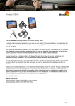
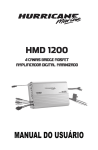
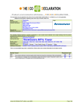
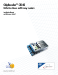
Operating Voltage Window
The operating voltage window defines the maximum voltage that you can apply to each input,
with respect to earth ground, without saturating the probe input circuitry. (See Figure 1.) A
common-mode voltage that exceeds the operating voltage window may produce an erroneous
output waveform even when the differential-mode specification is met.
Offset Voltage Range
Differential-mode
P7513, P7516, P7520
-1.5 V to +2.5 V
Single-Ended and Common-mode
(ground-referenced)
P7513, P7516
-2.0 V to +4.0 V
P7520
-1.8 V to +3.4 V
The Offset Voltage Control, accessible from the attached oscilloscope user
interface, allows the probe dynamic range to be effectively moved up and down
within the limits of the offset voltage range and the operating voltage window.
When the offset voltage is set to zero volts and the input signal is zero volts
(inputs shorted to ground, not open), the displayed signal should be zero volts.
If a noticeable zero volt offset is present under the above conditions, a Probe
Cal operation should be performed. (See the P7500 Series Probes Quick Start
User Manual).
6
Best Practices
High Performance Oscilloscopes- DPO7000 and DPO/DSA 70000 Series
ESD and Probes
To avoid ESD damage to the probe, always use an antistatic wrist strap and work at a staticapproved workstation when you handle the probe.
Soldering
To prevent damage to the circuit board or circuit board connections due to accidental movement
of the probe and soldered leads, we recommend that you secure the tip to the circuit board using
the adhesive tip tape provided in your accessory kit. You can also use other materials such as
Kapton tape or hot glue. To avoid damage to the tip or the circuit under test, avoid applying
excessive heat from the soldering iron. Use a low wattage, temperature-controlled soldering iron
and appropriately sized soldering iron tip.
Use the following precautions when you solder the tips:
7
•
For best soldering results, use a microscope to examine the quality of the solder joints.
•
Use a low-wattage, temperature-controlled soldering iron and a small mass soldering iron
tip. The soldering iron temperature should be set as low as possible, while still providing
a reliable solder joint.
•
Use SAC305 solder (included with the wire replacement kit) to attach the tip wires to the
circuit under test.
•
When replacing tip wires or axial-lead resistors, solder wick can be used to remove the
excess solder from the probe tip circuit board via holes. Be careful not to overheat the via
and damage the board.
•
The attachment wires should be bent symmetrically to vary the interconnect spacing. Use
care when you solder a tip to a circuit under test to avoid inadvertently desoldering either
the attachment wires or the damping resistor.
•
For optimum performance and signal integrity, keep the lead length between the DUT
(Device Under Test) and the tip as short as possible, and the lead lengths the same
length.
Best Practices
High Performance Oscilloscopes- DPO7000 and DPO/DSA 70000 Series
Maintenance of Probes
The input to the probe body, the part of the probe that connects to the various tips, was designed
with replaceable G3PO RF bullets. These RF bullets are similar in function to SMA barrel
connectors. Since the P7500 Series probes can be used with multiple interchangeable tips, there
is the possibility of wearing out or damaging the input connector. To address this issue, the RF
bullets are user replaceable.
The bullet contacts in the probe body should be replaced every 200 insertion cycles. For medium
use situations, this should be about once a year. Follow these steps to replace the bullets by
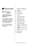
using the removal tool (Tektronix part number: 003-1896-00).
Remove.
1. Squeeze the tool plunger to extend the holder tangs.
2. Insert the tool into the probe body so that the holder tangs surround one of the bullets.
3. Release the plunger to secure the holder tangs on the bullet.
4. Gently pull the tool outward to remove the bullet.
5. Repeat for the other bullet.
CAUTION. If you cannot extract the bullets with the bullet removal tool, use fine needle-nosed
pliers and a magnifying glass or microscope. Be careful not to damage the probe body with the
pliers.
8
Best Practices
High Performance Oscilloscopes- DPO7000 and DPO/DSA 70000 Series
Install. When both bullets have been removed, install new bullets by doing the following:
1. Squeeze the tool plunger to extend the holder tangs.
2. Insert a new bullet into the tool so that the holder tangs surround the bullet.
3. Release the plunger to secure the holder tangs on the bullet.
4. Insert the tool into the probe body and seat the bullet in the recess.
5. Squeeze the tool plunger to release the bullet.
6. Gently pull the tool out of the probe body.
7. Repeat for the other bullet.
8. Test that the bullets are installed correctly by connecting and then removing an accessory
solder tip to the probe head. Inspect the probe head and verify that the bullets remain seated in
the probe head.
9
Best Practices
High Performance Oscilloscopes- DPO7000 and DPO/DSA 70000 Series
03/09 JS/WWW
81W-23825-1