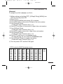
1
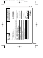
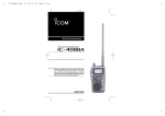
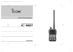
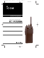
IC-F22SR_4.qxd
06.11.1
1:21 PM
Page 1
New master
INSTRUCTION MANUAL
PMR446 FM TRANSCEIVER
iF22SR
IC-F22SR_4.qxd
06.11.1
1:21 PM
Page 2
New master
FOREWORD
Thank you for purchasing the IC-F22SR PMR446 FM transceiver. This PMR FM transceiver meets the European PMR446
specification. This transceiver is designed for those who require
top-grade quality, performance and outstanding reliability under
the most demanding conditions.
FEATURES
● Free of user-license and applications
● All 8 PMR channels and Auto Scan channel are
available
● 52 convenient CTCSS tone channels
● 83 convenient DTCS tone channels also available
● Rugged construction
● 500 mW (ERP) High output power
Icom, Icom Inc. and the
logo are registered trademarks of Icom Incorporated (Japan) in the United states, the United Kingdom, Germany, France, Spain,
Russia and/or other countries.
i
IC-F22SR_4.qxd
06.11.1
1:21 PM
Page 3
New master
■ 2 types of built-in Code Squelch Systems:
CTCSS; Continuous Tone Coded Squelch System
DTCS; Digital Tone Code Squelch
CTCSS* and DTCS* encoder/decoder are standard, providing
quiet stand-by. Audio (voice) signals are output only when a signal with a matched CTCSS or DTCS tone signal is received—
very helpful for group communications. (pgs. 14, 26)
*Select one of CTCSS or DTCS for your convenience.
■ 2 types of “Ring” function
The “Smart-Ring”* function and the “Call-Ring” function are available for smart and simple station calls providing a telephonestyle ring when called. 16 different ringing tones are available.
(pgs. 19–20)
*“Smart-Ring” function available only when all of your group station use the same CTCSS tone code on the same operating
channel.
SUPPLIED ACCESSORIES
• Belt clip (w/screws)………………………………………………1
• Battery charger …………………………………………………1 set
D Attach the belt clip to the transceiver as illustrated below.
Use the supplied screws only.
ii
IC-F22SR_4.qxd
06.11.1
1:21 PM
Page 4
New master
IMPORTANT
READ ALL INSTRUCTIONS carefully and completely
before using the transceiver.
SAVE THIS INSTRUCTION MANUAL— This instruction manual contains important operating instructions for
the IC-F22SR PMR446 FM transceiver.
CAUTIONS
R WARNING! NEVER hold the transceiver so that the antenna is very close to, or touching exposed parts of the body,
especially the face or eyes, while transmitting. The transceiver
will perform best if the microphone is 5 to 10 cm away from the
lips and the transceiver is vertical.
R WARNING! NEVER operate the transceiver with a
headset or other audio accessories at high volume levels.
DO NOT push the PTT when not actually desiring to transmit.
DO NOT modify the transceiver for any reason.
AVOID using or placing the transceiver in direct sunlight or in
areas with temperatures below –25°C or above +55°C. In an
extreme low temperature environment (around –25°C), the capacity of Alkaline or dry cell batteries may exhaust quickly. In
such case, we recommend to replace the batteries, when the
“Low Battery” warning appears during transmission.
The use of non-Icom battery packs/chargers may impair transceiver performance and invalidate the warranty.
iii
IC-F22SR_4.qxd
06.11.1
1:21 PM
Page 5
New master
TABLE OF CONTENTS
FOREWORD ………………………………………………………………… i
FEATURES ……………………………………………………………… i–ii
SUPPLIED ACCESSORIES ……………………………………………… ii
IMPORTANT ……………………………………………………………… iii
CAUTIONS ………………………………………………………………… iii
TABLE OF CONTENTS …………………………………………………… iv
1 PANEL DESCRIPTION ……………………………………………… 1–3
‘ Switches, controls, keys and connectors ………………………… 1–2
‘ LED indicator …………………………………………………………… 3
2 BATTERY PACKS …………………………………………………… 4–10
‘ Battery pack replacement …………………………………………… 4
‘ Battery cautions ……………………………………………………… 5
‘ Battery charging ……………………………………………………… 6
‘ Charging NOTE ……………………………………………………… 9
‘ Battery case (Option) ………………………………………………… 10
3 BASIC OPERATION ……………………………………………… 11–18
‘ Receiving and transmitting ………………………………………… 11
‘ Setting squelch level ………………………………………………… 13
‘ Auto scan function …………………………………………………… 13
‘ Setting the group code number ………………………………… 14–18
4 RING FUNCTION ………………………………………………… 19–20
‘ Smart-Ring …………………………………………………………… 19
‘ Call-Ring ……………………………………………………………… 19
5 OTHER FUNCTIONS ……………………………………………… 21–23
‘ Monitor audible function …………………………………………… 21
‘ Time-Out Timer ……………………………………………………… 21
‘ Power save function ………………………………………………… 22
‘ Low battery indication ……………………………………………… 22
6 SPECIFICATIONS ……………………………………………………… 23
7 OPTIONS ……………………………………………………………… 24
8 GLOSSARY ………………………………………………………… 25–26
9 CE …………………………………………………………………… 27–28
‘ DECLARATION OF CONFORMITY ……………………………… 28
iv
IC-F22SR_4.qxd
06.11.1
1:21 PM
Page 6
New master
1
PANEL DESCRIPTION
‘ Switches, controls, keys and
connectors
q [CH] selector
w [VOL/ POWER]
e [S-Ring/
C-Ring] key
r [PTT]
t [MONI] key
y TX/RX
Indicator LED
u External
[SP]/[MIC] jack
(see below)
Speaker
MIC
Ext. MIC
SP
MIC
u External
[SP]/[MIC] jack
Antenna
Ext. SP
1
IC-F22SR_4.qxd
06.11.1
1:21 PM
Page 7
New master
PANEL DESCRIPTION
1
q CHANNEL SELECTOR [CH]
• Rotate the selector to select the desired channel number 1 to
15. (pgs. 11, 12)
• Select the Auto Scan channel No.16. (p. 13)
• Select the Call-Ring melody. (p. 19)
w VOLUME/POWER CONTROL [VOL/POWER]
• Rotate the [VOL/POWER] clockwise to turn the power ON/OFF.
A long power ON beep emits when turning the power ON.
• Rotate clockwise to increase and counterclockwise to decrease
the audio volume.
e SMART-RING/CALL-RING KEY [S-Ring/C-Ring]
• Push to send a Smart-Ring call. (p. 19)
• Push and hold to send a Call-Ring. (p. 19)
r PTT SWITCH [PTT]
• Push and hold to transmit; release to receive.
t MONITOR KEY [MONI]
• Push and hold to open the noise/tone squelch.
• Push to turn the tone squelch ON.
y TX/RX INDICATOR LED [LED]
• Lights red while transmitting.
• Lights green while receiving a signal, or squelch is open.
• Lights orange while sending/receiving a Smart-Ring call. (p. 19)
• Indicates the Low-battery condition. (p. 3)
u EXTERNAL SPEAKER AND MICROPHONE JACKS [SP]/[MIC]
• Connects an optional speaker-microphone.
2
IC-F22SR_4.qxd
06.11.1
1:21 PM
Page 8
New master
1
PANEL DESCRIPTION
‘ LED indicator
The TX/RX indicator LED indicates information in several ways as follows;
(Ref.; R=Red, G=Green, O=Orange)
[Brink patterns]
• TX: Turns Red while transmitting a signal.
R
• RX (Busy): Turns Green while receiving a signal.
G
• Smart-Ring: Calling or answering back the Smart-Ring now.
O
O
• Fast/Slow scan: CH scanning or CTCSS FIND is functioning now.
G
G
• Low BATT1: You should charge the battery. (blinks slowly)
R
R
• Low BATT2: You must charge the battery. (blinks fast)
R
R
R
R
• TX low BATT1: Low BATT1 was detected during TX mode.
R
R
• TX low BATT2: Low BATT2 was detected during TX mode.
R
R
R
R
CAUTION:
Low BATT3: If you did not charge the battery after Low BATT2
warning has appeared, the Low BATT3 warning beep emits for 15
sec. then the power turns OFF automatically.
3
IC-F22SR_4.qxd
06.11.1
1:21 PM
Page 9
New master
BATTERY PACKS
2
‘ Battery pack replacement
Before replacing the battery pack, the volume control MUST be rotated fully counterclockwise, until a click is heard, to turn the power
OFF.
• Slide the battery release forward, then pull the battery pack upward with the transceiver facing away from you.
D BATTERY PACKS
Charging period
Battery
pack
Voltage
BP-208N
Battery case for AA
(LR6) × 6 alkaline
Capacity
BC-146
N/A
BP-209N
7.2 V
1100 mAh
BP-210N
7.2 V
1650 mAh 18.5 hrs.
BP-211N
7.4 V
1800 mAh
BP-222N
7.2 V
600 mAh
12 hrs.
BC-144N*1,
Battery life*2
BC-119N or
BC-121N
N/A
—*3
1.5 hrs.
14.5 hrs.
2.0 hrs.
21.5 hrs.
N/A
2.0 hrs.
23 hrs.
6.5 hrs.
1.0 hrs.
8 hrs.
*1
BC-144N cannnot charge Li-Ion battery pack, BP-211N.
*2 Operating period is calculated under the following conditions;
Tx : Rx : standby = 5 : 5 : 90
*3 Operating period depends on the alkaline cells used.
4
IC-F22SR_4.qxd
06.11.1
1:21 PM
Page 10
New master
2
BATTERY PACKS
‘ Battery cautions
• CAUTION! NEVER short the terminals of the battery pack (or
charging terminals of the transceiver). Also, current may flow into
nearby metal objects such as a necklace, so be careful when placing battery packs (or the transceiver) in handbags, etc.
Simply carrying with or placing near metal objects such as a necklace, etc. causes shorting. This will damage not only the battery
pack, but also the transceiver.
• NEVER incinerate used battery packs. Internal battery gas may
cause an explosion.
• NEVER immerse the battery pack in water. If the battery pack becomes wet, be sure to wipe it dry BEFORE attaching it to the
transceiver.
• Clean the battery terminals to avoid rust or miss contact.
• Keep battery contacts clean. It’s a good idea to clean battery terminals once a week.
If your Ni-Cd or Ni-MH battery pack seems to have no capacity
even after being charged, completely discharge it, then fully charge
the battery pack again. If the battery pack still does not retain a
charge (or only very little charge), a new battery pack must be purchased.
5
IC-F22SR_4.qxd
06.11.1
1:21 PM
Page 11
New master
BATTERY PACKS
2
‘ Battery charging
D Regular charging with the BC-146
The supplied* BC-146 provides regular charging of optional battery
pack with/without transceiver.
*Depends on version
D Spacer combination.
Especially when charging the battery with the transceiver;
• Be sure to attach the spacer (Spacer B/C) to the adaptor (Spacer
A) with the orientation as follows.
• Attach the spacer (Spacer B/C) to the adaptor with the orientation
of the stamp “ ” pointing up.
Check orientation
and
Spacer A
Spacer B/C
NOTE: Push the notch carefully
when removing the spacer from
the adaptor.
6
IC-F22SR_4.qxd
06.11.1
1:21 PM
Page 12
New master
2
BATTERY PACKS
D Regular charging with the BC-146 (continued)
• First insert the spacer in to the BC-146, then insert the battery or
the transceiver.
• Be sure to check orientation and the spacer combination.
Avoid overcharging— Batteries must be removed from the
charger to stop charging. Batteries should
not be charged for more than 24 hours.
Turn power OFF
BP-209N, BP-210N
or BP-222N only
AC adaptor
Check
orientation*
Charging indicator
*Viewable stamps of the spacer may differ according to the
spacer combination. See p. 6 for details.
7
IC-F22SR_4.qxd
06.11.1
1:21 PM
Page 13
New master
BATTERY PACKS
2
D Rapid charging with the BC-121N+AD-101
The optional BC-121N allows up to 6 battery packs to be charged
simultaneously. The following are additionally required.
• Six AD-101
• An AC adaptor (may be supplied with the BC-121N depending on
version).
Turn power OFF.
AC adaptor
(purchased
separately)
AD-99N
Charge indicator
(each indicator functions independently)
D Rapid charging with
the BC-144N+AD-99N
The optional BC-144N provides rapid charging of optional battery packs.
The following are additionally required:
• One AD-99N (depends
on version).
• An AC adaptor (may be
supplied with the BC144N depending on version).
Turn power OFF.
Check orientation for correct
charging.
(Insert together
with charging
adaptor.)
BC-144N
8
IC-F22SR_4.qxd
06.11.1
1:21 PM
Page 14
New master
2
BATTERY PACKS
‘ Charging NOTE
Prior to using the transceiver for the first time, the battery pack must
be fully charged for optimum life and operation.
• Recommended temperature range for charging:
+10°C to +40°C.
• Use the supplied charger or optional charger (BC-119N/BC121N/BC-144N for rapid charging, BC-146 for regular charging)
only. NEVER use other manufacturers’ chargers.
The optional BP-209N, BP-210N, BP-211N or BP-222N battery
packs include rechargeable Ni-Cd (Ni-MH: BP-210N, Li-Ion: BP211N) batteries and can be charged approx. 300 times. Charge the
battery pack before first operating the transceiver or when the battery pack becomes exhausted.
If you want to charge the battery pack more than 300 times, the following points should be observed:
• Avoid overcharging— Batteries must be removed from the
charger to stop charging. Batteries should not be charged for
more than 24 hours.
• Use the battery until it becomes almost completely exhausted
under normal conditions.
D Battery pack life
When the operating period becomes extremely short even after
charging the battery pack fully, a new battery pack is needed.
NOTE for the rapid chargers : The charger rapidly charges a
battery pack to a specified level, not a completed level, to prevent
overcharging. Leave the battery pack in the charger for a few
more hours (up to 15 hours; depending on battery condition) after
the LED indicator turns green, to charge the battery completely.
9
IC-F22SR_4.qxd
06.11.1
1:21 PM
Page 15
New master
BATTERY PACKS
2
‘ Battery case (Option)
When using a BP-208N OPTIONAL BATTERY CASE attached to the
transceiver, install 6 AA (LR6) size alkaline batteries as illustrated
below.
D CAUTIONS
• Use ALKALINE batteries only.
• Make sure all battery cells are the same brand, type and capacity.
• Never mix old and new batteries.
Either of the above may cause a fire hazard or damage the
transceiver, if ignored.
• Never incinerate used battery cells since internal battery gas
may cause them to rupture.
• Never expose a detached battery case to water.
If the battery case gets wet, be sure to wipe it dry before using
it.
10
IC-F22SR_4.qxd
06.11.1
1:21 PM
Page 16
New master
3
BASIC OPERATION
‘ Receiving and transmitting
CHARGE the battery pack before first operating the transceiver.
The transceiver has been pre-programmed with all the PMR frequency channels and CTCSS tone codes as a default. The CTCSS
tone number can be changed if required.
Receiving:
q Rotate the [VOL] knob clockwise to
turn the power ON.
w Rotate the [CH selector] to select the
desired operating channel.
• Setting the your group code number
if required. (pgs. 14–16)
e Listen for a transmission and adjust
[VOL] to a comfortable listening level.
• [LED] turns to green, when the received signal contains same CTCSS
or DTCS code number.
• When no transmission is heard,
push and hold [MONI] while adjusting [VOL].
The transceiver is now set to receive desired calls on the selected channel.
[CH selector]
[VOL]
[LED]
[PTT]
[MONI]
*microphone
Transmitting:
Wait for the channel to become clear to avoid interference.
r While pushing and holding [PTT], speak into the microphone at a
normal voice level.
• [LED] turns to red.
t Release [PTT] to return to receive.
IMPORTANT: To maximize the readability of your transmitted signal, pause a few sec. after pushing [PTT], hold the microphone 10
to 15 cm from your mouth and speak at a normal voice level.
11
IC-F22SR_4.qxd
06.11.1
1:21 PM
Page 17
New master
BASIC OPERATION
3
• Frequency channel/CTCSS tone list (default)
Channel
RX/TX Freq. (MHz)*1
CH spacing
Tone (Hz)*2
No.1
446.00625
Narrow
NO
No.2
446.01875
Narrow
NO
No.3
446.03125
Narrow
NO
No.4
446.04375
Narrow
107.2
No.5
446.05625
Narrow
110.9
No.6
446.06875
Narrow
114.8
No.7
446.08125
Narrow
118.8
No.8
446.09375
Narrow
123.0
No.9
446.00625
Narrow
127.3
No.10
446.01875
Narrow
131.8
No.11
446.03125
Narrow
136.5
No.12
446.04375
Narrow
141.3
No.13
446.05625
Narrow
146.2
No.14
446.06875
Narrow
151.4
No.15
446.08125
Narrow
156.7
No.16
Auto Scan
------
------
*1 All operating channel frequencies are fixed.
*2 CTCSS tone frequencies can be programmed by you. You can use
DTCS (Digital Tone Code Squelch) instead of CTCSS. (p. 17)
12
IC-F22SR_4.qxd
06.11.1
1:21 PM
Page 18
New master
3
BASIC OPERATION
‘ Setting squelch level
The squelch circuit mutes the received audio signal depending on
the signal strength.
q While pushing and holding
[PTT] and [MONI], turn the
transceiver’s power ON to enter
the squelch adjustment mode.
w Push [S-Ring/C-Ring] to increase the squelch level (tight
squelch) or [MONI] to decrease
the squelch level (loose
squelch).
• Squelch level will be fixed
after 1 sec.
[S-Ring/
C-Ring]
[PTT]
[MONI]
D Open the squelch
• Pushing and holding [MONI] cancels the squelch function. You
can receive any signals on a channel.
• Push [MONI] to turn ON the tone squelch function again.
‘ Auto Scan function
Auto scan function proceeds in sequence from lower channel to
higher channel numbers. Scanning searches for signals automatically and makes it easier to locate new stations for contact or listening purposes.
q Rotate the [CH] select knob to CH 16.
w Scan starts automatically.
• TX/RX indicator LED blinks green slowly.
• When receiving a signal, scan pauses until the signal disappears.
13
IC-F22SR_4.qxd
06.11.1
1:21 PM
Page 19
New master
BASIC OPERATION
3
‘ Setting the group code number
D USING THE CTCSS TONE CODE
The transceiver is equipped with 52 CTCSS tones. (See next page)
CTCSS operation provides communication with silent standby since
you will only receive calls from group members using the same
CTCSS tone.
You can assign a different tone to CH 1 to CH 15 independently.
q While pushing and holding [PTT], [S-Ring/C-Ring], [MONI], turn
[VOL] to turn the power ON.
w Select the desired CH 1 to CH 15 that you want to assign the
CTCSS tone frequency to.
e Push and hold [S-Ring/C-Ring] until a beep (Pi) is emitted.
r Push [PTT] the necessary number of times to choose the 10 digit
of the desired code from the channel list.
t Push [S-Ring/C-Ring].
• Confirmation beep is emitted. (See next page.)
y Push [PTT] the necessary number of times to choose the 1 digit
of the desired code from the frequency list.
u Push [S-Ring/C-Ring].
i Turn the power OFF, and then ON again.
[Example]
To assign tone code No. 28 as CH1;
q While pushing and holding [PTT], [S-Ring/C-Ring] and [MONI],
turn [VOL] to power ON.
w Select the CH 1, then push and hold [S-Ring/C-Ring] until a beep
(Pi) is emitted.
e Push [PTT] twice to choose the 10 digit of the desired channel.
r Push [S-Ring/C-Ring], then push [PTT] eight times to choose the
1 digit of the desired code.
t Push [S-Ring/C-Ring]. A long beep and 3 short beeps are emitted.
y Turn the power OFF, and then ON again.
14
IC-F22SR_4.qxd
06.11.1
1:21 PM
Page 20
New master
3
BASIC OPERATION
• CTCSS tone code list
: EIA/TIA standard code (Recommended to use these.)
No.
0
1
2
3
4
5
6
7
8
9
10
11
12
13
14
15
No.
16
17
18
19
20
21
22
23
24
25
26
27
28
29
30
31
Freq.
OFF
67.0
69.3*
71.0
71.9
74.4
77.0
79.7
82.5
85.4
88.5
91.5
94.8
97.4
100.0
103.5
Freq.
107.2
110.9
114.8
118.8
123.0
127.3
131.8
136.5
141.3
146.2
151.4
156.7
159.8
162.2
165.5
167.9
No.
32
33
34
35
36
37
38
39
40
41
42
43
44
45
46
47
Freq.
171.3
173.8
177.3
179.9
183.5
186.2
189.9
192.8
196.6
199.5
203.5
206.5
210.7
218.1
225.7
229.1
No.
48
49
50
51
52
Freq.
233.6
241.8
250.3
254.1
270.4
(Unit: Hz)
*Reserved for Smart-Ring function
• Confirmation beep list
Push [PTT]
no
1 (Once)
2 (Twice)
3 (Third)
4 (Fourth)
Confirmation beep
●
●
●●
●●●
●●●●
●; Single beep
; Long beep
15
Push [PTT]
5 (Fifth)
6 (Sixth)
7 (Seventh)
8 (Eighth)
9 (Ninth)
Confirmation beep
●●●●●
●
●●
●●●
●●●●
IC-F22SR_4.qxd
06.11.1
1:21 PM
Page 21
New master
BASIC OPERATION
3
D CTCSS FIND
This transceiver can detect the CTCSS tone frequency in the received signal. By monitoring a signal that is being transmitted from
the other station, you can determine the tone frequency required to
communicate with them.
This function very useful when you are going to communicate with
unknown CTCSS code number stations. ‘CTCSS FIND’ scans all
of the CTCSS codes, then stops when a tone code is detected.
q While pushing and holding [S-Ring/C-Ring], [MONI], turn [VOL]
to turn the power ON.
w Select the desired CH 1 to CH 15 that you want to assign the
CTCSS tone code.
e Push and hold [S-Ring/C-Ring] until a beep (Pi) is emitted.
• ‘CTCSS FIND’ starts to scan the code.
r ‘CTCSS FIND’ stops when the tone code is detected.
t Push [S-Ring/C-Ring] to determine the tone code number.
y Turn the power OFF, and then ON again.
D Turn the squelch function ON/OFF
• Push and hold [MONI] to turn the tone squelch function OFF.
• You can receive any signals on a channel, when you receive
the other group’s signal.
• Push [MONI] to turn ON the tone squelch function again. You
can receive only signals containing the same as your group
code.
16
IC-F22SR_4.qxd
06.11.1
1:21 PM
Page 22
New master
3
BASIC OPERATION
D USING THE DTCS CODE
This transceiver is equipped with 83 DTCS codes. DTCS operation
provides communication with silent standby since you will only receive calls from group members using the same DTCS number.
You can assign different numbers to CH 1 to CH 15 independently.
q While pushing and holding [PTT], [S-Ring/C-Ring] and [MONI],
turn [VOL] to turn the power ON.
w Select the desired CH 1 to CH 15 that you want to assign the
DTCS code to.
e Push and hold [MONI] until a beep (Pi) is emitted.
r Push [PTT] the necessary number of times to choose the 100
digit of the desired code number.
t Push [S-Ring/C-Ring].
• Confirmation beep is emitted. (See p. 15)
y Push [PTT] the necessary number of times to choose the 10 digit
of the desired code number.
u Push [S-Ring/C-Ring].
• Confirmation beep is emitted. (See p. 15)
i Push [PTT] the necessary number of times to choose the 1 digit
of the desired code number.
o Push [S-Ring/C-Ring].
• Confirmation beep is emitted. (See p. 15)
!0 Push [PTT] once more, if you want to use Inverse mode.
!1 Push [S-Ring/C-Ring] to complete the setting.
• Confirmation beep is emitted. (See p. 15)
!2 Turn the power OFF, and then ON again.
17
IC-F22SR_4.qxd
06.11.1
1:21 PM
Page 23
New master
BASIC OPERATION
3
[Example]
To assign code ‘261I (Inverse)’ as CH12;
q While pushing and holding [PTT], [S-Ring/C-Ring], [MONI], turn
[VOL] to turn the power ON.
w Select CH 12.
e Push and hold [MONI] until a beep (Pi) is emitted.
r Push [PTT] twice to choose the 100 digit of the code number.
t Push [S-Ring/C-Ring].
• Confirmation beep is emitted. (See p. 15)
y Push [PTT] six times to choose the 10 digit of the code number.
u Push [S-Ring/C-Ring].
• Confirmation beep is emitted. (See p. 15)
i Push [PTT] once to choose the 1 digit of the code number.
o Push [S-Ring/C-Ring].
• Confirmation beep is emitted. (See p. 15)
!0 Push [PTT] once more, to use Inverse mode.
*You can skip step !0, if you want to use Normal mode.
!1 Push [S-Ring/C-Ring] to complete the setting.
• Confirmation beep is emitted. (See p. 15)
!2 Turn the power OFF, and then ON again.
• DTCS code list (EIA/TIA standard code)
023
025
026
031
032
043
047
051
054
065
071
072
073
074
114
115
116
125
131
132
134
143
152
155
156
162
165
172
174
205
223
226
243
244
245
251
261
263
265
271
306
311
315
331
343
346
351
364
365
371
411
412
413
423
431
432
445
464
465
466
503
506
516
532
546
565
606
612
624
627
631
632
654
662
664
703
712
723
731
732
734
743
754
18
IC-F22SR_4.qxd
06.11.1
1:21 PM
Page 24
New master
4
RING FUNCTION
‘ Smart-Ring
The ring function has an answer back feature. This allows you to
confirm whether or not a call has reached the member of your
group even if the operator is temporarily away from the transceiver.
D Smart-Ring operation (see right)
q Set the same operating channel and CTCSS tone* code for all of
your group transceivers.
w Push [S-Ring/C-Ring] to send the Smart-Ring call.
• When a member of your group station answers your call, then the
transceiver emits beep tones for every 30 sec. and TX/RX indicator
blinks with an orange color.
• Push [MONI] to cancel the Ringer beep and indication.
• When no answer comes back, the transceiver emits short failure
beep tones.
e Push [PTT] to answer the call and to stop the beeps and blinking.
*NOTE: This function is available only when the called station
has use the same CTCSS tone code and the same operating
channels as you.
‘ Call-Ring
Sends the pre-selected ring tone to your group members.
D Select the Call-Ring melody
q While pushing and holding [PTT] and [S-Ring/C-Ring], rotate
[VOL] to turn the power ON.
• A sample melody is emitted.
w Rotate [CH] to select the ringer melody.
• Push [S-Ring/C-Ring] to monitor the selected melody once more.
e Turn the power OFF to determine the melody.
19
IC-F22SR_4.qxd
06.11.1
1:21 PM
Page 25
New master
RINGER FUNCTION
4
• Smart-Ring operation
push [S-Ring/C-Ring]
Piro P
iro
Answer back (automatic)
Piro
Piro
Communication
D Call your group member with Call-Ring melody
➥ Pushing and holding [S-Ring/C-Ring] to sends a ring tone without pushing [PTT].
• The ring tone is emitted while the [S-Ring/C-Ring] key is pressed.
• The same ring tone comes from your group station’s speaker.
20
IC-F22SR_4.qxd
06.11.1
1:21 PM
Page 26
New master
5
OTHER FUNCTIONS
‘ Monitor audible function
The monitor function allows you to open the transceiver’s squelch
manually to check whether a channel is busy or not. The transceiver has 2 conditions for receive standby:
All signals are
received
Only signals containing the proper
tone are received.
Audible condition:
This condition mutes audio ONLY when
no carrier is present. You can receive (or
monitor) any signals on a channel.
• Push and hold the [MONI] switch to cancel the CTCSS or DTCS tone squelch
function.
Any audio mute functions are cancelled
while pushing the [MONI] switch.
Inaudible condition:
This condition mutes ALL signals except
those directed to you. Therefore you
should check a channel’s condition (busy
or not) with the monitor function before
transmitting.
• Push the [MONI] switch momentarily to
select the inaudible condition.
‘ Time-Out Timer
The transceiver has time-out timer function. This function prevents
continuous, extend transmissions. This timer automatically turns a
transmission OFF 3 min. after it starts.
A warning beep emits 10 sec. before the limit is reached.
The end beep emits 5 times to announce the end of the transmission.
21
IC-F22SR_4.qxd
06.11.1
1:21 PM
Page 27
New master
OTHER FUNCTIONS
5
‘ Power save function
The power save function reduces the current drain to conserve battery power.
• The power save function is automatically turned ON when no operation is performed or no signal is received for 5 sec.
‘ Low battery indication
The TX/RX LED indicates 4 levels of the “Low battery” condition as
follows.
If the “Low battery” warning appears during operation, please
charge or replace the battery.
[Brink patterns]
• Low BATT1: You should charge the battery. (blinks slowly)
R
R
• Low BATT2: You must charge the battery. (blinks fast)
R
R
R
R
• TX low BATT1: Low BATT1 was detected during TX mode.
R
R
• TX low BATT2: Low BATT2 was detected during TX mode.
R
R
R
R
In an extreme low temperature surrounding (around –20°C), the
capacity of the battery may exhaust quickly (especially Alkaline
batteries). In such case, we recommend to charge the battery or
replace the batteries, when the “Low Battery” Indication appears
during operation.
22
IC-F22SR_4.qxd
06.11.1
1:21 PM
Page 28
New master
6
SPECIFICATIONS
GENERAL
• Frequency coverage
: 446.00625–446.09375 MHz
• Mode
: F3E (FM)
• No. of operating Ch.
: 8 (simplex)
• Power supply requirement : 7.2 V or BP-222N
• Current drain
: 0.6 A approx.
• Operating temp. range
: –25˚C to +55˚C
• No. of CTCSS freq.
: 38
• Dimensions
: 54(W) × 128(H) × 37(D) mm
(projections not included)
• Weight (approx.)
: 317 g (including BP-222N)
TRANSMITTER
• Output power
• Ext. mic. connector
: Less than 500 mW ERP
: 3-conductor 2.5 (d) mm/2.2 kΩ
RECEIVER
• Sensitivity
• Audio output power
(at 7.2 V DC)
• Ext. speaker connector
: Less than 26.5 dBµV/m
(20 dB SINAD)
: More than 500 mW at 5%
distortion with an 8 Ω load
: 2-conductor 3.5 (d) mm/8 Ω
All stated specifications are subject to change without notice or obligation.
23
IC-F22SR_4.qxd
06.11.1
1:21 PM
Page 29
New master
OPTIONS
7
D BATTERY PACKS/CASE
• BP-208N/BP-209N/BP-210N/BP-211N/BP-222N
BP-208N : Battery case for 6 AA (LR6) alkaline cells
BP-209N : 7.2 V/1100 mAh Ni-Cd battery pack
BP-210N : 7.2 V/1650 mAh Ni-MH battery pack
BP-211N : 7.4 V/1800 mAh Li-Ion battery pack
BP-222N : 7.2 V/600 mAh Ni-Cd battery pack
D RAPID CHARGERS
• BC-119N DESKTOP CHARGER + AD-101 CHARGER ADAPTOR
• BC-121N MULTI-CHARGER + AD-101 CHARGER ADAPTOR (6 pcs.)
• BC-144N DESKTOP CHARGER + BC-145 AC ADAPTOR
D REGULAR CHARGERS
• BC-146 BATTERY CHARGER + BC-147 AC ADAPTOR
D OTHER OPTIONS
• HM-131L SPEAKER-MICROPHONE
• VS-1L VOX/PTT CASE + HS-94/HS-95/HS-97
HS-94: Ear hook type
HS-95: Neck-arm type
HS-97: Throat microphone
• HS-51 HEAD SET
Allows you hands-free operation. Includes PTT and TOT.
• SP-13 EARPHONE
Provides clear receive audio in noisy environments.
• MB-103/MB-86 BELT CLIPS
MB-103 : Same as that supplied with the transceiver.
MB-86 : Swivel belt clip
• MB-96N/MB-96F BELT HANGERS
MB-96N : Swivel belt hanger.
MB-96F : Standard type hanger.
24
IC-F22SR_4.qxd
06.11.1
1:21 PM
Page 30
New master
8
GLOSSARY
✔ What is squelch?
A squelch circuit allows you to mute undesired noise while receiving no signal and emit audio while receiving signals.
This provides quiet standby. The [MONI] key cancels the
squelch setting. This is useful to listen to weak signals that
do not open the squelch.
✔ Talk Range
The IC-F22SR is designed to maximize performance and improve transmission range in the field. However, the single
most important factor in transmit range (talk power) is your
surrounding environment. These radios are “line of sight” radios and as such, transmission range is influenced by the degree to which you can “see” the other communicating party.
Large concrete structures and heavy foliage or transmission
from inside a building or vehicle will reduce your talk power.
• Optimal range : Wide, open areas free of obstructions.
• Medium range : Large buildings or trees blocking your line
of sight.
• Minimum range : Mountainous areas or areas of heavy foliage.
25
IC-F22SR_4.qxd
06.11.1
1:21 PM
Page 31
New master
GLOSSARY
8
✔ What is CTCSS (Continuous Tone Coded Squelch System) ?
CTCSS (Continuous Tone Coded Squelch System) allows
communication with silent stand by. Only signals containing
your group code can open the squelch.
This conveniently eliminates unwanted audio and is useful in
group activities or security related activities where unwanted
output can be a problem. Note that CTCSS group mode is not
private—anyone can receive your calls.
The IC-F22SR is equipped with max. 52 tone codes for CTCSS
use. Selecting a code applies it to all 8 operating channels.
Each push of [PTT] superimposes your group code over your
transmit signal; and, only signals containing the same code can
open your squelch. To temporarily hear all signals (including
noise) push and hold [MONI]. Do not use CTCSS if you want to
be able to hear signals on all channels.
✔ Auto Scan function + Smart-Ring
The Auto Scan function searches for signals automatically
and makes it easier to locate new stations for contact or listening purposes. BUT because the Auto Scan function
checks each operating channel for only a few moments, the
transceiver's response accuracy to Smart-Ring calls is reduced. Use one of CH 1–15 when you and your group are
going to use the Smart-Ring function, otherwise the SmartRing function may fail to answer-back the call.
26
IC-F22SR_4.qxd
06.11.1
1:21 PM
Page 32
New master
9
CE
ABOUT CE
CE Versions of the IC-F22SR which display the
“CE” symbol on the serial number seal, comply
with the essential requirements of the European
Radio and Telecommunication Terminal Directive
1999/5/EC.
This warning symbol indicates that this equipment operates in non-harmonised frequency
bands and/or may be subject to licensing conditions in the country of use. Be sure to check that
you have the correct version of this radio or the
correct programming of this radio, to comply with
national licensing requirement.
27
iC-f22sr
Type-designation:
This compliances is based on conformity with the following harmonised
standards, specifications or documents:
i) EN 60950 (August 1992) + A11: 1997
ii) EN 300 296 (March 2001)
iii) EN 300 279 v1.2.1 (February 1999)
iv)
v)
Signature
T. Maebayashi
General Manager
Authorized representative name
Himmelgeister straße 100
D-40225 Düsseldorf
Icom (Europe) GmbH
Place and date of issue
1:21 PM
Version (where applicable):
UHF PMR TRANSCEIVER
Düsseldorf 31th July 2001
0168
06.11.1
Kind of equipment:
Declare on our sole responsability that this equipment complies with the
essential requirements of the Radio and Telecommunications Terminal
Equipment Directive, 1999/5/EC, and that any applicable Essential Test
Suite measurements have been performed.
1-1-32, Kamiminami, Hirano-ku
Osaka 547-0003, Japan
We Icom Inc. Japan
DECLARATION
OF CONFORMITY
IC-F22SR_4.qxd
Page 33
New master
CE
9
28
IC-F22SR_4.qxd
06.11.1
New master
MEMO
29
1:21 PM
Page 34
IC-F22SR_4.qxd
06.11.1
1:21 PM
Page 35
New master
MEMO
30
IC-F22SR_4.qxd
06.11.1
1:21 PM
Page 36
New master
< Intended Country of Use >
GER
AUT
GBR
IRL
NOR
FRA
NED
BEL
LUX
ESP
POR
ITA
GRE
A-6069D-1EU-r
Printed in Japan
© 2001–2006 Icom Inc.
SWE
DEN
FIN
SUI
1-1-32 Kamiminami, Hirano-ku, Osaka 547-0003, Japan