1
they bring up ‘MS10 self test’ – also MS20 self test tolerance and ‘LA100 self
test’). To alter these, click Options/Tolerance Options and choose the files
you wish to associate with buttons 1 and 2 (see section . An alternative way
of applying tolerance files, useful when trying out several, is to drag-and-drop
them directly onto the results window.
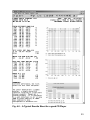
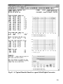
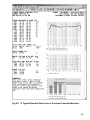
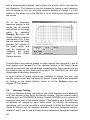
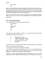
Tolerance files are simple text listings of the form shown below where each
segment character is followed by limits for each of its listed values, separated
by commas. The limits can take a variety of forms such as ±1, or +1-2, or just
-40 (see example below). Leaving out the value before a comma implies a
repeated tolerance, and a question mark means no tolerance to be applied.
Where a line begins with two or more segment letters (eg uvs) the tolerance
list that follows is applied to these segments. Tolerances refer, in turn, to
each line in the list of values that follows a character in square brackets, such
as [u], in the results sheet. Usually these signify the segment that produced
the results, but note that [t] (test level) and [e] (speed error) are ‘notional’
segments only – labels used to permit tolerances to be applied
independently to results that are actually part of another segment (in this
case n or m).
8.10 The Tolerance Definition
Formally, each tolerance string can specify an upper value or a range and a
maximum allowed difference between the two channels, in one of the
following formats:
n
Value must be less than or equal to n
±n
Value must be 0±n
nm
Value must lie between n and m (space or sign separate
n & m)
n±m
Value must be n±m.
Any of these forms can be followed by a difference specifier:
<d
Channels (or registers) must match within difference d
Note that the first form would normally be used for distortion, noise or
crosstalk results, which must normally be below a certain limit (but there is
usually no lower limit - they cannot be too good). The second form (±n)
would normally be used for frequency response, speed error or phase
results, which should ideally be 0, although the third and fourth forms are
often used for frequency response results where different upper and lower
limits can be useful (eg ‘+2-3‘).
n, m and d may be positive or negative, although the + sign is optional. Most
69