1
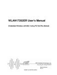
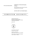
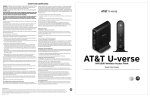
Aphelion Series Aphelion 500AG 802.11a/b/g Multi-functional Outdoor Wireless Access Point User Manual V.05.09.06 August, 2005 802.11a/b/g Intelligent Sequential Outdoor Wireless AP Table of Contents Chapter 1 Warranty and Support ...............................................................1-1 1.1 Warranty .........................................................................................1-1 1.2 Technical Support..........................................................................1-5 Chapter 2 Getting Started...........................................................................2-1 Chapter 3 Hardware Installation ................................................................3-1 3.1 Preparing Installations ..................................................................3-1 3.2 Hardware Description....................................................................3-2 3.3 Outdoor Installations ...................................................................3-10 3.4 Antenna concepts and Installations...........................................3-13 Chapter 4 Wireless Network Topologies...................................................4-1 4.1 Special Daisy Chained Sequential Configuration .......................4-1 4.2 Point to Multi-point configuration ................................................4-1 Chapter 5 Introduction to Aphelion Menus...............................................5-1 Chapter 6 Basic configurations with Aphelion 500..................................6-1 6.1 A look at Aphelion main menu......................................................6-1 6.2 General Configuration ...................................................................6-2 6.3 Advanced Setting...........................................................................6-7 6.4 System Management ...................................................................6-18 6.5 System Monitoring ......................................................................6-23 Chapter 7 Specifications ............................................................................7-1 Chapter 8 Annotations................................................................................8-1 8.1 Wireless Security Concept............................................................8-1 8.2 Firmware Upgrade .........................................................................8-8 Table of Contents I 802.11a/b/g Intelligent Sequential Outdoor Wireless AP Chapter 1 Warranty and Support This Chapter describes Aphelion’s warranty policy and support 1.1 Warranty Subject to the terms and conditions set forth herein, Aphelion Communications Inc, Aphelion provides this Limited Warranty: Only to the person or entity that originally purchased the product from Aphelion or its authorized reseller or distributor. Limited Warranty: Aphelion warrants that the hardware portion of the Aphelion product described below ( Hardware will be free from material defects in workmanship and materials under normal use from the date of original retail purchase of the product, for the period set forth below (Warranty Period) except as otherwise stated herein. Hardware (excluding power supplies and fans): One (1) Year Power supplies and fans: One (1) Year Spare parts and spare kits: Ninety (90) days The customer's sole and exclusive remedy and the entire liability of Aphelion and its suppliers under this Limited Warranty will be, at Aphelion option, to repair or replace the defective Hardware during the Warranty Period at no charge to the original owner or to refund the actual purchase price paid. Any repair or replacement will be rendered by Aphelion at an Authorized Aphelion Service Office. The replacement hardware need not be new or have an identical make, model or part. Aphelion may, at its option, replace the defective Hardware or any part thereof with any reconditioned product that Aphelion reasonably determines is substantially equivalent (or superior) in all material respects to the defective Hardware. Repaired or replacement hardware will be warranted for the remainder of the original Warranty Period or ninety (90) days, whichever is longer, and is subject to the same limitations and exclusions. If a material defect is incapable of correction, or if Aphelion determines that it is not practical to repair or replace the defective Hardware, the actual price paid by the original purchaser for the defective Hardware will be refunded by Aphelion upon return to Aphelion of the defective Hardware. All Hardware or part thereof that is replaced by Aphelion, or for which the purchase price is refunded, shall become the property of Aphelion upon replacement or refund. Warranty and Support 1-1 802.11a/b/g Intelligent Sequential Outdoor Wireless AP Non-Applicability of Warranty: The Limited Warranty provided hereunder for Hardware and Software portions of Aphelion's products will not be applied to and does not cover any refurbished product and any product purchased through the inventory clearance or liquidation sale or other sales in which Aphelion, the sellers, or the liquidators expressly disclaim their warranty obligation pertaining to the product and in that case, the product is being sold "As-Is" without any warranty whatsoever including, without limitation, the Limited Warranty as described herein, notwithstanding anything stated herein to the contrary. Submitting A Claim: The customer shall return the product to the original purchase point based on its return policy. In case the return policy period has expired and the product is within warranty, the customer shall submit a claim to Aphelion as outlined below: The customer must submit with the product as part of the claim a written description of the Hardware defect or Software nonconformance in sufficient detail to allow Aphelion to confirm the same, along with proof of purchase of the product (such as a copy of the dated purchase invoice for the product) if the product is not registered. The customer must obtain a Case ID Number from Aphelion Technical Support at [email protected], who will attempt to assist the customer in resolving any suspected defects with the product. If the product is considered defective, the customer must obtain a Return Material Authorization (RMA) number by completing the RMA form and entering the assigned Case ID Number at https://rma.aphelions.com/. After an RMA number is issued, the defective product must be packaged securely in the original or other suitable shipping package to ensure that it will not be damaged in transit, and the RMA number must be prominently marked on the outside of the package. Do not include any manuals or accessories in the shipping package. Aphelion will only replace the defective portion of the product and will not ship back any accessories. The customer is responsible for all in-bound shipping charges to Aphelion. No Cash on Delivery (COD) is allowed. Products sent COD will either be rejected by Aphelion or become the property of Aphelion. Products shall be fully insured by the customer and ship back to Taiwan. Aphelion will not be held responsible for any packages that are lost in transit to Aphelion. The repaired or replaced packages will be shipped to the customer via DHL Ground or any common carrier selected by Aphelion. Return shipping charges, we will Warranty and Support 1-2 802.11a/b/g Intelligent Sequential Outdoor Wireless AP ship the product to you freight collect. Expedited shipping is available upon request and provided shipping charges are prepaid by the customer. Aphelion may reject or return any product that is not packaged and shipped in strict compliance with the foregoing requirements, or for which an RMA number is not visible from the outside of the package. The product owner agrees to pay Aphelion reasonable handling and return shipping charges for any product that is not packaged and shipped in accordance with the foregoing requirements, or that is determined by Aphelion not to be defective or non-conforming. What Is Not Covered: The Limited Warranty provided herein by Aphelion does not cover: Products that, in Aphelion judgment, have been subjected to abuse, accident, alteration, modification, tampering, negligence, misuse, faulty installation, lack of reasonable care, repair or service in any way that is not contemplated in the documentation for the product, or if the model or serial number has been altered, tampered with, defaced or removed; Initial installation, installation and removal of the product for repair, and shipping costs; Operational adjustments covered in the operating manual for the product, and normal maintenance; Damage that occurs in shipment, due to act of God, failures due to power surge, and cosmetic damage; Any hardware, software, firmware or other products or services provided by anyone other than Aphelion; and Products that have been purchased from inventory clearance or liquidation sales or other sales in which Aphelion, the sellers, or the liquidators expressly disclaim their warranty obligation pertaining to the product. While necessary maintenance or repairs on your Product can be performed by any company, we recommend that you use only an Authorized Aphelion Service Office. Improper or incorrectly performed maintenance or repair voids this Limited Warranty. Disclaimer of Other Warranties: Except for the limited warranty specified herein, the product is provided without any warranty of any kind whatsoever including, without limitation, any warranty of merchantability, fitness for a particular purpose and non-infringement. if any implied warranty cannot be disclaimed in any territory where a product is sold, the duration of such implied warranty shall be limited to the duration of the applicable warranty period set forth above. except as expressly covered under the limited warranty provided herein, the entire risk as to the quality, selection and performance of the product is with the purchaser of the product. Warranty and Support 1-3 802.11a/b/g Intelligent Sequential Outdoor Wireless AP Limitation of Liability: To the maximum extent permitted by law, aphelion is not liable under any contract, negligence, strict liability or other legal or equitable theory for any loss of use of the product, inconvenience or damages of any character, whether direct, special, incidental or consequential (including, but not limited to, damages for loss of goodwill, loss of revenue or profit, work stoppage, computer failure or malfunction, failure of other equipment or computer programs to which aphelion product is connected with, loss of information or data contained in, stored on, or integrated with any product returned to aphelion for warranty service) resulting from the use of the product, relating to warranty service, or arising out of any breach of this limited warranty, even if aphelion has been advised of the possibility of such damages. the sole remedy for a breach of the foregoing limited warranty is repair, replacement or refund of the defective or non-conforming product. the maximum liability of aphelion under this warranty is limited to the purchase price of the product covered by the warranty. The foregoing express written warranties and remedies are exclusive and are in lieu of any other warranties or remedies, express, implied or statutory. Governing Law: This Limited Warranty shall be governed by the laws of the Taiwan. Some countries do not allow exclusion or limitation of incidental or consequential damages, or limitations on how long an implied warranty lasts, so the foregoing limitations and exclusions may not apply. This Limited Warranty provides specific legal rights and you may also have other rights which vary from state to state. Trademarks: Aphelion is a registered trademark of Aphelion Communications Inc. Other trademarks or registered trademarks are the property of their respective owners. Copyright Statement: No part of this publication or documentation accompanying this product may be reproduced in any form or by any means or used to make any derivative such as translation, transformation, or adaptation without permission from Aphelion Corporation/Aphelion Systems, Inc., as stipulated by the United States Copyright Act of 1976 and any amendments thereto. Contents are subject to change without prior notice. Copyright 2004 by Aphelion Corporation/Aphelion Systems, Inc. All rights reserved. Warranty and Support 1-4 802.11a/b/g Intelligent Sequential Outdoor Wireless AP For detailed warranty information applicable to products purchased outside the United States, please contact the corresponding local Aphelion office. 1.2 Technical Support Aphelion believes in ONE goal as to achieve total customer satisfaction; for any technical assistance or information assists, please email to [email protected] or where we have professional engineers standing by to assist you. If you are a qualified reseller of Aphelion, you will be getting usernames and passwords for supporting online where you will find many useful applications notes and FAQs to your needs. Please have the following information ready when you contact Aphelion support: 1. Serial number and model name 2. Firmware version in system monitoring menu 3. Application of which you are deploying with Aphelion 500s and network topology Thank you Warranty and Support 1-5 802.11a/b/g Intelligent Sequential Outdoor Wireless AP Chapter 2 Getting Started This chapter describes Aphelion 500 in short for your applications 802.11a/b/g Intelligent Sequential Outdoor Wireless Access Point World First daisy-chained wireless Access points The Aphelion 500AG is an outdoor Intelligent Sequential Wireless Access Point. With its powerful engineering design, the Aphelion 500AG can form daisy chained wireless Hot Zones easily when engaging multiple Aphelion 500AGs together to meet the ever increasing needs of different network applications. With it’s break through technology innovations, the Aphelion 500AG can offer the following benefits to users in terms of Scalability, Range extension, Expansion in network capacity, powerful routing engine, easy installation and simple management. Aphelion 500AG will be the most ideal candidate for users who wish to deliver carrier class wireless services in multiple market segments such as campuses, hospitality, healthcare, warehousing etc. up to wider metropolitan areas. Features in a Glance: Scalable wireless distribution platform z Daisy chained wireless Hot Zones z Reliable performance when deploying multiple nodes in bridged or routed environments. z Bandwidth control module at subscriber level Comprehensive Security Features z 802.1x EAP support (client and server modes) z EAP-MD5, EAP-TLS support and Dynamic WEP keys z Radius client z Hide ESSID z MAC address filtering z z NAT SSH secure telnet Dynamic WAN Interface Assignments z Easy assignments of WAN exit to fit in different network topology z Flexible wireless network distribution system Getting Started 2-1 802.11a/b/g Intelligent Sequential Outdoor Wireless AP Harsh outdoor environments to keep operation z Sturdy water-tight housing z Built-in heater module to facilitate cold regions z PoE module System Management z Firmware upgrade through TFTP, FTP z Interface status display z SNMP v1/v2 Simple Installation and Deployment z Alignment tools for technicians z Deployment tools for RF analysis Getting Started 2-2 802.11a/b/g Intelligent Sequential Outdoor Wireless AP Chapter 3 Hardware Installation This chapter describes the procedures for installing Aphelion 500AG 3.1 Preparing Installations Package Connects 1 2 4 7 Hardware Installation 3 5 8 6 9 10 3-1 802.11a/b/g Intelligent Sequential Outdoor Wireless AP Contents of Package: 1. Aphelion 500AG 802.11a/b/g Outdoor 6. Wall Mounting Kit & Screw Wireless AP 2. PoE Power Injector 7. Mast Mounting Kit & Screw 3. AC Power Cord 8. CD: User Manual 4. 30M MIL-C-5015 IP67 Cat-5 Ethernet 9. Quick Installation Guide Cable 5. 2M MIL-C-5015 IP67 RS-232 Consol Cable 10. Grounding Wire If any of the above items are missing, please contact your reseller. 3.2 Hardware Description The content of the Aphelion 500AG are described below. 1. The outdoor unit The outdoor unit has one antenna port, one data/power port and one console port. The antenna port is N-Type female connector used to connect to the omni-directional antenna or to the RF cable then to the flat panel antenna. The data/power port is used to link to the cable from the power injector. When the outdoor unit and the network/power injector are connected together, the outdoor unit is turned on and initialized if the network/power injector in the indoor is also installed successfully. The console port is only used at the initial setup and is used to connect to the antenna alignment kit. Hardware Installation 3-2 802.11a/b/g Intelligent Sequential Outdoor Wireless AP Front view of Aphelion 500AG Case Spec. 1. L × W × H: 226 × 197 × 79 mm 2. L × W × H: 245 × 197 × 79 mm (including connector) 3. Weight: 1750g 4. Material: aluminums alloy Front view of RF antenna connector RF antenna connector :The major interfaces on the top of Aphelion 500AG is one female N-Type RF antenna connector with special water proof. Front view of Power / Signal connector port & Console port Power / Signal connector port : 8-pin female connector with MIL-C-5015 IP67 water proof Connecting to the indoor interface unit supplying the power and signal. Console port (TBD): 8-pin male connector with MIL-C-5015 IP67 water proof Connecting to the PC for RF diagnostics & troubleshooting Hardware Installation 3-3 802.11a/b/g Intelligent Sequential Outdoor Wireless AP 2. Antenna (Option) There are three kinds of optional antenna used for Aphelion 500AG. A. 12dBi Omni-directional antenna : This antenna is used in the point-to-Multi-points (PTMP) mode. The antenna is connected directly to the outdoor unit. This antenna is need Male to Male N-type RF cable or Male to Male N-type RF connector. B. 18dBi flat panel antenna : This antenna is used in the point-to-point (PTP) mode or PTMP mode. The antenna is connected to the outdoor unit through an Male to Male N-type RF cable. C. 19dBi flat Dish antenna : This antenna is used in the point-to-point (PTP) mode or PTMP mode. The antenna is connected to the outdoor unit through an Male to Male N-type RF cable. The appearance of the antennas is shown below. A. 10.5dBi Omni-directional antenna B. 16dBi flat panel antenna : Hardware Installation 3-4 802.11a/b/g Intelligent Sequential Outdoor Wireless AP C. 19dBi flat Dish antenna : 3. RF cable & Connector The RF cable is used to connect the outdoor unit and the Omni / panel / Dish antenna. The Male to Male N-type CFD 400 type RF cable with 1.5M length is provided. The Male to Male N-type RF Connector is used to connect the outdoor unit and the Omni antenna. The appearance of the RF cable & Connector are shown below. A. RF cable-1.5M Male to Male N-type CFD 400 type RF cable B. Connector- Male to Male N-type RF Connector Hardware Installation 3-5 802.11a/b/g Intelligent Sequential Outdoor Wireless AP 4. RS-232 console cable (2M MIL-C-5015 IP67 RS-232 Consol Cable) The RS-232 cable is used to connect the console port of the outdoor unit and the antenna alignment tools or the workstation. The One (RS-232) console port has black color for setting up initial configuration information, another (RS-232) console port (blue color) for antenna alignment /deployment tools. The appearance of the RS-232 cable is shown below. Water proof hat 5. Cat-5 Ethernet cable with MIL-C-5015 connector (30M MIL-C-5015 IP67 Cat-5 Ethernet Cable) The Cat-5 Ethernet cable with MIL-C-5015 IP67 connector has 30M in length. It is used to provide the path to deliver power for the outdoor unit and the data communication. The appearance is shown below. 6. Grounding wire The grounding wire is used to provide the grounding path for the outdoor unit to minimize the impact of lightening and surge. The physical appearance of the grounding wire is shown below. Hardware Installation 3-6 802.11a/b/g Intelligent Sequential Outdoor Wireless AP 7. Mounting Kit The mounting kit is used to provide a good support for the outdoor unit and the flat panel antenna. Please follow the installation procedure to mount the outdoor unit and the flat panel antenna. The contents of the mounting kit are shown below. A. Wall Mounting Kit B. Mast Mounting Kit Hardware Installation 3-7 802.11a/b/g Intelligent Sequential Outdoor Wireless AP 8. PoE Power Injector The PoE Power Injector is used to combine the data stream and power into one cable. It has three ports. The port named AC IN is for 100~240V power from AC Power via AC Power Cord. The port named Data Input Port isconnected the customer premises equipment (CPE) by Cat-5 cable. The port named Power & Data Output Port is connected to the outdoor unit by the cable described in item 5. The appearance of the network/power injector is shown below. 9. AC Power Cord The AC Power Cord is to supply the 100~240V power for PoE Power Injector. Hardware Installation 3-8 802.11a/b/g Intelligent Sequential Outdoor Wireless AP Connections Antenna Connector: 1 × Reversed Female N-type Connect to Antenna base by Male to Male N-type CFD 400 RF Cable Special Consol Port Connect one end of the 2M MIL-C-5015 IP67 RS-232 console port cable to this port; connect the other end to a Serial Port on a computer that is running a terminal emulation program; connect the another end to a Serial Port on a notebook or PDA that is running Alignment / Deployment tools program for technicians to analysis RF equipments. Note: Use this console connection only if you are configuring the Aphelion 500AG via the console. (Or when you fail to configure the unit through the Web based utility). Special Ethernet Port Connect one end of the 30M MIL-C-5015 IP67 Cat-5 Ethernet Cable into this port; connect the other end into the Power and Data Output Port on Inline Power Injector. Power & Data Output Port Attach one end of the IP67 Cat-5 Ethernet cable to this port; attach the other end to the 30M IP67 Cat-5 Ethernet Port on the Aphelion 500AG. Data Input Port Connect one end of the cross-over Ethernet cable to this port; connect the other end to the Ethernet port on the computer. Hardware Installation 3-9 802.11a/b/g Intelligent Sequential Outdoor Wireless AP 3.3 Outdoor Installations Aphelion 500AG can be mounted on the side of building or mounted on an antenna mast as shown in following: Step 1 To compose the holder of Aphelion 500AG Step 2 Plug the female end of the power cord into the PoE Injector and then plug the male end of the power cord into a power outlet or power strip. The Power LED on the front of the PoE Injector will light up. Step 3 Plug the RJ-45 Ethernet connector, which is from Aphelion 500AG, into the Power & Data Output Port on the front of the PoE Power Injector, when the Access Point receives power over the Ethernet cable, the Access Point will start its boot sequence and the Active LED on the front of the PoE will light up. Hardware Installation 3-10 802.11a/b/g Intelligent Sequential Outdoor Wireless AP Step 4 Run the crossover Ethernet cable from Data Input Port(on the front of the PoE Power Injector)to the Ethernet Port on the PC or notebook. Step 5 Plug the MIL-C-5015 RJ-45 Ethernet cable into the MIL-C-5015 Ethernet port on the back of the access point. Step 6: Attach the RS-232 Cable(Console Port cable) to the Serial Port. Attach the other cable end (with a marked black spot) to the Serial Port on a PC for setting up initial configuration information; another cable end for antenna alignment /deployment tools. Hardware Installation 3-11 802.11a/b/g Intelligent Sequential Outdoor Wireless AP NOTE: This connection is required for setting up initial configuration information. After configuration is completed, this cable may be removed and put on water proof hat until additional configuration is required via the Serial Port. Step 7 Attach the antenna to the antenna connector as shown in following figure. Hardware Installation 3-12 802.11a/b/g Intelligent Sequential Outdoor Wireless AP Special Notice for Waterproofing Installation Most outdoor model problems are caused from the connector connections that loosen due to vibration or other forces,even allowing moisture to penetrate the connector will seriously affect the data & radio single transmit. The following recommendation is used for all outdoor installation to be waterproofed. Step1: Ensure you already fasten all connectors securely together. RF Extend Cable Connection PoE Cable Connection Step2: Tightly warp two layers of self-bonding insulating tape (the tape from a good brand is recommended) forward and backward over the physical connection extending two inches beyond the connectors or beyond the end of heat-shrinkable tubing on the RF Coaxial cable or Omini Antenna connector, and overlapping the tape on each turn. RF Extend Cable and Connector on the Tape for waterproofing PoE Cable and Connector on the Tape for waterproofing Hardware Installation 3-13 802.11a/b/g Intelligent Sequential Outdoor Wireless AP 3.4 Antenna concepts and Installations RF Path Loss and Transmission Distance Calculations Explanation of Terms Before getting to the nuts and bolts of designing a link, some fundamental terms and concepts need to be reviewed. Transmit Power The transmit power is the RF power coming out of the antenna port of a transmitter. It is measured in dBm, Watts or milliWatts and does not include the signal loss of the coax cable or the gain of the antenna. Receiver Sensitivity Receiver sensitivity is the weakest RF signal level (usually measured in negative dBm) that a radio needs receive in order to demodulate and decode a packet of data without errors. Antenna Gain Antenna gain is the ratio of how much an antenna boosts the RF signal over a specified low-gain radiator. Antennas achieve gain simply by focusing RF energy. EIRP EIRP (Equivalent Isotropically Radiated Power) is the power actually radiated by the antenna element. EIRP takes into account the gain of the antenna. Hardware Installation 3-14 802.11a/b/g Intelligent Sequential Outdoor Wireless AP EIRP (Effective Isotropically Radiated Power) (dBm) performance of transmitting system = Total Output Power of device – Cable Loss + Antenna Gain Free Space Loss As signals spread out from a radiating source, the energy is spread out over a larger surface area. As this occurs, the strength of that signal gets weaker. Free space loss (FSL), measured in dB, specifies how much the signal has weakened over a given distance. Hardware Installation 3-15 802.11a/b/g Intelligent Sequential Outdoor Wireless AP Take into calculations System Gain (dBm) Total gain of radio without antenna/cable System Gain = Tx power – Rx Sensitivity Free Space Loss (FSL) FSPL(dB) = Transmit Power + Gain of the Transmit Antenna + Gain of the Receive Antenna –Receiver Sensitivity = 32.4 + 20Log10F(MHz) + 20Log10D(km) = 36.4 + 20Log10F(MHz) + 20Log10D(mile) = 92.4 + 20Log10F(GHz) + 20Log10D(km) = 96.4 + 20Log10F(GHz) + 20Log10D(mile) ( F : Radio Frequency D : Distance between Transmitter and Receiver) Fade Margin (dB) Fade Margin is“extra” signal power added to ensure the link working Fade Margin = System Gain + Antenna Gain – FSPL – Cable Loss When the calculation of Fade Margin is equal to zero, it means the ultimate connection between the transmitting and receiving system. The more the data of Fade Margin above zero means that the signal is stronger for connection. Otherwise, the connection will be fail if the data of Fade Margin is lower than zero. Hardware Installation 3-16 802.11a/b/g Intelligent Sequential Outdoor Wireless AP Example of Aphelion 500G Here is an example of Aphelion 500G with 12 dBi Gain antenna ( We ignore the cable loss in this case ). As we know the specification of Aphelion 500G below : Transmission power : 14 dBm Receiver sensitivity : -74 dBm Antenna gain : 12 dBi Frequency : 802.11g (2.4GHz) According to the specification, we can calculate the Free Space Loss : FSPL = 14 + (12 +12) – (-74) = 112 We can also estimate the ultimate distance between transmitting and receiving antenna. FSPL = 112 = 32.4 + 20Log10(2400) + 20Log10D(km) D = 3.08 km Hardware Installation 3-17 802.11a/b/g Intelligent Sequential Outdoor Wireless AP Chapter 4 Wireless Network Topologies 4.1 Special Daisy Chained Sequential Configuration For optimal performance, it is suggested to configure the 1st RF module as AP Client and 2nd RF module as Access Point 4.2 Point to Multi-point configuration In the following diagram, Aphelion 500s are configured as daisy chained, point to point and point to multi-points. You will be able to engage multiple Aphelion 500 in a daisy chained topology and yet be maintaining a stable throughput and performance. Application will be range extension, IP camera for environment monitoring, etc.. Wireless Network Topologies 4-1 802.11a/b/g Intelligent Sequential Outdoor Wireless AP Chapter 5 Introduction to Aphelion Menus General Configuration System General Setup (Menu 11) Device Name Description System Operation Mode Set System Date Set System Time Interface Configuration (Menu 12) Interface selection Interface shutdown/enable RIP enable/disable RIP mode IP Address Assignment Operation Mode (Wireless) ESSID (Wireless) Band (Wireless) 802.11a/b/g/bg Channel (Wireless) Tx Power (Wireless) RTS Threshold (Wireless) Frag Threshold (Wireless) Link Rate (Wireless) Distance (Wireless) (Will be available in firmware version 0.973) Assign WAN Interface (Menu 13) Default Gateway Static Routing Configuration (Menu 14) Destination Subnet Mask Gateway IP Metric Introduction to Aphelion Menus 5-1 802.11a/b/g Intelligent Sequential Outdoor Wireless AP Advanced setting System Password (Menu 21) System Password Setting Bandwidth Control (Menu 22) Bandwidth Limit : Enable/Disable General Limit Asymmetrical Bandwidth Limit Default Download Bandwidth Limit Default Upload Bandwidth Limit Symmetrical Bandwidth Limit Total Bandwidth Limit Specific Limit Specific Limit by MAC Address DHCP Configuration (Menu 23) Interface selection DHCP Server : Enabled/Disabled DNS Enabled Primary DNS Server Address Secondary DNS Server Address DHCP Subnet Scope Setup Subnet Mask IP Start IP End Lease(D) Lease(M) NAT Configuration (Menu 24) 1.Port Forwarding NAT(Server Set) 2.Static NAT(one-to-one mapping) Introduction to Aphelion Menus 5-2 802.11a/b/g Intelligent Sequential Outdoor Wireless AP 3.Dynamic NAT(many-to-many mapping) 4.Single Address NAT(PAT) SNMP Configuration (Menu 25) SNMP : Enable/Disable SNMP Version SNMP Read-only Community setup SNMP Read and Write Community setup Trusted Host IP address Wireless Security Setting (Menu 26) Interface selection Hide ESSID : Enable/Disable Encryption Mode : (WEP/EAP_MD5/EAP_TLS) MAC Address Filter MAC Filter : Disable/Enable Filter Policy : Block/Accept RADIUS Server Authentication Server: Server Address Port Shared Secret Accounting Server: Server Address Port Shared Secret Introduction to Aphelion Menus 5-3 802.11a/b/g Intelligent Sequential Outdoor Wireless AP System Management Configuration Management (Menu 31) Configuration : Backup/Restore/Factory Default TFTP Server IP Address TFTP Server Port Number File Name Security File Management (Menu 32) Interface Selection EAP TLS TFTP Server IP Address TFTP Server Port Number User CA RAS Key file Root CA Firmware Upgrade (Menu 33) Transfer Type : TFTP Transfer TFTP Server IP Address TFTP Server Port Number Firmware File Name Transfer Type : FTP Transfer FTP Server IP Address FTP Server Port Number Login UserName Login Password Remote Directory Firmware File Name System reboot (Menu 34) Introduction to Aphelion Menus 5-4 802.11a/b/g Intelligent Sequential Outdoor Wireless AP System Monitoring Interface Link Status (Menu 41) Connecting Client List (Wireless Clients) (Menu 42) System log (Menu 43) 1.Setting System Log SYSLOG file : Enable/Disable Level SYSLOG Server : Enable/Disable Level 2.View System Log System Information (Menu 44) Command Line (Menu 45) alt (Software Alignment tool) arp (Show arp information) date (System time) ping (Ping) reboot (System reboot) tracert (Routing path trace) ver (Show firmware version) Introduction to Aphelion Menus 5-5 802.11a/b/g Intelligent Sequential Outdoor Wireless AP Chapter 6 Basic configurations with Aphelion 500. 6.1 A look at Aphelion main menu The main menu is organized into 4 major functions: 1. General Configuration 2. Advanced Setting 3. System Management 4. System Monitoring Basic Configurations with Aphelion 500 6-1 802.11a/b/g Intelligent Sequential Outdoor Wireless AP 6.2 General Configuration The General configuration consists of four major parts: 11. System General Setup 12. Interface Configuration 13. Assign WAN interface 14. Routing Configuration 6.2.1 System General Setup On this menu you will be able to: 1. Assign name to Aphelion 500 2. description of Purpose 3. Select routing or bridging mode 4. Set system time Basic Configurations with Aphelion 500 6-2 802.11a/b/g Intelligent Sequential Outdoor Wireless AP 6.2.2 Interface Configuration As there are mainly 2 interfaces on the Aphelion 500 On this menu, you will be able to : 1. Select the interface to be configured 2. Enabling and Disabling selected interfaces 3. Address the selected interface as whether to use Static IP address or Dynamic IP address for this interface. 4. RIP (Routing Information Protocol) enable or disable. 5. If RF interface is selected, you can define its wireless parameters here: Operation modes : Access Point or Wireless Station ( Access points or access clients) (For more information, please see the Remark.1 below) ESSID : ChangeMe Band : 802.11a/b/g/bg Channel : auto or define Transmit power : 15 dbm RTS Threshold : 2432 by default Fragment Threshold : 2432 by default Link Rate: Auto or define RF signal transferring distance (Will be available in firmware version 0.973) Remark.1 Introduce two operation mode in menu "12.Interface Configuration". As we know, there are two operation mode of wireless interface in APHELION 500AG, one is "Access Point" and the other is "Wireless Station". When you configure the wireless interface into "Access Point" mode, it means Basic Configurations with Aphelion 500 6-3 802.11a/b/g Intelligent Sequential Outdoor Wireless AP that the wireless interface will be an access point to accept connection requirements from wireless clients, such as wireless notebooks and work stations. Otherwise, if you configure the wireless interface into "Wireless Station" mode, it means that the wireless interface will be a wireless client in your network. The wireless client (just like a wireless notebook) is only looking for the access point which is configured same ESSID exactly. In "Wireless Station" mode, the wireless interface won't accept any connection requirements from other wireless clients. Example 1: Basic Configurations with Aphelion 500 6-4 802.11a/b/g Intelligent Sequential Outdoor Wireless AP Example 2: 6.2.3 Assign WAN Interface Basic Configurations with Aphelion 500 6-5 802.11a/b/g Intelligent Sequential Outdoor Wireless AP This menu allows you to assign your exit for WAN for the Aphelion 500. The Aphelion 500 has 2 interfaces; one Ethernet and one RF interface, you can specify any one to be as WAN; Example, by configuring Ethernet as WAN, you can serve two hotspots simultaneously. 6.2.4 Routing Configuration In this menu you can configure up to 12 rules of Static routes; You will need to input the destination IP address of the next hop gateway together with the associated subnet mask. Basic Configurations with Aphelion 500 6-6 802.11a/b/g Intelligent Sequential Outdoor Wireless AP 6.3 Advanced Setting Under advanced settings, you will be able to configure the following: 21. System Password 22. Bandwidth Control 23. DHCP Configuration 24. NAT Configuration 25. SNMP configuration 26. Wireless Security Setting 6.3.1 System Password In this menu, you will be able to change your admin password. The new password will effect when you login next time. Basic Configurations with Aphelion 500 6-7 802.11a/b/g Intelligent Sequential Outdoor Wireless AP 6.3.2 Bandwidth Control In this menu, you will be able to offer class of services at a subscriber level where segregated bandwidth is where you can define asymmetric and symmetric downstream and upstream data rates for the subscriber or the client devices connecting to Aphelion 500s. There are two bandwidth limit types in Aphelion system (Symmetrical and Asymmetrical) for network administrator to manage the bandwidth of client connections. Once the bandwidth limit is enabled, the limitation will be applied to every client connection. In Symmetrical bandwidth limit type, network administrator can be able to limit Basic Configurations with Aphelion 500 6-8 802.11a/b/g Intelligent Sequential Outdoor Wireless AP consolidated download and upload rate of each single client connection. In Asymmetrical bandwidth limit type, network administrator can be able to limit download and upload rate of client connections specifically. For specific client connection, Aphelion system provides a specific table for network administrator to limit bandwidth of individual client by MAC address. Once the client MAC address is set in MAC table, the general bandwidth limit rule will not take effect in specific MAC address connection but particular bandwidth limit rule. Basic Configurations with Aphelion 500 6-9 802.11a/b/g Intelligent Sequential Outdoor Wireless AP 6.3.3 DHCP Configuration In this menu you will be able to define the scope of DHCP client pool as corresponding to the selected interface and subnet defined. Lease (D) is duration and Lease (M) is maximum. In routing mode configuration, each interface (including Ethernet and Wireless) can be the gateway of its own subnet. It means administrator can have two subnet domains in Aphelion 500AG in routing mode. Basic Configurations with Aphelion 500 6-10 802.11a/b/g Intelligent Sequential Outdoor Wireless AP 6.3.4 NAT Configuration In this menu, there are 4 sub menus as related to NAT configurations. 1. Port forwarding (Server sets) 2. Static NAT (One to One Mapping) 3. Dynamic NAT (Many to Many Mapping) 4. Single Address (NAT/PAT) Basic Configurations with Aphelion 500 6-11 802.11a/b/g Intelligent Sequential Outdoor Wireless AP 6.3.4.1 Port Forwarding In this menu, you will be able to define server sets where internal IP address will be mapped upon according to the TCP or UDP port that you have defined for your applications. 6.3.4.2 Static NAT In this menu, you will be able to map internal private IP address to a global WAN IP address. Basic Configurations with Aphelion 500 6-12 802.11a/b/g Intelligent Sequential Outdoor Wireless AP 6.3.4.3 Dynamic NAT In this menu, you will be able to map a range of internal IP addresses to a range of global IP addresses. 6.3.4.4 Single Address (NAT/PAT) In this menu, you will be able to configure the general NAT, many to one mapping; you will be able to map a range of internal IP addresses to a single global WAN IP address. Basic Configurations with Aphelion 500 6-13 802.11a/b/g Intelligent Sequential Outdoor Wireless AP 6.3.5 SNMP configuration In this menu, you will be able to configure SNMP for simple network management, Aphelion 500 supports SNMP v1, v2 as well as version 3. Aphelion has experience working with ILECs, CLECs, WISPs and MSOs, for customized MIB requirements, please contact [email protected] for assistance. 6.3.6 Wireless Security Setting 6.3.6.1 Encryption Mode Basic Configurations with Aphelion 500 6-14 802.11a/b/g Intelligent Sequential Outdoor Wireless AP In this menu, you will be able to configure wireless security where you will be able to HIDE ESSID and turn on encryption. Aphelion 500 supports 64 bit and 128 bit encryption. WPA1 and WPA2 (TKIP and AES) will be supported in later firmware release, please check www.aphelions.com for firmware updates. In this menu, you will be able to configure EAP_MD5 settings. Basic Configurations with Aphelion 500 6-15 802.11a/b/g Intelligent Sequential Outdoor Wireless AP In this menu, for EAP-TLS, you will be able to upload the digital certificates. 6.3.6.2 MAC Address filtering Basic Configurations with Aphelion 500 6-16 802.11a/b/g Intelligent Sequential Outdoor Wireless AP In this menu, you will be able to configure security setting base on MAC address of the connecting client, either to Accept or block the traffic from the specific MAC. 6.3.6.3 RADIUS Server In this menu, you will be able to configure your radius settings for 802.1x protocol authenticating with the remote radius server for AAA ( Authenticating, Authorization and Accounting. Basic Configurations with Aphelion 500 6-17 802.11a/b/g Intelligent Sequential Outdoor Wireless AP 6.4 System Management Under System Management, you will be able to operate the system by following: 31. Configuration Management 32. Security File Management 33. Firmware Upgrade 34. System reboot 6.4.1 Configuration management 6.4.1.1 Back up and Restore Configuration Basic Configurations with Aphelion 500 6-18 802.11a/b/g Intelligent Sequential Outdoor Wireless AP In this menu, you will be able to backup and restore your configurations; in a daisy chained sequential configurations using Aphelion 500s in a chain, it is recommended that you backup all configurations before uploading firmware. You may name your configuration file in any ways you like. 6.4.1.2 Factory Default loading You will be able to reset back to factory default from this menu. Basic Configurations with Aphelion 500 6-19 802.11a/b/g Intelligent Sequential Outdoor Wireless AP 6.4.2 Security File Management For running EAP_TLS secure connection, network administrators may need to able to upload User Certificate, Root Certificate and RSA Key file to the system. In this menu, system allowed administrators to upload these Certificate files through TFTP server to the access point. (For learning more about wireless security, please refer to Annotations “Wireless Security Concept” in the end of this document.) Basic Configurations with Aphelion 500 6-20 802.11a/b/g Intelligent Sequential Outdoor Wireless AP 6.4.3 Firmware Upgrade In this menu, you will be able to upload new released firmware from TFTP or FTP server. For upgrading firmware from FTP server, you may need to enter the Username and Password for login FTP server. During the upgrade, you will see the upgrading rate of progress show on the page by percentage. To prevent unexpected fail of system, please do not shutdown the system during the upgrade. After the upgrade, system will automatically reboot. New firmware will take effect after system reboot. Basic Configurations with Aphelion 500 6-21 802.11a/b/g Intelligent Sequential Outdoor Wireless AP 6.4.4 System Reboot By selecting menu “34.System reboot”, administrator can be able to reboot the system. Systems will pop-up a confirming dialogue to confirm the reboot requirement. Basic Configurations with Aphelion 500 6-22 802.11a/b/g Intelligent Sequential Outdoor Wireless AP 6.5 System Monitoring In System Monitoring, administrators can monitor the system information through following: 41. Interface Link Status 42. Connecting Client List (Wireless Clients) 43. System log 44. System Information 45. Command Line 6.5.1 Interface Link Status In this menu, administrators can monitor the real-time information of all interfaces of Aphelion 500AG. It will include System Uptime, System Temperature, Tx rate, Rx rate and Noise Level, Data Link Rate, Signal Level in wireless interfaces. (Notice : The Data Rate, Signal Level and Link Quality will show on the screen only when wireless interface is configured as Wireless Station type.) Basic Configurations with Aphelion 500 6-23 802.11a/b/g Intelligent Sequential Outdoor Wireless AP 6.5.2 Connecting Client List In this menu, administrators can monitor all the client connections form wireless interfaces. The connections will show by listing MAC address in this table. 6.5.3 System Log Basic Configurations with Aphelion 500 6-24 802.11a/b/g Intelligent Sequential Outdoor Wireless AP In Aphelion System, system provides seven system log levels (Level1=DEBUG Level2=EMERGENCY Level3=ALERT Level4=CRITICAL Level5=ERROR Level8=WARNING Level7=NOTICE Level8=INFO) for network administrators to adjust the system log level flexibly. Through setting Syslog server IP address, all the system log will send back to the specific log server for centralizing monitoring all the Aphelion devices in the network. 6.5.4 System Information In this menu, administrators can summarize all the configuration and hardware information of the unit. Basic Configurations with Aphelion 500 6-25 802.11a/b/g Intelligent Sequential Outdoor Wireless AP 6.5.5 Command Line In this menu, Aphelion System provides few command for network administrators doing the debug when manage. alt Software Alignment tool, by applying this command, system will show the real-time "Link Quality", "RSSI"(Receive Signal Strength Indication)" and "Noise Level" continually. To stop the Software Alignment tool command, please press "Ctrl"+C on your keyboard. (Notice : Software Alignment tool is only available when wireless interface is configured as "Wireless Station" mode. To have stable wireless connection, we strongly recommend that "Link Quality" should higher than 30% and "RSSI" should higher than -70dbm) arp Show ARP information of the system. date Show System time. ping Ping the remote host IP address from system. reboot Basic Configurations with Aphelion 500 6-26 802.11a/b/g Intelligent Sequential Outdoor Wireless AP Reboot the system. tracert Trace the remote destination IP address to check the routing path. ver To check the system firmware version Basic Configurations with Aphelion 500 6-27 802.11a/b/g Intelligent Sequential Outdoor Wireless AP Chapter 7 Specifications Wireless IEEE802.11a IEEE802.11b IEEE802.11g IEEE802.11b/g Ethernet IEEE802.3 IEEE802.3u IEEE802.3af Ethernet 1×10/100 Base-T RJ-45 Power over Ethernet(PoE) Standard support Wireless Memory Ethernet System Setting Antenna Connector: 1 × Reversed Female N-type SDRAM 32Mbyte Flash 8Mbyte Max. Bandwidth Standard Full Duplex: 200Mbps (for 100BASETX), 20Mbps (for 10BaseT) Half Duplex: 100Mbps (for 100BaseTX), 10Mbps (for 10BaseT) AP / AP Client / Router / Bridge USA: 2.400 – 2.483GHz, 5.15 ~ 5.35Ghz, 5.725 ~ 5.825Ghz Europe: 2.400 – 2.483GHz, 5.15~ 5.35Ghz, 5.47 ~ 5.725Ghz Frequency Range Japan: 2.400 – 2.483GHz, 4.90 – 5.091GHz, 5.15 – 5.25GHz China: 2.400 – 2.483GHz, 5.725 ~5.85Ghz 802.11b/g DSSS (DBPSK, DQPSK, CCK) Modulation OFDM (BPSK,QPSK, 16-QAM, 64-QAM) Technique 802.11a OFDM(BPSK,QPSK, 16-QAM, 64-QAM) 802.11b/g US/Canada: 11 (1 ~ 11) Major European country: 13 (1 ~ 13) France: 4 (10 ~ 13) Japan: 11b: 14 (1~13 or 14th), 11g: 13 (1 ~ 13) China: 13 (1 ~ 13) Channels Support 802.11a 1). US/Canada:12 non-overlapping channels (5.15 ~ 5.35GHz, 5.725 ~ 5.825GHz) 2). Europe: 19 non-overlapping channel (5.15 ~ 5.35GHz, 5.47 ~ 5.725GHz) 3). Japan: 4 non-overlapping channels (5.15 ~ 5.25GHz) 4). China : 5 non-overlapping channels (5.725 ~ 5.85GHz) Wireless 802.11b/g: 11, 5.5, 2, 1 Mbps, auto-fallback, up to 54 Mbps Transmission Rate 802.11a : 54, 48, 36, 24, 18, 12, 9, 6Mbps, auto-fallback Annotations 7-1 802.11a/b/g Intelligent Sequential Outdoor Wireless AP Output Power Wireless Other Setting 802.11b 18 dBm 802.11g 18dBm @6Mbps 15dBm @54Mbps 802.11a 17dBm @6Mbps 13dBm @54Mbps IEEE 802.11b/g Mode Selection Enable / Disable Broadcast SSID MAC Address Filtering Fixed Channel DHCP Client / Server, Fixed IP NAT Static Routing SNMP v1v2 SSID Support Enable / Disable Broadcast WEP Support 64bit / 128bit / 152bit Data Encryption Authentication type: Open System / Shared Key 802.1x Support 802.1x Client and Server Wireless Security Radius WPA MAC Support MAC Address Filtering Firewall Configuration & Management Software / Firmware Power Physical Dimension Spec. Weight Antenna Regulation US and Compliance Europe System configuration interface: Web-base UI via popular browser (MS IE, Netscape…) Firmware upgrade , Reset to default and configuration backup via Web-based Support Telnet to Configuration DC 48Volt / 0.8A ; AC Adapter 100V~240V Support Power over Ethernet (PoE) L × W × H: 226 × 197 × 79 mm 1700g Reversed N-type (Option) FCC Part 15 Class B & C & E ETS 300 328, ETS 301 489-1&17, ETS 301 893 ,EN 60950 compliant and CE Mark Storage Humidity 0% ~ 95% non-condensing Environment Annotations Support NAT Non Heater:-30~65 ℃ With Heater:-40~65 ℃ Built-in heater module is option. -40℃ ~ 80℃ Operating Temp Spec. Support Radius Client WI-FI Protected Access (EAP, TKIP) WPA/PSK 7-2 802.11a/b/g Intelligent Sequential Outdoor Wireless AP Chapter 8 Annotations 8.1 Wireless Security Concept 1 Security For 802.11 Network 2 Why 802.1X 3 EAP 3.1 EAP Types 4 RADIUS overview 5 How EAP-TLS works with FreeRADIUS and Windows XP Security For 802.11 Network Security for 802.11 networks can be simplified into two main components: authentication and encryption. WEP(Wired Equivalent Privacy) is part of the system security of 802.11, and its goals are to provide confidentiality and data integrity, and to protect access to the network infrastructure by rejecting all non-WEP packets. With 802.11's WEP (Wired Equivalent Privacy), all access points and client radio NICs on a particular wireless LAN must use the same encryption key. Sending stations encrypt the frames with a WEP key before transmission, and the receiving station decrypts it using the same key upon reception. This process reduces the risk of someone eavesdropping the transmission and gaining access to the information that the frames are carrying. Why 802.1X The major problem with the 802.11 standard is that the keys are cumbersome to change. If you don't update the WEP keys often, an unauthorized person with a sniffing tool, such as AirSnort or WEPcrack, can monitor your network and decode the encrypted messages. In order to use different keys, you must manually configure each access point and radio NIC with new common keys. But the job of renewing keys on larger networks can be a monumental task. IEEE 802.1x standard helps authenticate and secure wireless LANs. The use of IEEE 802.1X offers an effective framework for authenticating and Annotations 8-1 802.11a/b/g Intelligent Sequential Outdoor Wireless AP controlling user traffic to a protected network, as well as dynamically varying encryption keys. 802.1X ties a protocol called EAP (Extensible Authentication Protocol) to both the wired and wireless LAN media and supports multiple authentication methods, such as token cards, Kerberos, one-time passwords, certificates, and public key authentication. It's important to note that 802.1X doesn't provide the actual authentication mechanisms. When utilizing 802.1X, you need to choose an EAP type, such as Transport Layer Security (EAP-TLS) or EAP Tunneled Transport Layer Security (EAP-TTLS), which defines how the authentication takes place. There are many EAP types, so we'll leave details on EAP types to a future tutorial. The important part to know at this point is that the software supporting the specific EAP type resides on the authentication server and within the operating system or application software on the client devices. The access point acts as a "pass through" for 802.1X messages, which means that you can specify any EAP type without needing to upgrade an 802.1X-compliant access point. As a result, you can update the EAP authentication type as newer types become available and your requirements for security change. Enterprise Network Access Point (Authenticator) Station (Supplicant) RADIUS server (Authentication server) EAP 802.1X uses the Extensible Authentication Protocol (EAP) to relay port access requests between LAN stations ("supplicants"), Ethernet switches or wireless access points ("authenticators"), and RADIUS servers ("authentication servers"). The EAP protocol can support multiple authentication mechanisms without having to pre-negotiate a particular one. Annotations 8-2 802.11a/b/g Intelligent Sequential Outdoor Wireless AP EAP Types Different types of EAP have been defined to support authentication methods and associated network security policies. Here are few widely-deployed EAP types below: EAP-MD5 EAP-Message Digest 5 Challenge Handshake Authentication Protocol (EAP-MD5 CHAP) is a required EAP type that uses the same challenge handshake protocol as PPP-based CHAP, but the challenges and responses are sent as EAP messages. EAP-MD5 CHAP is described in RFC 2284. A typical use for EAP-MD5 CHAP is to authenticate the credentials of remote access clients by using user name and password security systems. You can also use EAP-MD5 CHAP to test EAP interoperability. LEAP (Cisco's Lightweight EAP) Cisco LEAP is a mutual authentication algorithm that supports dynamic derivation of session keys. With Cisco LEAP, mutual authentication relies on a shared secret, the user's logon password—which is known by the client and the network, and is used to respond to challenges between the user and the Remote Authentication Dial-In User Service (RADIUS) server As with most password-based authentication algorithms, Cisco LEAP is vulnerable to dictionary attacks. EAP-TLS (EAP with Transport Layer Security) Transport Level Security (TLS) provides mutual authentication, integrity-protected negotiation, and key exchange between two endpoints. Therefore, EAP-TLS, which includes support for fragmentation and reassembly, provides for these TLS mechanisms within EAP. Windows CE .NET supports EAP-TLS. EAP-TTLS (EAP with Tunneled TLS) In EAP-TTLS, only a Radius Server needs to acquire a Digital Certificate, but a Wireless Station needs to import the certificate of CA (Certificate Authority) so that it can verify the received certificate . The RADIUS server sends it's certificate for stations's verification. And a secure tunnel will be also created at this stage. The station then sends it's user name, password via the secure tunnel. After authentication, both ends begin with Dynamic Key exchanging as in EAP-TLS. Annotations 8-3 802.11a/b/g Intelligent Sequential Outdoor Wireless AP PEAP (Protected EAP) PEAP is an EAP extension for Windows CE .NET that enhances the security of the authentication phase. PEAP provides the security framework for mutual authentication between an EAP client and an EAP server. PEAP is not as secure as Transport Level Security (TLS), but has the advantage of being able to use username/password authentication instead of client certificate authentication. RADIUS overview The Remote Authentication Dial-In User Service (RADIUS) is an Internet draft standard protocol.( See RFCs 2138 and 2139 for more information on RADIUS.) RADIUS is always connected with all kinds of Network Access Server (NAS), such as router, switche, RAS, and all kinds of NAS possible to take responsibility for authentication, authorization, and accounting in telecommunication networks. In large networks, security information can be scattered throughout the network on different devices. RADIUS allows user information to be stored on one host, minimizing the risk of security loopholes. All authentication and access to network services is managed by the host functioning as the RADIUS server. The RADIUS messages which are sent between RADIUS server and RADIUS client are defined by RFCs 2865 and 2866 as follow types: Access-Request A message sent from an access client to an access server in order to request authentication and authorization for a network access connection attempt. Access-accept A message sent from an access server to an access client to response the access-request message which informs the RADIUS client that the connection attempt is authenticated and authorized. Access-reject A message sent from an access server to an access client to response the access-request message which informs the RADIUS client that the connection attempt is not authenticated or authorized. Annotations 8-4 802.11a/b/g Intelligent Sequential Outdoor Wireless AP Access-challenge A message sent by a RADIUS client to specify accounting information for a connection that was accepted. Accounting-Request A message sent by a RADIUS client to specify accounting information for a connection that was accepted. Accounting-Response A message sent by access server to acknowledge the successful receipt and processing of the Accounting-Request message RADIUS messages are sent as User Datagram Protocol (UDP) messages. UDP port 1812 is used for RADIUS authentication messages and UDP port 1813 is used for RADIUS accounting messages. How EAP-TLS works with FreeRADIUS and Windows XP EAP-TLS authentication is based on 802.1x/EAP architecture. Components involved in the 802.1x/EAP authentication process are: supplicant (the wireless station), the authenticator (the access point), and the authentication server (back-end RADIUS server). The supplicant and the authentication server must support EAP-TLS authentication. The access point has to support the 802.1x/EAP authentication process. (The access point is not aware of the EAP authentication protocol type.) The fallowing diagram illustrates the overall 802.1x/EAP authentication process with EAP-TLS as the authentication protocol. (Note that LEAP and EAP MD5 also use the same 802.1x/EAP authentication process.) Annotations 8-5 802.11a/b/g Intelligent Sequential Outdoor Wireless AP Initial 802.1X communications begins with an unauthenticated supplicant (wireless station) attempting to connect with an authenticator (802.11 access point). The access point responds by enabling a port for passing only EAP packets from the client to an authentication server located on the wired side of the access point. The access point blocks all other traffic, such as HTTP, DHCP, and POP3 packets, until the access point can verify the client's identity using an authentication server (RADIUS server). Once authenticated, the access point opens the client's port for other types of traffic. To get a better idea of how 802.1X operates, the following are specific interactions that take place among the various 802.1X elements: 1. The client sends an EAP-start message. This begins a series of message exchanges to authenticate the client; think of this as a group of visitors entering the front gate of a theme park and the group's leader (wireless station) asking the gatekeeper (access point) whether they can enter. 2. The access point replies with an EAP-request identity message. In the case of the theme park, the gatekeeper will ask the leader for their name and drivers license. Annotations 8-6 802.11a/b/g Intelligent Sequential Outdoor Wireless AP 3. The client sends an EAP-response packet containing the identity to the authentication server. The leader in our example will provide their name and drivers license, and the gatekeeper forwards this information to the group tour manager (RADIUS server) who determines whether the group has rights to enter the park. 4. The authentication server uses a specific authentication algorithm to verify the client's identity. This could be through the use of digital certificates or other EAP authentication type. In the case of our example, this process simply involves verifying the validity of the leader's drivers' license and ensuring that the picture on the license matches the leader. In our example, we'll assume the leader is authorized. 5. The authentication server will either send an accept or reject message to the access point. So the group tour manager at the theme park tells the gatekeeper to let the group enter. 6. The access point sends an EAP-success packet (or reject packet) to the client. The gatekeeper informs the leader that the group can enter the park. Of course the gatekeeper would not let the group in if the group tour manager had rejected the group's admittance. 7. If the authentication server accepts the client, then the access point will transition the client's port to an authorized state and forward additional traffic. This is similar to the gatekeeper automatically opening the gate to let in only people belonging to the group cleared for entry. The basic 802.1X protocol provides effective authentication regardless of whether you implement 802.11 WEP keys or no encryption at all. Most of major wireless LAN vendors, however, are offering proprietary versions of dynamic key management using 802.1X as a delivery mechanism. If configured to implement dynamic key exchange, the 802.1X authentication server can return session keys to the access point along with the accept message. The access point uses the session keys to build, sign and encrypt an EAP key message that is sent to the client immediately after sending the success message. The client can then use contents of the key message to define applicable encryption keys. In typical 802.1X implementations, the client can Annotations 8-7 802.11a/b/g Intelligent Sequential Outdoor Wireless AP automatically change encryption keys as often as necessary to minimize the possibility of eavesdroppers having enough time to crack the key in current use. 8.2 Firmware Upgrade In order to upgrade firmware, please prepare a TFTP (Trivial File Transfer Protocol) or FTP server first, make it available via the data-in port on the PoE device. NB: This function is also available in the daisy chain (route mode or bridge mode), just replace the Ethernet connection by the daisy chain connection. 1. Configuration of TFTP server: i. The AP device and TFTP server must place in the same net scope (IP and subnet mask). Use the menu “12. Interface Configuration” user menu to set up the Ethernet interface. ii. Precise the file directory for download, this is the path where you keep the firmware file: here we use the path “D:\ApplicationNotes \NewFirmware \500_firmware\0962” as example. Annotations 8-8 802.11a/b/g Intelligent Sequential Outdoor Wireless AP Annotations 8-9 802.11a/b/g Intelligent Sequential Outdoor Wireless AP Upgrade firmware via TFTP server and FTP sever A. TFTP server upgrade Boot the device; enter to the user interface as below, after the password screen: To upgrade the firmware, please select “33. Firmware Upgrade”. iii. iv. v. Choose the Transfer type by pressing the space bar, till the TFTP transfer shows. Move cursor to next field. In the field of TFTP Server IP Address, input the TFTP server IP, in our demonstration, this IP is “192.168.150.100.” Use arrow keys to go to file name field, input the firmware file name in this demonstration, this is “500V0_972_1.img”. Do use the exact filename, respecting the upper and lower case of file name. Annotations 8-10 802.11a/b/g Intelligent Sequential Outdoor Wireless AP vi. vii. Move cursor to the line of “Upgrade new firmware?” press “Y” to confirm and begin the firmware upgrade process. While the firmware has been upgraded after few minutes, system will automatically reboot. If encounter any problem to upgrade firmware with message “Upgrade new firmware fail, Press 'N' to continue ...” shows. In this case, please verify your TFTP configuration, network and check the file name are exact, launch this procedure above again. Annotations 8-11 802.11a/b/g Intelligent Sequential Outdoor Wireless AP B. FTP server upgrade This option is available from the firmware version 0.971, In order to upgrade firmware, please prepare a FTP server first, make it available via the data-in port on the PoE device. i. ii. iii. iv. v. vi. Choose the Transfer type by pressing the space bar, till the FTP transfer shows. Move cursor to next field. In the field of FTP Server IP Address, input the FTP server IP, in our demonstration, this IP is “192.168.150.100.” Use arrow keys to go to file name field, input the firmware file name in this demonstration, this is “500V0_972_1.img”. Do use the exact filename, respecting the upper and lower case of file name. Please input correctly the IP, user name, password and file name. If the firmware file is down to the sub directory in this FTP server, precise its path in the filed of “Remote Directory”, else leave this filed blank. Move cursor to the line of “Upgrade new firmware?” press “Y” to confirm and begin the firmware upgrade process. While the firmware has been upgraded after few minutes, system will automatically reboot. Annotations 8-12