1
Eux 20, Eux 35, Eux 70 AND EUX 100
USER MANUAL
•
t.l
"••-•^
4
Note
This User's Manual refers to an item called a 'TAG' Sensor. This
version of your system may not include this 'TAG' Sensor. Please kindly
disregard all references to this item while reviewing this User's Manual.
You will find the complete User Manual for your system
(installation, maintenance...) on the CD located in the front of
the binder.
Notice
The information in this document is subject to change without notice and should not be construed as a commitment
by Millipore Corporation. Millipore Corporation assumes no responsibility for any errors that might appear in this
document. This manual is believed to be complete and accurate at the time of publication, in no event shall
Millipore Corporation be liable for incidental or consequential damages in connection with or arising from the use of
this manual.
W e manufacture and sell water purification systems designed to produce pure or ultrapure water with specific
characteristics (|aS/cm, T, TOC, CFU/ml, Eu/ml) when it leaves the water purification system provided that the RiOs
Systems are fed with water quality within specifications, and properly maintained as required by the supplier.
i
W e do not warrant these systems for any specific applications. It is up to the end user to determine if the quality of
the water produced by our systems matches his expectations, fits with norms/legal requirements and to bear
responsibility resulting from the usage of the water.
Copyright
©
2004
MILLIPORE
CORPORATION.
PRINTED
IN
FRANCE.
ALL RIGHTS
RESERVED.
THIS BOOK OR PARTS THEREOF MAY NOT BE REPRODUCED IN ANY FORM WITHOUT THE WRITTEN
PERMISSION OF THE PUBLISHERS.
Documentation: PF08836 (Rev. 2, 11/06)
CD-ROM: PF08814 (Rev. 2, 11/06)
Trademarks
Millipore is a registered trademark of Millipore Corporation.
Elix is a registered trademark of Millipore Corporation.
Progard is a trademark of Millipore Corporation.
Q-Gard is a registered trademark of Millipore Corporation.
RoClean is a trademark of Millipore Corporation.
SLO-BLO is a registered trademark of Littlefuse, Inc.
All other trademarks are trademarks of their respective manufacturers.
Millipore's Standard Warranty
Millipore Corporation ("Millipore") warrants its products will meet their applicable published
specifications when used in accordance with their applicable instructions for a period of one year from
shipment of the products. MILLIPORE MAKES N O OTHER WARRANTY, EXPRESSED OR IMPLIED.
THERE IS N O WARRANTY OF MERCHANTABILITY OR FITNESS FOR A PARTICULAR PURPOSE. The
warranty provided herein and the data, specifications and descriptions of Millipore products appearing
in Millipore's published catalogues and product literature may not be altered except by express written
agreement signed by an officer of Millipore. Representations, oral or written, which are inconsistent
with this warranty or such publications are not authorised and if given, should not be relied upon.
In the event of a breach of the foregoing warranty, Millipore's sole obligation shall be to repair or
replace, at its option, the applicable product or part thereof, provided the customer notifies Millipore
promptly of any such breach. If after exercising reasonable efforts, Millipore is unable to repair or
replace the product or part, then Millipore shall refund to the customer all monies paid for such
applicable product or part. MILLIPORE SHALL NOT BE LIABLE FOR CONSEQUENTIAL, INCIDENTAL,
SPECIAL OR A N Y OTHER INDIRECT DAMAGES RESULTING FROM ECONOMIC LOSS OR
PROPERTY DAMAGE SUSTAINED BY ANY CUSTOMER FROM THE USE OF ITS PRODUCTS.
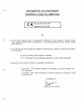
DECLARATION OF CONFORMITY
EUROPEAN UNION EC DIRECTIVES
Directive 89/336/CEE
Directive 73/23/CEE
Elix
• The Elix System mentioned above is manufactured in Millipore SAS - 671 20 Molsheim - FRANCE -facilities
whose quality management system is approved by an accredited registering body to the ISO9001 Quality
System Standards.
•
We certify that these Lab Elix Systems are designed and manufactured in application of the following European
Council directives:
- 89/336/CEE relating to Electromagnetic compatibility
- 73/23/CEE relating to electrical equipment designed for use within certain voltage limits
•
Standards to which conformity is declared as applicable are the following :
EN 61326-1: 1997: Electrical equipment for measurement, control and laboratory use EMC requirements.
EN 61010-1: 2001: Safety requirements for electrical equipment for measurement, control,
and laboratory use.
Guy REYMANN
Quality Assurance Manager
Chapter 1
1-1
Using the Elix System
1
How THE ELIX NORMALLY DELIVERS PRODUCT WATER
1
SDS and Loops
/
A utornatic Method
/
Manual Method
/
Alarm Message Displayed
2
1-2
ELIX WITH A POLISHER, LOOP RESISTIVITY SENSOR OR A10 ADDED
3
1-3
How TO VIEW THE ELIX SYSTEM PERFORMANCE
4
1-4
How TO VIEW SERIAL NUMBERS AND MAINTENANCE INFORMATION FROM THE LCD
7
1-5
Serial Number found on the Elix System Cabinet
7
Serial Number and other information found with the LCD
7
WHAT ARE THE DIFFERENT OPERATING MODES?
Chapter 2
Ordering information
9
10
2-1
CATALOGUE NUMBERS FOR CONSUMABLES
10
2-2
CATALOGUE NUMBERS FOR ACCESSORIES
11
2-3
CATALOGUE NUMBERS FOR ALL ELIX SYSTEMS
11
ir
Chapter 1
1 -1
How
USING THE ELIX SYSTEM
THE ELIX NORMALLY DELIVERS PRODUCT WATER
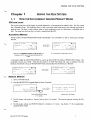
SDS AND LOOPS
The Product Water from an Elix System is normally delivered to a Storage Reservoir (called a SDS). The SDS usually
has a Distribution Pump. The Distribution Pump is used to pressurise stored water and to send it through a network of
pipes (a Loop). The Loop is used to deliver water to various applications such as a dishwasher, a humidifier and so
forth. The water from the Loop that is not used is returned back the SDS.
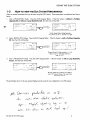
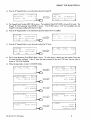
AUTOMATIC METHOD
The Elix System will enter PRODUCTION Mode automatically if it is connected to a SDS or similar type of storage
reservoir.
PRODUCT
PRODUCT
ION
:
T A N K
F U L L
PRODUCT
:
I O C :
2
• 4 0%
3 . 1 M£J T C
p pb DA TA •
S T A N D B Y I)
When the word PRODUCT appears on the 2nd line, the
• 99
1 3 . 1M n
TC
D pb
DATA
STANDBY D
TC = Temperature Compensated to 25 °C
Resistivity and TOC values are measured inside the Elix
System.
A parameter called the TANK LEVEL RESTART is used to go from TANK FULL Mode to PRODUCTION Mode. This
parameter is factory set to 80%. When the Elix System is in TANK FULL Mode and water is withdrawn from the
Reservoir, then the Elix will go to PRODUCTION Mode automatically when the Reservoir is 80% full.
TANK
FULL
199
PRODUCT
: 13.1Mn
TC
TOC
•.
2 i ppb
DATA
STANDBY
PRODUCTION
,80
PRODUCT
: 1 3 . 1M n T C
TOC
:
2 1 ppb
DATA
STANDBY
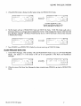
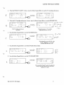
MANUAL METHOD
1.
Start in STANDBY Mode.
2.
Press the PRODUCTION Keypad Button for about 2 seconds.
S T A N D B Y
S E T U P S
M A I N T E N A N C E •
P R O D U C T I O N [)
Press PRODUCTION for about
2 - 3 seconds.
T E S T I N G
P L E A S E
FEED
P R E S S .
W A I T . . .
Lasts for about 16 seconds.
3.
The Elix System will perform a Pressure Test for about 16 seconds. This tests the pressure reaching the Elix
System.
4.
The Elix System will go into RINSING Mode for a minimum of 1 minute. See Section 1 -5 for an explanation
about RINSING Mode.
Elix 20-35-70-100 System
EUX
5.
When RINSING Mode is finished, the Elix System will go into PRODUCTION Mode.
R INS
ING
m
PRODUCT
1 3 . 1 M(!
p p b
4 0%
P RO D U C T
ON
TC
PRODUCT
:
roc
21
D A T A •
S T A N D B Y |)
,40«
1 3 . 1 Mfi
P
pb
T C
D A TA •
S T A N D B Y
I)
If a Polisher Upgrade Kit or a Loop
Resistivity Sensor has been added, then this
LCD may look different. See Section 1 - 2 .
6.
The Elix System will stay in PRODUCTION Mode until TANK FULL Mode. TANK FULL Mode results when a
level sensor device on a storage reservoir indicates that it is full. In this example, the reservoir water level went
from 40% full to 100% full. The Product Water Resistivity shown in TANK FULL Mode is the last value measured
in PRODUCTION Mode.
PRODUCTION
PRODUCT
:
T O C
2 1
.
,401
I 3 . 1MB
P
p b
TC
D A T A •
S T A N D B Y
7.
TANK
FULL
P R O D U C T
:
T D C :
2
• 9 9
1 3 .1MB
p p h
T C
DATA
S T A N D B Y
D
[)
Press STANDBY to exit PRODUCTION Mode if you do not want to go to TANK FULL Mode.
ALARM MESSAGE DISPLAYED
1.
Certain Alarm Messages, when activated, will cause PRODUCTION Mode to stop (i.e. LOW FEED PRESSURE
Mode). See Section 5-1 in the manual on the CD for an explanation of the Alarm and Maintenance
Messages.
PRODUCTION
,401
PRODUCT
: 1 3 . 1 Mfi T C
T O C
2.
:
2 ]
S Y S T E M
f - LO W
S T O P P E D
FEED
, 4 0 1
P R E S S U R E ]
DA T A •
RESUME
•
S T A N D B Y |>
S T A N D B Y
[)
p p b
When the cause of the Alarm Stop Message has been corrected, press RESUME to go back to PRODUCTION
Mode.
Elix 2 0 - 3 5 - 7 0 - 1 0 0 System
1-2
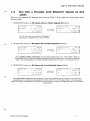
ELIX WITH A POLISHER, LOOP RESISTIVITY SENSOR OR
ADDED
A10
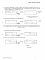
There are a few additional LCD Messages shown when the QGard TL Pack is used or if a Loop Resistivity Sensor
has been added.
1. PRODUCTION Mode for an Elix System without a Polisher Upgrade Kit looks like:
• 4 0 %
R I N S I N G
P R O D U C T
:
3 . 1MQ
IOC
21
p p b
;
T C
D A T A •
P R O D U C T I O N
P R O D U C T
:
I O C
2 1
•.
S T A N D B Y t>
,40
I 3 . IMQ
p p b
TC
D A T A
S T A N D B Y
The TOC value may or may not be shown. This depends if
the Elix System is configured to have an A l 0 TOC Monitor.
2. PRODUCTION Mode for an Elix System with a Polisher Upgrade Kit looks like:
• 4 0
R I N S I N G
P R O D U C T
>
1 O C
2 1
:
I 5 . OMQ
p p b
P R O D U C T I O N
TC
DATA
S T A N D B Y
P R O D U C T
>
TOC
2 1
.
|>
,40
I5 .OMn
ppb
TC
D A T A *
S T A N D B Y |>
W h e n a Polisher is a d d e d to a n Elix System, the existing System Resistivity Sensor is used. When a Polisher is added, the
existing Resistivity Sensor is configured to measure the Resistivity of the Post Q G a r d Polisher Water instead of the post Elix Module
Water. In the example displays above, the Polisher increased the resistivity from 13.1 MQ.cm to > 15.0 MQ.cm (at 25 °C].
3. PRODUCTION Mode for an Elix System with a Loop Resistivity Sensor looks like:
R I N S I N G
• 4 0%
D I ST
3 . 2M(1
roc
p p b
TC
DA T A •
S T A N D B Y I>
P R O D U C T I O N
D I S T
T O C
:
•
20
, 4 0
3 . 2 M O T C
p p b
D A T A *
S T A N D B Y
When DIST is shown on the 2 n d line, then the Resistivity and TOC values are measured from the Loop Water. In the example shown
immediately above, the water in the Loop has a Resistivity of 3.2 MQ.cm (at 25 °C| and a TOC value of 2 9 ppb. In this same example,
pressing DATA will then show the Resistivity and Temperature of the Elix System Product Water (the water filling the storage reservoir that becomes
the Loop Water).
Elix 20-35-70-100 System
•" ,;LIX SYS
1 -3
H O W TO VIEW THE EUX SYSTEM PERFORMANCE
There are several parameters that can be seen using the DATA Button. These parameters are explained and shown
below.
1.
Start in PRODUCTION Mode.
Press the DATA Keypad Button.
If the Elix System is without a Polisher
Upgrade Kit or without a Loop Resistivity Cell, then the LCD will look like:
P R O D U C T I O N
P R O D U C T
:
T O C
2 1
:
I3
IMQ
p pb
,40
TC
D A T A •
P R O D U C T
Q U A L I T Y
P R O D U C T
:
I3 . 1MB
TEMP
:
1 2 °C
T o-e—:
S T A N D B Y |>
n
1- i.. ;..
TC
-> •
The Elix System Product Water Resistivity is
13.2 Mn.cm. at 25 °C. The TOC is 21 ppb.
2.
Start in PRODUCTION Mode. Press the DATA Keypad Button. If the Elix System is with a Polisher Upgrade
Kit, then the LCD will look like:
P R O D U C T I O N
P R O D U C T
>
TOC
21
•
I5 ,0MO
, 4 0 %
P R O D U C T
TC
P R O D U C T
>
1 5 . 0 Mfi
:
12 ° C
DATA
>
TEMP
S T A N D B Y
[)
IOC
ppb
:
Q U A L I T Y
7 \
ppb
TC
-> •
The post QGard TL Polisher resistivity is > 15.0
Mfi.cm at 25 °C. The same water has a
temp, of 12 °C.
3.
Start in PRODUCTION Mode. Press the DATA Keypad Button. If the Elix System is with a Loop Resistivity
Sensor, then the LCD will look like:
P R O D U C T I O N
DIST
T O C
:
•
2 9
,40
DIST
3 . 2 M H T C
DIST
:
TEMP
:
TOC
:
f, p b
DATA
S T A N D B Y
|)
Q U A L I T Y
3.2MB
2 9
p p b
The Loop Water has a resistivity of 3.2 MQ.cm
and a TOC value of 29 ppb. The Loop Water
has a temp, of 19 °C.
The parameters shown in the next several displays are the same for any configuration of an Elix System.
(A
Elix 20-35-70-100 System
O
TC
19 -C
-> •
4.
When the PRODUCT QUALITY is shown, press the Bottom Keypad Button to see the RO Cartridge performance.
PRODUCT
>
TEMP
:
IOC
5.
.
RO
15.0MQ
TC
1 2 °C
2:
ppb
~> •
REJ.
:
P R E S S U R E
R O
FEED
O
M E M B .
EED
E R M E A T E
EJ.
5 3 6 n S
TC
8. V p S
TC
9 8 . 4 %
->•
DATA
1 0 .0
2.1
b ar
b .a r
Feedwater pressure is 2.1 bar and the
applied RO pressure is 10.0 bar.
Press the Bottom Keypad Button to see the FLOWMETER DATA.
P R E S S U R E
R O
F E E D
X
P E R F O R M .
:
P E R M E A T E :
The RO Cartridge performance is
shown here.
6.
M E M B .
FEED
When the RO Cartridge performance is shown, press the Bottom Keypad Button to see the PRESSURE DATA.
R
F
P
R
*
Q U A L I T Y
P R O D U C T
D A T A
1 0 .0
2.1
R O
F LO W
D A T A
P R E S S U R E :
1 0 . 0
b a r
F :2 0 0 l / h R E C : 3 0
b ar
bar
Fdx ?x>
The Feedwater flow rate is 200 LPH. In this
example, an Elix 70_was used and the
calculated System Recovery is 30%.
7.
Press the Bottom Keypad Button to see the Elix Module electrical data.
R O
F LO W D A T A
P R E S S U R E :
1 0 . 0b a r
F :2 0 0 l / h R E C : 5 0 %
8.
E L I X
DA T A
C HAN
I
9 3
C HAN
2
9 7
c
3
I 2 2
HAN
V
Y
V
V
-> •
Press the Bottom Keypad Button to see the CONSUMABLE TIMER.
E L I X
DA TA
C HAN
I :
C HAN
2 :
9 3
V
C HAN
3 :
2 5 0
V
9 3
C O N S U M A B L E
T I M E R S
I
P R O G A R D
R T I M E
: 5 6 D
UV
L A M P
R T I M E
:
2 1 5 D
V
-> •
In this example the Progard TL needs to be replaced in
56 days and the Elix System UV Lamp needs to be
replaced in 215 days.
Elix 20-35-70-100 System
9.
Press the Bottom Keypad Button to see the next display. If the Elix System is configured to have an A l O TOC
Monitor, then the A l O UV Lamp maximum lifetime is shown. In the example shown here, the A l O UV Lamp will
normally be replaced every 365 Calendar Days (365 D).
C O N S U M A B L E
T I M E R S
1
P R O G A R D
R T I M E
:
5 6D
UV
L A M P
R T I M E
:
2 1 5 D
C O N S U M A B L E
T I M E R S
T O C
1AM P R T I M E :
1
-o
... i>
In this example, the Al 0 UV Lamp will need
to be replaced in 100 Days
10. Press the Bottom Keypad Button to see the SETPOINT DATA.
' N S U M A B I. E
'C
LAMP
f; T
S E T P O I N T
M i: f;
DATA
O FF
3 6 5D
«o
P
IODUC1
1 0Mn
TC
2 KMl
TC
D IST
There are 3 Setpoints in the example shown immediately above. The TOC Setpoint is turned off. The Elix System Product Water Resistivity will
turn on a message if its resistivity is < 10.0 MQ.cm. The Loop Resistivity Setpoint is 2 Mn.cm. A message will be displayed if the Loop Water
Resistivity is < 2.0 Mn.cm.
I. Press the Bottom Keypad Button to see DATA PRINT.
S E T P O I N T
D A T A
DATA
TOC
:
O FF
PRODUCT
:
IOMQ
TC
DIST
:
2Mn
T C
P R I N T
C U R R E N T
3 0 D
-> •
V A L U E S •
H I S T O R Y ^
X •
1 2. Press the Bottom Keypad Button to return to PRODUCTION Mode.
D A T A
P R I N T
C U R R E N T
3 0 D
P R O D U C T I O N
V A L U E S
H I S T O R Y ^
X
Elix 20-35-70-100 System
•
-o
PRODUCT
>
TOC
21
.
, 4 5 *
I 5 , OM(1
ppb
TC
DAIA
>
S T A N D B Y |>
1-4
How
TO VIEW SERIAL NUMBERS
INFORMATION FROM THE LCD
AND
MAINTENANCE
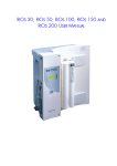
SERIAL NUMBER FOUND O N THE ELIX SYSTEM CABINET
The Serial Number of the Elix System can be found on the left side of the Elix System Cabinet. A Serial Number
sticker is placed just above the Feedwater Tubing Port.
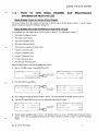
SERIAL NUMBER A N D OTHER INFORMATION FOUND WITH THE LCD
It is possible to view information about your Elix System on the LCD. This information includes:
•
Elix System Catalogue Number
•
Elix System Serial Number
•
Elix System Installation Date
•
Elix System Software Version
•
Elix System Accumulative Production Time
•
Progard TL Serial Number
•
Progard TL Installation Date
•
Progard TL Remaining Time
•
UV Lamp Remaining Time
•
A 1 0 UV Lamp Remaining Time
Follow the steps below to see the information listed above.
•
Start in STANDBY Mode. Press MAINTENANCE.
S T A N D B Y
S E T U P •
M A I N T E N A N C E •
P R O D U C T I O N 0
•
M A I N T E N A N C E
EXCH
P R O G A R D
f XC H G G A RD
DATA >
PACK f
" A C ? r
Press the DATA Keypad Button.
M A I N T E N A N C E
E X C H
P R O G A R D
E XC H O G A RD
D A T A
P A C K
P A C K
E L I X
7 0
C A T .
NB
Z I X 5 5 1 5 0 0
S E R.
NB
F 3NN 12 3 4A
•
The Catalogue Number for the Elix System is shown. The Serial Number for the Elix System is shown.
•
Press the 4 l h Keypad Button to access more information about the Elix System.
ELIX
7 0
C A T .
NB
S E R . NB
IN S T .DA T E
:
0
Z LX S 5 15 0 0
S O F T W A R E
:
VI
F 3N N 12 34A
PRODUCT
ION:
1/09/03
.01 -01
1 6h
-> •
•
The Elix System Installation Date is shown. The Software Version is shown. The Elix System Production Time is
shown. This is the accumulated time that the RO Motor has been powered in order to make RO Permeate
Water.
Elix 20-35-70-100 System
7
EUX SYSTI
•
Press the 41h Keypad Button to see information about the Progard TL.
I N S T . D A T E
:
0
S O F T W A R E
:
V 1 .0 1 •01
ION:
1 6h
P R O D U C T
P R O G A R D
1/09/03
SER.
:
NB
INST.DA.
F 3 N N 8 7 2 5 C
TE:03/09/-03
R.TIME
56D
-> •
•
The Progard Serial Number (SER. NB) is shown. The Installation Date (INST.DATE) is shown (d/m/year). The
Progard TL Pack Remaining Time (R.TIME) is shown. If the R.TIME value is "NA" (not available), then the
Progard TL has been installed within the last 7 days.
Q
Press the 4 lh Keypad Button to see information about the QGard TL if it is installed.
P R O G A R D
:
G G A RD
SER.
: I 3 N N 8 7 2 5 C
SER.
NB
R.TIME
•
:560
3 NN 56 29C
N B
IH 5 T .D A TE
I N S T . D A T E : 0 3 / O 9 / 0 3
->•
Press the 4 th Keypad Button to view information about the UV Lamp.
P R O G A R D
SER.
INSI
NB
.DATE
R.TIME
UV
:
LAMP
T O C
: F 3 N N 8 7 2 S C
LAMP
RTIME
RTIME
2 1 5 D
1 0 0 0
: 0 3 / 0 9 / 0 3
:5 6 D
X •
->•
a
The UV Lamp Remaining Time (RTIME value) is shown. The value shown is based upon the number of hours the
UV Lamp has been powered. If the UV Lamp has been powered for less than 100 hours, then the value is
shown as "NA" (Not Available).
•
Follow the steps below to return to STANDBY Mode.
M A I N T E N A N C E
EXCH
P R O G A R D
EXCH
Q G A S D
M A I N T E N A N C E
EXCH
P R O G A R D
f.: X C H O G A R D
D A T A >
PACK f
PACK!"
M A I N T E N A N C E
p H
C I2
-o
MA
M A I N T E N A N C E
p H
C I2
CLEAN!)
C L E A N
R O
O C
R I N S E D
C tEAN
D A T A
PACK
PACK
M A I N T E N A N C E
INT
C L E A N
C L E A N
ENANCE
RO
R I N S E D
T O C
C I I A N r
M A I N T E N A N C E
[ T-0 I]
D U M P
T A N K D
X •
M A I N T E N A N C E
[ T-0 I]
DUMP
S T A N D B Y
T A N K D
X •
Elix 20-35-70-100 System
-o
SETUP
•
M A I N T E N A N C E
•
P R O D U C T I O N D
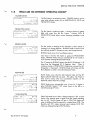
1 -5
WHAT ARE THE DIFFERENT OPERATING MODES?
STANDBY MODE
SETUP
•
M A I N T E N A N C E
•
The Elix System is not producing water. STANDBY Mode is used to
enter other software modes such as MAINTENANCE, SETUP and
PRODUCTION Mode.
D A T A •
The Elix System is producing water. A storage reservoir is getting
filled with water from the Elix System.
Pressing DATA in
PRODUCTION Mode allows various operating parameters to be
S T A N D B Y
P R O D U C T I O N ^
PRODUCTION MODE
PRODUCTION
PRODUCT
>
T O C
:
1 5 .0 Mn
2 1
p p b
,40
TC
S T A N D B Y
0
seen.
RINSING MODE
• 4 0
R I N SI N G
P R O D U C T
1 5 . 0 MO
P p b
TC
DA T A •
STANDBY
The Elix System is diverting the RO Permeate to drain instead of
sending it to a Storage Reservoir. RINSING Mode is used to insure
that only high quality RO Permeate is sent to the Storage Reservoir.
RINSING Mode occurs for a few different reasons.
One reason is that the Elix System is going into PRODUCTION
Mode. RINSING Mode will occur automatically for one minute or
more whenever entering PRODUCTION Mode.
The 2 nd reason for RINSING Mode is that the RO % Rejection is \%
lower than the Memorised RO % Rejection Value.
When 4
continuous minutes of PRODUCTION Mode have occurred, the RO
% Rejection is "memorised". RINSING Mode will continue until the
RO % Rejection is within 0.5% of the Memorised Value.
FLUSH MODE
RO
FLUSH
SETUP
•
M A I N T E N A N C E
•
C A N C E L [>
RO
FLUSH
• 9 9%
P ( O D U C T
1 5 . 0 Mn
1
p p b
TC
DA T A •
FLUSH Mode occurs when the Inlet Solenoid Valve and the RO
Reject Solenoid Valve both are open. This allows Tap Water to
enter and to sweep away any accumulated impurities on the
Feedwater surface of the RO Cartridge.
FLUSH Mode occurs automatically every 6 hours for 5 minutes in
either STANDBY Mode (1 st LCD screen shown on the left) or in
TANK FULL Mode (2nd LCD).
C A NC E LD
TANK FULL MODE
TANK
• 9 9
FULL
P R O D U C T
>
5 .0 M n
TOC
2
p p b
:
T C
D A T A •
S T A N D B Y
Elix 20-35-70-100 System
I)
TANK FULL Mode occurs when a Storage Reservoir is full. A Level
Sensor in the reservoir sends a signal to the Elix System indicating
that it is full. The Elix System will stay in TANK FULL Mode until
water is withdrawn from the reservoir (i.e. emptied about 20%). The
Resistivity and TOC values measured upon entering TANK FULL
Mode are displayed during TANK FULL Mode.
Chapter 2
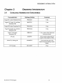
2-1
ORDERING INFORMATION
CATALOGUE NUMBERS FOR CONSUMABLES
Consumable Item
Catalogue Number
Comments
Progard TL1 System Pretreatment Pak
PROGTLOS1
I/box
Progard TL1 System Cl 2 autoClean
Pretreatment Pak
PR0GTLCS1
I/box
Progard TL2 System Pretreatment Pak
PROGTLOS2
I/box
Progard TL2 System Cl 2 autoClean
Pretreatment Pak
PROGTLCS2
I/box
PrePakLl Pre-System
Pretreatment Pak
PRPKOLOS1
1 /box; requires Pack Holder (see
Accessories below)
UV Lamp
ZLXUVLPL1
1 /box (used for replacement UV
Lamp for an Elix System or ASM)
QGard TL1 Polishing Pak
QGARDTL01
1 /box (used only with an Elix
System having the Polishing Option
added)
ATOUVLamp
ZFA10UV01
I/box
Elix 20-35-70-100 System
10
.VIATIOI
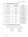
2-2
2-3
CATALOGUE NUMBERS FOR ACCESSORIES
Accessory
Catalogue Number
Comments
RiOs/Elix-L Syst. Wall Bracket
ZD(OWMBKT
W a l l Mounting Bracket for an Elix
System
Wall Bracket PrePak L
WBPRPKL01
Wall Mounting Bracket for external
PrePak L
Water Sensor RiOs/Elix-L
TANKLK001
Water Sensor that connects to an
Elix System
Water Sensor with cable
TANKLK002
Used to add a 2 nd Water Sensor.
RiOs/Elix-L Cleaning Port Kit
ZROOCLNKT
Used to add a Cleaning Port to
the Elix System.
RiOs/Elix-L Q-Gard TL Kit
ZLXQGRDKT
Kit allows an Elix System to use a
Polisher to deionise the Product
Water.
RiOs/Elix-L Resistivity Sensor Kit
ZLXORESKT
Kit allows the measurement of
resistivity in a loop and to be
reported on the Elix System LCD.
Flow Meter Kit RiOs/Elix-L
ZLXFLOWKT
Kit allows an extra Flow Meter to
be added to an Elix System.
System Mounting Cart
ZAFSCART1
Cart which can be used to hold
the Elix System.
Elix-L TOC Upgrade Kit
ZLXOTOCKT
Kit that allows an A l 0 to be
added to an Elix System.
CATALOGUE NUMBERS FOR ALL ELIX SYSTEMS
s
X
0
J:
5 = 230 VAC
020 = ELIX 20
6 = 120 VAC
035 = ELIX 35
7 = 100 VAC
070 = ELIX 70
100 = Euxl00
Elix 20-35-70-100 System
11