1
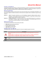
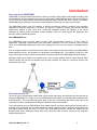
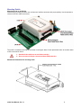
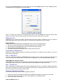
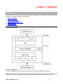
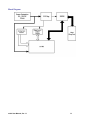
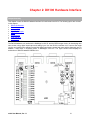
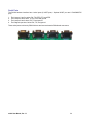
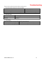
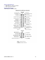
m100 USER MANUAL
Product Version: 1.1
May 2007
Copyright© 2007 m100
m100 User Manual, Product Version: 1.1
Copyright © 2007 MobiApps
All rights reserved.
MobiApps has prepared the information contained herein, solely for the use of employees, agents and its
customers. The information contained in this document is subject to change. Any change that occurs shall be in
accordance with MobiApps control procedure. This document contains proprietary information and is protected
by copyright. Preparing derivative works or providing instruction based on the material is prohibited unless
agreed to in writing by MobiApps.
All information contained herein is believed to be accurate and reliable. MobiApps may make improvement
and/or changes in the product(s) and the program(s) described in this manual at any time and without notice.
Trademarks
All Names, products, and trademarks of other companies used in for publishing the manual are the property of
their respective owners and are acknowledged. MS Word, Windows 2000, are the registered trademarks of
Microsoft Corporation. Acrobat is the registered trademarks of Adobe Corporation.
Important Safety Notices
Carefully observe the safety alert symbols below for dangers, warnings, and cautions. They alert installers and
operators of possible dangers and also give important and necessary information regarding the product.
Technical Support
For assistance or repair of the m100, please contact MobiApps at the following:
Website
Postal Address
m100 User Manual, Ver 1.1
www.mobiapps.com
7315 Wisconsin Ave
Suite 1050E
Bethesda, MD 20814
ii
Table of Contents
Important Safety Notices....................................................... ii
Technical Support ................................................................. ii
Table of Contents................................................................................iii
About this Manual ................................................................................1
Purpose of the Manual..........................................................1
Manual Organization.............................................................1
Reference Document ............................................................1
Symbols used in the Manual.................................................1
Who should read this Manual ...............................................2
Glossary................................................................................2
Introduction ..........................................................................................3
Overview about ORBCOMM.................................................3
Overview about m100 ...........................................................3
General Representation........................................................4
Section – 1: m100.................................................................................5
Chapter 1: Hardware Integration.........................................................6
Overview...............................................................................6
m100 Block Diagram.............................................................6
I/O Pin Interface Specification...............................................8
Interface Connector ..............................................................8
Mounting Details ...................................................................9
General Description of m100 ..............................................10
Power Interface...................................................................11
Antenna Interface................................................................11
Chapter: 2 Software Interface ...........................................................12
System Environment...........................................................12
Diagnostic Port....................................................................13
Commands and Responses................................................13
Host -1 Serial Port...............................................................13
Host - 2 Serial Port..............................................................13
Firmware Upgrade Procedures ...........................................13
Developing Applications......................................................14
Chapter 3: Operation .........................................................................15
System Architecture............................................................15
Device Configuration...........................................................15
Host Vs Diagnostic Port ......................................................16
Sending and Receiving Message........................................16
Low Power Modes ..............................................................16
Satellite Acquisition.............................................................16
Section 2: DK100................................................................................17
Chapter 1: Introduction to DK100 .....................................................18
Overview.............................................................................18
Key Features ......................................................................18
On-board Peripherals..........................................................19
General Precautions ...........................................................19
DK100 PCB ........................................................................19
m100 User Manual, Ver 1.1
iii
Block Diagram ....................................................................20
Chapter 2: DK100 Hardware Interface ..............................................21
DK100 Architecture.............................................................21
Power Supply......................................................................22
Analog Input........................................................................22
Digital Input / Output ...........................................................22
GPIO...................................................................................23
Potentiometer .....................................................................23
m100 Interface ....................................................................23
Serial Ports .........................................................................24
Chapter 3: Setting Up DK100 Evaluation Kit ...................................25
DK100 Evaluation Kit Architecture ......................................25
Connecting the m100 SC to the Hardware Interface Unit ...25
Connecting Host Port to Customer Target Circuitry ............25
Connecting Diagnostic Port to DTE ....................................25
Powering the DK100 Evaluation Kit ....................................25
Troubleshooting.................................................................................26
Appendix.............................................................................................27
Application Interface ...........................................................27
Satellite Communications ...................................................27
Power Specifications...........................................................27
Application Programming....................................................27
Environment........................................................................27
Mechanical..........................................................................27
GPS ....................................................................................27
Antenna Specifications .......................................................28
Standard Pin Diagram.........................................................28
m100 User Manual, Ver 1.1
iv
About this Manual
Purpose of the Manual
This manual describes all the features, functions and interfaces of m100. The manual also covers the hardware
integration, software interface, operations, features of the evaluation kit, and the specifications required for
m100. This manual also provides a list of accessories required with the evaluation kit.
Manual Organization
This manual has two sections. The first section covers the all the details of the m100 Satellite- Data Modem. The
third section explains the DK100 Evaluation Kit. Each section has chapters which are divided into topics for easy
reference.
Section 1:
m100 - This section introduces you to m100 Hardware Integration, Software Interface and the
Operations. These chapters provide you with the information of m100 which covers the block
diagram, firmware details, and system architecture.
Section 2:
DK100 Evaluation Kit - This section introduces you to the DK100 Evaluation Kit. It provides the
key features, connection details, PCB layout, block diagram. This section helps the user to
understand the interfacing between m100 with the application.
Reference Document
The m100 user manual references the following documents:
•
•
•
•
ORBCOMM Serial Interface specification
SDK API programmers guide
m100 Hardware Interface guide
ORBCOMM system overview
Symbols used in the Manual
The symbols shown below are used throughout this manual to highlight important instructions.
Symbol
Description
Warning! If ignored, may cause permanent damage to the development kit or injury to a
person.
Caution! Failure to comply with a caution may result in failure or damage to the device.
Danger! Failure to comply with a danger symbols results in serious injury.
Tip. Information that may be beneficial to the user. Experienced or qualified personnel may choose
to skip.
Provides additional information corresponding to the topic that is being discussed.
m100 User Manual, Ver 1.1
1
Who should read this Manual
Target audience for this manual are listed below:
•
•
•
OEM customers
Programmers and test engineers
System integrators
Glossary
Analog
ASCII
DB9
DC
Diagnostic
Port
Digital
DK 100
DTE
FRC
Globalgram
GPS
Hex
I/O
Modem
OEM
ORBCOMM
PCB
SC
SMTP
VHF
Describes data that can assume a continuous range of values such as current, voltage or
pressure readings. The amplitude of such a signal fluctuates over a continuous range from zero
to the maximum/peak output.
American Standard Code for Information Interchange: A standard developed by ANSI that
defines how computers write and read characters. It consists of 128 characters including letters,
numbers, punctuation and control codes. Each character is represented by a number. It’s used
by most operating systems.
A nine pin physical connector that is common on PCs and a secondary connector specified in
RS-232.
Abbreviation for Direct Current. A movement of electric charge across an arbitrarily defined
surface in one direction only.
Diagnostic port is a port of the modem. The baud rate of this port is fixed (115200). The user
can view the debug statements on the HyperTerminal connected to the Diagnostic port of the
modem.
Describes data that can assume only two values: on or off, 1 or 0, true or false. Also known as
discrete.
DK 100 is a Printed Circuit Board on which m100 transceiver and other electronic devices are
mounted.
Abbreviation for Data Terminal Equipment. Any digital device that transmits and receives data.
Flat Ribbon Cable – This is the cable that connects m100SC and DK 100 Evaluation Kit.
A Globalgram is a basic service element for the SC to send and receive a single, self contained
data packet from a satellite when the satellite does not have access to ORBCOMM gateway.
Abbreviation for Global Positioning System. A worldwide MEO satellite navigational system
formed by 24 satellites orbiting the earth and their corresponding receivers on the earth. The
satellites orbit the earth at approximately 12,000 miles above the surface and make two
complete orbits every 24 hours. The GPS satellites continuously transmit digital radio signals
that contain data on the satellites location and the exact time to the earth-bound receivers.
Hexadecimal. Made up of 16 parts. The hexadecimal numbering system uses the numbers 0 to
9 plus letters A through F to represent the 16 digits.
Input/Output. The flow of data to and from the device. Also referred to the peripherals sending
the data, and the path they use.
Modulator-Demodulator. A modem is a device or program that enables a computer to transmit
data. For example, telephone or cable lines. Computer information is stored digitally, whereas
information transmitted over telephone lines is transmitted in the form of analog waves. A
modem converts between these two forms.
Abbreviation for Original Equipment Manufacturers. OEMs buy products in bulk and customize
them for a particular application.
ORBCOMM uses Low-Earth-Orbit (LEO) satellites to provide cost-effective tracking, monitoring
and messaging capabilities to and from anywhere in the world.
A thin plate on which chips and other electronic components are placed.
Subscriber Communicator. Modems that are configured to the ORBCOMM satellites to send and
receive messages.
Simple Mail Transfer Protocol, a protocol for sending e-mail messages between servers. Most email systems that send mail over the Internet use SMTP to send messages from one server to
another; the messages can then be retrieved with an e-mail client using either POP or IMAP. In
addition, SMTP is generally used to send messages from a mail client to a mail server.
Abbreviation for Very High Frequency. The radio frequency in the range 30 MHz - 300 MHz.
m100 User Manual, Ver 1.1
2
Introduction
Overview about ORBCOMM
ORBCOMM is a wireless telecommunications company providing narrow band two-way digital messaging, data
communications, and geo-positioning services on a global basis. ORBCOMM operates a network consisting of
30 Low Earth Orbit (LEO) satellites and terrestrial gateways deployed around the world. Through this network,
ORBCOMM delivers information to and from virtually anyplace in the world on a nearly real time basis.
The ORBCOMM system uses LEO satellites to provide cost-effective tracking, monitoring and messaging
capabilities to and from anywhere in the world. The system is capable of sending and receiving two-way
alphanumeric packets of data. These short, economical messages increase the efficiency of the remote
operations by making critical information readily available, often from areas beyond the geographic and
economic reach of traditional systems.
How ORBCOMM works
The ORBCOMM system provides global, two-way, data communication services to a wide variety of
applications. Subscriber communicators (SCs) pass data messages to and from Gateway Control Centers
(GCC) over ORBCOMM satellites and GCCs route messages to users over the internet or dedicated delivery
lines.
SCs are a highly versatile communication device which communicates directly with satellites using ORBCOMM's
packet-switched protocol, and supports full transmission acknowledgement. The satellites provide SCs with
system information and serve as the communication link between SCs and the ORBCOMM terrestrial network.
Messaging traffic flows between the satellites and a GCC through tracking stations called Gateway Earth
Stations (GESs) that connect with satellites as they pass overhead. The internet is commonly used for final
transmission to the user.
Overview about m100
The m100 is the next generation satellite data communication transceiver that transmits and receives data by
using the ORBCOMM. The m100 is a low cost ORBCOMM modem based on the Analog Devices Blackfin DSP
and analog ASIC. The m100 OEM transceiver plays a vital role in transmitting and receiving the data for the
customers involved in satellite-based tracking and industrial remote communication.
The m100 operates over the ORBCOMM low orbit satellite network, providing unlimited global coverage with no
blockage. It can significantly improve asset utilization by allowing clients to monitor, track and manage their fixed
and mobile assets around the world. The three chip m100 OEM transceiver includes the Analog Devices
Blackfin® DSP family, MobiApps' Analog ASIC, and a GPS RF down converter, creating a fully integrated
satellite tracking device.
m100 User Manual, Ver 1.1
3
The m100 is a versatile product and users can quickly implement the solutions that are optimized for their
tracking and monitoring applications. The target market of m100 is OEMs and VARS developing fixed site or
mobile tracking / monitoring applications.
General Representation
m100 User Manual, Ver 1.1
4
Section – 1: m100
This section introduces you to the Hardware Integration, Software Interface
and the Operation of m100. Explore the following chapters in this section:
•
•
•
m100 User Manual, Ver 1.1
Chapter 1: Hardware Integration
Chapter 2: Software Interface
Chapter 3: Operation
5
Chapter 1: Hardware Integration
Chapter Summary
This chapter provides the overview of hardware integration of m100 satellite data transceiver. The chapter also
lists the specifications and interfaces required. The chapter covers the following topics:
•
•
•
•
•
•
•
•
Overview
m100 Block Diagram
I/O Pin Interface Specification
Interface Connector
Mounting Details
General Description of m100
Power Interface
Antenna Interface
Overview
The m100 is a small and smart modem which provides geo-positional data through message transmission and
reception via ORBCOMM satellite communication system. The customers use m100 to host their application.
The hardware integration covers the user interface details of m100 ORBCOMM SC (subscriber communicator).
The hardware integration of m100 comprises of the following units:
1.
2.
3.
4.
5.
6.
7.
8.
9.
40 pin host connector
Power supply
Diagnostic port
Host ports
Processor
RTC
VHF connector
GPS connector
I/0 controller
m100 Block Diagram
The block diagram below gives the high level view of m100 with all the functional entities.
m100 User Manual, Ver 1.1
6
Connector function and location details:
The application connects via the 40 pin Samtec connector. The connector functions are listed below:
Diagnostic port:
• RS-232 without hardware flow control (TX, RX, DTR pins). Fixed baud rate at 115200bps.
• DTR should be able to interrupt / wakeup the system when it is in the sleep mode.
Host Port1:
• User-configurable 3.3V with only DTR flow control (TX, RX, DTR, GND pins).
• User-configurable baud rates: 1200, 4800, 9600 and (optional) higher data rates.
Digital I/O (3.3 V levels)
1. 10 user-configurable I/O’s.
Listed below are three digital I/O indicators among 10 user-configurable I/O’s:
o ORBCOMM tracking
o GPS fixing
o Sleep state indicator
2. 4 input configurable as interrupt.
3. Analog inputs: 4 + 1 (high speed sampling rate), 10-bit (voltage range - 0 to 3.3 V)
GPS and VHF connector
1. GPS connector: Part No. MMCX-J-P-H-ST-EM1, MMCX socket.
2. VHF connector: Part No. MMCX-P-P-H-ST-EM1, MMCX plug
Please refer the figures given below for understanding m100.
40 pin connector view
The m100 40 pin connector is shown in the figure below:
VHF and GPS connector view
m100 User Manual, Ver 1.1
7
I/O Pin Interface Specification
1. Interrupt and bidirectional GPIO inputs
• Input signal level for low: Minimum: GND, Maximum: 0.6
• Input signal level for high: Minimum: 2.4V, Maximum: 3.3V
2. Bidirectional GPIO outputs
• Output signal for low: 0.4V Max
• Output signal for high: 2.7V Min
• Sink current: 10mA Max
• Source current: 10mA Max
• No short circuit protection on I/O
3. Analog inputs
• Input signal level: 0V Min - 3.0V Max
Interface Connector
The m100’s primary interface is through its 40-pin connector. The mapping of these pins is defined in the table
below:
Pin
1
3
5
7
9
11
13
15
17
19
21
23
25
27
29
31
33
35
37
39
Pin Description
3.3 V trickle power for RTC and MCU during sleep
Not used
Digital 3 (interruptible)
Digital 5 (interruptible)
Digital 7
Digital 9 / CAN Bus TX
Digital 11 / I2C SDA
Digital 13
Analog 0 (high speed)
Analog 1
Analog 3
Diagnostic TX
Host1 RX
Host1 DSR
Host1 CTS
Host2 TX
Digital 0 (interruptible) / Host2 DTR
9 to 18 volt supply
9 to 18 volt supply
9 to 18 volt supply
m100 User Manual, Ver 1.1
Pin
2
4
6
8
10
12
14
16
18
20
22
24
26
28
30
32
34
36
38
40
Pin Description
Analog signal ground
Digital 2 (interruptible)
Digital 4 (interruptible)
Digital 6
Digital 8
Digital 10 / CAN Bus RX
Digital 12 / I2C SCLK
Digital 14 / MCU TX
Digital 15 / MCU RX
Analog 2
Analog 4
Diagnostic RX
Host1 TX
Digital 1 (interruptible) / Host1 DTR
Host1 RTS
Host1 CD
Host2 RX
System ground
System ground
System ground
8
Mounting Details
Mounting m100 on the DK100:
Insert the 40 pin mating connector in the 40 pin user interface connector with proper polarity. Use the ejectors to
remove the 40 pin mating connectors.
The m100 is mounted on the DK100 as shown in the figure above. Some precautions have to be taken when
m100 is mounted on the kit.
1. Handle the box with care to avoid the scratches.
2. Do not access the 40 pin connector without ESD protection.
Mechanical dimensions for mounting m100
m100 User Manual, Ver 1.1
9
Mating part to 40 pin host connector
Integration of m100 with the Application is shown in the figure below.
General Description of m100
Physical dimensions of m100
The m100 outline dimension is shown below:
m100 User Manual, Ver 1.1
10
The side view dimension is shown below:
Power Interface
Power is interfaced through 40 pin FRC user interface connector. The required specifications are as follows:
• Main supply: 9V to 18VDC, 2Amp (12V battery system)
• Sleep backup supply: 3.3VDC,15mAmp, Ripple <30mV (optional for stand alone user)
Antenna Interface
GPS antenna: Use MMCX socket. VHF antenna: Use MMCX plug.
m100 User Manual, Ver 1.1
11
Chapter: 2 Software Interface
Chapter Summary
Configure m100 satellite data transceiver using HyperTerminal on DTE. Understand the ports and procedures to
upgrade the firmware. This chapter covers the following topics:
•
•
•
•
•
•
•
System Environment
Diagnostic Port
Commands and Responses
Host – 1 Serial Port
Host – 2 Serial Port
Firmware Upgrade Procedures
Developing Applications
System Environment
HyperTerminal is an application running on the Data Terminal Equipment. Connect the corresponding serial port
to the port of the modem for the data transfer. The user has to install and configure the HyperTerminal in the PC.
Given below is the process to start the HyperTerminal and know more about the properties:
Step1: Start the HyperTerminal in the DTE by clicking Start -> Accessories -> Communications - >
HyperTerminal
Step 2: Click the HyperTerminal to get the location specific UI.
Step 3: On the HyperTerminal UI, view the m100 Satellite Modem Properties.
m100 User Manual, Ver 1.1
12
Step 4: Select the Disconnect icon from the toolbar, and click the Configure button to view the Com properties.
The Com properties are displayed in the figure below.
Step 5: To capture text or data on a file and send the text file. Click the Transfer icon from the toolbar, select
capture text or data. Select the path and start the transfer of text from serial port to the modem.
Diagnostic Port
Diagnostic port is a port of the modem. The baud rate of this port is fixed (115200 bps). The user views the
debug statements on the HyperTerminal which is connected to the diagnostic port of the modem.
Debug statement
Steps to view the debug statements from diagnostic port of m100 on the HyperTerminal:
1. Connect one of the serial ports of the DTE to the diagnostic port of satellite modem.
2. Run the HyperTerminal application on the DTE with the serial port settings.
3. Supply power to the satellite modem unit.
4. The debug statements are displayed on the HyperTerminal of the DTE.
Commands and Responses
Operate the modem using the interface commands and responses. For example: Use the option 4 in the UI to
queue the SCO messages.
Host -1 Serial Port
The Host 1 serial port satisfies the ORBCOMM Serial Interface protocol. This port supports the hardware flow
control according to RS 232 standards. The baud rate is configurable - 300, 600,1200,2400,4800 and 9600.
ORBCOMM Serial Interface protocol
ORBCOMM Serial Interface protocol enables any application running on the Data Terminal Equipment (DTE) to
communicate with the modem. For further details refer to ORBCOMM Serial Interface document.
Host - 2 Serial Port
Host 2 serial port is an additional port with the same properties like the host 1 except that it doesn't support the
flow control. DTR wakes up the DSP from hibernation (if DSP goes to hibernation) when the DTR is active. The
baud rate is should be in the range of 2400 - 9600.
Firmware Upgrade Procedures
Given below are the steps for the firmware upgrade procedures:
1. Keep the ldr (loader) to be loaded into DSP and the application PCApp15_woJump.exe in one folder.
2. Connect one of the serial ports of your PC to the diagnostic port of satellite modem.
3. Turn Off the power of the modem.
m100 User Manual, Ver 1.1
13
4.
5.
6.
7.
8.
9.
10.
11.
12.
Open the application PCApp15_woJump.exe.
Enter the COM port number of PC. (For example 1).
Now switch On the power for the modem.
Type 4 and press Enter.
Paste the name of the ldr to be burned into the DSP.
Press Enter.
Wait till you see the prompt - Press any key to continue. Click Enter.
Enter 0 and then again click Enter.
In order to run, recycle the power of the modem.
Developing Applications
The m100 SDK consists of a set of API functions that control the m100 software and hardware. The user familiar
with the C programming language should be able to quickly implement custom applications using the APIs
provided in the reference document. With the tools provided with the SDK, these applications can be embedded
into m100 to take full advantage of the power and functionality of m100. For further details refer the m100 SDK
API document.
m100 User Manual, Ver 1.1
14
Chapter 3: Operation
Chapter Summary
This chapter takes you through the system architecture and operation requirements of m100 satellite data
transceiver. The chapter covers the following topics:
•
•
•
•
•
•
System Architecture
Device Configuration
Host Vs Diagnostic Port
Sending and Receiving Messages
Low Power Modes
Satellite Acquisition
System Architecture
Device Configuration
The device configuration covers the factory reset, system reset and ORBCOMM network services.
Factory reset: The process of setting (SC) subscriber communicator parameters to factory default is known as
factory reset. The factory reset takes place by setting ORBCOMM serial interface parameter from 48 to 0.
m100 User Manual, Ver 1.1
15
System reset: The process of recycling power to the modem is called system reset.
The ORBCOMM network services are discussed later in sending and receiving messages.
Host Vs Diagnostic Port
Host port and Diagnostic port have different properties and functionalities as listed below in the table:
Host port
Diagnostic port
The baud rate can be configured and varied.
The baud rate is fixed.
ORBCOMM Serial Interface protocol is satisfied. ORBCOMM Serial Interface protocol is not satisfied.
Flow control can be supported.
Flow control is not supported.
Sending and Receiving Message
The m100 can receive and send the text data through ORBCOMM satellite network. The messages are
transferred via packets and ORBCOMM helps in the transfer of the data.
The (SC) subscriber communicator is a wireless VHF/GPS modem that transmits messages from the user to
ORBCOMM system with a delivery acknowledgement and receives the intended messages from the system.
Following are the ORBCOMM basic service elements:
•
•
•
•
•
•
•
•
•
•
•
•
SCO messages
SCO default messages
SCT messages
SCO report
SCO default report
SCT user command
SCO Globalgram
SCT Globalgram
SCO message enquiry
Polling by ORBCOMM system
System command
SCT broadcast message
Low Power Modes
The purpose of modem running in n/16 mode is to reduce the power consumption when the modem is not
transmitting the data. This is only applicable when the modem is receiving the signal but not transmitting. When
the modem is in low power mode, it’s ON for 'n' frames out of 16 frames. (1 frame is equivalent to 1 second).
Modem enters sleep mode for the remaining frames. During sleep mode, the processor's core clock shuts down
but the system clock keeps running. Currently 2/16, 3/16 and 6/16 is supported. Low power mode helps in the
power saving and so the battery can run for more time.
Satellite Acquisition
When the (SC) subscriber communicator is switched on, the SC starts searching for the ORBCOMM signal. It
does so by searching for a valid signal at possible ORBCOMM frequencies. The RF is tuned to each frequency.
For each frequency, 512 samples are taken and processed to estimate the signal to noise ratio. The channel
that provides the best ratio is used for data reception.
The down link to the SCs is transmitted at 4800 bits per second (bps). Frequency corresponding to a particular
down link channel = 137.0000 + 0.0025 * n MHz. where 50 < n < 349.
m100 User Manual, Ver 1.1
16
Section 2: DK100
This section introduces you to the MobiApps DK100 Evaluation Kit, its
features, interfaces and connection details of the evaluation kit to
Customer Target Circuitry. This section has the following chapters:
•
•
•
Chapter 1: Introduction to DK100
Chapter 2: DK100 Hardware Interface
Chapter 3: Setting up DK100 Evaluation Kit
Test
m100 User Manual, Ver 1.1
17
Chapter 1: Introduction to DK100
Chapter Summary
This chapter gives you the overview of DK100 Evaluation Kit, explains its PCB layout and the on-board
peripherals. This chapter covers the following topics:
•
•
•
•
•
•
Overview
Key features
On-board Peripherals
General Precautions
DK100 PCB
Block Diagram
Overview
The DK100 Evaluation Kit is a complete kit that houses DK100 hardware interface unit, MobiApps’ m100 SC and
OEM’s target circuitry. The Evaluation Kit combines the target circuitry, analog input, digital input/output, access
host ports and diagnostic port to develop a solution.
Given below is the complete kit.
Key Features
The DK100 Evaluation Kit has all features that are required to evaluate m100 SC. The key features of DK100
Evaluation Kit are mentioned below:
•
•
•
•
2 Host ports, 1 Diagnostic port and 1 Optional Host port
Supports RS 232 Application communication
LED Array (14 Digital Output LED’s and 1 Power LED)
16 Digital I/O, 5 Analog Inputs
m100 User Manual, Ver 1.1
18
On-board Peripherals
1.
2.
3.
4.
5.
6.
7.
8.
9.
10.
11.
12.
4 Serial ports (3 Host ports and 1 Diagnostic port)
+ 9V to + 18V DC power supply jack (J2)
Power On/Off switch (SW1)
3.3V Regulator (U3)
Fuse (F1)
RS232 Drivers
5 Analog Potentiometers
14 Digital I/O Jumpers
14 Digital Output LED’s
2 Digital GPIO Jumpers
40 Pin interface connector
Over voltage protection circuit
General Precautions
Never plug the power cord in the outlet before connecting the power cable into the DK100
Evaluation Kit.
Never try to repair the DK100 Evaluation Kit when it does not work. Consult the customer
service agent if the problem persists.
Never touch the DK100 Evaluation Kit with your wet hands or wipe the metal parts of the battery
with a wet cloth. Do not soak the battery in water or touch with wet hands.
Never hook up a power source outside of the DK100 Evaluation Kit specified limit.
DK100 PCB
DK100 Evaluation Kit – PCB with M3X10 hexagonal studs (4 Nos.) fixed on the board to mount the m100 SC is
shown in the figure below:
DK100 Evaluation Kit - PCB
m100 User Manual, Ver 1.1
19
Block Diagram
m100 User Manual, Ver 1.1
20
Chapter 2: DK100 Hardware Interface
Chapter Summary
This chapter covers the DK100 Hardware Interface Unit architecture and I/O’s. The following topics are covered
in this chapter:
•
•
•
•
•
•
•
•
DK100 Architecture
Power Supply
Analog Input
Digital Input/Output
GPIO
Potentiometer
m100 Interface
Serial Ports
DK100 Architecture
The DK100 hardware unit interfaces the MobiApps’ m100 SC and the OEM’s target circuitry for developing their
own solution using digital input/output and analog input. Use the DK100 evaluation kit to connect the target
circuitry and configure the analog input and the digital input/output, access host ports and the diagnostic port. In
addition, it also helps in supplying power to MobiApps’ m100 SC. The figure shown below displays the
architecture of DK100 Hardware Interface Unit.
m100 User Manual, Ver 1.1
21
Power Supply
The DK100 hardware interface is provided with 110V to 240V input AC adaptor for
power supply. The input power range for DK100 is + 9V to 18V DC, 3A and is
turned turn ON/OFF by switch (SW1). A LED (D25) indicates the power status.
Analog Input
The DK100 hardware interface unit has 5 analog channels (A0, A1, A2, A3, and A4). The preset value for each
analog channel is varied from 0 through 3.0V DC by turning the Potentiometer (Analog IN 00, Analog IN 01,
Analog IN 02, Analog IN 03, and Analog IN 04) in clock-wise or anti-clock direction.
Digital Input / Output
The DK100 hardware interface unit has 10 digital input and output channels and 4 interruptible inputs. These
I/Os can be configured to work on DK100 with m100 SC or tested
as per the requirements of customer target circuitry. Each digital
status can be tested independently. The block I/O CONFIG as
shown in the diagram explains about the input low, input high and
the output by selecting and short linking the jumper pins or by
keeping them open.
I/P L: Keep the jumpers open (don’t short link them) to get the
digital input low.
I/P H: Short link the header pins (pin 1 & 2) of the jumpers as shown
in the I/O CONFIG block to get the digital input high.
OUTPUT: Short link the next two pins (pin 2 & 3) of the jumpers as
shown in the I/O CONFIG block to get digital output.
Testing:
1. Test the digital input as low by removing or by keeping the
corresponding I/O jumpers open as shown in the diagram.
2. Test the digital input as high by short linking the jumpers as
explained above.
3. Test digital output by connecting / shorting the jumpers. Check
the status of digital output on corresponding LED.
Output LED Status:
a. If the corresponding LED glows, the digital output status is high.
b. If the corresponding LED doesn’t glow, the digital output status
is low.
m100 User Manual, Ver 1.1
22
GPIO
GPIO (General Purpose Input/Output) allows configuring HOST 3 port. Configure the
HOST 3 port if required by following the instructions given below:
•
Short link the jumper pins 1 & 2 (left side next to the no’s 13 and 14 as shown in the
diagram) or as explained in the Digital Input / Output section to use GPIO as I/O’s.
•
Short link the jumper pins 2 & 3 (right side next to RX and TX as shown in the diagram) or as explained in
the Digital Input / Output section (HOST 3) to upgrade MCU code through HOST3. This requires the power
on condition.
Potentiometer
There are 5 Analog potentiometers present on DK100 evaluation kit. Potentiometer has
user adjustable resistance. The user can adjust the preset value of each analog channel
that varies from 0 through 3.0V DC. Turn the Potentiometer (Analog IN 00, Analog IN
01, Analog IN 02, Analog IN 03, and Analog IN 04) in clock-wise or anti-clock direction
as per the requirement. The diagram shown explains how to rotate the potentiometer in
clock-wise direction to get the maximum volts. Rotate the potentiometer in the anti
clock-wise direction to get the minimum volts or to set it for 0 volts.
m100 Interface
m100 SC is connected to DK100 through the 40pin connector using FRC (flat ribbon
cable). The 40 pin details are listed in the table below:
Pin
1
3
5
7
9
11
13
15
17
19
21
23
25
27
29
31
33
35
37
39
Pin Description
3.3 V trickle power for RTC and MCU during sleep
Not used
Digital 3 (interruptible)
Digital 5 (interruptible)
Digital 7
Digital 9 / CAN Bus TX
Digital 11 / I2C SDA
Digital 13
Analog 0 (high speed)
Analog 1
Analog 3
Diagnostic TX
Host1 RX
Host1 DSR
Host1 CTS
Host2 TX
Digital 0 (interruptible) / Host2 DTR
9 to 18 volt supply
9 to 18 volt supply
9 to 18 volt supply
m100 User Manual, Ver 1.1
Pin
2
4
6
8
10
12
14
16
18
20
22
24
26
28
30
32
34
36
38
40
Pin Description
Analog signal ground
Digital 2 (interruptible)
Digital 4 (interruptible)
Digital 6
Digital 8
Digital 10 / CAN Bus RX
Digital 12 / I2C SCLK
Digital 14 / MCU TX
Digital 15 / MCU RX
Analog 2
Analog 4
Diagnostic RX
Host1 TX
Digital 1 (interruptible) / Host1 DTR
Host1 RTS
Host1 CD
Host2 RX
System ground
System ground
System ground
23
Serial Ports
The DK100 hardware interface has 4 serial ports (2 HOST ports, 1 Optional HOST port and 1 DIAGNOSTIC
port).
1.
2.
3.
4.
The Host port 1 has five wires: RX, TX, DTR, CTS, and RTS.
The Host port 2 has 4 wires: TX, RX, DTR and ground.
The Host port 3 has 3 wires: RX, TX and ground.
The Diagnostic port has 3 wires: RX, TX, and ground.
These serial ports are driven by RS232 drivers and are terminated to DB9 female connectors.
m100 User Manual, Ver 1.1
24
Chapter 3: Setting Up DK100 Evaluation Kit
Chapter Summary
Learn the connection details of DK100 Evaluation Kit in this chapter. This chapter covers the following topics:
•
•
•
•
•
DK100 Evaluation Kit Architecture
Connecting the m100 SC to the Hardware Interface Unit
Connecting Host Port to Customer Target Circuitry
Connecting Diagnostic Port to DTE
Powering the DK100 Evaluation Kit
DK100 Evaluation Kit Architecture
DK100 Evaluation Kit is a hardware interface between the customer’s target circuitry (through test points on
DK100 board) and MobiApps’ m100 ORBCOMM SC (for communicating over the ORBCOMM global satellite
network). The evaluation kit helps in connecting the target circuitry, digital input/output, access host ports and
the diagnostic port.
Connecting the m100 SC to the Hardware Interface Unit
DK100 evaluation kit has M3X10 hexagonal studs (4 Nos.) fixed on the board to mount the m100 SC on DK100
using these studs. Mount m100 SC on these studs and fix with M3X25 pan headed cross recessed nickel plated
screws (4 Nos). Connect the m100 SC with DK100 evaluation kit using FRC (Flat Ribbon Cable).
Connecting Host Port to Customer Target Circuitry
Use standard RS 232 cable to connect the Host Port from hardware interface unit to customer target circuitry.
Use Host port 1 or 2 to communicate with m100 SC and the On-board test points.
Connecting Diagnostic Port to DTE
Use standard RS 232 male to female cable from DTE to hardware interface unit. Plug the male end of RS 232
serial cable to the Diagnostic port on DK100 hardware interface unit. And the female end of the cable to the
available COM port on the DTE.
Powering the DK100 Evaluation Kit
Ensure that the m100 SC is mounted and connected to the DK100 evaluation kit. Configure I/Os as per the
requirement. Follow the steps mentioned below to power DK100 evaluation kit:
1.
2.
3.
4.
5.
6.
7.
8.
Connect the Diagnostic port to the DTE using RS 232 cable.
Connect the Host 1, 2 to the target circuitry.
Configure the Digital I/O jumpers as required.
Set the Analog inputs as required.
Connect the power + 9 to +18V DC to jack J2 on DK100.
Power on DK100 using switch SW1
Observe the LED D25 is glowing. (LED D25 glows on Power-On)
Observe Diagnostic information on the DTE through Diagnostic port.
m100 User Manual, Ver 1.1
25
Troubleshooting
Please check the guidelines listed below before requesting service.
1. No communication between the m100 and satellites
Cause
ORBCOMM antenna is not connected
Antenna line - of - sight obstructed
Satellite is not in view
Communicator's GCC ID does not match local GCC
2. No Position Data
Cause
GPS antenna not connected
Antenna line-of-sight
obstructed
Remedy
Connect the ORBCOMM antenna
Clear any obstacles or move antenna
Wait until satellite is in view
Check and change to correct GCC
Remedy
Connect the GPS antenna
Install the GPS antenna horizontally on a flat surface, free from
obstruction
3. Power Supply
Power Supply should be in the range of 9V to 18V DC, 2 Amp (pulse rate)
Cause
Remedy
Transmission performance is very poor
Check whether the voltage is less than 9V
Internal components are getting damaged
Check whether the voltage is more than 18V continuously.
m100 User Manual, Ver 1.1
26
Appendix
Application Interface
•
•
•
•
•
•
•
•
•
•
40-pin 1.27mm pitch male interface header
Three Serial Ports:
ORBCOMM Serial, 3.3V, 7-wire
Application Programmable, 3.3V, 3-wire
Diagnostic, RS232, 2-wire
CAN bus: Optional, CAN 2.0B (3.3V)
Digital I/O: 14 digital or 12 with CAN bus option, all configurable as input or output
Analog Inputs: Four 10-bit (3.3 V levels)
Fast Analog Input: Optional, 12-bit, 20 KSPS
Wake Triggers: Scheduled using onboard RTC; activation of serial port DTR; four digital inputs
Satellite Communications
•
•
•
•
MMCX Pin Plug 50 O Connector
Minimum Detectable Signal: -120 dBm (typical)
Transmit Power: 5 Watts Nominal
TX: 148-150.05 MHz; Rx: 137-138 MHz
Power Specifications
•
•
•
•
•
•
•
Input voltage required is in the range of +9 to +18V DC SAEJ1455 complaint.
Maximum current required is less than 2.0 A at +12V when maximum power is transmitted
Sleep mode should be less than 50 A @ 12V.
Reset recovery responds to serial commands within 50 ms of power dip or reset.
Maximum current drawn in ORBCOMM Rx for all frames in the active mode is 65mA @+12V DC
External input for sleep circuit is 3.3V DC which is terminated to user interface connector.
GPS: 30mA @ 12 V
Application Programming
•
•
•
•
•
Program / Data Memory (Flash): 6 MB
SDRAM: 16 MB
Language: C/C++ on RTOS
Environment: ADI Visual DSP w/JTAG
Flash File System
Environment
•
•
•
•
•
•
Radiated emissions: per EN 300 832.
Conducted emissions: per EN 300 832
Radiated and conducted immunity: per EN 300 832 / SAE J1113/21-23
Electrostatic discharge: per EN 300 832 / SAE J1113/13 for RF connectors
Operating temperature: -40 degree centigrade to +85 degree centigrade (SAE J1455)
Relative humidity: 0% to 95% non-condensing (SAE J1455)
Mechanical
•
•
OEM: 88 x 63 x 22 mm (3.5" x 2.4" x 0.9")
PCB with RF Shielding; 4-hole M2 mounting
GPS
•
•
•
•
•
•
MMCX Socket Jack 50 O Connector
Number of Channels: 12
Cold Start: < 52 seconds TTFF (90%)
Hot Start < 10 seconds (90%)
Designed for use with active 3 V antenna
Horizontal Accuracy: < 11 meters (90%)
m100 User Manual, Ver 1.1
27
Antenna Specifications
•
•
ORBCOMM VHF: male 50 ohms MMCX.
GPS: Female 50 ohms MMCX
Standard Pin Diagram
The pin diagram is for DB25 and DB9
m100 User Manual, Ver 1.1
28


![How to open your Preferences Windows Control Panel [Windows only]](http://vs1.manualzilla.com/store/data/005787188_1-657759d9a2a48c6bde523f6baebed157-150x150.png)