1
USB SOLO
USB Single channel MIDI-CV converter
Operating manual
_________________________________________________________________________
FCC STATEMENT FOR USB SOLO
NOTE: This equipment has been tested and found to comply with the limits for a
Class B digital device, pursuant to Part 15 of the FCC Rules. These limits are
designed to provide reasonable protection against harmful interference in a
residential installation. This equipment generates, uses and can radiate radio
frequency energy and, if not installed and used in accordance with the
instructions, may cause harmful interference to radio communications. However,
there is no guarantee that interference will not occur in a particular installation.
If this equipment does cause harmful interference to radio or television reception,
which can be determined by turning the equipment off and on, the user is
encouraged to try to correct the interference by one or more of the following
measures:
-- Reorient or relocate the receiving antenna.
-- Increase the separation between the equipment and receiver.
-- Connect the equipment into an outlet on a circuit different from that to which the
receiver is connected.
-- Consult the dealer or an experienced radio/TV technician for help.
______________________________________________________________________
2
INTRODUCTION
The USB SOLO is much more than just a USB MIDI to CV converter as it incorporates a
built in LFO as well as portamento and many other functions. Please take some time to read
through this manual prior to first use to avoid any operational difficulties.
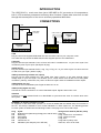
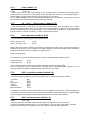
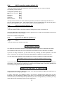
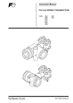
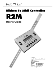
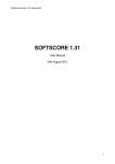
CONNECTIONS
USB
USB
Computer
USB –MIDI
converter
Filter, Gate, CV
Analogue
synth
MIDI IN
MIDI OUT
AUX,
Gate, CV
USB
MIDI Master
keyboard
USB SOLO
USB
Plug one end of the supplied USB cable into here and other end into your computer or hub.
This cable not only carries the MIDI data, but also supplies power to the USB SOLO.
CV (Hz/V)
Plug this into the input marked CV IN, VCO IN, KEY VOLT or KYBD IN etc. on your mono-synth. This
controls the pitch of your synth. (What pitch to play)
GATE (S-Trig)
Plug this into the input marked GATE, V-trig, Trig, S-Trig, etc. on your mono-synth. This turns the note
on and off on your synth. (When to play)
AUX1 [continuously variable aux output]
Plug this into the input marked VCF, fcM, PWM, VCA, Filter, Volume, or any other external control
voltage input on your mon-synth. This enables you to control effects such as filter cut-off using MIDI
controllers. (Velocity, mod wheel, etc.) Note: not all mono-synths have such additional control inputs.
AUX2 [digital aux out]
Use this to control switchable inputs. Signal is either zero or 5V.
AUX3 (clock) [digital aux out]
Use this as a clock connection or to control switchable inputs. Signal is either zero or 5V.
SYNC 24
Connect to an input marked SYNC 24 or DIN SYNC to synchronise the clock of a device which uses
this system.
PRESETS [in memory locations 1 to 40]
As supplied, or after a full reset, presets 1 to 34 are all loaded with the default setup for use with an
SH-101. This setup is suitable for a lot of other standard CV / Gate synths too. The following presets
for other synths are loaded into the following locations. See page 4 for how to load setups.
Prog
#40
#39
#38
#37
#36
#35
Synth
Roland SH-09 (also Moog Prodigy mk1 with KE skts)
Minimoog
Other Moog
Korg MS-20
Yamaha CS-10
ARP2600 (also Odyssey mk1+KE skts)
3
Changes from default (SH-101) setup
Gate 15V
S-trig, coarse tune –5 semitones
S-trig, coarse tune zero
S-trig, Hz/V
S-trig with 5V pullup, Hz/V
Gate 15V, Aux1 set to TRIG
EDITING THE USB SOLO
Switching On
When the USB SOLO is switched on, the words KENTON USB SOLO scroll across the display, and
the unit reverts to the settings from when it was last used.
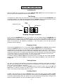
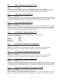
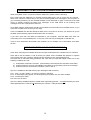
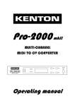
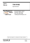
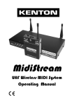
The Display
The display has 3 digits each with a dot above. The 1st dot when lit indicates that PARAMETER mode
is currently selected. The middle dot when lit indicates that VALUE mode is currently selected. The 3rd
dot will light whenever the USB SOLO’s GATE is on (key pressed or sustained).
Parameter mode
Value
mode
Gate On
Minus
Stepping Through Parameters
Ensure that the PARAMETER dot is lit. If you need to, you can change between PARAMETER and
VALUE modes by briefly pressing the SELECT button, you can then use the INC and DEC buttons to
scroll through the available parameters. The available parameters are printed on the case of the USB
SOLO for convenience. For additional confirmation, a “P” will appear in the left digit whenever
parameter mode is selected.
Changing Values
Ensure that the VALUE dot is lit. You can change between PARAMETER and VALUE modes by briefly
pressing the SELECT button. You can then use the INC and DEC buttons to scroll through the
available values. The left digit is used for displaying the hundreds portion of the value if applicable. It
will also have a horizontal dash if a minus value is to be displayed. Minus values up to –127, or positive
values up to 255 are used. The display will automatically revert to parameter mode after approximately
10 seconds if neither inc or dec are pressed. The value you have edited will then be saved to ‘edit’
memory which will be remembered next time you use the USB SOLO.
To speed up editing, the INC and DEC keys will repeat if held. To go faster still, when holding the INC
key then also press and hold the DEC key. Similarly, when holding the DEC key, also press and hold
the INC key.
Storing Setups
Any value you change is automatically stored when reverting to parameter mode (either manually or
after the 10 second timeout). You can also store the current setup to a memory location in the range 1
to 40. These can be recalled at a later date.
To store: select parameter 51, press the SELECT button to show the value, and use the INC and
DEC buttons to select the location you want to store to. Now press & hold the SELECT button (for
approx. 6 seconds) until the display reads ‘sto’ (store).
Loading Setups
To load: select parameter 50, press the SELECT button to show the value, and use the INC and DEC
buttons to select the location you want to load from. Now press & hold the SELECT button (for approx.
6 seconds) until the display reads ‘lod’ (load). You can also load setups using program changes if this
feature is enabled (default is off). See “Boot Menu Options” on page 12.
4
PARAMETERS
Below is a list of parameters available to edit. The letters in square brackets show [where applicable]
what will be shown in thevalue display.
Menu
number
P 01
Parameter (default)
MIDI receive channel (default :1)
Range
1 to 16
- Sets the MIDI receive channel.
P 02
Retrig Time (default: 5)
Range
off [off] and 0.2mS to 5 (mS) approximately – so 5 in display = 1 millisecond
- If set to off (normal trigger mode), the gate just stays on when a new note is played. (no re-trigger)
If set to a number, a valid new note will briefly turn off the gate to retrigger the envelope generators of
your mono-synth. (multiple trigger). The numbers relate to the off time in 200 microsecond increments
approximately.
P 03
Note priority (default: new)
The following can be selected:
Low note priority
High note priority
New note priority
[lo]
[hi]
[nn]
- Sets the note priority for the converter.
If set to "lo" then the lowest valid note played takes precedence.
If set to "hi" then the highest valid note played takes precedence.
If set to "nn" then the newest valid note played takes precedence.
The USB SOLO has a 5 note buffer memory so that trill effects can be achieved.
P 04
Pitchbend range (default: 2)
Range
0 to 12 semitones.
- The pitch bend range can be changed in semitone steps from zero to 12 semitones
P 05
Portamento controller number (default: 65)
- Sets which MIDI controller will turn on/off the portamento function.
The following can be selected:
On
Off
Auto portamento
MIDI controllers
[on]
[of]
[AU]
#0 to 119
always on
always off
normally off but legato playing turns portamento on
values 64 and above =on, 63 and below =off
The standard MIDI controller for portamento on/off is #65 which is the default, but with this command ,
the USB SOLO allows you to use another controller, direct control or Auto Portamento if you wish.
P 06
Portamento time / rate (default :98)
Range
1 to 127
- Sets the portamento (glide or slide) time. This can also be adjusted in real time over MIDI using
controller #5 (portamento time). This number is just a value, it is not calibrated in mS or any other unit.
To turn portamento off, set portamento controller (parameter 05) to off, don’t use this parameter.
5
P 07
Portamento type (default : fixed rate)
The following can be selected:
Fixed rate
[Fr]
Fixed time
[Ft]
- Fixed rate causes the portamento to slide at the rate set in 06, so that the slide time is proportional to
the interval between the start and finish notes.
- Fixed time will attempt to keep the time taken for the slide to be constant, regardless of the interval
between the start and finish notes. (In extreme cases this is not always possible)
P 08
LFO to CV controller number (default: 1)
The following can be selected:
Off
[oFF]
Pitch bend
[Pbd]
Velocity
[VEL]
Aftertouch
[AFt]
MIDI controllers 0 to 119
P 09
LFO to CV minimum value (default: 0)
Range
0 to 127
- Sets the level for LFO to CV modulation when the MIDI controller source is at its minimum.
Note that minimum can be set above maximum so that the controller works backwards.
Why would I want to do this? – You may want a pre-set amount of modulation applied at all times
P 10
LFO to CV maximum value (default: 50)
Range
0 to 127
- Sets the level for LFO to CV modulation when the MIDI controller source is at its maximum.
Note that minimum can be set above maximum so that the controller works backwards.
Why would I want to do this? – The modulation amount at mod-wheel maximum may be too great or
too little
P 11
LFO to CV reset value (default: 0)
Range
0 to +127
- Sets the level the LFO to CV modulation will reset to when the USB SOLO is powered on or when it
receives a controller reset MIDI command or a new setup is loaded from memory. This is equivalent to
a MIDI message of this value being received, so it will be influenced by min and max settings above.
Why would I want to do this? – You may want a pre-set amount of modulation that can however be
turned off later using the mod wheel
P 12
Coarse Tune / Transpose (default: 0)
Range
-24 to +24
- Changing this will change the tuning of the mono-synth in semi-tone steps. If your synth does not
play C when you play a MIDI C (note#36), use this to make it as near as possible.
Why would I want to do this? – Your synth might not play a C when zero volts CV is applied to it, either
because it is out of adjustment, or maybe it was designed that way (e.g. Minimoog – zero volts = F)
P 13
Fine tune (default: 0)
Range
-127 to +127 (approximately a semitone each way – use P12 above if you need more)
- Fine tunes the mono-synth. This moves all notes up and down by the same amount.
6
P 14
Scale (default: 0)
Range
-127 to +127
- This is used to tune in the octave scaling of your analogue synth. It will only need adjusting if your
synth sounds out of tune as you play further up the keyboard (see ‘Tuning in Your Analogue Synth’). Check whether CV type select has been set correctly (see ‘P 15’ below).
Note C (MIDI note#36) will not move (assuming transpose is not in operation) so get that in tune first
then tune the C two octaves above that by using this parameter.
P 15
CV – Hz/V – 1.2V/oct select (default: CV)
- This shoud be set to V/oct [CV] for connecting to most synths, such as Roland, SCI, Octave,
Oberheim or Moog synths. Set it to Hz/V [Hz] if you are using either Yamaha or Korg mono-synths
(except the Monopoly which is volt per octave). A very small number of synths use 1.2 volts per octave
[12] (one tenth of a volt per semitone) – in which case select this option.
P 16
Gate type select (default: G 05)
- you can select the following types for the GATE output:
Gate V-Trig low (+5v)
Gate V-Trig high (+15v)
[g 05]
[g 15]
Gate is the most common signal used for telling a synth when to play its note. The high level Gate is
suitable for most synths, such as Roland, SCI, ARP, Oberheim. The low level gate may be needed for
synths that require a lower gate voltage such as the SH-101.
S-trig no pull-up [S 00]
This would be used for most Moogs & Korgs, and some Yamaha synths instead of Gate.
S-trig low pull-up
S-trig high pull-up
[S 05]
[S 15]
These would be used on some of the Yamaha CS range of synths instead of Gate.
NB – The USB SOLO has an internal DC-DC converter and so can generate gate voltages up to +15
volts even though the power supplied over the USB cable is only 5 volts!
P 20
AUX 1 controller number (default: 16)
- Sets which MIDI controller will control the auxiliary output. The following can be selected:
Trig Pulse
Off
Pitch bend
Velocity
Aftertouch
MIDI controllers
[trg]
[oFF]
[Pbd]
[VEL]
[AFt]
0-119
If ‘Trig Pulse’ is selected, the aux output will send a short trigger pulse whenever a valid new MIDI note
is received – this can be used to drive the envelope generator on synths that require a separate trigger
for this. (Only usually needed by the Arp 2600, Arp Odyssey mk1 and a few modulars)
P 21
AUX 1 minimum value (default: 0)
Range
-27 to +100
- Sets the level for the Auxiliary output when the MIDI controller source is at its minimum.
A value of 10 is approximately 1.05 volt – so 100 is approx. 10.5 volts and –27 is approx. 2.86 volts
Note that minimum can be set above maximum so that the controller works backwards.
7
P 22
AUX 1 maximum value (default: 100)
Range
-27 to +100
- Sets the level for the Auxiliary output when the MIDI controller source is at its maximum.
A value of 10 is approximately 1.05 volt – so 100 is approx. 10.5 volts and –27 is approx. 2.86 volts.
Note that minimum can be set above maximum so that the controller works backwards.
P 23
AUX 1 reset value (default: 0)
Range
0 to 127
- Sets the level the Auxiliary output will reset to when the USB SOLO is powered on or when it receives
a controller reset MIDI command or a new setup is loaded from memory. This is equivalent to a MIDI
message of this value being received, so it will be influenced by min and max settings above.
P 24
Key scale to AUX 1(default: 0)
Range
0 to 127
- Sets the amount of key scaling which is applied to the Aux output (for opening the filter up as you play
notes further up the keyboard. Most synths do this internally even when connected to a CV converter –
however not all do, a particular exception being the Sequential Pro-One. This feature enables keyscale to filter, even when not otherwise available on the synth.
P 25
LFO to AUX 1 controller (default: 17)
- Sets which Controller will control the LFO depth applied to the AUX1 output.
The following can be selected:
Off
[oFF]
Pitch bend
[Pbd]
Velocity
[VEL]
Aftertouch
[AFt]
MIDI controllers
0 to 119
P 26
LFO to AUX 1 minimum value (default: 0)
Range
0 to 127
- Sets the level for LFO to AUX modulation when the MIDI controller source is at its minimum.
Note that minimum can be set above maximum so that the controller works backwards.
P 27
LFO to AUX 1 maximum value (default: 64)
Range
0 to 127
- Sets the level for LFO to AUX modulation when the MIDI controller source is at its maximum.
Note that minimum can be set above maximum so that the controller works backwards.
P 28
LFO to AUX 1 reset value (default: 0)
Range
0 to 127
- Sets the level the LFO to AUX1 modulation will reset to when the USB SOLO is powered on or when
it receives a controller reset MIDI command or a new setup is loaded from memory. This is equivalent
to a MIDI message of this value being received, so it will be influenced by min and max settings above.
P 30
LFO rate / speed (default :116) [approx 6.25Hz]
Range
0 to 191
- Sets the speed of the LFO. Range approx 0.1Hz to 100Hz.
Note: This number is just a numeric value for reference purposes only. It is not calibrated in mS or any
other unit. The scale is roughly logarithmic. Approximately 0=0.1Hz 66=1Hz 129=10Hz 191=100Hz
8
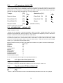
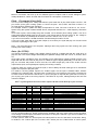
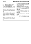
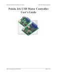
P 31
LFO waveshape (default :TR)
- Sets the LFO waveshape. All waveshapes modulate CV and/or Aux any value between 0 to a positive
value, except triangle, which modulates positive and negative. The following may be selected: (the
downward arrow (↓) indicates the default trigger point when in MIDI sync mode). Note that the sync
point can be changed using parameter #33 – LFO Sync Start Point.
↓
↓
Triangle
[TR]
Sawtooth up [SU]
↓
Sawtooth down
[SD]
PulseWidth 20%
[20]
PulseWidth 40%
[40]
Sample & Hold
[SH]
↓
PulseWidth 10%
[10]
PulseWidth 30%
[30]
Square
[50]
↓
↓
↓
↓
↓
(Pseudo random)
(actually a new S/H level for each trigger)
P 32 LFO MIDI SYNC
(default: oFF)
Range, off [oFF], 1 to 96
- Allows the LFO waveform to be synchronised to MIDI clock, with a variable divide ratio. The LFO
waveform will automatically adjust its length so that it will start at the beginning of a bar, and last for
whatever musical time it is set for (see below for divide ratios).
A divide ratio can be set, so the LFO only re-triggers every so many MIDI clock messages. MIDI sends
24 clocks per quarter note. So if divide is set to 1, there will be 1 cycle of the LFO for every 1 MIDI
clock. (i.e. 24 cycles per quarter note). If set to 24, there will be 1 cycle of the LFO for every 24 MIDI
clocks. (i.e. 1 cycle of the LFO per quarter note).
Below is a table of values you can set the divide ratio to obtain LFO cycles of various musical lengths:
Note type:
Divide ratio:
Semibreve
96
Minim
48
Crotchets
24
Crotchet triplets
16
Quavers
12
Quaver triplets
8
Semiquavers
6
Semiquaver triplets
4
Demisemiquavers
3
Demisemiquaver triplets
2
Do not use low divide ratios at high clock speeds (particularly 1).
P 33
LFO Sync Start Point (default :0)
Range
0 to 255
- Sets where the waveform will start when MIDI sync is active or Key-On reset is on.
P 34
Key-On resets LFO Wave (default :off)
The following can be selected:
Off
[oFF]
On
[ on]
- When on, the LFO waveform is reset to the selected start point whenever a new note is played.
9
P 40
Continue = start - (default: on)
[note - default was off before firmware 1007]
The following can be selected:
Off
[oFF]
On
[ on]
- when set to on, all continue messages are treated as if they were MIDI start messages.
- when set to off, continue messages will only be treated as start if immediately preceded by a song
position pointer = zero message. Some sequencers use this instead of a start message.
Affects both the sync 24 output and aux output when in clock mode.
P 41
Clock divide ratio - (default: 2)
available values c24, c48 & d2 to d24,
- sets the ratio of MIDI clocks to output pulses from the aux3 output set to clock mode
c24 – special drum machine mode – outputs 24 cpqn – used for many drum machines
c48 – special drum machine mode – outputs 48 cpqn – for Linn & Oberheim drum machines
N.B. Some drum machines use other values e.g. the Roland CR78 uses 12 cpqn (div ratio 2)
If set to 2, there will 12 pulses from the aux output for every 24 MIDI clocks = 12 cpqn
If set to 24, there will be 1 pulse from the clock pulse output for every 24 MIDI clocks = 1 cpqn
(Note there are 24 MIDI clocks per quarter note)
Below is a table of values you can set the divide ratio to in order to obtain a clock pulse at various
musical time intervals:Note type
Divide ratio
CPQN (clocks per quarter note)
Crotchets
(quarter notes)
Crotchet triplets
Quavers
(eighth notes)
Quaver triplets
Semiquavers
(sixteenths)
Semiquaver triplets
Demisemiquavers
Demisemiquaver triplets
24
16
12
8
6
4
3
2
1
P 42
2
4
6
8
12
AUX 2 controller number (default: 18)
- Sets which MIDI controller will control AUX2 output
The following controllers can be selected:
Clock Stop/Start
Off
Pitch bend
Velocity
Aftertouch
MIDI controllers
[S t t]
[oFF]
[Pbd]
[VEL]
[AF t]
0-119
Note that this is a switch output and will be 0 volts or 5 volts depending on the MIDI data value and the
threshold setting below.
P 43
AUX 2 threshold (default: 64)
Range
1 to 127
- Sets the threshold at which the AUX2 output will change from 0 to 5V or from 5V to 0.
If the MIDI data value of the selected controller is greater than or equal to the threshold then AUX2 will
be on (5V), otherwise it will be off (0V).
Note: Does not affect Clock Stop/Start
10
P 44
AUX 3 controller number (default: 19)
- Sets which MIDI controller will control pin 3 of the thru socket if Aux 2+3 mode is selected
The following can be selected:
Timing Clock (inverted)
Timing Clock (normal)
Off
Pitch bend
Velocity
Aftertouch
MIDI controllers
[CL i]
[CLK]
[oFF]
[Pbd]
[VEL]
[AF t]
0-119
If timing clock is selected, the clock divide ratio (para #41) controls the relationship with MIDI clock.
CLK is a normal positive clock – most synths use this. CLi is an inverted clock, 5V at rest and gives a
pulse to zero to signal a clock – used on some synths such as Korg Monopoly.
P 45
AUX 3 threshold (default: 64)
Range
1 to 127
- Sets the threshold at which the AUX3 output will change from 0 to 5V or from 5V to 0.
If the MIDI data value of the selected controller is greater than or equal to the threshold then AUX3 will
be on (5V), otherwise it will be off (0V).
Note: Does not affect Timing Clock
P 46
Sysex Device Number (default :1)
Range
1 to 16
- Sets the sysex device number for this unit.
OTHER USEFUL INFO
The USB SOLO will always respond to controller #64 (sustain pedal) with no adjustment necessary.
One intended use for Auxes 2+3 is to control the accent & slide of our 5 socket kit for the TB-303.
If you are not using a sequencer, you will need some way of linking your MIDI keyboard to the USB
SOLO. For the PC, we recommend a program called MidiOX, available from www.midiox.com
You can use program changes to load programs from memory if enabled in “Global Parameters”
RESETTING THE USB SOLO TO FACTORY DEFAULTS
If you wish to reset your USB SOLO, you can do so by turning the unit on whilst holding down all three
push buttons. This will return the USB SOLO’s settings to their default values. ‘Fd’ (factory defaults) will
momentarily be displayed when this has been done.
TUNING THE USB SOLO TO YOUR SYNTH
It may be that your synth is slightly out of tune, so it will be necessary to adjust the USB SOLO to
compensate for the tuning of your synth.
1, Firstly, ensure that your analogue synth is as in-tune as possible when playing from its own
keyboard. Do this by adjusting the tuning or pitch knob on your analogue synth whilst playing middle C
on both this and your master keyboard (or whatever you use for tuning reference). To do this, you may
need to disconnect the analogue synth from the USB SOLO.
11
2, Connect the converter to your analogue synth and MIDI system. Check the USB SOLO is switched
to the correct scaling system, Hz/V for Korg and Yamaha, or V/oct for anything else (see Editing
Parameters section). Set transpose to zero. Now press bottom C (MIDI note #36) on your digital synth.
Both synths should sound, don’t worry at this stage if they are not in tune.
3, Using bottom C (MIDI note #36) as a reference (you must use this note for maximum accuracy) tune
in the USB SOLO with your analogue synth by adjusting the parameter FINE TUNE and TRANSPOSE
if necessary (see Editing Parameters section) until it is exactly in tune.
4, When your digital & analogue synths are in tune at the bottom , play middle C, two octaves up on
your digital synth. (MIDI note #60). Now adjust the SCALE parameter (see Editing Parameters
section) until both synths are in tune. The analogue synth should now play correctly across it’s
complete range from your master keyboard, if this is still not the case go back to step 3 and repeat the
process for final tweaking.
CHECK LIST FOR SETTING UP THE USB SOLO
12345-
Make sure all cable connections have been made.
Set MIDI receive channel you wish to use.
Make sure you have set the GATE output correctly to either ‘Gate’
or ‘S-Trig’ type triggers.
Make sure you have set the CV output correctly to either ‘V/oct’
or ‘Hz/V’.
You may wish to adjust the AUX, or any other settings to those that
work best for your set-up.
√
√
√
√
√
BOOT MENU OPTIONS
Some combinations of buttons can be pressed at power up to adjust settings or enter other operational
modes. First ensure the power switch is off, press the required button or buttons, then turn the power
switch on. The various modes are described below.
SEL only
DEC only
INC only
SEL & DEC
SEL & INC
SEL & DEC & INC
– Enters MIDI analyser mode [displays ANL] described on page 13
– Enters Global Parameters mode [displays GPA] decribed below
– Displays the firmware revision number, described below
– Powers-up without USB (from plugging cable in only) [displays NoU]
– Receive firmware upgrade [displays rFU] described below
– Reset to factory defaults [displays Fd] – described on page 11
Global Parameters Mode:
Releasing the DEC button shows ‘Prg’ the only option available here at present.
Press INC to enable program changes to load in memories 1 to 40
Press DEC to disable program changes to load memories (default).
Firmware revision:
While the INC button is held, the firmware revision number [1xxx] will be displayed in pairs – two
dashes then digits 1 & 2 then digits 3 & 4 repeated. Releasing the INC button will revert to the normal
operational mode.
Receive firmware upgrade:
Releasing the buttons may briefly display 1 [start] and will then show 2 [ready]. The 2 indicates that the
USB SOLO is ready to receive the upgrade. Now send the firmware upgrade (see instructions included
in the firmware upgrade zip file) – the 2 should flash while the dump is being received then number 3
[all received] followed quickly by 4 [CRC check OK], then after about 5 seconds a steady 5. The 5
indicates the update has been successful. Wait 10 seconds then unplug & replug the USB cable to
resume operation with the new firmware. (NEVER UNPLUG WHILE THE 4 IS SHOWING)
Possible error states: hangs at stage 2 = not enough bytes received. 8 shows – dump is corrupt
For both of the above situations, unplug the USB cable and start again. (Don’t use the on/off switch)
It is essential that power is maintained to the USB SOLO during the firmware upgrade process.
Failure of power during stage 4 will leave the unit unusable and require return of the unit to
Kenton. We consequently recommend that the upgrade process is only carried out while your
host device (computer) is powered from the mains.
12
MIDI ANALYSER MODE
The USB SOLO has a built-in MIDI analyser function. This feature allows you to see what types of MIDI
messages are being transmitted by your master keyboard/sequencer making the USB SOLO a useful
diagnostic tool.
To enter analyser mode, you must power on the USB SOLO whilst holding the SELECT button. The
display will then show ‘AnL’ for analyser. Releasing the select button shows ‘rC’ for receive channel &
status mode. This means the display will show the MIDI receive channel of any messages it receives in
the right hand two digits, and will show status in the left digit – this is explained further down the page.
Using the INC, DEC, and SELECT buttons, different types of received MIDI messages may be
displayed:
SELECT
Short press
Long press
Short press
Long press
Short press
Long press
DEC
INC
[rC] Receive channel & status
[PC] Program change
[nt] Note number
[nv] Velocity
[Cn] Controller number
[Cv] Controller value
For whichever of the above selected, the USB SOLO will display the value it receives for the type of
message currently selected.
Although pitchbend and after-touch are not strictly controllers, when Controller number [Cn] mode is
selected, ‘pb’ will be displayed if a pitchbend message is received, and ‘af’ will be displayed if an aftertouch message is received.
If Controller value [Cv] mode is selected, and pitchbend or after-touch messages are received, their
values will be displayed.
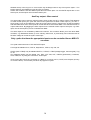
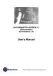
When Receive channel & status [rC] mode is selected, the right hand 2 digits show the received MIDI
channel (if applicable) and the left hand digit operates as a received MIDI message indicator. LED
segments will flash when then following types of messages are received: Note on, Note off, Sysex,
Timing clock (MIDI clock), Start, Stop, Continue.
Any MIDI
message
Clock start
Clock
continue
Sysex
MIDI clock
Note on
Note off
Clock stop
The top left dot (any MIDI message) operates in all modes, not just for Receive Channel & Status
mode.
To exit MIDI analyser mode, the power switch of the USB SOLO must be turned off then on again.
13
PROBLEMS YOU MAY ENCOUNTER WHEN USING MIDI CLOCK
When using MIDI clock in conjunction with the USB SOLO, please note the following.
First, ensure that the USB SOLO is actually receiving MIDI clock. This is not as silly as it sounds there are a number of reasons why it may not be receiving MIDI clock messages in the first place. If
you are having problems, go into the MIDI analyser mode described on page 13 and see if the USB
SOLO is actually receiving the MIDI clock messages. If the USB SOLO is not receiving clock
messages, here are a few points to watch for:Some MIDI mergers & patch bays actually remove MIDI clock information from the data stream, or you
may have to enable it for the port you are using.
Users of CUBASE note that the default for MIDI clock is for it NOT to be sent, you will have to go into
the MIDI synchronisation page and select MIDI clock to transmit.
If you have more than one MIDI port attached to your computer, note that MIDI clock does not
necessarily come out of all MIDI ports – it may only come out of a pre-assigned or selected one.
There is more information about MIDI clock problems on our website in the “Information and FAQs”
section.
MORE ABOUT MIDI CLOCK ON THE USB SOLO
Clock Stop / Start signal is available at the Aux 2 output if selected as the controller source. Para #42.
Clock with a rate of between 1 and 48 clocks per quarter note is available with positive or negative
going pulses at the Aux 3 output if selected as the controller source. See parameter #44.
The clock rate is selectable using parameter #40. Note that no output will happen unless one of the
following conditions are met:
1) A MIDI start command is received. (Unfortunately not all sequencers send start commands)
2) A MIDI continue is received, immediately preceded by a song position pointer zero message.
3) A MIDI continue is received and “continue = start” is set on.
Sync 24 is available at the DIN socket (5 pin 180 degree DIN connector)
Pin 1 - Stop = 0 volts / 1Start = +5 volts (or continue if selected)
Pin 3 - 5 volt positive going pulses; 24 clocks (pulses) per quarter note, the same as MIDI
Pin 2 - Ground (zero volts)
Pins 4 & 5 are not used.
Sync 24 is always available subject to a MIDI clock signal being present – it is not affected by the clock
divide parameter #41, however it is affected by the continue = start parameter #40.
14
A BRIEF GUIDE TO MIDI TO CV CONVERSION FOR THE BEGINNER
MIDI-CV converters can have up to four different types of outputs used to control analogue synths,
usually labelled CV, GATE, S-TRIG and AUX. Below is a description of what they do:
Pitch - CV outputs (V/oct, Hz/V)
The CV (control voltage) is a voltage that tells the synth what note to play. Most synths use the 1 Volt
per Octave (V/oct) pitch scaling system to control the pitch. This means, that each octave is 1V
(V=volts) apart (or 0.0833V per semitone).
For example, bottom C (MIDI note #36) corresponds to 0 Volts. The next C will be 1V, 2V, 3V etc..
Synths using this system include Roland SH101, Sequential Circuits Pro 1, ARP Odyssey, Oberheim
OB 1.
Some other synths, most notably Korg and Yamaha, use a different pitch scaling system. This is an
exponential method called Hertz per volt (Hz/V). This means that for the next octave up, the voltage is
doubled. So bottom C (note#36) will be 0.25V, the next C will be 0.5V, 1V,2V, 4V etc.
If you are not sure which C is MIDI note #36, use MIDI analyser mode to check.
If you use a Hz/V synth with a V/oct pitch output (or vice-versa), the synth will play out of tune but will
not cause any damage to the synth.
Note - The Korg Monopoly is an exception. Although other Korg synths use Hz/V scaling, this synth
actually uses V/oct scaling.
Gate - (Or S-TRIG)
The GATE (sometimes called V-trig [voltage trigger]) signal is a voltage that tells the synth when to
play the note. The GATE voltage will usually be a positive voltage when the note is on, and 0V when
off.
Some other synths, like Moog, Korg, and Yamaha, use S-TRIG (Short Trigger) instead of GATE. This
signal still tells the note when to play, but it is a different type of signal (electrically). To tell the note to
play, the converter will provide a short circuit at it’s S-TRIG output (0V), and to turn off the note the
output will be open circuit (literally like opening and closing a switch).
A point to watch for: unless you know the synth, it will not always be clear what type of CV and GATE
signals are required to play the synth.
For instance, the Korg MS20 requires an S-TRIG signal, but the input is labelled TRIG. Another
example is the Yamaha CS5. The pitch input is marked CV, but requires a Hz/V signal. The best way
to check is either ask someone who knows, or just try all types of output till the synth works correctly. If
you do plug your synth to the wrong outputs, it shouldn’t do any harm, although always start out with
minimum voltages.
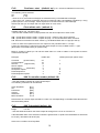
Here’s a general guide to the most common synths and how to hook them up to your converter
SYNTH MODEL
MINIMOOG
CV OR
HZ/V?
CV
S-TRIG OR
GATE
S-TRIG (5V)
MOOG PRODIGY
MOOG ROGUE
MOOG SOURCE
ROLAND SH-101
ROLAND MC-202
ROLAND TB-303
SEQUENTIAL PRO-1
KORG MS-10/20
KORG 700S/770
KORG MONOPOLY
YAMAHA CS-10/20/30
ARP ODYSSEY (&AXXE)
ARP 2600
OCTAVE CAT/KITTEN
CV
CV
CV
CV
CV
CV
CV
HZ/V
HZ/V
CV
HZ/V
CV
CV
CV
S-TRIG (5V)
GATE (5V)
S-TRIG (5V)
GATE (5V)
GATE (5V)
GATE (5V)
GATE (15V)
S-TRIG (5V)
S-TRIG (5V)
GATE (15V)
S-TRIG (5V)
GATE (15V)
GATE (15V)
GATE (15V)
AUXILIARY
CONNECTIONS
FILTER OR
LOUDNESS
FILTER
CLOCK IN (SYNC)
FILTER (SEE RIGHT)
FILTER
ANY OTHER
FILTER
VCF/PORTAMENTO
NOTES
CINCH-JONES CONNECTOR NEEDED
KIT AVAILABLE FOR FILTER IF NOT FITTED
KIT AVAILABLE FOR FILTER
KIT AVAILABLE FOR FITLER
KIT AVAILABLE FOR FILTER/MODULATION
KIT AVAILABLE FOR CV/GATE/FILTER/SLIDE
KIT AVAILABLE FOR CV/GATE/FILTER/SLIDE/ACCENT
THERE ARE MANY EXTRA INPUTS ON THE MS10/20
KIT AVAILABLE FOR CV/GATE AND FILTER
ARPEGGIO CAN ALSO BE CONTROLLED
FILTER AVAILABLE FOR CS-5
KIT AVAILABLE FOR FILTER
FILTER
FILTER
This is a general guide only, further socket kits are available, and many other synths can be controlled.
There simply is not the space to detail all connections to all synths. However if you visit our website you
will find more information there.
A further point to watch for. Some synths use stereo jacks for the CV and GATE connections. Moog,
for instance, use a stereo jack for CV In/Out, and a stereo jack for S-TRIG In/Out on some synths.
15
Whether the tip or the ring is in or out is hard to say as Moogs seem to vary from synth to synth! – The
Rogue however uses RING for inputs and TIP for outputs.
Octave who made the Cat and Kitten synths also use stereo jacks. CV and GATE outputs are on one
stereo jack, and the inputs are on another stereo jack.
Auxiliary output - More control
The AUX output can be used to control functions such as filter cut-off or volume control. This depends
on what control inputs your synth has. Most mono-synths have at least a Filter input, e.g. the Pro 1.
Some synths, such as the Minimoog, also have VCA inputs (volume). Synths such as the Korg MS20
and ARP 2600 have even more inputs to control effects such as Pulse Width. The USB SOLO has an
output called AUX. By plugging the AUX output into the external control input of the synth, e.g. Filter
input, the cut-off frequency can be controlled over MIDI.
The AUX output is not controlled by MIDI note numbers. The converter allows you to set which MIDI
controller, e.g. Modulation Wheel, (or even velocity, after-touch, or pitch bend), will control the level of
the AUX voltage to control the synth’s extra input.
Only synths that have the appropriate inputs can be controlled from a MIDI-CV
converter.
The synth needs some sort of CV and GATE inputs.
CVs might be labelled CV In, OSC In, Keyboard In, VCO In, Key Volt, etc.
GATEs (and S-TRIG) may be labelled GATE In, S-TRIG, V-TRIG (voltage trigger, same as gate), Trig
In, etc.
Any additional inputs may be utilised, like Filter, VCF fcM, VCF, PORTA (portamento), Loudness,
VCO, PWM, etc. by using the converter’s AUX output.
Some synths that cannot be connected to a MIDI-CV converter via CV, GATE, AUX Outputs (as they
do not have them). This includes just about all polyphonic synths.
16
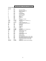
STANDARD MIDI CONTROLLER NUMBERS
Controller Number
Control Function
Decimal
0
1
2
3
4
5
6
7
8
9
10
11
12-15
16-19
20-31
32-63
64
65
66
67
68
69
70-79
80-83
84-90
91
92
93
94
95
96
97
98
99
100
101
102-119
120-127
Bank select MSB
Modulation wheel/lever
Breath controller
Undefined
Foot controller
Portamento time
Data entry MSB
Main volume
Balance
Undefined
Pan
Expression controller
Undefined
General purpose controllers (1-4)
Undefined
LSB for controllers 0-31
Damper pedal (sustain) (Hold 1)
Portamento
Sostenuto
Soft pedal
Undefined
Hold 2
Undefined
General purpose controllers (5-8)
Undefined
External effects depth
Tremolo depth
Chorus depth
Celeste (detune) depth
Phaser depth
Data increment
Data decrement
Non-registered parameter number LSB
Non-registered parameter number MSB
Registered parameter number LSB
Registered parameter number MSB
Undefined
Reserved for channel mode messages
Hex
00H
01H
02H
03H
04H
05H
06H
07H
08H
09H
0AH
0BH
0C-0FH
10-13H
14-1FH
20-3FH
40H
41H
42H
43H
44H
45H
46-4FH
50-53H
54-5AH
5BH
5CH
5DH
5EH
5FH
60H
61H
62H
63H
64H
65H
66-78H
79-7FH
17
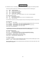
SYSEX CONTROL
The USB SOLO can be controlled by SysEx (System Exclusive) messages in the following formats:
The first five bytes of SysEx for the USB SOLO are always the same for all data types
[
[
[
[
[
[
1]
2]
3]
4]
5]
6]
0F0h
00h
20h
13h
0Fh
zzh
- Sysex command
- Company ident first byte
- Company ident second byte
- Company ident third byte
- Product code – USB SOLO
- where zz is 0 - 0Fh = device number 1-16 or 7Fh = firmware upgrade
For program dump request:
[ 7]
10h - program dump request
[ 8]
xx
- prog number to dump from (1 to 40) or 0 = edit buffer (current)
[ 9]
0F7h - end of exclusive
The USB SOLO responds by sending a program dump in the format given below for dump receive
For info change:
[ 7 ] 20h
- info change
[ 8 ] 0uuuuuuu - where uuuuuuu = high 7 bits of parameter address (always zero for usb solo)
[ 9 ] 0hhhhhhh - where hhhhhhh = low 7 bits of parameter address
[ 10 ] 0uuuuuuu - where uuuuuuu = high 7 bits of data (either 0 or 1 for usb solo)
[ 11 ] 0hhhhhhh - where hhhhhhh = low 7 bits of data
[ 12 ] 0F7h - end of exclusive
The USB SOLO responds by changing the specified data and updating the display if necessary.
Parameter data are accessed at the addresses shown on the following page.
For program dump receive:
[ 7 ] 40h
- program dump receive
[ 8 ] xx
- prog number to dump from (1 to 40) or 0 = edit buffer (current)
[ 9 ] 0uuuuuuu - where uuuuuuu = high 7 bits of data (either 0 or 1 for usb solo)
[ 10 ] 0hhhhhhh - where hhhhhhh = low 7 bits of data
9 & 10 above are repeated 48 times (for 48 bytes of data)
[ 105 ] 0F7h - end of exclusive (total bytes 105)
For firmware upgrade:
[ 7 to 65406] = 65400 bytes - where 57225 bytes of 8 bit code are packed as 65400 bytes of 7 bits
[ 65407 ]
0F7h - end of exclusive (total bytes 65407)
Note that USB SOLO must be set in special firmware receive state to receive this dump. See “boot
menu options” on page 12.
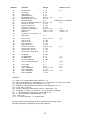
18
Address
Function
Range
Notes (see end)
00
01
01
03
04
05
06
07
08
09
10
11
12
13
14
15
Receive chan
trig / retrig
note priority
pitchbend range
portamento cont #
portamento time / rate
portamento type
LFO to CV depth controller #
LFO to CV min val
LFO to CV max val
LFO to CV reset val
coarse tune / transpose
fine tune val
scale val
v/o or hzv or 1.2v select 0 - 2
gate select
0 - 15
0 - 25
0-2
0 - 24
253 - 0 - 119
0 - 127
0–1
252 - 0 - 119
0 - 127
0 - 127
0 - 127
232 > 0 > 24
129 > 0 > 127
129 > 0 > 127
{1}
16
17
18
19
20
21
22
23
24
Aux1 Cont #
Aux1 min val
Aux1 max val
Aux1 reset val
Key scale to Aux
LFO to Aux1 cont #
LFO to Aux1 min val
LFO to Aux1 max val
LFO to Aux1 reset value
251 > 0 > 119
0 - 127
0 - 127
0 - 127
0 - 127
252 - 0 - 119
0 - 127
0 - 127
0 - 127
25
26
27
28
29
Lfo speed
Lfo waveshape
Lfo MIDI sync
Lfo sync start point
Key-on resets LFO wave
0 - 191
0-8
0 - 96
0 - 255
0-1
30
31
32
33
34
35
cont = start
clock divide
Aux 2 controller #
Aux 2 threshold
Aux 3 controller #
Aux 3 threshold
0-1
0 - 24
252 > 0 > 119
1 – 127
252 > 0 > 119
1 - 127
{3}
0=fixed rate / 1= fixed time
{4}
{2}
129>0 = -ve
129>0 = -ve
0-4
{6}
{4}
{7}
{8}
{ 10 }
{ 11 }
{9}
{6}
{6}
{ NOTES }
{ 1 } Data 0 - 15 corresponds to MIDI channels 1 - 16
{ 2 } 232 = -24 semitones 0 = no transpose 24 = + 24 semitones - 25 to 231 are invalid
{ 3 } 253=pmt off 254=pmt on 255=auto pmt & 0 - 119
{ 4 } 252=ignore 253=pitchbend 254=velocity 255=aftertouch & 0 - 119
{ 5 } 0= -64 64=0 127=+63
{ 6 } 251=trig 252=ignore 253=p.bend 254=vel 255=aft & 0 - 119
{ 7 } 0= triangle 1= saw up 2= saw down 3= 10% pulse etc. as display
{ 8 } 1 - 96 corresponds to sync divide 1 to 96 and 0 = off
{ 9 } 0 - 23 corresponds to arpeggio divide 1 to 24
{ 10 } 0=off 1=on
{ 11 } 0 = continue ignored 1 = continue=start
All sysex addresses and data are range checked and out-of-range values
will either be ignored or adjusted to give a valid response.
19
SPECIFICATIONS
Power Input
Power is supplied by the USB host device via the USB cable
Power consumption
105mA max
MIDI
In & Out (via USB)
Analogue outputs
CV on 3.5mm mono jack (V/oct or Hz/V or 1.2V/oct)
Gate on 3.5mm mono jack (Gate or S-trig – with or without pullups)
Aux1 on 3.5mm mono jack
Digital outputs
Aux2 & Aux3 on 3.5mm mono jacks (off=0 volts on=+5 volts)
Sync 24 on 5 pin 180 degree DIN socket
Weight
450g
Dimensions
130 x 97 x 40 mm
D to A conversion
2 x 16 bit high quality / low drift DACs
Non-volatile memory
EEPROM (no back-up battery required)
Processor
32 bit ARM processor
USB connector
Type B socket – USB A to B cable supplied 1.8 metre
WARRANTY
The USB SOLO comes with a 12 month (from purchase date) back to base warranty, (i.e. customer
must arrange and pay for carriage to and from Kenton Electronics).
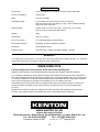
WEEE DIRECTIVE
Correct disposal of this product at the end of its working life.
(applies to the European Union & other European countries with separate collection systems)
The crossed-out wheelie bin symbol affixed to this product indicates that it should not be disposed of
with other household wastes at the end of its working life. To prevent possible harm to the environment
or to human health from uncontrolled waste disposal, please separate this from other types of wastes
and recycle it responsibly to promote the sustainable re-use of material resources.
Household users should contact either the retailer where they purchased the product, or their local
government office for details of where and how they can take this item for environmentally safe
recycling.
Business users should contact their supplier and check the terms and conditions of the purchase
contract. This product should not be mixed with other commercial wastes for disposal.
www.kenton.co.uk
Kenton Electronics Limited
Brookfarm House, Station Road, South Wimbledon, London, SW19 2LP, UK
Tel: +44 (0)20 8544 9200
Fax: +44 (0)20 8544 9300
Firmware version #1007
e. & o. e. 2nd August 2012
20