1
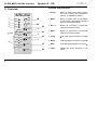
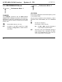
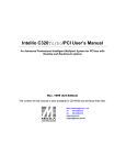
doepfer System A - 100 1. Introduction A To install the A-190 please look at the important information on p. 4! The A-190 is a MIDI-CV/SYNC Interface, with which you can control any A-100 Module which has CV and gate/trigger input sockets by MIDI. The A-190 has two Digital-to-Analogue converters (DAC for short), which put out control voltages from 0 V to +5 V, so that you can control not just the pitch, but also another voltage-controllable parameter on the A-100. DAC 1 is ‘hard-wired’ to receive MIDI note messages and convert them into control voltages available at CV output socket CV 1. The DAC has 12-bit resolution, which gives excellent tuning resolution (in steps of 1/4096th). As a rule, DAC 1 will be used to control VCO pitch. DAC 2 can be assigned to your choice of MIDI controller. This DAC has 7-bit resolution (1/128th steps). Its output is available at CV 2, and can be used for voltage control of any suitable module (eg VCF, VCA, etc.). MIDI-CV/SYNC Interface A-190 The A-190 also has a clock output, controlled by MIDI clock. This can be divided down to provide a variety of clock outputs, and enable older sequencers or drum machines to be synced to MIDI. A Reset Output provides control of the A-160 / 161 Clock Divider / Sequencer or can produce MIDIsynchronised gates (for instance on an ADSR). MIDI START or CONTINUE messages make the voltage at the Reset output go low, and MIDI STOP messages make it go high. In addition, the A-190 allows for portamento (glide) and pitch-bend, and provides a software LFO. These functions can all be switched on and off or altered by MIDI controllers. All control parameters can be saved in non-volatile memory. H The A-190 needs an additional power supply (+5 V / 50 mA) for connection to the system bus. 1 A-190 MIDI-CV/SYNC Interface System A - 100 Controls and indicators 2. Overview A-190 MCVS 1 Group : Button to select which menu section (out of the Config and Performance menus), is available for editing 2 Menu : Button to select items in Edit Mode, choose items to be edited, and select items in Performance Mode 3 INC / + : Button for increasing a parameter value by one step at a time 4 DEC / - : Button for decreasing a parameter value by one step at a time 5 Clock : LED clock signal indicator for output § 6 Reset : LED reset signal indicator for output $ 7 Gate : LED gate signal indicator for output % 8 LEDs : Indicate the menu selected in edit mode MIDI-CV/SYNC INTERF. ➀ ➁ ➂ ➃ MIDI Thru Group Menu MIDI In Inc./+ Dec./Group AH ➇ Perform. Clock × Ø CV 1 LFO Frq. Clock Glide Offset Assign Scale Arpeg. Retrig. Reset Gate CV 1 CV 2 CV 2 2 ➄ Config. Channel Bend W. doepfer ➅ ➆ System A - 100 doepfer MIDI-CV/SYNC Interface A-190 In / Outputs ! MIDI THRU : Output for relaying MIDI messages sent to MIDI IN to another MIDI unit. " MIDI IN : Input for MIDI messages. § Clock : MIDI clock signal (or divided version) output. $ Reset : Reset signal output:MIDI-Start or Continue): low voltage MIDI-Stop: high voltage. % GATE : GATE signal output; normally connected internally to the A-100 system bus (INT.GATE line), but can be disconnected. & CV 1 : Output for control voltage 1 (D/A converter 1); normally connected internally to the A-100 system bus (INT. CV line), but can be disconnected. / CV 2 : Output for control voltage 2 (D/A converter 2). H N.B.: On the front panel of the first production series , the arrows were accidentally printed the wrong way round. In these instructions, though, all the functions, for instance selecting a menu group, are described correctly (see p. 6). Group Perform. × Channel Config. Ø CV 1 3 A-190 MIDI-CV/SYNC Interface System A - 100 3. Starting to use the A-190 A N.B. if you’re using more than one A-190: The A-190 is normally connected up to the INT.CV und INT.GATE on the system bus. If you want to run more than one A-190 with only a single system bus, then only one of the A-190s must be connected to the system bus. doepfer H The gate output % and CV1 output & are automatically connected to the system bus of the A-100, so don’t use patch cables to connect these, unless you have cut the links, or wish to connect to a module whose system bus isn’t connected with the A-190’s (have a look at the note on using more than one A-190). VCOs on the same system bus automatically receive CV1, and ADSRs automatically receive the gate signal. Output Connection notes Disconnect the other A-190 modules from the system bus, by cutting the two links labelled CV1 and GATE (near the bus ribbon connector on the A-190 board). / CV 2 Any module’s CV input (for instance a VCF’s CV input, for controlling the filter cut-off point). Before switching your system on, use a MIDI cable to connect between your MIDI instrument and the A-190: § Clock For instance, the A-160’s trigger input for MIDI-synced sequences. D Connect the A-190’s input socket MIDI IN " to the MIDI OUT socket of your MIDI instrument (master keyboard, MIDI synth, MIDI sequencer, etc.). $ Reset The A-160’s reset input, for MIDI control of start and stop messages; the A-140’s gate or retrigger input for MIDI-synchronised envelopes. D Now switch your System A-100 on. The Gate LED 7 will briefly light up, to show you the A-190’s software version (one blink = Version 1, etc.). D Patch the outputs of your A-190 to corresponding modules on the System A-100: 4 D Use the CONFIG and PERFORM menus to tailor the MIDI set-up to your requirements. System A - 100 doepfer and portamento time - the sort of parameters to which you need easy and frequent access . 4.1 Using the A-190 On power up, the A-190 defaults to Performance mode. This is the normal mode of operation, in which the incoming MIDI information is converted to CV, gate and clock signals, according to the A-190’s settings. You can check you’re in performance mode by seeing if all the menu LEDs (8) are off. The gate LED 7, reset LED 6 and clock LED 5 will light up in response to MIDI activity: Clock Performance-Mode MIDI-CV/SYNC Interface A-190 Reset Gate The Config menus, on the other hand, contain configuration parameters, which are fundamentally important to the whole MIDI set-up, but as a rule don’t need to be changed often (for instance gate polarity, voltage response, or re-trigger time). To alter parameters, you need to be in edit mode. The procedure is as follows: • Select the menu group • Switch to edit mode • Select the menu which contains what you want to edit • Alter the parameters either manually or by MIDI Since the A-190 gives you so many options for changing the way MIDI information is converted, it was necessary to use a menu system for setting the various parameters. There are two groups of menus, with six menus in each. The performance menus are where you can change important playing parameters such as bend width • Return to performance mode. Selecting menu group The A-190 is designed so that, after power up, the first time you enter edit mode, you automatically go to the performance menu group. 5 A-190 MIDI-CV/SYNC Interface System A - 100 Pressing the Group button 1 switches to the other menu group - the button acts as a toggle switch. A mini-light-show indicates which group is selected: doepfer Edit Mode, Menu 1 Sequence of lights Sequence of lights Performance Menu Config Menu For example, if, after switching on, you need to alter GATE POLARITY in Config Menu 1, press the Group button 1 once. The light sequence goes upwards from the bottom LED, and tells you that when you press the edit button you will be in the Config Menu. You can tell which menu group you’re in by checking the speed at which the LED (8) blinks: slow blink : Config menu fast blink : Performance menu H (Symbols in the text: 0 : slow 2 : fast) Menu selection Changing to edit mode When in performance mode, switch over to edit mode by pressing the MENU button 2. The top LED flashes, to tell you that you’re in edit mode, and can now access the parameters in the first menu in the group you selected with the group button: 6 If the parameter you want to edit isn’t in the first menu, scroll through the other menus by repeatedly pressing the MENU button 2 (see the diagram on the next page). System A - 100 doepfer ... MENU MENU Edit-Mode MIDI-CV/SYNC Interface A-190 Switching back to performance mode MENU PerformanceMode Changing parameters There are two ways of changing parameters on the A-190: either manually, or by sending the appropriate MIDI messages, which the A-190 ‘learns’. Whenever possible, use the latter method, ‘MIDI learning’. In chapters 4.2 and 4.3, the symbols M (MIDI learning) and m (manual) show the different methods possible. In manual mode, use the INC button 3 to increase a parameter by one, and the DEC button 4 to decrease it by one. All the LEDs flash once together each time a change is made. When you’ve made the change to the parameter you wanted to alter, you can either change other parameters in the same menu, or go on to the next menu by pressing MENU button 2. Repeatedly pressing the MENU button takes you through all the menus, and then back to performance mode - signified by all the menu LEDs (8) being off (see the diagram at top left). H If you’ve edited a parameter in one menu group, and want to edit one in the other, it’s necessary to go back to performance mode first. Then you can press the Group button 1 to switch to the other menu group. H You can find a table showing all the parameters in the CONFIG and PERFORMANCE menus, as well as all the MIDI controllers, on page 23. In MIDI learning mode, parameters are changed by sending appropriate MIDI messages to the A-190. For example, in Config menu 1, the MIDI message “PROG CHANGE 3" switches CV CHAR. (the type of pitch control voltage sent out) to V/Octave. 7 A-190 MIDI-CV/SYNC Interface System A - 100 4.2 CONFIG menus 0 CV 1 H Config Menu 1 The CHANNEL parameter sets the MIDI receive channel. In performance mode, MIDI messages received on this channel are converted to CV and gate signals and sent to whichever modules are connected to the A-190 - either via the system bus or via patch leads. [m m ch : n: 8 ch n MIDI channel MIDI note number vel Change the bottom MIDI note (0 to 127) ] GATE POLARITY This parameter sets the polarity of the gate voltage. H For use with the A-100, this parameter should always be set to positive. The only time you may need to alter it is to control certain other makes of synthesizer. M positive: REF. NOTE sets the bottom note on the MIDI keyboard which will play the lowest note on the A-100 VCOs. As a rule, this is MIDI note number 36. NOTE ON Note that playing a note on the keyboard will set MIDI channel and bottom note at the same time. This method of setting the MIDI channel is preferable to the performance mode method, which has no confirmation. CHANNEL / REF. NOTE M doepfer negative: +12 V .... 0 V .. +12 V. 0 V ... PROG CHANGE 1 PROG CHANGE 2 System A - 100 doepfer MIDI-CV/SYNC Interface A-190 CV CHAR. RETRIGGER This parameter sets the voltage control characteristics of the pitch CV output from the A-190, so that it’s possible to drive both common types of analog synth older Korgs, Yamahas, etc., which have a linear response (Hz / V), and Rolands, ARPs, Moogs, etc., which have a logarithmic response (1V / octave). This parameter enables you to choose between single and multiple triggering of the ADSR. With RETRIGGER on, every time a key is pressed, another gate signal is sent, even if (ie in legato playing) another key is still held down at the time. M H M For use just with the A-100, the V / octave response is all that is needed. The Hz / V option is provided purely for connecting to external synths which use that standard. V / Octave : PROG CHANGE 3 Hz / V : PROG CHANGE 4 H OFF : PROG CHANGE 5 ON : PROG CHANGE 6 This parameter can also be changed in performance mode. If, even with RETRIGGER ON, the gate isn’t reliably re-triggered, set a higher value for the gate retrigger time in CONFIG menu 5. 9 A-190 MIDI-CV/SYNC Interface 0 Clock System A - 100 M Config Menu 2 doepfer PROG CHANGE n n : Divisor (1 ... 64) on any MIDI channel CLOCK TIME [m m This parameter sets the amount by which the MIDI clock is divided before being sent to the clock output §. (See ‘note length’ in the table below.) CLOCK POLARITY MIDI Clock pulses are 1/96th Note. By setting the amount by which the clock is divided, you can choose different note lengths: H 10 divisor clocks per note note length 1 96 1/96th 3 32 1/32nd 6 16 1/16th 12 8 1/8th 24 4 1/4 You can also use the A-160 clock divider to produce different divisions. Increase or decrease the divisor ] This Parameter sets the polarity of the clock signals at output §. H For use just with the A-100, select "positive". The negative setting is provided just for connection to other synths that use a negative pulse. M positive : +12 V .... PROG CHANGE 65 0 V .. negative : +12 V. 0 V ... PROG CHANGE 66 Use any MIDI channel to make these changes. System A - 100 doepfer 0 Offset Config Menu 3 REF. OFFSET This parameter sets the voltage offset for the bottom note - and works in the same way as the VCO’s Tune control. In normal use, this is set to 0 V. m Increase or decrease the amount of voltage offset. H 0 Scale The INC- and DEC- buttons speed up if you keep holding them down. Config Menu 4 SCALE This parameter sets the fine scaling of the pitchcontrol DAC so that MIDI and A-100 VCO notes are completely in tune over their whole range (see diagram on page 12). MIDI-CV/SYNC Interface A-190 After setting the bottom note and voltage offset, you send a MIDI note to the A-190 - usually the note exactly an octave or several octaves above the bottom note. Using the SCALE parameter, adjust the voltage sent to the VCO to ensure that the octaves are completely in tune. H For use just with the A-100, it may well be fine to leave this at the standard factory setting of exactly 1.00 V / octave. m Increase or decrease the amount of voltage offest on the higher note. H The INC- and DEC- buttons speed up if you keep holding them down. In the example on page 12, after the V / octave response, bottom note (MIDI note 36) and voltage offset (0 V) have been set, the SCALE parameter is adjusted so that when MIDI note 84 (exactly four octaves above the bottom note) is received, the VCO note played is precisely four octaves higher. (That is, the pitch CV is exactly four volts.) 11 A-190 MIDI-CV/SYNC Interface System A - 100 doepfer CV 2 Ú SCALE 4V 0 Retrig. Config Menu 5 RTRIG. TIME This parameter sets the gate retrigger time - ie. the time that elapses before another gate signal received triggers the envelopes. REF.NOTE When setting this, always start with the shortest possible retrigger time (1 ms), and see if the connected module (eg. an ADSR) triggers. If it doesn’t, slowly increase RTRIG.TIME until the module does respond to each new gate. M PROG CHANGE n n : 0 ... 127 [m m Increase or decrease the time in 1ms steps (0 to 255) 12 RTRIG.TIME = n x 1 ms ] System A - 100 doepfer H 0 CV 2 Config Menu 6 ASSIGN CV2 This parameter sets which MIDI message is sent to DAC 2, and thus to the CV2 output socket. The voltage output range is from 0 to +5 V. M Number for manual setting MIDI-Event 0 1 2 3 4 5 Velocity * Program Change Controller #n Pitch Bend channel aftertouch polyphonic aftertouch MIDI-CV/SYNC Interface A-190 Note that you can make the A-190 learn whatever MIDI controller you choose as the source for DAC 2, simply by sending it via MIDI IN while in Config menu 6. For instance, if you move the data entry control (MIDI Controller # 6) on your master keyboard while the A-190 is in Config menu 6, this controller is assigned t o DAC 2, so that whenever it is moved, CV2’s voltage changes correspondingly. This is equally true for Main Volume (MIDI Controller #7), Breath Controller, Foot Controller, etc. If the resulting voltage change is too obviously quantised (because MIDI has only 128 steps), then the steps can be smoothed out with an A-170 slew limiter (see the diagram). VCF * a Note On/Off message must be sent [m m Manual assignment (0 to 5) ] CV CV 2 A-170 13 A-190 MIDI-CV/SYNC interface System A - 100 4.3 PERFORMANCE Menus 2 Channel 2 doepfer LFO Frq. Performance Menu 2 Performance Menu 1 LFO FREQ. CHANNEL The CHANNEL parameter sets the MIDI receive channel. MIDI messages received on this channel in performance mode are converted into CV and gate signals and output to whatever modules are connected to the A-190. [m m Set the MIDI channel (1 to 16) ] H It’s better to set MIDI channel by a MIDI message in config menu 1, where control is more direct. 14 The LFO Freq. parameter controls the frequency of the A-190’s built-in LFO. Use your ears to decide the correct frequency. With a parameter value of less than 3, the LFO is switched off. m Set the LFO frequency (from about 0.2 Hz to 20 Hz) H H The INC- / DEC- buttons will speed up if you keep them pressed down. With the A-190, you’re effectively getting an extra software LFO, controlled over MIDI, which can supplement the ‘real’ LFOs (A145, A-146) in your A-100 system. System A - 100 doepfer 2 Glide Performance Menu 3 H MIDI-CV/SYNC interface A-190 This MIDI function is like a software version of the A-170 Slew Limiter. GLIDE TIME The Glide Time parameter controls the length of the portamento time in the A-190’s built-in glide / portamento function, in steps of 20ms at a time. M Assign Performance Menu 4 PROG CHANGE n n: [m m 2 0 1 ... 127 Glide Off Glide On, ASSIGN MODE GLIDE-TIME = n x 20 ms The ASSIGN MODE parameter controls note assignment - that is, which note the VCO should produce when more than one key is held down at once. Any channel can receive the message. M Last Note Priority: PROG CHANGE 1 Highest Note Priority: PROG CHANGE 2 Set the glide time (0 ... 127) ] Any channel can receive the message. H This parameter can also be controlled in real time by means of the MIDI portamento controller (Controller #5). See chapter 4.5, PERFORMANCE mode. [m m Select which type of note priority you want ] 15 A-190 MIDI-CV/SYNC interface System A - 100 M 2 Arpeg. Performance Menu 5 doepfer The pitch bend range is set by the interval between two MIDI notes played in succession: Reference note: set by the first NOTE ON No function at present Range note: Reserved for future expansion (e.g. arpeggiator) set by the second NOTE ON Any channel can receive the message. [m m 2 Bend W. Performance Menu 6 BEND WIDTH The BEND WIDTH parameter sets the pitch bend range. For example, if you set the range to a whole tone, the pitch bender on your MIDI instrument will alter the A-100’s VCO pitch by a maximum interval of a semi-tone up or down. 16 Set the pitch bend range ] doepfer System A - 100 4.4 Storing set-ups The A-190 is equipped with a non-volatile memory (EEPROM - electrically eraseable programmable readonly memory!) which will store your set-up ready for when you switch the system back on. If you just change the settings of various parameters, the A-100 only stores these changes temporarily, and they’ll be lost when you switch the A-100 off. To store any changes in the set-up, you have to save the set-up, by simultaneously pressing both the INC- and DEC- buttons. The A-190 signals that the save procedure has been successful in the following way : H MIDI-CV/SYNC interface A-190 It’s a much better idea to carry out the save procedure in PERFORMANCE mode (indicated by all menu LEDs 8 being off). If you carry out this procedure in EDIT mode (shown by one of the menu LEDs blinking) there’s always the danger of the active parameter being increased or decreased by one step the instant before it’s saved, because of the physical difficulty of pressing the INC and DEC buttons at precisely the same time. It’s always possible to alter the default set-up with which the A-190 leaves the factory (see chapter 4.6, Initialisation). • All LEDs light up while you press the buttons. • All LEDs blink slowly for around three seconds. • All LEDs blink quickly for around three seconds. • The save procedure is then completed, and all the LEDs go out. The next time the A-100 is switched on, the set-up will be recalled. It’s possible to abort the save procedure, by pressing any button while the LEDs are still blinking. In this case, all parameters revert to how they were before the save procedure started. 17 A-190 MIDI-CV/SYNC interface System A - 100 4.5 PERFORMANCE mode In performance mode the A-190 converts incoming MIDI messages into CV and gate signals. As well as those already mentioned in chapter 4.4, it also recognises and converts the following controller messages. (H "ch" is short for ‘MIDI channel’). M doepfer CONTROL n: ch 0 to 127 05 n Portamento time CONTROLLER #64 (Sustain) This controller switches sustain on and off. CONTROLLER #01 (Modulation) M This controller affects modulation intensity - ie. the amount of LFO voltage included in CV1. M CONTROL n: ch 01 n: ch 0 to 63 64 to 127 64 n Sustain Off Sustain On n 0 to 127 CONTROLLER #05 (Portamento Time) This controller affects portamento time (see PERFORMANCE menu 3). Changes made using this controller are only temporary: they are not stored during the ‘save’ procedure, and on power-up, the A-100 will revert to the default factory setting. 18 CONTROL CONTROLLER #65 (Portamento) This controller switches portamento on and off. M CONTROL n: ch 0 ... 63 64 ... 127 65 n Glide Off Glide On System A - 100 doepfer MIDI-CV/SYNC interface A-190 CONTROLLER #68 (Legato) CONTROLLER #121 (All Controllers Off) The retrigger function (see CONFIG menu 1) can also be switched on and off by this controller. Changes made using this controller are only temporary: they are not stored during the ‘save’ procedure, and on powerup, the A-100 will revert to the default factory setting. If this MIDI message is sent to the A-190, LFO amount will be set to 0 (although the LFO keeps running at the same frequency) and portamento is switched off. M CONTROL n: ch 0 to 63 64 to 127 68 n n: ch 0 to 127 92 ch 121 n 1 to 127 CONTROLLER #123 (All Notes Off) This controller can affect LFO frequency (see PERFORMANCE menu 2). Changes made using this controller are only temporary: they are not stored during the ‘save’ procedure, and on power-up, the A-100 will revert to the default factory setting. CONTROL CONTROL n: Retrigger Off Retrigger On CONTROLLER #92 (Tremolo) M M n If this MIDI message is sent to the A-190, the gate is turned off, and all notes still in the A-190’s memory are cleared. Control voltages remain at the level at which they were last set. M CONTROL n: ch 123 n 1 to 127 LFO frequency 19 A-190 MIDI-CV/SYNC interface System A - 100 4.6 Initialisation (Reset) For the full reset ‘b’, do the following: When the A-190 is first switched on after leaving the factory, its memory is initialised - that is, all parameters are set to their standard default values (see the table on page 21). D Switch the System A-100 off. You can always perform a reset, and return the A-190 to these standard factory settings. There are two forms of reset available: a. Only the parameters marked " " in the table are reset. b. All the parameters in the table are reset. For partial reset ‘a’, do the following: D Switch the System A-100 off. D Keep the menu button 2 pressed, while turning the A-100 power back on. The A-190 will confirm the partial reset by flashing all its LEDs (8) slowly for about five seconds. 20 doepfer D Press and hold buttons 1 to 4, while turning the A-100 power back on. The A-190 will confirm the full reset by flashing all its LEDs 8 slowly for about five seconds, then quickly for another five seconds. System A - 100 doepfer Parameter Value MIDI-CV/SYNC interface A-190 Notes CHANNEL 0 MIDI channel 1 REF. NOTE 36 C3 CLOCK TIME 1 clock frequency at output § = MIDI clock frequency CLOCK POLARITY 0 positive: +12 V .... 0 V .. RETRIGGER 0 LFO FREQ. legato - ie. no retrigger c. 3 Hz GLIDE TIME 0 no portamento BEND WIDTH 12 1 octave ASSIGN CV2 0 velocity ASSIGN MODE 0 highest note SCALE about ~1V/octave (not exactly! The 1V/oct scaling has to be re-adjusted after an initialisation !) REF. OFFSET 0V +12 V .... GATE POLARITY 0 positive: RTRIG. TIME 4 4 milliseconds CV CHAR. 0 1 V / octave 0 V .. 21 A-190 MIDI-CV/SYNC interface System A - 100 doepfer CONFIG menu No. 1 Parameter Setting 1 CHANNEL m INC / DEC 1 REF. NOTE NOTE ON ch n vel C3 2 LFO FREQ. m INC / DEC ~ 3 Hz GATE POL. pos.: neg.: pos. 3 GLIDE TIME PROG CHG n TIME= n x 20 ms V / octave: Hz / V : 4 CV CHAR. ASSIGN MODE Last Note: Highest Note: 5 ARPEG. no function at present 6 BEND WIDTH PROG CHG 1 PROG CHG 2 PROG CHG 3 PROG CHG 4 PROG CHG n n = Divisor 2 CLOCK POL. pos.: neg.: 3 REF. OFFSET m SCALE m PROG CHG 5 PROG CHG 6 PROG CHG 65 PROG CHG 66 INC / DEC ASSIGN CV 2 OFF 0V Highest - Reference note: first NOTE ON Range note: second 1 Octave NOTE ON 1 pos. PROG CHG 1 PROG CHG 2 MIDI controllers in PERFORMANCE mode Controller Effect Setting Modulation n = LFO voltage amount sent to CV 1 Cont 05 n Glide Time Portam. Time = n x 20 ms Cont 64 n Sustain n = 0 to 63 : Off n > 63 : On M Cont 65 n Glide n = 0 to 63 : Off n > 63 : On Velocity (NOTE ON/OFF) Program Change Controller #n Pitch Bend Channel Aftertouch Polyphonic Aftertouch Cont 68 n Retrigger n = 0 to 63 : Off n > 63 : On Cont 92 n LFO Freq. n = LFO frequency (CV 1) All Cont. Off n can be any number. LFO modulation amount = 0, Glide off All Notes Off n canbe any number. All notes off, GATE off RETRIG. TIME PROG CHG n RETRIG.TIME = n x 1 ms 0 1 2 3 4 5 V / Okt 0V Cont 01 n INC / DEC m choice of MIDI controllers 22 Default Setting 1 CLOCK TIME 6 Parameter NOTE ON ch n vel RETRIGGER 5 Default CHANNEL OFF: ON: 4 PERFORMANCE menu No. 1.00 4 ms Velocity Cont 121 n Cont 123 n