1
ProPro-2000 mkII
MULTI-CHANNEL
MIDI TO CV CONVERTER
Operating manual
INTRODUCTION
The Kenton Electronics Pro-2000 mkII multi channel MIDI to CV converter, has been designed to give
you maximum flexibility, whilst maintaining ease of use.
The converter has 10 completely independent sections - called channels A, B, C & D plus Aux’s 1 to 6.
Each can be assigned its own MIDI channel, and controlled independently from the others.
The Pro-2000 mkII has two independent, MIDI programmable LFOs that can modulate both the CV
outputs, and the auxiliaries. Each of the CV channels A & B has a portamento function.
There are also many other features designed to make the Pro-2000 mkII as flexible as possible to allow
as much control as possible over your analogue synthesizers.
Please take some time out to read all through this manual which will, hopefully explain everything you
need to know.
The Pro-2000 mkII has a thorough MIDI system exclusive specification for those who wish to perform
data dumps or real-time editing from their computer sequencer or generic patch editor. See the SysEx
section at the back of the manual.
The Pro-2000 mkII auxiliary outputs have the following additional functionality, the first two of which
allow the Pro-2000 mkII to control a further 3 CV/Gate synths if required (making a total of 5) :
V/Oct from Notes - Gate from Notes - Trig Pulse (for synths requiring a trig as well as a gate i.e.
ARP2600)
The Pro-2000 mkII has intelligent MIDI sync. This means that if MIDI sync is selected and is in operation,
the 2000 will automatically recalculate the LFO speed in order to fit a whole LFO waveform between
MIDI clocks (or multiples of clocks depending on the setting of sync divide)
A full 128 note range is now implemented on all outputs giving CV out.
Auto portamento feature added to enable playing style to dictate when portamento is to be used.
The non-volatile memory has been increased from 7 to 24, so even more setups can be stored.
Jan 2008 update –
Polyphonic Capability added
Fixed time portamento added for Channels A + B in addition to existing fixed rate
Sustain now available for Aux outputs when in Volt/Octave mode
Oct 2013 update – there are now some presets for popular synths as well as presets for poly mode. See
page 13 for details.
THE Pro-2000 mkII CHANNELS
CHANNELS A & B
These are for controlling analogue synths such as the SCI PRO-1, Roland SH-101, MS-20, CS-5 or indeed
almost any other synths with CV and Gate or Hz/V and Trig inputs.
Note, the CV output for controlling the pitch uses one of two (selectable) scaling methods: the Volts
per octave (V/oct) pitch scaling system, which is the most common system used in analogue synths,
as used by Roland, SCI, Oberheim and Moog synths. The other system is called Hertz per volt and is
used by synths such as Korg & Yamaha, (MS20, MS10, CS5). The Pro-2000 has been designed to handle
these synths as well, it is simply a case of switching between the two systems from the front panel. (See
CV/Hz Select - later)
Some synths do not have CV, Gate or Filter inputs, such as the TB-303. We can fit or supply socket kits
for most monosynths that do not have inputs. See our website for details (www.kenton.co.uk).
1
CHANNEL C, MIDI channel filter
This is used to rechannelize or filter MIDI data.
Connect the synth to the Pro-2000 mkII MIDI out socket, and set the MIDI filter receive channel to the
MIDI channel data you want your old synth to respond to. Only data received on that channel will be
sent out of the Pro-2000 mkII MIDI out, and any other channels will be filtered out. These data can be
sent out on a different channel if required (see rechannellizing above). An example of rechannelizing
might be to change the transmit channel of early DX7s, for instance, that can only transmit on MIDI
channel 1, to another MIDI channel, say 2. An example of filtering might be on an early MIDI synth
that can only receive in Omni mode (receive on all MIDI channels at the same time), the Jupiter 6, for
instance.
CHANNEL D, the Optional Expansion Port
This channel is a digital output for controlling a range of other synthesizers, which do not use CV and
gate as their method of control. It can be fitted with a DCB port or a KADI/WASP port (but not both at
the same time) If it is fitted with the KADI/WASP port, it can be programmed for either KADI or WASP.
can be done either by us, or by you, call us for details and pricing.
WASP Note, the Wasp responds to three octaves of notes only - on a DX7 or other 61 note keyboard, this
corresponds to bottom C#, to C, three octaves above. The Wasp does not respond to pitchbend - or
indeed any other controls except sustain pedal, which will hold the current note, this is a design
limitation of the Wasp itself.
KADI The KADI (Kenton Auxiliary Digital Interface) is a digital port. This can be used to play the TR606 or
TR808 drum sounds over MIDI, although a small modification will have to be made to the drum
machine.
It is also there for any other possible future expansion.
DCB DCB (digital communications bus) is an early digital interface which Roland fitted on their Juno 60 &
some Jupiter 8 synths. This is a polyphonic interface which sends note & program change information,
however Juno synths only respond to notes whereas Jupiter 8s also respond to program changes.
Note, special cables are needed to use the Wasp, DCB & KADI ports. These are available direct from
Kenton.
SYNC 24 & Clock Pulse
The Pro-2000 mkII has a Roland SYNC 24 clock output. Instruments having a SYNC 24 input, such as the
TB-303, TR-808, TR-606, MC-202, can be connected to the Pro-2000 mkII. If the Pro-2000 mkII is receiving
MIDI clock, these instruments will play their internal patterns in time to MIDI clock.
The Pro-2000 mkII also has a clock pulse (arpeggio output). This can be used to synchronize drum
machines, analogue sequencers, and arpeggios to MIDI clock.
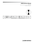
FRONT PANEL
Each channel, A and B, has LED indicators to indicate when that channel`s Gate is on.
There are three more LED status indicators;
One is marked DATA. This illuminates when the Pro-2000 mkII is receiving MIDI data.
The other two are marked PARAMETER and VALUE. These indicate which mode the Pro-2000 mkII is in,
and are toggled by the SELECT button.
Four buttons; SELECT, ENTER and INC and DEC. - These are for editing the Pro-2000 mkII.
2
* INC and DEC - scroll through parameters or values, depending on which mode the unit is in.
* SELECT - (1) toggles between Parameter and Value for editing. (2) If you hold in the SEL button for a
couple of seconds it will take you directly to the STORE or LOAD page. If something has been edited it
will take you straight to STORE otherwise it take you to LOAD. It just takes you to the page - you still
need to select the correct memory location and press Enter to perform the operation.
*ENTER - this button has 3 functions - (1) It displays the memory number from which the setup has been
loaded, and whether or not it has been edited. (2) When in system settings mode (LOAD from or
STORE to) this button will save the settings which you have entered. (3) If you hold the button in for
about 6 seconds it will perform a global all notes off and display a message to that effect on the
display. (NB this turns off all notes on the Pro-2000 mkII, it does not send any MIDI messages out of the
MIDI out port.
* 2 x 16 backlit LCD, and power switch.
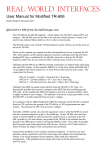
BACK PANEL
From left to right, there is the:
IEC power socket (power lead supplied).
MIDI In, Out, and Thru DIN type sockets.
Sync24 DIN socket.
Clock pulse 3.5mm minijack output.
Channel A and B CV and Gate 3.5mm minijack outputs.
The six auxiliary 3.5mm minijack outputs.
Above these is space for the optional expansion port, which (if fitted) is either a WASP/KADI
port or a DCB port .
SETTING UP YOUR Pro-2000 mkII
MIDI CONNECTIONS
MIDI IN
- connect this to the MIDI Out of your MIDI synth or MIDI sequencer using standard MIDI cables.
MIDI OUT
- connect this to the MIDI In of your MIDI sequencer or old synthesizer. This is only needed if you will be
editing the Pro-2000 mkII using SYSEX or doing MIDI data dumps, or if you are using the MIDI channel
filter.
MIDI THRU
- this provides a copy of the information coming into the MIDI In socket so that you can "daisy-chain"
several MIDI devices. It should be connected only to a MIDI In socket if needed.
ANALOGUE CONNECTIONS
CV A & B(-3 volts to +8 volts)
- the control voltage output to control the pitch of most synths, such as Roland, SCI, and Moog, Korg
and Yamaha. When using this make sure that the correct scaling is selected ie volt per octave or Hz/v.
Connect this output to the input marked CV, oscillator, KBD IN, VCO CV in, VCO, KEY Volt in, etc., of
your synth.
GATE A & B (0 to +5volts or +15 volts)
- the gate voltage output that provides the note on/off information for synths. This is used for most
synths, such as Roland, ARP, Oberheim, Moog etc.
Connect this output to the input marked Gate in, TRIG in, etc., of your synth.
3
This socket has several modes, which are selectable in software, you may have to adjust this to
receive optimum performance from your synth, as some synths require S-Trig - S-Trig is used to control
Moogs, Korgs etc.
The tip of the jack is the trigger signal - if your synth has the CINCH/JONES connector with two flat pins,
the narrower pin is the trigger signal and the wider one is ground.
AUXILIARIES 1 to 6 (-12.6 to +12.6 volts)
- a voltage output for connecting to an auxiliary input on a synth such as filter control or VCA volume.
Connect this output to the input marked VCF in, VCF fcM, Filter, etc, on your synth to control the filter
cut-off, or the input marked VCA, Volume, loudness, etc., to control volume. You could also connect
this to inputs such as portamento, pulse width, high pass filter cut-off, etc.
Cable Connections
All minijack outputs on the Pro-2000 mkII need standard 3.5mm mono minijack plug. The connection
at the synth end of course depends on what synth you are using. Kenton are able to sell you cables
for connecting to just about any synth, just visit our website.
THE ARP CLOCK & SYNC 24 OUTPUTS
CLOCK PULSE - (arpeggio clock)
- this output provides a +5 volt clock pulse related to the incoming MIDI clock. The ratio of MIDI clocks
to arpeggio pulses can be adjusted - (see CLOCK PULSE DIVIDE).
A +5 volt level will be output on the first MIDI clock after a MIDI start (or continue if selected) is
received, and thereafter dependent upon the CLOCK PULSE DIVIDE ratio.
You may for example connect this to an input marked Ext. Clock In on an analogue drum machine or
sequencer. It could also be used to gate/trigger envelopes or Sample and Hold circuits in time with
MIDI clock.
SYNC 24 - (DIN 24 sync, used on SOME ROLAND equipment)
- this output provides clock and stop/start signals. See later in the manual for pinout information.
Cable Connections
MIDI leads may not be suitable for connecting to the SYNC 24 socket as they require different pins
connected. Use a 5 pin DIN to 5 pin DIN audio lead available from Kenton (or a HI-FI shop).
Connect this output to the SYNC 24 input on a TR606/808, MC202, or TB303 to synchronize these
instruments’ sequencers to MIDI clock.
EDITING THE Pro-2000 mkII
The Pro-2000 mkII is very easy to use. It uses a standard system of editing. It has a clear and informative
2x16 LCD with backlight, INCREMENT, DECREMENT, SELECT and ENTER buttons.
To select the parameter you wish to edit, the parameter LED (the red light emitting diode), must be lit.
If it is not, press the SELECT button. You can now scroll through the parameters using the INC and DEC
buttons.
To edit a value, press the SELECT button again. The value LED will light up. Now by pressing the INC
and DEC buttons, the value can be edited.
4
To speed up editing - if you are holding the INC button and want to go faster, press the DEC button
too, this will step about twice as fast, similarly if you are holding the DEC button you can press INC to
go faster.
When you have edited parameters to your own specification, go to the “STORE to Mem#x” menu
option, where, by selecting which of seven locations you wish to use and pressing ENTER you can save
your set-up. The most recently LOADed or STOREd setup will be loaded next time you power-up. You
can get to the LOAD / STORE location quickl;y by holding the SEL button in for a couple of seconds.
PARAMETERS
THE FOLLOWING PARAMETERS ARE THE SAME FOR BOTH OF THE CV
CHANNELS, A, B (where x is the channel)
CV x SYNTH CHANNEL x (1 to 16, defaults: A=1 B=2)
- sets the MIDI receive channel for Pro-2000 mkII analogue channel.
CV x NOTE PRIORITY (low/high/newest, default: newest)
- sets the note priority.
If set to "Lowest" then the new note played takes precedence if it is lower than the preceding note.
If set to "Highest" then the new note played takes precedence if it is higher than the preceding note.
If set to "Newest" then the newest played note played takes precedence regardless.
CV x TRIGGER MODE (Single/Multiple, default: Multiple)
- sets the whether the envelope on your synth will be retriggered when a new, overlapping note is
played. If set to "Single," then the Gate output will stay on, or the trigger (if selected) will not re-trigger
when a new note is played, if you are playing in a legato fashion, with notes overlapping.
If set to "Multiple," then the Gate (or S-Trig) output will re-Gate each time a new note is played, retriggering your synth`s envelope generators, regardless of your playing style.
CV x TRANSPOSE (-24 to +24 semitones, default: 0)
- allows you to Transpose the incoming MIDI notes in semitone steps. You can adjust this in real-time,
allowing you to hear the changes you make to Transpose, without having to re-play a key.
CV x PITCHBEND (0 to 24 semitones, default: 2)
- sets the maximum range the pitchbend will bend the CV output.
CV x PORTAMENTO TYPE (fixed rate or fixed time, default: fixed rate)
- sets how the next parameter affects the portamento.
Fixed rate: the time taken to glide between notes depends on the amount of notes in the glide range.
The glide time between semitones is constant.
Fixed time: the time taken to glide between notes is the same no matter how far apart the notes are.
5
CV x PORTAMENTO RATE (or TIME) (0 to 127, default: 98)
- sets the speed at which portamento glides between notes. Note that 0 is fastest rate but does not
mean portamento off, use portamento controller (below) for that! This value can also be varied in real
time using MIDI controller number 5 (portamento time). If this parameter is in view on the display, its
new value will not be displayed when varied using controller 5. However If varied via SYSEX, the new
value will be displayed.
CV x PORTAMENTO CONTROLLER (Auto ,ON, OFF, 0-119, default: 65)
- sets the controller responsible for enabling-disabling the portamento control. If on or off are selected
these force on or off. If Auto is selected, then portamento is obtained only when you play in a legato
manner (i.e. playing the new note before releasing the old one), thus you can turn portamento on or
off, depending on how you play the notes.
CV x LFO DEPTH CONTROL (pb, vel, aft, controllers 0-119, default: #1 mod
wheel).
- assigns which MIDI controller will control the LFO depth of modulation of the CV output.
CV x LFO DEPTH AMOUNT (for controller maximum 0-127, default:65).
- allows you to set the maximum LFO depth for the CV out
CV x LFO ASSIGN Use LFO number (1 to 2, default: A=1, B=2)
- lets you assign which of the two inbuilt LFOs will modulate the CV outputs.
CV x Gate Select (default: 5v pull-up)
- you can select the following type outputs for the Gate output;
S-trig no pull-up
This would probably be used for Moogs & Korgs.
S-trig 5v pull-up
S-trig 15v pull-up
This would probably be used on the Yamaha CS range of synths instead of the Gate output.
Gate V-Trig 5v pull-up
Gate V-Trig 15v pull-up
These are the standard gates and should be used to run most synths including Roland,Arp, SCI.
CV x Fine Tune ( -127 to +127 default 0)
- Fine tunes the mono-synth.
CV x Scale ( -127 to +127 default 0)
- This is used to tune in the octave scaling of your analogue synth. Will only need adjusting if your synth
sounds out of tune as you play further up the keyboard (see `Tuning in Your Analogue Synth`). - Check
whether CV select has been set correctly (see below).
CV x CV/HZ Select ( Volt/Oct or Hz/V or 1.2V/Oct – default: Volt/Oct scaling)
- This is used to select the scaling system. Most synths will use Volt/Octave scaling, although most Korg
and Yamaha synths will require the Hz/V selection (note that the Korg Monopoly is Volt/Octave). For
the very few synths that employ 1.2V/Octave scaling (one tenth of a volt per semitone) the
1.2V/Octave mode should be selected.
6
DIGITAL OUTPUT PARAMETERS
ChC DATA FILTER MIDI Receive Channel (1 to 16, default: 3)
- sets the MIDI receive channel for the MIDI channel filter.
Only MIDI data on this channel will be retransmitted to the Pro-2000 mkII MIDI out.
It can be retransmitted on a different channel if necessary; see below.
ChC DATA FILTER MIDI Transmit Channel (1 to 16, default: 1)
- sets the channel that the MIDI data from the MIDI channel filter is retransmitted on.
This might be used to change the transmit channel of early DX7s, for instance, that can only transmit
on MIDI channel 1.
ChD EXPANSION PORT MIDI Receive Channel (1 to 16, default: 4)
- sets the MIDI receive channel for the expansion port (either DCB or WASP/KADI)
ChD EXPANSION PORT status
- tells you which port, if any, is fitted & allows you to change between KADI & WASP modes. A
standard unit will read NO PORT FITTED, however if a DCB port is present it will say DCB PORT FITTED or if
the KADI/WASP port is present it will say KADI selected or WASP selected, you can change between
the two modes using the inc & dec buttons.
-------------
Using the KADI port with your modified TR606/808
Connect the special 15 way cable supplied to the TR606 or TR808 and to the Pro-2000 mkII KADI port.
The TR606/808 can now be played from your master keyboard/sequencer. The sounds will play with or
without Accent. A velocity level of over 85 will cause the sound to be accented, subject to the level
of Accent selected on the TR606/808. KADI kits for other drum machines are now available, (including
CR8000 and CR78) contact us for details and voice mapping.
Below is the MIDI drum map for the TR-606
NOTE
C
C#1
D1
D#1
E1
F1
G1
MIDI NOTE #
36
37
38
39
40
41
42
Below is the MIDI drum map for the TR-808
NOTE
MIDI NOTE # TR-808 SOUND
TR-606 SOUND
BASS DRUM
SNARE DRUM
LOW TOM
HIGH TOM
CYMBAL
OPEN HIHAT
CLOSED HIHAT
C
C#1
D1
D#1
E1
F1
F#1
G1
G#1
A1
A#1
7
36
37
38
39
40
41
42
43
44
45
46
BASS DRUM
SNARE DRUM
LOW TOM/CONGA
MID TOM/CONGA
HI TOM/CONGA
RIMSHOT/CLAVES
CLAP/MARACAS
COWBELL
CLOSED HIHAT
OPEN HIHAT
CYMBAL
AUXILIARY OUTPUTS
THE FOLLOWING PARAMETERS ARE THE SAME FOR EACH AUXILIARY 1 TO 6
(where x is the auxiliary number)
AUX
x AUX OUTPUT x Receive channel(1to16, default: 1 to 6 set to 1 to 6
respectively)
- assigns the auxialiary to which ever MIDI channel you wish to set it to, i.e. to get the auxiliary to
respond the synth on CV channel A, set it to the same receive channel as that synth.
AUX x CONTROLLER (pb, vel, aft, controllers 1-119, V/Oct form Notes, Gate from
Notes, Trig pulse A/B - default: #16 general purpose controller)
- sets the MIDI controller source to control the analogue auxiliary output level, to control VCF, VCA
etc.
see below for details of the new modes V/Oct, Gate & Trig A/B.
AUX x OUTPUT LEVEL For cntrl Min (-64 to +64, default: 0)
- sets the auxiliary output level for when the MIDI Controller Source is at its minimum.
AUX x OUTPUT LEVEL For cntrl Max (-64 to +64, default: 64)
- sets the auxiliary output level for when the MIDI Controller Source is at its maximum.
AUX x OUTPUT LEVEL Reset Level (-64 to +64, default: 0)
- sets the level that the auxiliary will reset to when a MIDI reset command is received.
AUX x LFO DEPTH CONTROLLER (pb, vel, aft, controllers 1-119, default: #17)
- sets the MIDI controller source to control the LFO depth that will modulate the auxiliary output.
AUX x LFO DEPTH AMOUNT For cntrl Max (0-127 default: 63)
- sets the depth of the LFO at the controller maximum.
AUX x LFO ASSIGN Use LFO number (1 to 2, default: 1-3=1, 4-6=2.)
- lets you assign which of the two inbuilt LFOs will modulate the auxiliary
NEW MODES FOR AUX CHANNELS 1-6
V/Oct from Notes
- this allows the selected auxiliary output to give a CV voltage to control the CV input of a synth. Set
the MIDI receive channel of the selected auxiliary and use in conjunction with another Aux set to the
same channel but configured as a gate (see below). The MIDI channel can be any channel you
want, for any aux, it is independent of Channels A/B.
You can modulate the output using an LFO but the range default is set to be appropriate for its use as
an Aux out - we suggest you set the LFO Depth Amount to 10 or so (and probably set the controller for
it to #1 (Mod Wheel))
When using this mode, the Min value becomes the Fine-tune value, the Max value becomes Scale
and you should ensure the reset value is 0. When you want to tune the converter to your synth, first
play C note #36 (usually the bottom note on a 61 note keyboard) and use fine tune to get that right,
then play C a couple of octaves up and get that in tune using the scale adjustment. Restrictions - The
Aux outputs cannot be set to Hz/V mode, there is no portamento, sustain pedal or transpose facility,
note memory is for 2 notes only, note priority is for most recent note in multiple trigger mode.
Pitchbend range is set globally for all any auxes in CV mode using the Ax1-6 Pitchbend Range
parameter.
8
Gate from Notes
- this allows the selected auxiliary output to give a voltage output in response to notes on any MIDI
channel you select - the off and on levels can be changed by using the Min & Max (and Reset) level
controls - Min sets the voltage when the gate is off and Max sets the level when the gate is on. For
example if you set min to zero and Max to 25 you will have a 5v gate signal or if you set Min to 25 and
Max to zero you will have an S-trig with +5v pullup.
Trig Pulse A / B
(mainly used for ARP-2600 & early Odysseys)
- this allows the selected auxiliary to give a trigger pulse for synths requiring this extra signal in
addition to the normal gate signal. To use this mode, select Trig Pulse A / B on any Aux and set the
MIDI receive channel of that aux to be the same as the MIDI receive channel of the Synth Channel (A
or B) you want it to work with - set min and max to be the off an on output voltages you want to use see below for an example of connecting to an ARP-2600. NOTE the Trig Pulse A/B mode only works
in conjunction with Channels A/B.
Example of using `Trig Pulse A / B' mode of the Pro-2000 mkII with an ARP-2600 synth from CHANNEL A
for CV & Gate and Aux 1 for Trigger. The following example applies to the `Trig Pulse A / B' mode only,
it DOES NOT apply to the "V/Oct from notes" or "Gate from notes" modes.
1)
Connect CV CHANNEL A of Pro-2000 mkII to all 3 KBD CV inputs of the ARP-2600. You may need to
use the MULTIPLE 4 way socket connection to the bottom left of the ARP to do this. If the ARP
keyboard is not attached you may be able to connect using just one lead into the KBD CV
Output on the ARP (it can be used as an input if the 2600 Keyboard is not connected).
2) Ensure CvA CV/HZ Select is set to Volt/oct scaling
3) Connect GATE CHANNEL A of the Pro-2000 mkII to the GATE input of the 2600 (located above the
right speaker volume control)
4) Set CvA Gate Select to "Gate 15v pullup"
5) Connect that AUX 1 to the TRIG input of the 2600 (located next to the gate input - see above)
6) Set parameter Ax1 Main Cntrllr to "Trig Pulse A / B"
7) Set AUX 1 to the same MIDI channel as Channel A
8) Ensure that Ax1 output level for cntl Min = 0
9) Ensure that Ax1 output level for cntl Max = +63
10) Store the settings (long press on SEL will take you to store page)
11) Everything should now be ready but note the following points:The above can similarly apply to CHANNEL B and any of the AUXes 1-6 outputs if that Aux Main
Controller is set to "Trig Pulse A / B". The selected AUX output will only give a trigger signal in the `Trig
Pulse A / B' mode when it is set to the same MIDI channel as either CHANNEL A or CHANNEL B.
Ensure that any aux output which is no longer required as a trigger output, is reset to another controller
or "ignore controllers" as operation of gate A or B outputs on the same MIDI channel are affected when
`Trig Pulse A / B" is in operation.
LOW FREQUENCY OSCILLATORS
THERE ARE TWO INDEPENDENT LFOs, 1 & 2 (where x is the LFO number)
LFO x SPEED = (0 to 127, default: 80)
- sets the speed of the LFO
9
LFO x WAVESHAPE # (1 to 9 as below, default: triangle[1])
- sets the wave shape for the LFO
1, Triangle
2, Sawtooth up
3, Sawtooth down
4, Square
5, PulseWidth 10%
6, PulseWidth 20%
7,1 PulseWidth 30%
8, PulseWidth 40%
9, Sample + Hold
(random depth)
LFO x MIDI SYNC (off, 1 to 96, default: off)
- allows the LFO waveform to be synchronised to MIDI clock, with a variable divide ratio. If MIDI sync is
selected and is in operation, the 2000 will automatically recalcul;ate the LFO speed in order to fit a
whole LFO waveform between MIDI clocks (or multiples of clocks depending on the setting of sync
divide. (See below for divide ratios).
If set to 1, there will be 1 cycle of the LFO for every 1 MIDI clock. (i.e. 24 cycles per quarter note)
If set to 24, there will be 1 cycle of the LFO for every 24 MIDI clocks. (i.e. 1 cycle of the LFO per quarter
note)
Note; MIDI sends 24 clocks per quarter note.
Below is a table of values you can set the divide ratio to to obtain LFO cycles of various musical
lengths:
Note type;
Divide ratio;
Semibreve
Minim
Crotchets
Crotchet triplets
Quavers
Quaver triplets
Semiquavers
Semiquaver triplets
Demisemiquavers
Demisemiquaver triplets
96
48
24
16
12
8
6
4
3
2
SYNC and CLOCK SETTINGS
SYNC Clock Divide (1/2 &1 to 24, default: 2)
- sets the ratio of MIDI clocks to output pulses from the clock pulse output.
Note that cpqn = clocks per quarter note and that the MIDI clock rate is always 24 cpqn
If set to ½ = 48 cpqn - there will be 2 pulses from the clock pulse output for every 1 MIDI clock
If set to 1 - there will be 1 pulse from the clock pulse output for every 1 MIDI clock (24 cpqn)
If set to 24 - there will be 1 pulse from the clock pulse output for every 24 MIDI clocks (1 cpqn)
Below is a table of values you can set the divide ratio to to obtain a clock pulse at various musical
time intervals:
10
Note type;
Crotchets
Crotchet triplets
Quavers
Quaver triplets
Semiquavers
Semiquaver triplets
Demisemiquavers
Demisemiquaver triplets
Divide ratio;
24
16
12
8
6
4
3
2
CPQN
1
2
3
4
6
8
12
SYNC CLOCK Polarity: +ve/-ve clock pulse (default: +ve)
- sets the type of clock pulse sent from the clock pulse output.
Most synths, sequencers & drum machines require this to be set to +ve, but there may be a few that
require it to be set to Inverted (including the KORG MONOPOLY)
SYNC MIDI CLOCK Continue is ignored/= start (default: Continue=start)
- If set to ‘ignored’, MIDI continue messages are ignored unless immediately preceded by a ‘song
position pointer’ zero message – in which case they are automatically treated as a ‘start’. If set to
Continue=start, MIDI continue messages are always treated as if they were MIDI ‘start’ messages.
PROBLEMS YOU MAY ENCOUNTER WHEN USING MIDI CLOCK
When using the MIDI clock in conjunction with the Pro-2000 mkII please note the following. The Kenton
add-on cannot sync the arpeggio if it is not actually receiving the MIDI clock. This is not as silly as it
sounds, there are a few points to watch for:Some MIDI mergers & patch bays actually remove MIDI clock information from the MIDI data stream
or you may have to enable it for the port you are using.
Users of CUBASE note that the default for MIDI clock is for it NOT to be sent, you will have to go into
MIDI Synchronization page and select MIDI Clock to transmit.
Users of UNITOR/EXPORT on an Atari note that the MIDI clock will only come out of port A, (that is the
Atari's own MIDI port), unless you can re-assign it.
SYSTEM SETTINGS
SYSEX DEVICE NUMBER (1 to 16, default: 1)
- sets a device number for the unit in case you have more than one pro-2000 and want to control
each independantly
POLY CHAN ACTIVE (None, A+B, +Aux12,+Aux34,+Aux56, default: None)
- This setting lets you decide which synth channels are assigned for use in poly mode.
Options are:
None - All Mono (default)
A+B only
(2 voice)
A+B+Aux12
(3 voice)
A+B+Aux12+34 (4 voice)
A+B+Aux12+34+56 (5 voice)
Polyphonic mode is active when this parameter is set to anything other than "None - All Mono"
If you are using more than just channels A+B, then the Aux outputs must be used in pairs:
Aux 1 with Aux 2, Aux 3 with Aux 4, Aux 5 with Aux 6. Auxes not being polyphonically
controlled will continue to be independent. Remember to set the Auxes to CVs or Gates.
11
POLY NOTE ASSIGN (Regular Cyclic, Memory Cyclic, Reset, default: Regular Cyclic)
- This parameter sets how incoming MIDI notes are assigned to voices. This setting only has any effect
if polyphonic mode is active. Options are:
Regular Cyclic Mode (default)
Memory Cyclic
Reset Mode
Regular Cyclic Mode:
Incoming MIDI notes are assigned the next free voice. (Even if it is the same note played repeatedly).
If, for instance you have channels A+B+Aux12+34 set to poly, each time you play a note it will step
through and assign channels A then B then Aux12 then Aux34 then back to A again as you play.
If you hold a note, new notes will be assigned to the next voice in that order that is free.
If all voices are already assigned to held notes, the next note will use the lowest voice held.
Memory Cyclic:
This mode is similar to the regular cyclic mode described above. However, a new note will be
assigned to the same voice as before if that voice is not currently playing and has not been reassigned. For example if you play notes C D D C then they will be played by channels A B B A, rather
than A B Aux12 Ax34 as they would in Regular Cyclic Mode. If all voices are already assigned to held
notes, the next note will use the lowest voice held.
Reset Mode:
As you play, the lowest free voice (channel A being the lowest) is assigned to the new note.
If all voices are already assigned to held notes, the next note will use the lowest voice held.
More information about using Polyphonic Mode:
Note that if you assign any of the Auxes to be polyphonically controlled, then you will have to
configure them as either CV or Gate outputs. It is recommended that you use the odd numbered
Auxes for CV and the even numbered ones for Gate to preserve the pattern of CV followed by gate
across the back panel, however this is not essential.
In order for the Auxes to perform in a similar way to channels A and B, you will also have to
change the following parameters on the auxes which are acting as CVs (the odd numbered ones).
Ax1 LFO Dpth Ctl - set to: 1 Mod Wheel
Ax1 LFO Dpth Amt - set to: at Cntl Max 9
The same changes for auxes 3 & 5 (Ax3 & Ax5) if they are also to be polyphonically controlled.
This is so that use of the mod wheel will be the same as for channels A and B.
Change the following parameters on the auxes acting as Gates (the even numbered ones).
Ax2 LFO Dpth Ctl - set to: Ignore Cntrllers
The same changes for auxes 4 & 6 (Ax4 & Ax6) if they are also to be polyphonically controlled.
This is so that the gate outputs will not be modulated too.
When a channel (or pair of Aux outputs) is assigned as polyphonic, it becomes a slave to Channel A
and takes its MIDI channel from Channel A.
In Polyphonic Mode - Note priority for any active polyphonic channels is always set by the "Poly Note
Assign" parameter. Individual channel note assignments are overridden.
You may also need to set the Gate Voltage (and/or gate polarity) of any auxes used in poly mode
12
STORE TO MEMORY (Memory #1 to 24, default: 1)
- having changed all the parameters to suit your setup, you can use this option to save these settings
to one of 24 memories, for use within different configurations.
LOAD FROM MEMORY (Memory #1 to 24, default: 1)
- allows you to load from one of the 24 memories into the unit.
With both of the above two parameters, you need to select Value edit and use the INC & DEC buttons
to select the memory you want to load from or store to.
When you have loaded from or stored to a memory location, the Pro-2000 mkII will treat that as the
current location and load from it on power up. If you hold in the SEL button for a couple of seconds it
will take you straight to the STORE or LOAD page depending on whether anything has been edited.
PRESETS [in memory locations 15 to 24]
As supplied, or after a full reset, presets 1 to 14 are all loaded with the default setup for use with an SH-101.
This setup is suitable for a lot of other standard CV / Gate synths too. The following presets for other synths are
loaded into the locations shown. See above for how to load setups. Presets 19 to 24 only set up Channel A.
It is recommended that you copy any preset you want to use to another unused location and then edit that
duplicate copy (for tuning etc.)
The polyphonic setups are included because there are quite a few settings to change when using the Aux
channels as CVs & Gates, in fact you can use presets 15 to 17 to set up the Auxes as CVs & Gates – just load
the preset, then turn poly mode off.
Prog
#24
#23
#22
#21
#20
#19
#18
#17
#16
#15
Synth
Roland SH-09 (also Moog Prodigy mk1 with KE skts)
Minimoog
Other Moog
Korg MS-20
Yamaha CS-10
ARP2600 (also Odyssey mk1+KE skts)
2 note poly A+B
3 note poly A+B+Aux12
4 note poly A+B+Aux12+34
5 note poly A+B+Aux12+34+56
Changes from default (SH-101) setup
Gate 15V
S-trig, coarse tune –5 semitones
S-trig, coarse tune zero
S-trig, Hz/V
S-trig with 5V pullup, Hz/V
Gate 15V, Aux1 set to TRIG
None
None
None
None
MIDI DIAGNOSTICS MODE
The Pro-2000 mkII has a built-in MIDI analyser function. This feature allows you to see what types of MIDI
messages are being transmitted by your master keyboard/sequencer, making the PRO 2000 a useful
diagnostic tool, which can help you when you have a problem with your MIDI set-up.
To enter analyser mode, you must power on the PRO 2000 whilst holding the SELECT button. The
display will then show ‘CHANnel’, ‘NOTE#’ and ‘VELOCity’, and will display the relevant data, below
the heading. Using the INC, DEC, SELECT and ENTER buttons, different types of MIDI messages received
may be displayed as follows:SELECT
DEC
INC
ENTER
rec’d.
Short press
Short press
Short press
Long press
Short press
CLock,STATUS and SYSEX data received for checking MIDI clock.
CHANnel,NOTE# and VELOCity as above, note information.
CHANnel,CONTroller# and VALUE displays controller information.
CONTROLLER IDENTity - displays the name of the rec’d controller.
CHANnel,PROG# and BANK# - displays program change as
Although pitchbend and after-touch are not strictly controllers, they will be identified and treated as if
they are controllers for the purposes of the analyser mode.
13
Pro-2000 mkII SYSEX INFORMATION
The first five bytes of sysex for the Pro-2000 mkII are always the same for all data types
[
[
[
[
[
1]
2]
3]
4]
5]
0F0h
00h
20h
13h
02h
- Sysex command
- Company ident first byte
- Company ident second byte
- Company ident third byte
- Product code (pro-2000)
[ 6 ] 0ddd0000 - where ddd is data type
if ddd = 100 = memory dump
if ddd = 010 = data change
if ddd = 001 = dump request
(40h)
(20h)
(10h)
------------------------------------------------------------------ddd = 001 = dump request
[ 7]
[ 8]
000bbbbb - where bbbbb = block requested - valid are 0 - 24
0F7h - end of exclusive
The Pro-2000 mkII responds with a memory dump of the block requested
n.b. block 0 is the current setup, blocks 1 – 24 are the stored memory locations
Example of dump request for memory #7:
F0 00 20 13 02 10 07 F7
------------------------------------------------------------------ddd = 010 = data change
[ 7]
[ 8]
[ 9]
[ 10 ]
[ 11 ]
0000uuuu - where uuuu = low 4 bits of parameter address
0000hhhh - where hhhh = high 4 bits of parameter address
0000uuuu - where uuuu = low 4 bits of data
0000hhhh - where hhhh = high 4 bits of data
0F7h - end of exclusive
The Pro-2000 mkII responds by changing the specified data and updating the
display if necessary. - See below for parameter addresses. Examples given after parameter list.
------------------------------------------------------------------ddd = 100 = memory dump
[ 7 ] 000bbbbb - where bbbbb = block requested - valid are 0 – 24 (*see below)
[ 8 ] 0nnnnnnn - where nnnnnnn = number of bytes in dump
[ 9 ] 0000uuuu - where uuuu = low 4 bits of data
[ 10 ] 0000hhhh - where hhhh = high 4 bits of data
Bytes 9 & 10 are repeated the number of times specified in 8
[ 11 ]
0F7h - end of exclusive
The Pro-2000 mkII will send the above data when requested by the sysex
dump request listed above.
When memory dump data are sent to the 2000 the following will happen:* If the dump specifies block 0 (current setup) the data will be immediately utilised and the display will be updated. If the dump specifies
any other block (a stored memory location) the dump will be sent to the
14
specified memory location and also to the edit buffer (current setup)
the data will be immediately utilised and the display will be updated.
You may change the block number of a memory dump without causing any
problem. For example, data that came from memory 6 could be returned to
the current setup by merely changing the 06 in byte [ 7 ] to a 00.
Parameter data are stored in the following addresses.
Function
Range
Notes (see end)
00h
01h
02h
03h
04h
05h
06h
07h
08h
09h
0Ah
0Bh
0Ch
0Dh
A Receive chan
A note priority
A trig / retrig
A transpose
A pitchbend range
A portamento speed
A portamento cont #
A lfo depth controller #
A lfo max val
A lfo assign
A gate select
A fine tune val
A scale val
A v/o – hzv – 1.2v select
0 - 15
0-2
0-1
232 > 0 > 24
0 - 24
0 - 255
252 - 0 - 119
252 - 0 - 119
0 - 127
0-1
0-7
129 > 0 > 127
129 > 0 > 127
0-2
{1}
0Eh
0Fh
10h
11h
12h
13h
14h
15h
16h
17h
18h
19h
1Ah
1Bh
B Receive chan
B note priority
B trig / retrig
B transpose
B pitchbend range
B portamento speed
B portamento cont #
B lfo depth controller #
B lfo max val
B lfo assign
B gate select
B fine tune val
B scale val
B v/o – hzv – 1.2v select
0 - 15
0-2
0-1
232 > 0 > 24
0 - 24
0 - 255
252 - 0 - 119
252 - 0 - 119
0 - 127
0-1
0-7
129 > 0 > 127
129 > 0 > 127
0-2
1Ch
1Dh
1Eh
1Fh
C Receive chan
C Transmit chan
D Receive chan
D kadi / wasp select
0 - 15
0 - 15
0 - 15
0-1
{1}
{1}
{1}
20h
21h
22h
23h
24h
25h
26h
27h
Ax1 Receive chan
Ax1 Cont #
Ax1 min val / fine tune
Ax1 max val / scale
Ax1 reset val
Ax1 lfo cont #
Ax1 lfo max val
Ax1 lfo assign
0 - 15
239 > 0 > 119
0 > 64 > 127
0 > 64 > 127
0 > 64 > 127
252 - 0 - 119
0 - 127
0-1
{1}
{6}
{5}
{5}
{5}
{4}
28h
29h
2Ah
Ax2 Receive chan
Ax2 Cont #
Ax2 min val / fine tune
0 - 15
239 > 0 > 119
0 > 64 > 127
{1}
{6}
{5}
Address
15
{2}
{3}
{4}
5 modes used
129>0 = -ve
129>0 = -ve
{1}
{2}
{3}
{4}
5 modes used
129>0 = -ve
129>0 = -ve
2Bh
2Ch
2Dh
2Eh
2Fh
Ax2 max val / scale
Ax2 reset val
Ax2 lfo cont #
Ax2 lfo max val
Ax2 lfo assign
0 > 64 > 127
0 > 64 > 127
252 - 0 - 119
0 - 127
0-1
{5}
{5}
{4}
30h
31h
32h
33h
34h
35h
36h
37h
Ax3 Receive chan
Ax3 Cont #
Ax3 min val / fine tune
Ax3 max val / scale
Ax3 reset val
Ax3 lfo cont #
Ax3 lfo max val
Ax3 lfo assign
0 - 15
239 > 0 > 119
0 > 64 > 127
0 > 64 > 127
0 > 64 > 127
252 - 0 - 119
0 - 127
0-1
{1}
{6}
{5}
{5}
{5}
{4}
38h
39h
3Ah
3Bh
3Ch
3Dh
3Eh
3Fh
Ax4 Receive chan
Ax4 Cont #
Ax4 min val / fine tune
Ax4 max val / scale
Ax4 reset val
Ax4 lfo cont #
Ax4 lfo max val
Ax4 lfo assign
0 - 15
239 > 0 > 119
0 > 64 > 127
0 > 64 > 127
0 > 64 > 127
252 - 0 - 119
0 - 127
0-1
{1}
{6}
{5}
{5}
{5}
{4}
40h
41h
42h
43h
44h
45h
46h
47h
Ax5 Receive chan
Ax5 Cont #
Ax5 min val / fine tune
Ax5 max val / scale
Ax5 reset val
Ax5 lfo cont #
Ax5 lfo max val
Ax5 lfo assign
0 - 15
239 > 0 > 119
0 > 64 > 127
0 > 64 > 127
0 > 64 > 127
252 - 0 - 119
0 - 127
0-1
{1}
{6}
{5}
{5}
{5}
{4}
48h
49h
4Ah
4Bh
4Ch
4Dh
4Eh
4Fh
Ax6 Receive chan
Ax6 Cont #
Ax6 min val / fine tune
Ax6 max val / scale
Ax6 reset val
Ax6 lfo cont #
Ax6 lfo max val
Ax6 lfo assign
0 - 15
239 > 0 > 119
0 > 64 > 127
0 > 64 > 127
0 > 64 > 127
252 - 0 - 119
0 - 127
0-1
{1}
{6}
{5}
{5}
{5}
{4}
50h
Ax1-6 pb range
0 - 24
51h
52h
53h
Lfo1 speed
Lfo1 waveshape
Lfo1 sync
0 - 127
0-8
0 - 96
{7}
{8}
54h
55h
56h
Lfo2 speed
Lfo2 waveshape
Lfo2 sync
0 - 127
0-8
0 -96
{7}
{8}
57h
58h
59h
arp clk div
arp clk polarity
cont = start
0 - 23
0-1
0-1
{9}
{ 10 }
{ 11 }
5Ah
5Bh
5Ch
5Dh
Poly Chan Active
Poly Note Assign
A portamento type
B portamento type
0-4
0 / 10h / 20h
0-1
0-1
0=mono, 1=2chans, 4=5chans
{ 12 }
0=rate, 1=time
0=rate, 1=time
16
{ NOTES }
{ 1 } Data 0 - 15 corresponds to MIDI channels 1 - 16
{ 2 } 232 = -24 semitones 0 = no transpose 24 = + 24 semitones - 25 to 231 are invalid
{ 3 } 252=auto pmt 253=pmt off 254=pmt on 255=prg chng & 0 - 119
{ 4 } 252=ignore 253=pitchbend 254=velocity 255=aftertouch & 0 - 119
{ 5 } 0= -64 64=0 127=+63
{ 6 } 249=gate 250=v/oct 251=trig a/b 252=ignore 253=p.bend 254=vel 255=aft & 0 - 119
{ 7 } 0= triangle 1= saw up 2= saw down 3= 10% pulse etc. as display
{ 8 } 1 - 96 corresponds to sync divide 1 to 96 and 0 = off
{ 9 } 0 - 23 corresponds to arpeggio divide 1 to 24
{ 10 } 0=positive 1=negative
{ 11 } 0 = continue ignored 1 = continue=start
{ 12 } 0 = Regular Cyclic, 10h = Memory Cyclic, 20h = Reset Mode
All sysex addresses and data are range checked and out-of-range values
will either be ignored or adjusted to give a valid response.
Example SysEx string to change channel A to Hz/V scaling:
Example SysEx string to change channel D to MIDI channel 16:
F0 00 20 13 02 20 0D 00 01 00 F7
F0 00 20 13 02 20 0E 01 0F 00 F7
PIN OUTS FOR DCB/WASP Pro-2000 mkII CABLES
Juno 60 (and some Jupiter 8s) connector
14 way IEEE plug (viewed from terminals).
7
6
5
4
3
2
1
14
13
12
11
10
9
8
PIN 1 - Busy
PIN 2 - Data
PIN 3 - Clock PIN 4 - Ground
No other pins connected. Insulate the screen at this end.
Other Jupiter 8s connectors
20 pin bump polarised socket (viewed from terminals).
2
4
6
8
10
12
14
16
18
20
1
3
5
7
9
11
13
15
17
19
PIN 7 - Clock
PIN 9 - Data
PIN 10 - Ground
PIN 11 - Busy
As this header is an IDC type you will need to put a 6 inch length of 16 way IDC
ribbon cable in the header, then join the cables.
Wasp connector (Wasp end of cable)
6
7
5
1
4
2
7 pin DIN plug (viewed from terminals).
1
Keyboard Data (least significant bit) (0)
2
Keyboard Data (Next significant bit) (1)
3
Keyboard Data (Next significant bit) (2)
4
Keyboard Data (Next significant bit) (3)
5
Keyboard Data (Next significant bit) (4)
6
Keyboard Data (Most significant bit) (5)
7
Note on trigger
3
17
Pro-2000 mkII KADI/Wasp Connector; (Pro-2000 mkII end of cable)
15 way high density D plug (viewed from terminals).
5
4
10
15
3
9
14
2
8
13
1
7
12
6
11
Wasp wiring;
1
2
3
4
Kybd Data (least significant bit) (0) 5
Kybd Data (Next significant bit) (4)
Kybd Data (Next significant bit) (1) 6
Kybd Data (Most significant bit) (5)
Kybd Data (Next significant bit) (2) 7
NC
(No Connection)
Kybd Data (Next significant bit) (3) 8
Note-On Trigger
screen all remaining wires, (insulate screen).
Pro-2000 mkII DIN sync port connections:
5 pin 180 degree DIN connector
Pin 1 - Stop = 0 volts Start = +5 volts (or continue if selected)
Pin 3 - 5 volt pulses; 24 clocks (pulses) per quarter note, the same as MIDI
Pin 2 - Ground (zero volts)
Pins 4 & 5 are not used.
CONNECTING YOUR MODIFIED TB303 (5 SOCKET RETRO)
TO THE Pro-2000 mkII
Pro-2000 mkII
CV CHANNEL A
GATE CHANNEL A
AUX1
AUX2
AUX3
to
TB303
>
>
>
>
>
CV IN
GATE IN
FILTER
SLIDE
ACCENT
Set the AUX sources to which ever MIDI controller you wish to control the Filter, Accent or Slide, and
link them all to CV channel A (or which ever you are using).
Using Slide;
The AUX2 controller range should be set to 0 minimum, and 50 maximum. Reset value should be 0. To
turn the SLIDE on/off, the MIDI controller must be set to 65 for on, and 0 for off. When the slide is on, all
following notes will glide into each other. It is best to play legato style for good results.
Using Accent;
The AUX3 controller range should be set to 0 minimum, and 50 maximum. Reset value should be 0. To
turn the ACCENT on/off, the MIDI controller must be set to 65 for on, and 0 for off.
18
MIDI Controller Numbers (for reference)
Controller Number
Decimal
0
1
2
3
4
5
6
7
8
9
10
11
12-15
16-19
20-31
32-63
64
65
66
67
68
69
70-79
80-83
84-90
91
92
93
94
95
96
97
98
99
100
101
102-119
120-127
Hex
00H
01H
02H
03H
04H
05H
06H
07H
08H
09H
0AH
0BH
0C-0FH
10-13H
14-1FH
20-3FH
40H
41H
42H
43H
44H
45H
46-4FH
50-53H
54-5AH
5BH
5CH
5DH
5EH
5FH
60H
61H
62H
63H
64H
65H
66-77H
78-7FH
Control Function
Bank switch MSB
Modulation wheel/lever
Breath controller
Undefined
Foot controller
Portamento time
Data entry MSB
Main volume
Balance
Undefined
Pan
Expression controller
Undefined
General purpose controllers (1-4)
Undefined
LSB for values 0-31
Damper pedal (sustain)
Portamento
Sostenuto
Soft pedal
Undefined
Hold 2
Undefined
General purpose controllers (5-8)
Undefined
External effects depth
Tremolo depth
Chorus depth
Celeste (detune) depth
Phaser depth
Data increment
Data decrement
Non-registered parameter number LSB
Non-registered parameter number MSB
Registered parameter number LSB
Registered parameter number MSB
Undefined
Reserved for channel mode messages
19
SPECIFICATIONS
Power;
230v AC 50Hz (170v - 260v) or 115v AC 50/60Hz (85v - 130v) - See note below.
6 Watts
Dimensions;
280mm x 132mm x 42mm
Weight;
2.5Kg
CONNECTIONS
Inputs;
Power Socket
MIDI In
4 push buttons
(3 pin IEC)
(5 pin 180 degree DIN type)
Outputs;
MIDI Out, Thru
Sync24
Clock Pulse
6 Auxiliaries
2 Control Voltage outputs
2 Gate outputs
Expansion port - optional
LCD 2x16 backlit
5 LED indicators
(5 pin 180 degree DIN type)
(5 pin 180 degree DIN type)
(3.5mm mono minijack)
(3.5mm mono minijack)
(3.5mm mono minijack)
(3.5mm mono minijack)
(15 pin High Density D or 8 pin Mini Din)
Accessories;
Operating Manual, Power cable
Optional Accessories; DCB port with cable (either 14 pin IEEE or 20 pin bump polarised)
KADI/WASP port with cable (either KADI or WASP cable)
Pair of ears for rack mounting
Note
The Kenton Electronics Pro-2000 mkII MIDI-CV converter has a built in mains transformer factory set to 230 volts AC 50Hz unless
otherwise marked. There is an internal switch to select 115 volts AC if required. Ensure that this adjustment is made by
competent service personnel only.
Warranty
The Pro-2000 mkII comes with a 12 month (from purchase date) back-to-base warranty, (i.e. customer must arrange and pay
for carriage to and from Kenton Electronics).
www.kentonuk.com
Kenton Electronics Limited
Brookfarm House, Station Road, South Wimbledon, London, SW19 2LP, UK
Tel: +44 (0)20 8544 9200
Fax: +44 (0)20 8544 9300
version #5240
e. & o. e.
20
21st October 2013