1
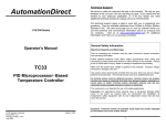
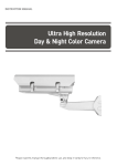
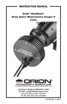
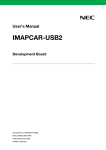
User's Manual
CV-A55 IR
1/2” Interlaced scan
Near Infrared Camera
Document Version: 1.0
Camera Revision: A
CV-A55 IR
Notice
The material contained in this manual consists of information that is proprietary to JAI Ltd.,
Japan and may only be used by the purchasers of the product. JAI Ltd., Japan makes no
warranty for the use of its product and assumes no responsibility for any errors which may
appear or for damages resulting from the use of the information contained herein. JAI Ltd.,
Japan reserves the right to make changes without notice.
Company and product names mentioned in this manual are trademarks or registered trademarks
of their respective owners.
Warranty
For information about the warranty, please contact your factory representative.
Certifications
CE compliance
As defined by the Directive 2004/108/EC of the European Parliament and of the Council, EMC
(Electromagnetic compatibility), JAI Ltd., Japan declares that CV-A55 IR complies with the
following provisions applying to its standards.
EN 61000-6-3 (Generic emission standard part 1 )
EN 61000-6-2 (Generic immunity standard part 1)
FCC
This equipment has been tested and found to comply with the limits for a Class B digital device,
pursuant to Part 15 of the FCC Rules. These limits are designed to provide reasonable protection
against harmful interference in a residential installation. This equipment generates , uses and
can radiate radio frequency energy and, if not installed and used in accordance with the
instructions, may cause harmful interference to radio communications. However, there is no
guarantee that interference will not occur in a particular installation. If this equipment does
cause harmful interference to radio or television reception, which can be determined by turning
the equipment off and on, the user is encouraged to try to correct the interference by one or
more of the following measures:
- Reorient or relocate the receiving antenna.
- Increase the separation between the equipment and receiver.
- Connect the equipment into a outlet on a circuit different from that to which the receiver is
connected.
- Consult the dealer or an experienced radio/TV technician for help.
Warning
Changes or modifications to this unit not expressly approved by the party responsible
for FCC compliance could void the user’s authority to operate the equipment.
-1-
CV-A55 IR
- Contents 1.
2.
3.
4.
5.
General......................................................................................................... 4
Camera Composition ......................................................................................... 4
Main Features ................................................................................................. 4
Locations and Functions ..................................................................................... 5
Pin Assignment ................................................................................................ 6
5.1. 12-pin Multi-connector (DC-IN/VIDEO OUT, EXT.HD/VD IN) .................................... 6
5.3. Input and Output Circuits ............................................................................ 7
5.3.1. Video output ..................................................................................... 7
5.3.2. VINT, Integration input . ....................................................................... 7
5.3.3. HD and VD input ................................................................................. 7
5.3.4. HD, VD, PCLK, SYNC output ................................................................... 7
6. Functions and Operations ................................................................................... 8
6.1. Basic functions ......................................................................................... 8
6.2. CCD accumulation .................................................................................... 8
6.2.1. Field accumulation ............................................................................. 8
6.2.2. Frame accumulation ........................................................................... 9
6.2. CCD sensor layout and full Image format .................................................... 9
6.3. Input-output of HD/VD Signals..................................................................... 10
6.4. Continuous Operation (Non triggered) ........................................................... 11
6.3.1. Timing chart for EIA ......................................................................... 11
6.3.1a Horizontal timing ........................................................................... 11
6.3.1b Vertical Timing .............................................................................. 12
6.3.2. Timing chart for CCIR ........................................................................ 12
6.3.2a Horizontal Timing ........................................................................... 12
6.3.2b Vertical Timing .............................................................................. 13
6.4. External Trigger Modes ............................................................................. 13
6.5. Edge Pre-select Mode ............................................................................... 14
6.5.1. EIA .............................................................................................. 14
6.5.2. CCIR ............................................................................................ 15
6.6. Pulse Width Control Mode .......................................................................... 16
6.6.1. EIA .............................................................................................. 16
6.6.2. CCIR ............................................................................................ 17
6.7. Frame-delay read out Mode ........................................................................ 18
6.7.1. EIA .............................................................................................. 18
6.7.2. CCIR ............................................................................................ 19
6.5. Integration Mode ..................................................................................... 20
7. Configuring the Camera ................................................................................... 21
7.1. DIP switch locations ................................................................................. 21
7.1.1. Rear Switch. ....................................................................................... 21
7.1.2. DIP switches inside ......................................................................... 21
7.2. Configuring the camera operation ............................................................... 22
7.2.1. Rear switch SW-1 ............................................................................ 22
7.2.2. 12P connector configuration............................................................... 23
7.2.3. Termination setting for HD, VD and VINT ................................................ 23
8. External Appearance and Dimensions ................................................................... 24
9. Specifications ............................................................................................... 25
9.1. Specification table ............................................................................. 25
9.2. Spectral Sensitivity .................................................................................. 26
10. Appendix ................................................................................................... 27
10.1. Precautions .......................................................................................... 27
10.2. Typical Sensor Characteristics ................................................................... 27
10.3. Caution when mounting a lens on the camera ................................................ 27
-2-
CV-A55 IR
10.4. Exportation ......................................................................................... 27
10.5. References .......................................................................................... 28
11. User's Record.............................................................................................. 29
-3-
CV-A55 IR
1. General
The CV-A55 IR is a 1/2 inch monochrome interlace scan CCD camera with EIA (RS-170) standard
video output or with CCIR video standard output. The CV-A55 IR uses a CCD with 768(H) x 494(V)
effective pixels for EIA version and 752(H) x 582(V) effective pixels for CCIR version. Both CCDs
have an extended spectrum response in the Near Infrared (NIR) area.
The CV-A55 IR uses both external and internal DIP switches to configure the camera in various
operating modes. Both cameras have three trigger modes, pre-select, pulse width and frame
delay, and can be operated using internal or external synchronization.
Both cameras also offer flange back adjustment.
These cameras are suitable for a wide range of applications within factory automation.
The latest version of this manual can be downloaded from: www.jai.com
For camera revision history, please contact your local JAI distributor.
2. Camera Composition
The standard camera composition consists of:
CV-A55 IR E Camera body(EIA version)
Or
CV-A55 IR C Camera body(CCIR version)
x 1
C-mount protection cap
x 1
Options
AC power adaptor
Tripod plate
x 1
PD-12U series
MP-40
3. Main Features
•
•
•
•
•
•
•
•
•
•
•
•
•
1/2 inch Interlaced CCD for EIA or CCIR video standard
768 (h) x 494 (v) for EIA and 752 (h) x 582 (v) for CCIR
Extended spectrum response in Near Infrared (NIR)area
High S/N ratio >56 dB
570 TV lines resolution
Gain control range from – 3dB to +24 dB
Shutter speeds from 1/100 to 1/10,000 second in 7 steps in continuous mode
1.0 or 0.45 gamma can be selected
Internal or external synchronization using HD/VD
Edge pre-select, pulse width control and frame delay trigger modes
Field accumulation or frame accumulation can be selected
Integration mode for long time exposure
C-mount with adjustable back focus
-4-
CV-A55 IR
4. Locations and Functions
⑥ ⑦
③
③
⑧
⑨
⑨
④
①②
1
2
3
4
5
6
7
8
9
Lens mount
CCD sensor
Flange back adjust pin
BNC connector
12P connector
Gain control potentiometer
DIP switch
Protection cover
Camera mounting holes
C-mount (Note *1)
1/2 inch CCD sensor
Fix these two screws after adjusting Flange back
Video output
DC+12V, trigger and pulses input
Control video gain
Configure the camera operation
Protect DIP switch and Gain potentiometer
10 x M3 4mm depth holes for mounting tripod plate
(Note*2)
*1) Note: Rear protrusion on C-mount lens must be less than 10.0mm.
*2) Note: The tripod plate is MP40 (option).
Fig. 1. Locations.
-5-
⑤
CV-A55 IR
5. Pin Assignment
5.1. 12-pin Multi-connector (DC-IN/VIDEO OUT, EXT.HD/VD IN)
Type: HR10A-10R-12PB-01 (Hirose) male
Plugs for cable: HR10A-10P-12S
9
1
2
8
10
11
3
4
7
12
6
5
Seen from the rear
Fig. 2. 12-pin connector.
Pin no.
1
2
3
4
5
6
7
8
9
10
11
12
I/O
I
O
I/O
I/O
I/O
I
Signal
GND
+12 V DC input
GND
Video output
GND / NC
VINIT / HD IN / SYNC OUT
VD IN/ CLK OUT / VD OUT
GND
HD IN / VNIT / HD OUT
NC
NC / Integration
GND / NC
Remarks
Note 1)
Note 2 )
Note 2 )
Note 2 )
Note 2 )
Note 2 )
Note 2 )
Note 1: This video output is parallel with BNC output
Note 2 : The selection of signals is done by internal switches. Refer to Chapter 7
The following table shows the factory default settings.
Pin no.
5
6
7
9
11
12
I/O
I
I
I
I
Signal
GND
VINIT
VD IN
HD IN
NC
GND
-6-
CV-A55 IR
5.2. Input and Output Circuits
The following sections show the principles for the input and output circuits for video and timing.
5.2.1. Video output
The video output on the BNC connector is a 75 Ω DC
coupled circuit. The video black DC level is 0.0 volt.
Pin #4 on the 12-pin connector is in parallel with the
BNC connector. Avoid double termination.
#4/12
+
2μ7
68
Video
Output
BNC
-
0.0 V
DC level
82p
GND
Fig. 3. Video output.
5.2.2. VINT, Integration input .
Trigger input level and Integration level are TTL,
negative polarity.
The trigger-input can be terminated by SW505.
Fig. 4. Trigger input.
5.2.3. HD and VD input
The input circuit for external HD and VD signals are
shown. It can be 75 Ω terminated by SW504.
HD and VD input level is 4 V ±2 V.
Fig. 5. HD and VD input.
5.2.4. HD, VD, PCLK, SYNC output
Output circuit for these signals are emitter followers.
It will deliver a full TTL signal.
Output level is 4 V and for PCLK, it is 3V.
Fig. 6. HD, VD, PCLK, and SYNC output.
-7-
CV-A55 IR
6. Functions and Operations
6.1. Basic functions
The CV-A55 IR camera is an interlaced scan camera. The video output is an analogue output
complying with the EIA standard for CV-A55 IR E and CCIR standard for CV-A55 IR C.
The CV-A55 IR can be configured using external and internal DIP switches for various operating
modes. For the details, refer to Chapter 7.
CV-A55 IR employs a preset shutter.
The steps for the shutter are:
CV-A55 IR E OFF(1/60), 1/100, 1/250, 1/500, 1/1000, 1/2000, 1/4000, 1/10000
CV-A55 IR C OFF(1/50), 1/100, 1/250, 1/500, 1/1000, 1/2000, 1/4000, 1/10000
Both cameras have field and frame accumulation.
Operation modes are:
1. Continuous mode
2. Edge pre-select trigger mode (EPS)
3. Pulse width control trigger mode (PWC)
4. Frame delay readout mode (FDR)
5. Integration mode
The details are described in the following chapters.
6.2. CCD accumulation
6.2.1. Field accumulation
This is the default setting of the CV-A55 IR.
It scans two horizontal rows together and charges the pair at each interline scanning. This mode
has an advantage when the shutter is often used, as the sensitivity of the CCD is doubled for one
field of integration (for shutter, integration can not exceed one field) therefore, it can obtain
the same sensitivity as the frame accumulation mode for half of the period.
Because the scanning alternates between two rows, Moiré is almost unnoticeable and even
though the vertical resolution is not as good as in frame accumulation mode, it is sufficient to
see the full vertical resolution of the TV format. Field mode cannot provide full frame resolution
with a strobe lighting application.
Fig.7. Field accumulation principle
-8-
CV-A55 IR
6.2.2. Frame accumulation
Frame accumulation scans each horizontal row as in interlace scanning. During frame
accumulation mode, integration of each pixel is one frame rate (1/30s=33ms for EIA, 1/25s=40ms
for CCIR). Vertical pixel resolution is good and exact location is obtained.
For strobe lighting, it is recommended to use frame accumulation in order to achieve full frame
resolution.
Fig.8. Frame accumulation principle
6.3. CCD sensor layout and full Image format
1
2
Dummy *1)
OB
Effective Pixels
509
/
597
768(h) x 494 (v) for CV-A55 IR E
752(h) x 582 (v) for CV-A55 IR C
494
/
582
12
OB
910 pixels /908 pixels/ line
22
Dummy
3
768 / 752
OB
Fig. 9. CCD sensor layout
-9-
40
77 /91
OB
Brank
*1) Only for
Even field
CV-A55 IR
6.4. Input-output of HD/VD Signals
In the default setting the camera will accept external HD/VD signals on pin 7 and 9 of the 12 pin
Hirose connector. If external HD/VD is applied, the camera will auto detect and synchronize to
it. If no external sync signals are applied, the camera will operate with its internal x-tal
controlled sync. The input is TTL level as factory setting. It can be 75 Ohm terminated by the
internal switch SW504.
To output the internal HD/VD signals on pin 7 and 9 the internal switch SW501 and SW502 should
be set ON. The output is TTL level from a 75-Ohm source.
7 pin
9 pin
VD IN
/CLK OUT
/VD OUT
HD IN
/VINT
/HD OUT
VD IN
CLK OUT
VD OUT
HD IN
VINT
HD OUT
SW501
SW502
Important notes on using this mode
• External sync system should follow the camera scanning.
• External HD and VD relationship should be followed as described below.
Ext. VD
Ext. HD
Less 55 μs
More 0.5μs
Fig. 10. Ext. HD and ext. VD phase conditions.
- 10 -
CV-A55 IR
6.4. Continuous Operation (Non triggered)
The camera runs continuously at 1/60s (CV-A55 IR E) or 1/50s (CV-A55 IR C) to output continuous
images. The CCD accumulation is available in either Field or Frame accumulation mode.
This is suitable for any application which does not require a trigger for image capture.
The shutter will work in all 8 steps up to 1/10,000 second.
Important notes on using this mode
• External sync system should follow the camera scanning system.
6.4.1. Timing chart for EIA
6.4.1a Horizontal timing
Fig. 11. Horizontal timing for EIA
- 11 -
CV-A55 IR
6.4.1b Vertical Timing
CV-A55 IR EIA 2:1 Interlace Vertical Timing Chart
EVEN
ODD
Int. VD
Int. HD
SYNC
CCD OUT
489
490
491
492
493
494
2
3
1
Ef f ect i ve Li ne
4
5
6
7
8
9
10
11
12
13
Ef f ect i ve Li ne
20H
Video
ODD
EVEN
Int. VD
Int. HD
SYNC
CCD OUT
490
491
492
493
494
1
2
Ef f ect i ve Li ne
3
4
5
6
7
8
9
10
11
12
Ef f ect i ve Li ne
20H
Video
Fig. 12 Vertical timing for EIA
6.4.2. Timing chart for CCIR
6.4.2a Horizontal Timing
CV-A55 IR Horizontal Timing Chart
1ck = 71ns
1 Horizontal Period
908
126
I nt . HD
Stopping Period of
5
Dummy
Horizontal Transfer
OB
40
91
22
19
Effective Pixels of Video Output
738
752
20
19
1
752
OB40
Effective Pixels
752
OB6
OB5
OB1
OB3
OB1
D22
D1
OB40
OB6
OB5
OB1
CCD out
OB
3
5
35
Horizontal Blanking Period
170
Video out
Effective Image Period
22
68
738
Fig. 13. Horizontal timing for CCIR
- 12 -
22
CV-A55 IR
6.4.2b Vertical Timing
CV-A55 IR CCIR 2:1 Interlace Vetical Timing Chart
ODD
EVEN
Int. VD
Int. HD
SYNC
CCD OUT
581
582
2
3
1
Eff ecti ve Li ne
4
5
6
7
8
9
25H
10
11
12
13
Ef fecti ve Li ne
Video
EVEN
ODD
Int. VD
Int. HD
SYNC
CCD OUT
58 2
1
2
25H
Eff ecti ve Li ne
3
4
5
6
7
8
9
10
11
12
Ef fecti ve Li ne
Video
Fig. 14. Vertical timing for CCIR
6.5. External Trigger Modes
This camera has 4 external asynchronous trigger modes, which can be set by rear-panel
switches.
1.
2.
3.
4.
Edge pre-select mode
Pulse width control mode
Frame delay read out mode
Integration mode
Pre-selected exposure
Pulse width controlled exposure.
PWC exposure read out by ext. VD.
Integration time is set by 1 VD increment
The accumulation is HD synchronous accumulation. The accumulation starts at the first HD after
the trigger leading edge. To avoid the <1H jitter caused by this delay, synchronize the external
trigger falling and rising edge to HD as shown in fig. 15 below. The trigger level translations
should be placed inside a 2 x 4.4 μseconds region as shown.
Fig.15. Ext. trigger and Ext. HD relation
- 13 -
CV-A55 IR
6.5.1. Edge Pre-select Mode
The exposure starts at the first HD pulse after the trigger leading edge. It stops and is read out
after the duration of the shutter time selected. It can be set to one of 8 steps. An EEN pulse will
indicate the active accumulation time, and a WEN pulse indicates that the resulting video is
being read out.
Important notes on using this mode.
• This trigger mode is available only for field accumulation mode.
• The start of exposure will start synchronized to the internal H signal. The start may be
shifted max 1H. To avoid this shift (1 H jitter), synchronize the camera to an external HD
and make sure that the trigger pulse aligns to the HD as shown below.
•
•
The duration of the trigger should be ≥ 1H.
A new trigger must not be applied before WEN is high.
6.5.1a. EIA
EI A : 1H = 63. 5μ s
Trig
More than 1H
Trigger input enable
1H
Ext HD
Int. HD
Int. VD
1. 5H
Exposure time
12. 5H
Exposure time
0. 5 H
10. 5H
2H
9H
CCD out
Effective pixels
No. 10 to 251
Video out
9H
9H
0. 5H
EEN
WEN
1. 5H
9H
20H
242. 5H
20H
Blanking
Effective video
Blanking
Fig.16. Timing for Edge Pre-select (EIA)
- 14 -
0. 5H
CV-A55 IR
6.5.1b. CCIR
CCI R : 1H = 64μ s
Trig
more than 1H
1H
Triger input enable
Ext. HD
Int. HD
Int. VD
1. 5H
7. 5H
EEN
6H
Exposure time
16. 5H
Exposure time
WEN
7. 5H
0. 5H
9H
7. 5H
10 H
CCD out
13. 5H
Effective pixels
No. 10 to 251
Video out
25H
287. 5H
25H
Blanking
Effective video
Blanking
Fig. 17. Timing for Edge Pre-select (CCIR)
- 15 -
1. 5H
0.5H
7. 5H
CV-A55 IR
6.5.2. Pulse Width Control Mode
The leading edge of the trigger pulse initiates the exposure. The exposure time (accumulation
time) is governed by the duration of the trigger pulse.
The exposure time range is 1.5H to 2seconds.
Important notes on using this mode.
• This mode works only for field accumulation.
• The start of exposure will start synchronized to the internal H signal. The start may be
shifted max 1H. To avoid this shift (1 H jitter), synchronize the camera to an external HD
and make sure that the trigger pulse aligns to the HD as shown below.
•
•
•
The duration of the trigger can be ≥1.5H to ≤ 2seconds.
A new trigger must not be applied before WEN is high.
In trigger modes there is no continuous VD out, only after each trigger input.
6.5.2a. EIA
EI A: 1H = 63. 5μ s
Trig
more than 1H
1H
Trigger input enable
Ext. HD
Int. HD
Int. VD
1. 5H
9H
1.5H
9H
0. 5 H
EEN
WEN
0. 5H
12. 5H
Exposure time
0. 5H
Exposure time
2H
9H
CCD out
Effective pixels
No. 10 to 251
Video out
20H
242. 5H
20H
Blanking
Effective video
Blanking
Fig. 18. Pulse Width Control trigger mode (EIA)
- 16 -
9H
CV-A55 IR
6.5.2b. CCIR
CCI R : 1H = 64μ s
Trig
more than 1H
Triger input enable
1H
Ext. HD
Int. HD
Int. VD
1. 5H
7. 5H
7. 5H
1. 5H
6H
EEN
WEN
0. 5H
Exposure time
16. 5H
0. 5H
Exposure time
9H
7. 5H
10H
13. 5H
CCD out
Effective pixels
No. 10 to 251
Video out
25H
287. 5H
Blanking
Effective video
Fig. 19. Pulse Width Control trigger mode (CCIR)
- 17 -
25H
Blanking
7. 5H
CV-A55 IR
6.5.3. Frame-Delay read out Mode
In this mode the exposure starts from the leading edge of the trigger pulse. It stops at the
trailing edge of the trigger pulse (in the same way as PWC mode.) The accumulation can be H
synchronous. The accumulation starts at the first HD pulse after the leading edge of the trigger
and it stops after the first HD after the trailing edge of the trigger. It can result in <1H jitter if
the trigger is not synchronized to H.
The resulting video is read out after an external VD pulse is applied.
Important notes on using this mode.
• This mode works only for field accumulation mode.
• The exposure will start synchronized to the internal H signal, the start of exposure may
be shifted max 1H. To avoid this shift (jitter), synchronize the camera to an external HD
and make sure that the trigger pulse aligns to the HD as the following.
•
•
•
The duration of the exposure can be >1.5H to < 2 seconds.
A new trigger must not be applied before WEN is high.
The duration of the external VD is ≥ 2H to < 1 field.
6.5.3a. EIA
EI A: 1H = 63. 5μ s
Trig
more than 1H
1H
Ext. HD
Triger input enable
more than 2H
Int. HD
1/2H
Int. VD
1. 5H
EEN
9H
9H
0. 5 H
Exposure time
0. 5H
9H
2H
0. 5H
Exposure time
WEN
CCD out
Effective pixels
No. 10 to 251
Video out
20H
Blanking
242. 5H
Effective video
Fig. 20. Frame Delay read out mode (EIA)
- 18 -
20H
Blanking
CV-A55 IR
6.5.3b. CCIR
CCIR : 1H=64 μ S
Trig.
more than1H
Trigger input enable
1H
more than 2H
Ext. VD
Int. HD
1/2H
Int. VD
1.5H
EEN
0.5H
7.5H
7.5H
0.5H
10H
0.5H
7.5H
Exposure time
Exposure time
WEN
CCD out
Video out
Effective pixels
No.10 to 251
25H
Blanking
287.5H
Effective video
Fig. 21. Frame Delay read out mode (CCIR)
- 19 -
25H
Blanking
CV-A55 IR
6.5.4. Integration Mode
In this mode, the external integration pulse disables SG (Sensor Gate) pulses and as a result, the
continuous exposure can be possible over multiple frames.
The integration pulse is applied through Hirose 12 P connector #11 pin. As the factory default,
11 pin is set at “NC “ and SW505 should be set at “UP”. Refer to the details in chapter 7.
Important notes on using this mode.
• The duration of the integration pulse is > 2VD to < 2 seconds. This duration can be
incremented every 1 VD..
• The exposure period is ≥ 2VD to ≤ 2 seconds.
VD
Integration
SG2
Exposure Time
SG1
Exposure Time
disable
disable
Video
Field1
Field 2
Field1
Field 2
Field1
Fig. 22. Integration mode
- 20 -
Field 2
Field1
CV-A55 IR
7. Configuring the Camera
7.1. DIP switch locations
7.1.1. Rear Switch.
Fig.23. Rear DIP switch
7.1.2.
DIP switches inside
SW501
SW502
SW503
SW504
SW505
SW300
Fig.24. Inside DIP switch
- 21 -
CV-A55 IR
7.2. Configuring the camera operation
7.2.1. Rear switch SW-1
Shutter
Trigger
SW 1
SW 2
SW 3
OFF
OFF
OFF
OFF
OFF
OFF
OFF
ON
1/100 or 1/120
ON
1/250
OFF
ON
1/500
ON
ON
OFF
1/1000
OFF
ON
OFF
1/2000
ON
ON
ON
1/4000
OFF
ON
ON
1/10000
ON
OFF
SW 4
SW 5
Default settings
OFF
OFF
Normal
OFF
ON
EPS
ON
Field/
Frame
SW 6
SW 8
OFF
Field
OFF
γ=1
OFF
Manual
ON
Frame
ON
γ=0.4
ON
Auto
OFF
ON
FDR
Fig.25. Rear DIP switch configuration
- 22 -
Gain
SW 7
PWC
ON
Gamma
CV-A55 IR
7.2.2. 12P connector configuration
12 pin No.
Items
Switch
Positioning
Default
5 pin
6 pin
7 pin
9 pin
11 pin
12 pin
GND
/ NC
NC
VINT
HD IN
SYNC OUT
VD IN
CLK OUT
VD OUT
HD IN
VINT
HD OUT
NC
Integration
GND
NC
SW300
VINT
/HD IN
/SYNC OUT
VD IN
/CLK OUT
/VD OUT
SW503
SW501
HD IN
/VINT
/HD OUT
SW502
NC
/Integration
GND
/NC
GND
SW505
SW300
Note: This does not depend on the position of the switch.
Fig.26. Inside DIP switch configuration
7.2.3. Termination setting for HD, VD and VINT
Fig. 27. Termination
- 23 -
CV-A55 IR
26
(1.02)
8. External Appearance and Dimensions
4-M3depth4
(depth0.16)
2-M2
(Focus lock screw)
50
(1.97)
5
(0.2)
44
(1.73)
58
(2.28)
12.6
(0.5)
GAIN
SW1
17.5
35
(1.38)
DCIN / TRIG
VIDEOOUT
C-mount
8 (0.31)
50
(1.97)
26
(1.02)
5
(0.2)
6-M3depth4
(depth0.16)
Fig. 28. Camera dimensions
- 24 -
CV-A55 IR
9. Specifications
9.1 Specification table
Specifications
Video System
CV-A55 IR E
EIA
Scanning system
CCD sensor
Sensing area
Cell size
Active pixels
Pixel clock
2:1 Interlace scan
1/2”. Monochrome ICX428ALL
1/2”. Monochrome ICX429ALL
6.45 (h) x 4.84 (v) mm
6.47 (h) x 4.83(v) mm
8.4 (h) x 9.8(v) μm
8.6 (h) x 8.3(v) μm
768 (h) x 494 (v)
752 (h) x 582 (v)
14.318 MHz
14.1875 MHz
Line frequency
Vertical Frequency
Horizontal Resolution
Video output
S/N ratio
Gain
Gamma
Synchronization
Trigger modes
Accumulation
Preset Shutter speed
Pulse width control
Interface
Operating temperature
Humidity
Storage temp/humidity
Vibration
Shock
Regulatory
Power
Lens mount
Dimensions
Weight
15.734 KHz
15.625 KHz
59.94 Hz
50 Hz
570 TV lines
1.0 V p-p , 75 ohm, VS ( DC coupled )
Sensitivity on sensor (minimum)
Trigger input.
CV-A55 IR C
CCIR
0.01 Lux (Max. gain, Shutter OFF, 50% video )
More than 56 dB (0dB gain)
Manual / AGC : -3 to +24 dB
1.0 / 0.45 Selectable
Int. X-tal. / External ( Auto selection by HD input )
4 V ±2 V. TTL
TTL
Edge Pre-Select , Pulse Width Control and Frame Delay Readout
HD synchronous
8 fixed steps OFF to 1/10,000 second
1.5H to 2 seconds
HD/VD input
: 4.0 V p-p ± 2.0 V TTL ( 75 ohm by DIP SW)
HD/VD output
: 4.0 V p-p
VINIT input
: TTL Level ( 200 ohm termination by DIP SW ) Negative
SYNC output
: 4.0 V p-p
Pixel clock output : 3.0 V p-p
Integration input : TTL Level, Negative
-5°C to +45°C
20 – 90% non-condensing
-25°C to +60°C/20% to 90% non-condensing
10G (20Hz to 200Hz, XYZ)
70G
CE (EN61000-6-2 and EN61000-6-3), FCC part 15 class B, RoHS
12V DC ± 10%. < 0.1A ( Normal Operation ) ,1.2 W
C-mount (Flange back 17.526 mm -0.05mm)
44 x 35 x 58 mm (WxHxD)
125 g
Note: Above specifications are subject to change without notice.
Note: Approx. 30 minute pre-heat required to meet specifications.
- 25 -
CV-A55 IR
9.2. Spectral Sensitivity
Fig. 29. Spectral sensitivity (EIA)
Fig.30. Spectral sensitivity (CCIR)
- 26 -
CV-A55 IR
10. Appendix
10.1. Precautions
Personnel not trained in dealing with similar electronic devices should not service this camera.
The camera contains components sensitive to electrostatic discharge. The handling of these
devices should follow the requirements of electrostatic sensitive components.
Do not attempt to disassemble this camera.
Do not expose this camera to rain or moisture.
Do not face this camera towards the sun, extreme bright light or light-reflecting objects,
including laser sources.
When this camera is not in use, put the supplied lens cap on the lens mount.
Handle this camera with the maximum care.
Operate this camera only from the type of power source indicated on the camera.
Remove power from the camera during any modification work, such as changes of jumper and
switch settings.
10.2. Typical Sensor Characteristics
The following effects may be observed on the video monitor screen. They do not indicate any
fault of the camera, but do associate with typical sensor characteristics.
V. Aliasing
When the camera captures stripes, straight lines or similar sharp patterns, jagged image on the
monitor may appear.
Blemishes
All cameras are shipped without visible image sensor blemishes.
Over time, some pixel defects can occur. This does not have a practical effect on the operation
of the camera. These will show up as white spots (blemishes).
Exposure to cosmic rays can cause blemishes to appear on the image sensor. Please take care to
avoid exposure to cosmic rays during transportation and storage. It is recommended using sea
shipment instead of air flight in order to limit the influence of cosmic rays to camera.
Pixel defects/blemishes also may emerge due to prolonged operation at elevated ambient
temperature, due to high gain setting or during long time exposure. It is therefore recommended
to operate the camera within its specifications.
Patterned Noise
When the sensor captures a dark object at high temperature or is used for long time integration,
fixed pattern noise may appear in the image.
10.3. Caution when mounting a lens on the camera
When mounting a lens on the camera dusts particles in the air may settle on the surface of the
lens or the image sensor of the camera. It is therefore important to keep the protective caps on
the lens and on the camera until the lens is mounted. Point the lens mount of the camera
downward to prevent dust particles from landing on the optical surfaces of the camera. This
work should be done in a dust free environment. Do not touch any of the optical surfaces of the
camera or the lens.
10.4. Exportation
When exporting this product, please follow the export regulation of your own country.
- 27 -
CV-A55 IR
10.5. References
1. This manual for CV-A55 IR E / CV-A55 IR C can be downloaded from www.jai.com
2. Datasheet for CV-A555 IR E / CV-A55 IR C can be downloaded from www.jai.com
- 28 -
CV-A55 IR
11. User's Record
Camera type:
CV-A55 IR E / CV-A55 IR C
Revision:
……………..
Serial No.
……………..
Firmware version.
……………..
For camera revision history, please contact your local JAI distributor.
User's Mode Settings.
User's Modifications.
Company and product names mentioned in this manual are trademarks or registered trademarks of their respective owners.
JAI A-S cannot be held responsible for any technical or typographical errors and reserves the right to make changes to products and
documentation without prior notification.
Europe, Middle East & Africa
Asia Pacific
Americas
Phone +45 4457 8888
Fax +45 4491 8880
Phone +81 45 440 0154
Fax +81 45 440 0166
Phone (toll-free) +1 800 445
5444
Phone +1 408 383 0300
Visit our web site at www.jai.com
- 29 -