1
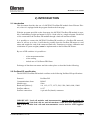
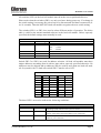
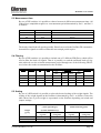
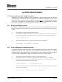
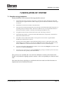
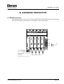
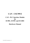
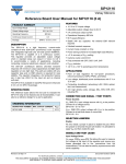
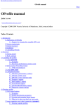
Kokkedal Industripark 4
DK-2980 Kokkedal
Denmark
[email protected]
Tel
+45 49 180 100
Fax
+45 49 180 200
MCE2035 PROFIBUS DP MODULE
Transfer the status and weight of digital loadcells
Applies for:
Program no.:
CONCTR_4.091117.0
Document no.:
1117mu2035-2010-0a.DOC
Date:
2011-05-17
Rev.:
0a
MCE2035: User manual
1) CONTENTS
1) CONTENTS.....................................................................................................................................2
2) INTRODUCTION ...........................................................................................................................3
2.1 Introduction.................................................................................................................................3
2.2 Profibus-DP specification ...........................................................................................................3
3) MCE2010 DESCRIPTION..............................................................................................................4
4) MCE9601 DESCRIPTION..............................................................................................................6
5) DATA EXCHANGE .......................................................................................................................8
5.1 Profibus-DP communication using PPO.....................................................................................8
5.2 Data formats................................................................................................................................9
5.2.1 Unsigned integer format (16 bit)......................................................................................9
5.2.2 Signed integer format (32 bit) ..........................................................................................9
5.2.3 IEEE754 floating point format (32 bit) ..........................................................................10
5.3 Measurement time.....................................................................................................................11
5.4 Filtering.....................................................................................................................................11
5.5 Scaling.......................................................................................................................................11
6) DATA PROCESSING ...................................................................................................................12
6.1 Zeroing, calibration and weight calculation..............................................................................12
6.1.1 Zeroing of weighing system...........................................................................................12
6.1.2 Corner calibration of weighing system ..........................................................................12
6.1.3 Calculation of uncalibrated system weight ....................................................................13
6.1.4 System calibration of weighing system..........................................................................13
7) INSTALATION OF SYSTEM ......................................................................................................14
7.1 Checklist during installation .....................................................................................................14
8) HARDWARE DESCRIPTION .....................................................................................................15
8.1 MCE2035 overview ..................................................................................................................15
8.2 Connection of power and load cells..........................................................................................16
8.3 DIP-switch settings ...................................................................................................................17
8.4 Light Emitting Diodes...............................................................................................................17
8.5 Jumpers .....................................................................................................................................18
8.6 Profibus-DP connector..............................................................................................................19
8.7 Hardware Selftest......................................................................................................................19
8.8 Update times .............................................................................................................................19
9) STATUS CODES ..........................................................................................................................20
Version: 2011-05-17, rev.: 0a
Page: 2
MCE2035: User manual
2) INTRODUCTION
2.1 Introduction
This document describes the use of a MCE2035 Profibus-DP module from Eilersen Electric, when it is equipped with the program listed on the front page.
With the program specified on the front page, the MCE2035 Profibus-DP module is capable of transmitting weight and status for up to 4 load cells in a single telegram. Each load
cell is connected to the Profibus-DP module through a load cell interface module.
It is possible to connect the MCE2035 Profibus-DP module to a Profibus-DP network,
where it will act as a slave. It will then be possible from the Profibus-DP master to read
status and weight for each of the connected load cells. Functions as zeroing, calibration and
calculation of system weight(s) must be implemented on the Profibus-DP master.
By use of DIP-switches it is possible to:
-
select measurement time.
select scaling.
include one of 3 different FIR filters.
Exchange of data between master and slave takes place as described in the following.
2.2 Profibus-DP specification
The MCE2035 Profibus-DP module confirms to the following Profibus-DP specifications:
Protocol:
Communications form:
Module type:
Baud rates [kbit/sec]:
Profibus address:
Profibus connection:
Profibus-DP
RS485
Slave
9.6, 19.2, 93.75, 187.5, 500, 1500, 3000, 6000, 12000
0-127
9-pin sub-D (female) connector
IMPORTANT: Load cell modules and instrumentation must be placed outside the
hazardous zone if the load cells are used in hazardous ATEX (Ex) area. Furthermore,
only ATEX certified load cells and instrumentation can be used in ATEX applications.
Version: 2011-05-17, rev.: 0a
Page: 3
MCE2035: User manual
3) MCE2010 DESCRIPTION
Below the layout of the MCE2010 load cell module is shown. Before using the system the
load cells must be connected to the load cell modules.
Please notice that the load cell and the load cell module MUST be marked
with the same year/serial number. These are printed on the type-plate of the
load cell and on a small sticker placed below the BNC plug on the load cell
module. Load cells and load cell modules MUST NOT be intermixed because
the program in each load cell module is SPECIALLY adapted to one load
cell only (and only this load cell). The load cell module MUST be connected
to exactly the load cell it is intended for and vice versa.
Flat cable connector
10 contacts
TXBB
1
ON
SW
1
8
D1
SYNC
ERR
MCE2010
Eilersen Electric
BNC connector
for loadcell
The load cell modules are connected to each other using the supplied cable (10 pole ribbon
cable). The MCE9601 terminal module (the one with connection terminals) and the
MCE2035 Profibus-DP module are connected using the same cable.
Version: 2011-05-17, rev.: 0a
Page: 4
MCE2035: User manual
All switches (SW1) in the load cell module must be at the correct position before use.
Please notice that the switches (SW1) are only read once during power-up. If a change in
the switch setting is necessary the power has to be disconnected and then reconnected (after 10 seconds). Then the MCE2010 load cell module recognizes the new switch setting.
The switches SW1.1 to SW1.4 are used to select different modes of operation. The below
table is valid for the normal standard software in the load cell module. Unless expressly
specified, the default settings must normally be used.
MCE2010 SW1.1 to SW1.4
SW1 No
Default setting
Function
1
OFF
2
3
4
ON
ON
OFF
Baud rate
OFF:
115200
ON:
230400
Filter, MSB
Filter, LSB
Not used
Switch SW1.5 to SW1.8 are used for address selection. All load cell modules must have
unique addresses ascending from 0 with no gaps unless expressly specified otherwise. No
addresses may be skipped and no addresses may be used by more than one load cell module. In systems with 1-8 load cells switch SW1.5 must be set to OFF.
MCE2010 SW1.6 to SW1.8
SW1.5
SW1.6
SW 1.7
SW1.8
Address
OFF
OFF
OFF
OFF
OFF
OFF
OFF
OFF
OFF
OFF
OFF
OFF
ON
ON
ON
ON
OFF
OFF
ON
ON
OFF
OFF
ON
ON
OFF
ON
OFF
ON
OFF
ON
OFF
ON
0
1
2
3
4
5
6
7
The three LED’s are used to indicate the following conditions:
MCE2010 LED’S
TXBB
Green
D1
Yellow
SYNC ERR
Red
Version: 2011-05-17, rev.: 0a
Lit whenever the load cell module transmits data. Must be
on/flashing rapidly whenever the system is started.
No synchronisation between load cell modules: One or more load
cells not connected to load cell module or poor connection.
No load cell synchronisation: No load cell connected to load cell
module or poor connection.
Page: 5
MCE2035: User manual
4) MCE9601 DESCRIPTION
J2
Below the layout of the MCE9601 terminal module is shown. The MCE9601 module is
used for connection between the Eilersen Electric digital load cell bus at one side and
power supply/equipment at the other side.
J1
D3
D2
D1
JU1
Gnd
B
A
Gnd
+24Vdc
Gnd
I/O
The J1 terminal block is used for connection of the following:
• Terminals Gnd and B (-) and A (+) gives access to the RS485 bus of all equipment
connected to the load cell bus.
• Terminals Gnd and +24Vdc provides external power to the equipment connected to the
load cell bus. These terminals have to be connected to an external +24VDC power supply.
• Terminals Gnd and I/O are the internal synchronization signal used by the load cell
modules. Normally these terminals have no external connection and must be left open.
The J2 connector is used for connecting equipment (load cell modules, communication
modules etc.) on the digital load cell bus by using the supplied ribbon cable with mounted
connectors.
The JU1 jumper is used for hardware synchronisation. Normally this jumper should be left
in the default factory setting which is ON.
The light emitting diodes on the MCE9601 module have the following function:
LED
Function
D1
(Green)
RS485 Communication. This LED should be ON during normal operation (Actually it is
flashing quickly, but this can look like a steady light).
D2
(Yellow)
This LED should be OFF during normal operation. If this lamp is lit, the I/O pin is at reversed polarity.
D3
(Red)
Hardware Synchronisation. This LED should be ON during normal operation (Actually
it is flashing quickly, but this can look like a steady light).
Version: 2011-05-17, rev.: 0a
Page: 6
MCE2035: User manual
Version: 2011-05-17, rev.: 0a
Page: 7
MCE2035: User manual
5) DATA EXCHANGE
5.1 Profibus-DP communication using PPO
Profibus-DP communication with the MCE2035 module uses a so called ’parameterprocess data object’ (PPO) consisting of 26 bytes. This telegram (object) is only used when
transferring data from the slave to the master, since no data are transmitted from the master
to the slave. The structure for this telegram is as follows:
Lc
Register
Lc
Lc
Status(0) Signal(0)
0
2
1
3
4
5
6
Lc
Lc
Status(3) Signal(3)
7
20
21
22 23 24 25
The byte order (MSB/LSB first?) for the individual parts of the telegram is determined by
a jumper. Normally this jumper is set from the factory so that MSB comes first. In the following bit 0 will represent the least significant bit in a register.
LcRegister is a word (two bytes) that constitute a bit register for indication of connected
load cells detected during power on. Hence bit 0-3 will be ON, if the corresponding load
cell (address) was detected during power on. LcRegister is always transferred in 16 bit
unsigned integer format.
LcStatus(X) is a word (two bytes) that constitute a register containing the actual status for
load cell X. LcStatus(X) is always transferred in 16 bit unsigned integer format. During
normal operation this register will be 0, but if an error occurs some bits in the register will
be set resulting in an error code. The meaning of each individual bit in the status register
can be found in the chapter STATUS CODES.
LcSignal(X) is a double word (four bytes) constituting a register containing the actual
weight signal from load cell X. Depending on a jumper LcSignal(X) will be in either 32
bit signed integer format or in IEEE754 floating point format. This jumper is default set
so transfer of LcSignal(X) is done in 32 bit signed integer format. Note that the value is
only valid if the corresponding LcStatus(X) register is 0 indicating no error present. The
scaling of the load cell signal is determined by a DIP-switch as described later.
Since only status and weight for the load cells are transmitted in the telegram, functions
such as status handling, calculation of system weight(s), zeroing and calibration must be
implemented on the Profibus-DP master. Please refer to the chapter DATA PROCESSING
for an explanation on how this typically can be done.
Version: 2011-05-17, rev.: 0a
Page: 8
MCE2035: User manual
5.2 Data formats
The Profibus-DP communication can transfer data in the following three data formats. If
necessary please refer to other literature for further information on these formats.
5.2.1 Unsigned integer format (16 bit)
The following are examples of decimal numbers represented on 16 bit unsigned integer
format:
Decimal
0
1
2
200
2000
20000
Hexadecimal
0x0000
0x0001
0x0002
0x00C8
0x07D0
0x4E20
Binary (MSB first)
00000000
00000000
00000000
00000000
00000111
01001110
00000000
00000001
00000010
11001000
11010000
00100000
5.2.2 Signed integer format (32 bit)
The following are examples of decimal numbers represented on 32 bit signed integer format:
Decimal
Hexadecimal
-20000000
-2000000
-200000
-20000
-2000
-200
-2
-1
0
1
2
200
2000
20000
200000
2000000
20000000
0xFECED300
0xFFE17B80
0xFFFCF2C0
0xFFFFB1E0
0xFFFFF830
0xFFFFFF38
0xFFFFFFFE
0xFFFFFFFF
0x00000000
0x00000001
0x00000002
0x000000C8
0x000007D0
0x00004E20
0x00030D40
0x001E8480
0x01312D00
Version: 2011-05-17, rev.: 0a
Binary (MSB first)
11111110
11111111
11111111
11111111
11111111
11111111
11111111
11111111
00000000
00000000
00000000
00000000
00000000
00000000
00000000
00000000
00000001
11001110
11100001
11111100
11111111
11111111
11111111
11111111
11111111
00000000
00000000
00000000
00000000
00000000
00000000
00000011
00011110
00110001
11010011
01111011
11110010
10110001
11111000
11111111
11111111
11111111
00000000
00000000
00000000
00000000
00000111
01001110
00001101
10000100
00101101
00000000
10000000
11000000
11100000
00110000
00111000
11111110
11111111
00000000
00000001
00000010
11001000
11010000
00100000
01000000
10000000
00000000
Page: 9
MCE2035: User manual
5.2.3 IEEE754 floating point format (32 bit)
Representation of data on IEEE754 floating point format is done as follows:
Byte1
Byte2
Byte3
Byte4
bit7 bit6
bit0 bit7 bit6
bit0 bit7
bit0 bit7
bit0
7
1
0
-1
-7
-8
-15
-16
S
2 …..…. 2
2
2 ……... 2 2 ………….... 2
2 ………..…. 2-23
Sign
Exponent
Mantissa
Mantissa
Mantissa
Formula:
Value = (-1)S * 2(exponent-127) * (I+Mantissa)
Example:
Byte1
0100 0000
Byte2
1111 0000
Byte3
0000 0000
Byte4
0000 0000
Value = (-1)0 * 2(129-127) * (1 + 2-1 + 2-2 + 2-3) = 7.5
Please note that if transfer of MSB first has been selected (default setting), the byte with
the “sign” will come first in the weight indications, and if LSB first has been selected the
byte with the “sign” will come last in the weight indications.
Version: 2011-05-17, rev.: 0a
Page: 10
MCE2035: User manual
5.3 Measurement time
By use of DIP-switches it is possible to choose between 4 different measurement times. All
load cells are sampled/averaged over a measurement period determined by Sw1.1 and Sw1.2
as follows:
SW1.1
SW1.2
Measurement time
OFF
OFF
ON
ON
OFF
ON
OFF
ON
20 ms
100 ms
400 ms
2000 ms
NOTE: Upon default delivery SW1.1 is OFF and SW1.2 is ON, so that 100ms measuring time is achieved.
The hereby found load cell signals (possibly filtered) are used in the Profibus-DP communication until new signals are achieved when the next sample period expires.
5.4 Filtering
By use of DIP-switches it is possible to include one of 3 different FIR filters, which will be
used to filter the load cell signals. Thus it is possible, to send the unfiltered load cell signals achieved over the selected measurement period through one of the following FIR filters, before the results are transmitted on the Profibus:
SW1.4
SW1.3
No.
Taps
OFF
ON
OFF
ON
OFF
OFF
ON
ON
0
1
2
3
9
21
85
Damping
Frequency
Tavg
20ms
Tavg
100ms
Tavg
400ms
Tavg
2000ms
-
-
-
-
12.0 Hz
2.4 Hz
0.6 Hz
0.12 Hz
6.0 Hz
1.2 Hz
0.3 Hz
0.06 Hz
1.5 Hz
0.3 Hz
0.075Hz
0.015Hz
-80dB
-80dB
-80dB
NOTE: With both switches OFF, which is default setting upon delivery, no filtering is performed.
5.5 Scaling
By use of a DIP-switch it is possible to select the desired scaling of the weight signals. The
scaling of the weight signals on the Profibus is determined by Sw2.1 as follows, where the
table shows how a given weight is represented on the Profibus depending on switch and
jumper settings:
Weight
[gram]
1,0
123,4
Version: 2011-05-17, rev.: 0a
JU7 = OFF
(32 bit signed integer)
(normal default delivery)
Sw2.1 = OFF
Sw2.1 = ON
(1 gram)
(1/10 gram)
1
123
10
1234
JU7 = ON
(IEEE754 floating point)
Sw2.1 = OFF
(1 gram)
Sw2.1 = ON
(1/10 gram)
1,000
123,000
10,000
1234,000
Page: 11
MCE2035: User manual
6) DATA PROCESSING
6.1 Zeroing, calibration and weight calculation
Calculation of system weight(s) is done by addition of the weight registers for the load
cells belonging to the system. This is explained below. Note that the result is only valid if
all status registers for the load cells in question indicate no errors. It should also be noted
that it is up to the master to ensure the usage of consistent load cell data when calculating
the system weight (the used data should come from the same telegram).
6.1.1 Zeroing of weighing system
Zeroing of a weighing system (all load cells in the specific system) should be performed as
follows, taking into account that no load cell errors may be present during the zeroing procedure:
1)
2)
The weighing arrangement should be empty and clean.
The Profibus-DP master verifies that no load cell errors are present, after which it reads and stores
the actual weight signals for the load cells of the actual system in corresponding zeroing registers.
LcZero[x]=LcSignal[x]
3)
After this the uncalibrated gross weight for load cell X can be calculated as:
LcGross[X] = LcSignal[X] – LcZero[X]
6.1.2 Corner calibration of weighing system
In systems where the load is not always placed symmetrically the same place (for example
a platform weight where the load can be placed randomly on the platform when a weighing
is to take place), a fine calibration of a systems corners can be made, so that the weight indicates the same independent of the position of the load. This is done as follows:
1)
2)
3)
Check that the weighing arrangement is empty. Zero the weighing system.
Place a known load (CalLoad) directly above the load cell that is to be corner calibrated.
Calculate the corner calibration factor that should be multiplied on the uncalibrated gross weight of
the load cell in order to achieve correct showing as:
CornerCalFactor[x] = (CalLoad)/(LcGross[x])
After this the determined corner calibration factor is used to calculate the calibrated gross weight
of the load cell as follows:
LcGrossCal[x] = CornerCalFactor[x] * LcGross[x]
Version: 2011-05-17, rev.: 0a
Page: 12
MCE2035: User manual
6.1.3 Calculation of uncalibrated system weight
Based on the load cell gross values (LcGross[x] or LcGrossCal[x]), whether they are
corner calibrated or not, a uncalibrated system weight can be calculated as either:
Gross = LcGross[X1] + LcGross[X2] + …
or:
Gross = LcGrossCal[X1] + LcGrossCal[X2] + …
6.1.4 System calibration of weighing system
Based on the uncalibrated system weight a system calibration can be made as follows:
1)
2)
3)
Check that the weighing arrangement is empty. Zero the weighing system.
Place a known load (CalLoad) on the weighing arrangement. NOTE: In order to
achieve a correct calibration of the system it is recommended, that the used calibration load is at least 50% of the system capacity.
Calculate the calibration factor that should be multiplied on the uncalibrated system weight in order to achieve correct showing as:
CalFactor = (CalLoad)/(Actual Gross)
After this the determined calibration factor is used to calculate the calibrated system weight as follows:
GrossCal = CalFactor * Gross
If the determined calibration factor falls outside the interval 0.9 to 1.1 it is very
likely that there is something wrong with the mechanical part of the system. This
does not however apply to systems, which do not have a load cell under each supporting point. For example on a three legged tank with only one load cell, you
should get a calibration factor of approximately 3 because of the two “dummy”
legs.
Version: 2011-05-17, rev.: 0a
Page: 13
MCE2035: User manual
7) INSTALATION OF SYSTEM
7.1 Checklist during installation
During installation of the system the following should be checked:
1)
The Profibus-DP master should be configured to communicate with the MCE2035 Profibus-DP
module using the supplied GSD file. When configuring with the GSD file a MCE2035 station type
is selected.
2)
All hardware connections are made as described below.
3)
The load cells are mounted mechanically and connected to the Profibus-DP module using their corresponding load cell interface module. The load cell addresses are set using the DIP-switches on
the load cell interface modules, so that they forth running from address 0 (0-3).
4)
Using DIP-switches the desired measurement time, filter and scaling is selected.
5)
The Profibus-DP module is connected to the Profibus-DP network, and possibly a termination is
made at this Profibus-DP slave.
6)
The address of the Profibus-DP module is set using Sw2.2-Sw2.8. Power is applied and the
Profibus-DP communication is started.
7)
Verify that the red LED (PBE) on the Profibus-DP module is NOT lit, and that the yellow LEDs
(DES and RTS) are lit/flashing. Verify that the TXBB LED on the Profibus-DP module is lit and
that the TXBB LED’s on the load cell interface modules are also lit (can flash slightly).
8)
Verify that the Profibus-DP module has found the correct load cells (LcRegister), and that no load
cell errors are indicated (LcStatus(x)).
9)
Verify that every load cell gives a signal (LcSignal(x)) by placing a load directly above each load
cell one after the other (possibly with a known load).
The system is now installed and a zero and fine calibration is made as described earlier.
Finally verify that the weighing system(s) returns a value corresponding to a known actual
load.
Note that in the above checklist no consideration has been made on which functions are
implemented on the Profibus DP master.
Version: 2011-05-17, rev.: 0a
Page: 14
MCE2035: User manual
8) HARDWARE DESCRIPTION
8.1 MCE2035 overview
The following figure is an overview of how a MCE2035 Profibus-DP system is made using
four MCE2010 load cell modules and a MCE9601 connection module:
Ribbon cable for loadcell bus
TXBB
SW
1
TXBB
TXBB
TXBB
TXBB
SW
1
SW
1
SW
1
SW
1
GND
SW
2
D1
D2
PBE
DES
RTS
MCE2035
B
A
D1
SYNC
ERR
D1
SYNC
ERR
D1
SYNC
ERR
D1
SYNC
ERR
GND
+24V
+ 24 VDC
GND
0 VDC
I/O
MCE2010
MCE2010
MCE2010
MCE2010
MCE9601
9 pole SUB-D connector
for Profibus
1.
2.
3.
4.
5.
6.
7.
8.
9.
RS485-A(postive line) / (Siemens : B-line)
RTS, Request to send
0 Vdc, Gnd
+5VDC (Vout)
BNC connectors for load cells
RS485-B(negative line) / (Siemens : A-line)
Version: 2011-05-17, rev.: 0a
Page: 15
MCE2035: User manual
8.2 Connection of power and load cells
This chapter describes the connection of power supply and load cells to the MCE2035
module.
IMPORTANT: The used power supply must be stable and free of transients. It may therefore be necessary to use a separate power supply dedicated to the weighing system, and not
connected to any other equipment.
The 10 pole connector (J2) on the MCE2035 module is connected to the 10 pole connectors on the load cell interface modules (MCE2010) and to the 10 pole connector on the
MCE9601 connection module using the supplied ribbon cable with mounted connectors.
Through this bus cable connection of power supply to the individual modules is achieved
and data can be transferred from the load cell modules to the MCE2035 module.
The MCE9601 module has the following connections in the blue connector (J1):
MCE9601 CONNECTOR
CONNECTION
GND
B (DATA- )
A (DATA+)
GND
+24V
GND
I/O
+24VDC (Vin)
0 VDC (GNDin)
-
The 10 pole connector (J2) on the MCE2035 Profibus-DP module has these connections:
MCE2035 J2 CONNECTER
FUNCTION
J2.1 - J2.2
J2.3 - J2.4
J2.5 - J2.6
J2.7 - J2.8
J2.9 - J2.10
RS485-B (DATA- )
RS485-A (DATA+)
0 VDC (GNDin)
+24VDC (Vin)
I/O line
Version: 2011-05-17, rev.: 0a
Page: 16
MCE2035: User manual
8.3 DIP-switch settings
The Profibus-DP module is equipped with a 4 pole DIP-switch block that has the following
function:
SWITCH
Sw1.1-Sw1.2
FUNCTION
Measurement time
Used to select the desired measurement time as described in an earlier chapter. Note
that these switches are only read during power on.
Sw1.3-Sw1.4
Filtering
Used to select the desired filter as described in an earlier chapter. Note that these
switches are only read during power on.
and a 8 pole DIP-switch block that has the following function:
SWITCH
Sw2.1
FUNCTION
Scaling
Used to select the desired scaling as described in an earlier chapter. Note that these
switches are only read during power on.
Sw2.2-Sw2.8
Selection of Profibus-DP communication address
The address is selected as the DIP-switches are binary coded, so Sw2.2 is MSB and
Sw2.8 is LSB. Note that these switches are only read during power on.
8.4 Light Emitting Diodes
The Profibus-DP module is equipped with 6 light emitting diodes (LED). These LED’s
have the following function:
LED
FUNCTION
TXBB
Communication with load cells
(Green)
Profibus-DP module is communicating with load cells.
D1
Reserved for future use
(Green)
D2
Reserved for future use
(Green)
PBE
Profibus Error (when initializing the SPC3)
(Red)
The SPC3 Profibus-DP controller was not initialized correctly.
DES
Data Exchange State
(Yellow)
RTS
(Yellow)
Version: 2011-05-17, rev.: 0a
Exchange of data between Profibus-DP slave and master.
RtS signal (SPC3)
The Profibus-DP module sends to the master.
Page: 17
MCE2035: User manual
8.5 Jumpers
The Profibus-DP module is equipped with 7 jumpers. These jumpers have these functions:
JUMPER
JU1
JU2-JU4
JU6
JU7
JU8
Version: 2011-05-17, rev.: 0a
FUNCTION
Reserved for future use
(normal default factory setting is OFF)
Reserved for future use (termination)
(normal default factory setting is OFF)
Reserved for future use
(normal default factory setting is OFF)
Selection of (32 Bit Signed Integer) / (IEEE754) data format
The jumper determines if the weight indications in the telegram are in
32 bit signed integer or in IEEE754 floating point format.
OFF: 32 bit signed integer format (normal setting from factory)
ON: IEEE754 floating point format
Selection of LSB/MSB data format
The jumper determines the byte order in which data are transmitted/received.
OFF: LSB first
ON: MSB first (normal setting from factory)
Page: 18
MCE2035: User manual
8.6 Profibus-DP connector
The Profibus-DP module is equipped with a nine pole female sub-D connector (J1) for
connection to the Profibus-DP network. The connector is a standard Profibus-DP connector. Termination of the Profibus should take place in the sub-D connector (male) of the cable. The specific terminals in the connector have the following function:
J1 TERMINALS
J1.1
J1.2
J1.3
J1.4
J1.5
J1.6
J1.7
J1.8
J1.9
FUNCTION
Not used
Not used
RS485-A (positive line) (Siemens designation: B line)
Request to Send (RTS)
0 VDC (Gnd)
+5VDC (Vout)
Not used
RS485-B (negative line) (Siemens designation: A line)
Not used
Note that some companies use different designations for the RS485-A and the RS485-B lines. Therefore the
polarity of the lines has been listed.
8.7 Hardware Selftest
During power-on the Profibus-DP module will perform a hardware selftest. The test will
cause the light emitting diodes D1, D2 and PBE to turn on and off shortly, one at a time.
8.8 Update times
Please note that update times across the Profibus-DP communication depends on the specific
Profibus-DP configuration (selected baudrate, number of slaves, scan times etc.).
Version: 2011-05-17, rev.: 0a
Page: 19
MCE2035: User manual
9) STATUS CODES
Status codes are shown as a 4 digit hex number. If more than one error condition is present
the error codes are OR’ed together.
CODE
(Hex)
0001
0002
0004
0008
0010
0020
0040
0080
0100
0200
0400
0800
1000
2000
4000
8000
CAUSE
Invalid/missing ’sample’ ID
Bad connection between communication module and load cell module.
Load cell timeout
Check that the load cell is connected to the load cell module.
Load cell not synchronized
Bad connection between load cell and load cell module.
Hardware synchronization error
Cable between load cell modules shorted or disconnected.
Power failure
Supply voltage to load cells is to low.
Overflow in weight calculation
Internal error in load cell module.
Invalid/missing ’latch’ ID
Bad connection between communication module and load cell module.
No answer from load cell module
No data is received from this load cell module. This can be caused by the
removal of the load cell module, no power to the module or that the connection between load cell module and communication module is broken.
Reserved for future use
Reserved for future use
Reserved for future use
No load cell modules answer
Bad connection between communication module and load cell module. Not
all telegrams from communication module are received in load cell module.
Reserved for future use
Reserved for future use
Reserved for future use
Reserved for future use
Version: 2011-05-17, rev.: 0a
Page: 20