1
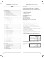
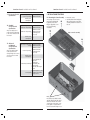
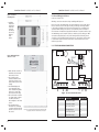
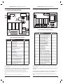
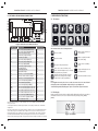
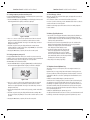
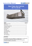
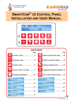
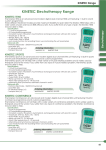
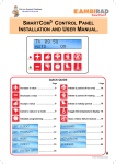
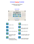
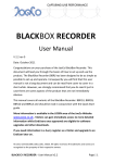
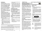
2
SmartCom
Installation and User Manual
for Lite, Standard, Advanced and Network versions
The SmartCom2 control is factory set to operate on warm air systems. To change
settings for radiant products please refer to Section 4, Engineer Functions.
Quick Guide
Increase a value
PLUS
VENT ONLY
Decrease a value
OVERTIME
MINUS
Accept a newly entered value
OK
HOLIDAY
UNDO
Press once to cancel overtime, vent,
exam, off and holiday modes or a
newly entered value not yet OK’d
CHECK TEMP
Initiate a period of forced
vent operation
Initiate or quickly extend a
period of heating
Set the control to holiday
mode
Toggle the display to show
the temperatures
12
9
3
6
SETTINGS
Change the settings (see diagram
below)
Clear a flame failure lockout
LOCKOUT
SET
TEMPERATURES
SET
OFF
12
9
12
3
9
12
6
9
SETTINGS
3
6
3
SETTINGS
6
SETTINGS
Initialise Programming
Press repeatedly to
access required setting
12
SET 9
3
PROGRAM
6
TIMES SETTINGS
12
9
3
6
SET
CLOCK
SETTINGS
SET
12
VENT 9
3
ONLY
6
MODE SETTINGS
UNDO
SET
EXAM
MODE
Press to return
to main display
Optional
12
9
12
3
9
6
SETTINGS
SET
HEAT ONLY
MODE
9
3
6
12
3
6
SETTINGS
SET
FROST ONLY
MODE
SETTINGS
SET
AUTO
MODE
SmartCom2 Control Installation and User Manual
SmartCom2 Control Installation and User Manual
INTRODUCTION
CONTENTS
Introduction........................................................................................................................... 3
1
2
3
4
2
Technical Specifications ................................................................................................
1.1
Operating Environment ...................................................................................
1.2
Performance Specifications .............................................................................
1.3
Lite Version Electrical Specifications ...............................................................
1.4
Standard Version Electrical Specifications .....................................................
1.5
Advanced and Network Version Electrical Specifications ............................
3
3
3
4
4
4
Installation Instructions ............................................................................................... 5
2.1
Mounting the Control Assembly ..................................................................... 5
2.2
General Wiring Specifications ......................................................................... 7
2.3
Lite Version Wiring Connections ..................................................................... 7
2.4
Standard Version Wiring Connections ........................................................... 8
2.5
Advanced Version Wiring Connections .......................................................... 9
2.6
Network Version Wiring Connections .......................................................... 10
Operating Instructions ...............................................................................................
3.1
The buttons .....................................................................................................
3.2
The display .......................................................................................................
3.3
Setting the clock .............................................................................................
3.4
Setting the operating modes ........................................................................
3.5
Setting the program (on/off times) ..............................................................
3.6
Setting the day and night temperatures .....................................................
3.7
Optional Password (PIN protection) .............................................................
3.8
Networked Controllers (SC-NET only) ..........................................................
3.8.1 Setting up the network ..................................................................................
3.8.2 Operating the master controller ...................................................................
3.9
Checking the temperature .............................................................................
3.10
Setting a temporary Holiday period .............................................................
3.11
Setting a temporary overtime extension period ........................................
3.12
Setting a temporary vent period ..................................................................
3.13
Error message:- Lockout ................................................................................
3.14
Battery Type & Replacement ........................................................................
3.15
Optimum Start and Optimum Stop ..............................................................
11
11
11
12
12
13
15
15
16
16
17
17
17
18
18
19
19
19
Engineer Functions ......................................................................................................
4.1
General Password (PIN Protection) ...............................................................
4.2
Programming The Engineer Functions .........................................................
4.3
The Engineer Variables ...................................................................................
4.4
External Inputs ................................................................................................
4.5
Default Priority Settings .................................................................................
20
20
21
21
23
23
This manual describes the Installation and Operation of the ‘SmartCom2’ control
unit. NB This control must be installed according to the current IEE Wiring
Regulations and should include full disconnection means and fusing appropriate to
the connected loads.
1 TECHNICAL SPECIFICATIONS
1.1 Operating Environment
Operating temperature range: 0º C to 40º C
Operating humidity range: 0 to 90% RH.
Control IP rating: IP30
Pollution degree: II environment
Control safety construction: class II
Mains supply: 230Vac nominal, 200Vac to 265Vac actual, 50Hz.
On board supply fuse: 1AT
Rated impulse voltage: 2500V
1.2 Performance Specifications
●
●
●
●
●
●
●
●
An independently mounted electronic control for surface mounting.
Operation is by Class A software and Type 1A action.
The mains supply to the electronic circuit is protected by a time delay fuse.
Flame failure input: 230Vac nominal, 200Vac to 265Vac actual, 50Hz. Presence of
voltage indicates flame failure.
The burner reset relay output is either Live or Neutral which is selected by a plug-in
jumper (Live only in case of Lite version).
Remote volt-free switch outputs will be 24Vdc/5mA
The built-in room temperature sensor has a measuring range of 0º C to 30º C with
a resolution of 0.2º C.
Temperature sensor readings can be offset to allow for errors due to sensor
tolerances and location. NB Frost protection readings are also affected by offsets.
● Built-in and remote
room temperature sensor
Measuring range: 0 – 30º C.
Resolution: 0.2º C.
Untrimmed accuracy over range: +/- 1.4º C.
Accuracy over range with offset: +/- 0.6º C.
(See section 4.3)
● Unless well ventilated, heat generated in the control may cause the built-in
sensor to over-read temperatures.
● Remote duct temperature
sensor
Measuring range: 10° – 60º C.
Resolution: 0.2º C.
Accuracy over range: +/- 3.0º C.
3
SmartCom2 Control Installation and User Manual
1.3 Lite Version Electrical
Specifications
Burner reset, Heat and 7A/240Vac resistive
Vent 1 relay rating: 2A/240Vac inductive
Control power
3W
consumption:
1.4 Standard
Version Electrical
Specifications
The power supply is nonisolated, therefore all wiring
to the control must be mains
level rated.
Burner reset, Heat and 7A/240Vac resistive
Std Vent 1 relay rating: 2A/240Vac inductive
550W Vent 1 relay rating:
SmartCom2 Control Installation and User Manual
2 INSTALLATION INSTRUCTIONS
2.1 Mounting the Control Assembly
The housing consists of a two
part plastic moulding held
together by four screws.
Plugs are supplied to cover
the screws following
installation.
10A/240Vac resistive
3A/240Vac inductive,
(550W single phase
motor, max)
● Remove the screws.
● Carefully lift the lid and unplug the
ribbon cable from the power PCB
assembly situated in the bottom of
the case.
Figure - Controller assembly
Control power
3W
consumption:
1.5 Advanced
and Network
Version Electrical
Specifications
The power supply is SELV
isolated, therefore low
voltage wiring to the control
does not need to be mains
level rated.
All relays except Vent 1 10A/240Vac resistive
rating: 2A/240Vac inductive
10A/240Vac resistive
3A/240Vac inductive,
Vent 1 relay rating:
(550W single phase
motor, max)
Control power
5W
consumption:
Screened twisted pair
Daisy-chain
configuration.
Communications wiring: Belden 9841 cable
recommended.
Maximum cable length
= 500m
Output impedance = 500
0 – 10V signals Ohm. Max current drive
capacity = 5mA
Note :
Knockouts are provided for cable
glands to allow mains and control
cables to be fitted to the control
assembly. Knock the plastic out to
fit the glands as required. Never
leave holes that allow finger access.
4
5
SmartCom2 Control Installation and User Manual
SmartCom2 Control Installation and User Manual
Figure - Controller
mounting holes
2.2 General Wiring Specifications
● A drilling
template is
provided to
enable the
controller
assembly to
be securely
fixed to a
solid
surface.
All wiring connections must be made by a suitably qualified person.
Connect as shown below.
Please refer to the following wiring connection drawings (2.3 to 2.6) and observe
the note at the bottom of each page referring to cable type and length. Failure
to follow these guidelines may result in electrical interference or unsatisfactory
operation. When making connections to screw terminals please ensure that no
more than 6mm of insulation is stripped back and that no stray wire strands escape.
The Ambi-Rad group of companies produces a wide range of product types. With
each product despatched, there are specific wiring instructions showing how to
connect the controls detailed in these instructions, to the product. It is important
to read both the product instructions and these control instructions to ensure
satisfactory operation.
Figure - Minimum height
above floor level.
!
● Ensure that the controller is
installed no less than 1.5m
above the floor level.
● The controller can be
positioned with the cable
entry to the bottom or the
top depending on the cable
routing.
● The lid with display and
connecting ribbon cable
can be rotated through 180
degrees to accommodate
top or bottom cable entry.
● Do not mount the controller
on a warm surface or where
it could be affected by
direct sunlight or other heat
sources.
● The mounting surface
should be non-conducting
or earth bonded and should
prevent access to the rear of
the control.
6
NEUT
FUSE
2.3 LITE VERSION WIRING CONNECTIONS
LIVE
!
!
!
!
9
6
40
1
2 10
Figure - Lite version PCB connections
Note: The recommended minimum mounting height
only applies when the internal sensor is used.
Terminal No:
Connection
Capacity mm2
9
Burner Reset output
2.5
6
Heat 1 relay output
2.5
40
Vent 1 relay output
2.5
1
Live supply input
2.5
2
Neutral supply input
2.5
10
Flame failure input
2.5
7
SmartCom2 Control Installation and User Manual
SmartCom2 Control Installation and User Manual
2.5 ADVANCED VERSION WIRING CONNECTIONS
2.4 STANDARD VERSION WIRING CONNECTIONS
!
NEUT
LIVE
B2
B0
B1
FUSE
S/R0
S/R1
66
64
20
B2
B0
B1
D1
D0
S/R1
S/R0
!
FUSE
LIVE
!
!
41 40
!
!
9
5 6 40 41
1 2 10
Figure - Standard version PCB connections
Terminal No:
Connection
Capacity mm2
9
Burner Reset output
2.5
5
Time relay output
2.5
6
Heat 1 relay output
2.5
40
Vent 1 relay output
2.5
41
Vent 1 relay input (550W relay
version only)
2.5
1
Live supply input
2.5
2
Neutral supply input
2.5
10
Flame failure input
2.5
S/R0
Remote room temperature sensor ‘A’
1.5
S/R1
Remote room temperature sensor ‘B’
1.5
B1
Remote On input (BMS ON INPUT)
1.5
B0
Remote common (Output to BMS)
1.5
B2
Remote input (see 4.4)
1.5
7
8
!
9
25
NEUT
14
5
!
6
!
1/L 2/N 10
Figure - Advanced version PCB connections
Terminal No:
41
40
7
8
9
25
14
5
6
1
2
10
66
64
20
S/R0
S/R1
D0
D1
B1
B0
B2
Connection
Vent 1 relay input (550W/low fan)
Vent 1 relay output (550W/low fan)
Heat 2 relay input (2 stage)
Heat 2 relay output (2 stage)
Burner Reset output
Vent 3 relay output (damper)
Vent 2 relay output (high fan)
Time relay output (CRFR)
Heat 1 relay output (1 stage)
Live supply input
Neutral supply input
Flame failure input
Channel 1, 0~10V output (GM44)
Channel 1 and 2 common output
Channel 2, 0~10V output (damper)
Remote room temperature sensor ‘A’
Remote room temperature sensor ‘B’
Remote duct temperature sensor ‘A’
Remote duct temperature sensor ‘B’
Remote On input (BMS ON input)
Remote common (output to BMS)
Remote input (see 4.4)
Capacity mm2
2.5
2.5
2.5
2.5
2.5
2.5
2.5
2.5
2.5
2.5
2.5
2.5
1.5
1.5
1.5
1.5
1.5
1.5
1.5
1.5
1.5
1.5
A terminal block is supplied to enable multiple connections to BO/B2 as detailed in product
wiring connections.
A terminal block is supplied to enable multiple connections to BO/B2 as detailed in product
wiring connections.
Remote switch inputs should be connected by 6A mains* cable of maximum length 100m. The
remote temperature sensor may be placed at a distance of up to 100m (maximum) from the
control unit, using screened 6A mains* cable. Connect the screen to terminal B0.
0-10V outputs and remote switch inputs should be connected by 0.75mm2 cable of maximum
length 100m.
All sensor and signal wiring should be kept separate from mains wiring to minimise noise
pick-up.
*The power supply is non-isolated, therefore all wiring to the control must be mains rated.
8
The remote temperature sensor may be placed at a distance of up to 100m (maximum) from
the control unit, using screened 0.75mm2 cable. Connect the screen to terminal B0.
All sensor and signal wiring should be kept separate from mains wiring to minimise noise
pick-up.
9
SmartCom2 Control Installation and User Manual
SmartCom2 Control Installation and User Manual
3 OPERATING INSTRUCTIONS
2.6 NETWORK VERSION WIRING CONNECTIONS
3.1 The Buttons
66
64
20
C1
C0
C2
B2
B0
B1
D1
D0
S/R1
S/R0
PLUS
OK
VENT ONLY
OVERTIME
LOCKOUT
HOLIDAY
CHECK TEMP
FUSE
LIVE
!
!
41 40
7
8
!
9
25
NEUT
14
5
12
!
6
!
9
1/L 2/N 10
MINUS
Figure - Network version PCB connections
Terminal No:
41
40
7
8
9
25
14
5
6
1
2
10
66
64
20
C1
C0
C2
S/R0
S/R1
D0
D1
B1
B0
B2
Connection
Vent 1 relay input (550W/low fan)
Vent 1 relay output (550W/low fan)
Heat 2 relay input (2 stage)
Heat 2 relay output (2 stage)
Burner Reset output
Vent 3 relay output (damper)
Vent 2 relay output (high fan)
Time relay output (CRFR)
Heat 1 relay output (1 stage)
Live supply input
Neutral supply input
Flame failure input
Channel 1, 0~10V output (GM44)
Channel 1 and 2 common output
Channel 2, 0~10V output (damper)
Comms ‘A’ input/output (M&S)
Comms GND output (M&S)
Comms ‘B’ input/output (M&S)
Remote room temperature sensor ‘A’
Remote room temperature sensor ‘B’
Remote duct temperature sensor ‘A’
Remote duct temperature sensor ‘B’
Remote On input (BMS ON input)
Remote common (output to BMS)
Remote input (see 4.4)
Capacity mm2
2.5
2.5
2.5
2.5
2.5
2.5
2.5
2.5
2.5
2.5
2.5
2.5
1.5
1.5
1.5
1.5
1.5
1.5
1.5
1.5
1.5
1.5
1.5
1.5
1.5
3
6
UNDO
SETTINGS
The ten buttons have the following functions:
VENT ONLY
Initiate a period of forced
vent operation
OVERTIME
Initiate or quickly extend a
period of heating
Increase a value
PLUS
Decrease a value
MINUS
Accept a newly entered value
OK
HOLIDAY
UNDO
12
9
3
6
SETTINGS
Press once to cancel overtime, vent,
exam, off and holiday modes or a newly
entered value not yet OK’d
Initialise and step through: off mode,
exam mode*, setting clock, heating
control modes, and programming
CHECK TEMP
Set the control to holiday
mode
Toggle the display to show
the temperatures
Clear a flame failure lockout
LOCKOUT
Note:
If no keypad action takes place for 60 seconds, the current selection is cancelled and
the display returns to day and time and previously set operating mode.
* Exam Heating mode (EH) will appear only if selected in the engineer functions.
3.2 The Display
During normal operation the time and day will be displayed as well as the operating
mode that has been set. The screen below shows the operating mode; [FROST]
[ONLY].
A terminal block is supplied to enable multiple connections to BO/B2 as detailed in product
wiring connections.
0-10V outputs and remote switch inputs should be connected by 0.75mm2 cable of maximum
length 100m.
The remote temperature sensor may be placed at a distance of up to 100m (maximum) from the
control unit, using screened 0.75mm2 cable to improve noise rejection. Connect the screen to
terminal B0. Master-slave communication is by screened twisted pair cable, RS 485 compatible,
such as Belden 9841. Maximum overall system length is 500m. Connect screens to B0 and C0.
Figure - Frost Mode
All sensor and signal wiring should be kept separate from mains wiring to minimise noise pick-up.
10
11
SmartCom2 Control Installation and User Manual
SmartCom2 Control Installation and User Manual
3.3 Setting the Clock
9
OK?
Auto mode: Heating and ventilation
operate automatically depending on the
room temperature, time/set temperature
program and the control method
selected. Ventilation is disabled during
off periods of the time program.
OK?
Frost Only mode: Heating operates
automatically depending on the room
temperature and control method
selected. The set temperature is fixed at
5°C. Ventilation is disabled.
OK?
Heat Only mode: Heating operates
automatically depending on the room
temperature, time/set temperature
program and the control method
selected. Ventilation is disabled.
OK?
Vent Only mode: Ventilation operates
automatically depending on the room
temperature, time/set temperature
program and the control method selected.
Heating is disabled. Ventilation is disabled
during off periods of the time program.
SET
Press the SETTINGS button up to
3 times until the set clock display
SETTINGS
appears. The icons [SET], [CLOCK]
and [OK?] will be displayed with the
[CLOCK] icon flashing. (Enter your PIN
code if prompted.)
12
3
SET
CLOCK
6
AUTO
OK?
Figure – Set the Clock
Press the OK button to accept the set clock function.
One of the day icons will now flash.
Press + or – until the correct day is displayed and press OK to accept.
Next the Hours display will flash.
Press + or – until the correct hours are displayed and press OK to accept.
Next the Minutes display will flash.
Press + or – until the correct minutes are displayed.
SET
FROST
ONLY
SET
HEAT
Press the OK button to accept.
OK
ONLY
The controller will return to normal
operation.
SET
3.4 Setting the Operating Modes
Pressing the settings button will present the options in the following sequence:
1 Set Off mode
2 Set Exam heating mode*
3 Set Clock
4 Set Auto mode
5 Set Frost Only mode
6 Set Heat Only mode
7 Set Vent Only mode
8 Set Program
9 Set Temperatures
* Exam Heating mode (EH) will appear only if selected in the engineer functions.
12
9
3
6
SETTINGS
Press SETTINGS until the required
mode is displayed and flashing.
SET
OK?
SET
2
OK?
TEMPDAY
SET
(Enter your PIN code if prompted.)
Off mode: All the heating functions
switch off. Please note this is an OFF
function and service engineers must
always isolate the mains supply and not
use the off mode instead of a mains
isolation switch.
*Exam Heating mode: If the control is used
on a system installed in a sports hall, a
temporary increase in temperature can be
set to improve comfort for people sitting in
the building. Heating will be controlled to
“temperature 2” as detailed in Section 3.6.
Exam Heating mode can only be set during
an ON period and will last only until the
next OFF period.
CLOCK
VENT ONLY
OK?
Set Clock: See section 3.3 above.
OK
Press the OK button to accept
the chosen mode.
The controller will adopt, and continue
in, that mode of operation.
3.5 Setting the program (on/off times)
Please note the following on/off times and temperature settings in the table shown
below have been factory set. If these on/off times and temperature settings are
acceptable to you then choose the “AUTO” mode (see section 3.4) and the products
connected to the control will operate in accordance with the detail in the table.
If the settings are not acceptable then continue to read this section to change as
required.
Factory Settings
Monday
ON 1 = 08:00
OFF 1 = 16:30
ON 2 = --:--
ON 3 = Unused
Tuesday
ON 1 = 08:00
OFF 1 = 16:30
ON 2 = --:--
ON 3 = Unused
Wednesday
ON 1 = 08:00
OFF 1 = 16:30
ON 2 = --:--
ON 3 = Unused
Thursday
ON 1 = 08:00
OFF 1 = 16:30
ON 2 = --:--
ON 3 = Unused
Friday
ON 1 = 08:00
OFF 1 = 16:30
ON 2 = --:--
ON 3 = Unused
Saturday
ON 1 = --:--
OFF 1 = Unused ON 2 = Unused ON 3 = Unused
Sunday
ON 1 = --:--
OFF 1 = Unused ON 2 = Unused ON 3 = Unused
ON / Day Temperature = 18.0ºC
OFF / Night Temperature = 5.0ºC
12
13
SmartCom2 Control Installation and User Manual
SmartCom2 Control Installation and User Manual
Press the SETTINGS button
repeatedly until the set program
SETTINGS
display appears. The icons [SET],
[PROGRAM] and [OK?] will be displayed
with the [PROGRAM] icon flashing.
(Enter your PIN code if prompted.)
12
9
3
3.6 Setting the Day & Night Temperatures
SETPROGRAM
6
12
OK?
9
3
6
SETTINGS
Figure - Set Program
OK
OK
Press the OK button to accept the Set Program function.
The day of week icon will flash. (The time area will be blank.)
Press + button if you want to choose another day and press OK to accept.
The timeslot icon [ON 1] will be displayed and the hours and minutes display will flash.
Press + or – until the required ON time is displayed. The time will change in 10 minute
steps. Press OK to accept. Optimum start may affect the ON time. Optimum stop may
affect the off time (see section 3.15).
Figure - Set 1st ON Time
Pressing OK will advance the display as follows:
● An ON time will advance to its corresponding OFF time.
● If an ON time has been set to unused, “--:--“, pressing OK will then allow you to
select a different day.
● To change an unused ON time to “--:--” to a useable ON/OFF slot, press the - button.
Figure - Set Unused Time Slot
● If a day, e.g. Saturday or Sunday, requires no program, then set all the ON
times for that day to unused, “--:--“. (Press the + button until it changes from
“23:50” to “--:--“.)
● An OFF time will advance to the next ON time of the same day, even if the ON time
has been set to unused.
● 3 timeslots per day (each timeslot includes an on and off time) are allowed.
● Advancing to a new day will cause the day icon to flash and the settings for the
new day may be programmed.
● To return to the main display, advance the day of the week until “End” appears
and press OK.
Automatic Copy Feature
When timeslots for Monday are programmed, these timeslots will automatically be
copied to the rest of the (5 day) week. Timeslots for Saturday and Sunday will not
be copied to and must be set separately. If one copied timeslot requires amendment
scroll through to the particular setting and change the times required.
14
Press the SETTINGS button repeatedly until the icons [SET], [TEMP] and
[OK?] are displayed with the [TEMP] icon flashing (enter your PIN code if
prompted).
Press the OK button to accept the Set Temperatures function.
SET
1
TEMPDAY
°C
OK?
Figure – Set the Day Temperature(s)
The [SET], [TEMP], [DAY] and [1] icons will be displayed and the temperature digits
will be flashing.
Press + or – until the desired temperature is displayed, then press OK to accept.
*Next the [SET], [TEMP], [DAY] and [2] icons will be displayed and the temperature
digits will be flashing. This setting is used for the optional Exam Heating mode.
Press + or – until the desired temperature is displayed, then press OK to accept.
Next the [NIGHT] icon will be displayed and the temperature digits will be flashing.
Press + or – until the desired temperature is displayed, then press OK to accept.
The controller will return to normal operation.
Please note that Frost control temperature is permanently fixed at 5º C.
* Exam Heating mode (EH) will appear only if selected in the engineer functions.
3.7 Optional Password (PIN Protection)
To protect the settings you have stored in sections 3.3 to 3.6 you can use a unique
PIN code. This unique PIN code will be required to change the settings that you have
stored and will prevent amendment of the settings.
To set the PIN code press and hold the + button and press the SETTINGS button. Use
the SETTINGS button to scroll to P1 through the Engineers variables.
Press OK to change, and then set P1 to 1 to enable the PIN code.
Press OK to accept this new value.
Press the Settings button to scroll to P2
and press OK to enter a new PIN code.
OK? PIN
Press the + or – buttons until the correct
first digit of the PIN code is displayed.
Press OK to enter this digit.
Figure – Entering the Engineer
function PIN number
Once accepted the second zero will
flash. Press the + or – buttons until the
correct second digit of the PIN code is displayed. Press OK to enter this digit.
The third zero will flash. Press the + or – buttons until the correct third digit of the
PIN code is displayed. Press OK to enter this digit.
Next the fourth zero will flash. Press the + or – buttons until the correct fourth digit
of the PIN code is displayed. Press OK to enter this digit.
The engineer’s functions can now be exited by using the SETTINGS button to scroll
until END OK? appears. Pressing OK will return the controller to normal operation.
The PIN code will become active after a delay of 60 seconds.
15
SmartCom2 Control Installation and User Manual
SmartCom2 Control Installation and User Manual
● If you forget the PIN code there is a master PIN code that is factory set by the
manufacturer. This master PIN code over-rides the unique PIN code and will enable
you to change the PIN code again. Please call the manufacturer for this master PIN
code.
3.8 Networked Controllers (SC-NET only)
With the SmartCom² Network version up to 16 controllers can be linked together
to form a multi-zone heating system. This allows one SmartCom² (the master) to
communicate with the other controllers (the slaves). The master control has the
following capabilities:
● Updating the clock on the master controller will globally update the slave
controllers.
● The set program and set temperature functions on the slave controllers can be
accessed from the master controller.
● The room and set temperatures of the slave controllers can be viewed from the
master controller.
● VENT ONLY, HOLIDAY, or OVERTIME buttons on the master controller are applied
to the entire network.
● External inputs to the master will apply to the entire network.
● LOCKOUTs on slave controllers will be displayed on the master controller and can
then be cleared on each individual controller or from the master controller.
The following functions cannot be programmed over the network and must be
carried out locally on each slave controller:
● Modes, i.e. HEAT ONLY, AUTO, etc.
● Engineer functions
Up to 15
Master
C1=01
Zone A
Slave 1
C1=02
Zone B
Slave 2
C1=03
Zone C
3.8.2 Operating the master controller
● Pressing the CHECK TEMP button on the master controller will display the sensor
temperature and set temperature for the master zone (Zone 1) as well as the
slave zones (Zone 2, 3, etc.) The first and second press of the CHECK TEMP button
will display the sensor temperature and set temperature for Zone 1. The third
and fourth press will display the sensor temperature and set temperature for
Zone 2. Further presses will display all other zones. A slave controller will display
temperatures for its zone only.
Figure - Check Temp (Multi-zone)
● When modifying the set program or set temperatures on the master controller in
a multi-zone system, the display will show the [ZONE] icon along with the flashing
zone number. Press + or – to display the appropriate zone you want to program.
Press OK to accept. The program and temperatures can now be set for that zone.
3.9 Checking the temperature
3.9.1 Pressing the CHECK TEMP button will display the sensor temperature on
the first press and the set temperature on the second press. The third
press will return the display to normal. The display will return to normal 10
seconds after the second press if CHECK TEMP is not pressed a third time.
3.9.2 Pressing the CHECK TEMP and the + button together will display the duct
temperature. The display will return to normal after 10 seconds if not
cancelled by UNDO.
3.10 Setting a temporary Holiday period
The controller can operate in holiday mode, with frost protection, for a number of
days. The holiday mode is set as follows:
● Press the HOLIDAY button. The [HOLIDAY] icon will be displayed and the number
of holiday days will flash. The [DAYS] and [OK?] icons are also displayed.
Figure - Networked Controllers
3.8.1 Setting up the network.
First decide which SmartCom2 is to be the master then, with reference to section
4.2, set the following engineer functions
C1 = 01
C2 = Number of SmartCom2s in the Network
Whilst setting up the network the master controller will display communication
errors, these will clear once the network is complete. The slave controllers can now
be programmed in turn.
C1 = SmartCom2 number
C2 = Number of SmartCom2s in the Network
16
Figure - Holiday mode
● Press + or – to increase or decrease the number of holiday days (Values from 00 to
31 are acceptable). Zeros [00] indicates no holiday period set.
● Press OK to accept the holiday setting. The [HOLIDAY] icon will be shown along
with the normal display until the start of the holiday period.
● The holiday period will start at midnight on the day that it is initiated. From then
on the [HOLIDAY] icon along with the number of days left will be displayed. When
the holiday period expires, the [HOLIDAY] icon clears and the controller returns to
normal operation.
● Pressing the UNDO button, at any time, will cancel the holiday period.
17
SmartCom2 Control Installation and User Manual
SmartCom2 Control Installation and User Manual
3.11 Setting a temporary overtime extension period
3.13 Error Message:- Lockout
Pressing the OVERTIME button will initiate or extend the day-time operation of the
controller. Overtime is activated as follows:
● Press the OVERTIME button. The [OVERTIME] icon will be displayed. The hours and
minutes digits will flash. The [OK?] icon will also be displayed.
When the controller detects a flame failure signal, the display will clear and show
only the [LOCKOUT] icon.
The lockout state continues even when the flame failure signal clears.
In order to reset the lockout state, press the LOCKOUT button. After 2 seconds the
controller will return to normal operation.
Ventilation and heating outputs will continue to function normally despite the
lockout condition.
3.14 Battery Type & Replacement
Figure – Overtime
● Press + or – to increase or decrease the required amount of time. The time will
change in 10 minute steps for every button press (Values between 0 and 60
minutes are acceptable by default. The range can be extended up to 10 hours in
the Engineer Functions).
● Press OK to accept the setting. The display will show the overtime minutes
remaining. When the overtime period expires, the [OVERTIME] icon clears and the
controller returns to normal operation.
● Pressing the UNDO button, at any time, will cancel the overtime period.
3.12 Setting a temporary vent period
Pressing the VENT ONLY button will force the controller to operate Vent 1 relay
regardless of the room temperature while Heat 1 and Heat 2 relays are disabled and
Vent 2 and Vent 3 relays operate according to the room temperature.
The VENT ONLY period is activated as follows:
● Press the VENT ONLY button. The [SET] and [VENT ONLY] icons will be displayed.
The hours and minutes digits will flash. The [OK?] icon will also be displayed.
SET
OK?
VENT ONLY
Figure – Vent
● Press + or – to increase or decrease the required amount of time. The time will
change in 10 minute steps for every button press (Values between 0 and 60
minutes are acceptable by default. The range can be extended up to 10 hours in
the Engineer Functions).
● If vent mode is initiated while overtime mode is operating, overtime mode will be
stopped.
● Press OK to accept the setting. The display will show the time remaining. When
the vent period expires, the [VENT] icon clears and the controller returns to normal
operation.
● Pressing the UNDO button, at any time, will cancel the vent period.
18
● The real-time clock and program information is battery backed by a lithium coin
cell. When mains power is interrupted, the clock, backed by the battery, will
operate normally for seven days after which it will stop. The battery will continue
to back up the program information.
● The battery has a service life of approximately five years. The condition of the
battery is monitored and when replacement becomes necessary, this will be
indicated on the display. Replacement will be indicated
on the display only if mains supply is present.
● To replace the battery, isolate the control from the
mains electric supply and remove the plugs/screws
securing the front panel to the rear case. Carefully
remove the panel and detach the ribbon cable from the
power PCB assembly. Remove the old battery and fit the
new battery as shown in the photograph.
● Please dispose of the battery responsibly.
3.15 Optimum Start and Optimum Stop
This feature is factory set. If not required, refer to the Engineer Functions (see
section 4.3).
Optimum start is an energy saving feature which turns the heating system on at
the latest possible time, whilst ensuring that the desired temperature is achieved
at the ON time. When the controller is optimising both the ON and OFF icons are
displayed.
Ventilation remains disabled during the optimum start period.
Towards the end of a heating period the controller may turn off the heating early.
The optimum stop period is calculated and relates to the speed of response of
the building. The optimum stop period is a factor of the optimum start historical
information and will be limited to the maximum time period set in the engineer
functions. The controller will only allow the temperature to fall by up to 2°C below
the set point during this period.
Ventilation is disabled during the optimum stop period.
The display will show the ON icon because it is in an on period and the OFF icon will
be flashing to show that the heating has stopped under optimum stop control.
19
SmartCom2 Control Installation and User Manual
SmartCom2 Control Installation and User Manual
4 ENGINEER FUNCTIONS
4.2 Programming The Engineer Functions
● The engineer functions allow you to program various advanced parameters.
● Depending on the version of the controller (i.e. Lite, Standard, Advanced or
Network), some options may not be available although displayed.
● In order to access the engineer functions press and hold the + button and press the
SETTINGS button. The [SET] and [ENGINEER] icons are displayed.
● All control functions may be optionally password protected by a PIN code (see
section 4.1).
● Pressing the UNDO button during programming will cause the setting being
programmed to be changed back to its original value.
● Pressing the UNDO button twice, consecutively, at any time while in the engineer
function, will cause the controller to exit the engineer function and return to
normal operation. Only items which have been OK’d will be changed.
● If no keypad action takes place for 60 seconds while in the engineer function, the
controller will exit the engineer function and return to normal operation. Only
items which have been OK’d will be changed.
● The engineer settings cannot be programmed over the communications link. The
engineer settings can only be programmed on the specific controller.
All engineer functions are displayed as a code in the first two digits of the display,
e.g. C1, t1, t2, and a variable in the second two digits.
Press the SETTINGS button until the desired variable code is displayed.
Press the OK button to accept this variable. The variable value (second two digits)
will start flashing.
Press the + or – buttons until the desired variable value is displayed.
Press OK to accept this value. The variable value will stop flashing.
Press the SETTINGS button to advance to another variable code.
4.1 General Password (PIN Protection)
4.3 The Engineer Variables
When the ENGINEER function is invoked, the controller will prompt you for the
password; the [PIN] icon will be displayed and four zeros will be displayed with the
first zero flashing.
NB Certain of the following options should be ignored if they are not relevant to
the control version being configured.
Figure - Engineer variable
Control method.
A1:
Figure – Entering the Engineer function PIN code
Press the + or – buttons until the correct first digit of the PIN code is displayed. Press
OK to enter this digit.
Once accepted the second zero will flash. Press the + or – buttons until the correct
second digit of the PIN code is displayed. Press OK to enter this digit.
The third zero will flash. Press the + or – buttons until the correct third digit of the
PIN code is displayed. Press OK to enter this digit.
Next the fourth zero will flash. Press the + or – buttons until the correct fourth digit
of the PIN code is displayed. Press OK to enter this digit.
Once the PIN code has been set and accepted, you will immediately gain access to
the control settings (explained below).
● Access will remain available for 60 seconds after the last button press, after which
the PIN code will have to be entered again to get access to the settings.
● If the PIN code is not available, contact the manufacturer for the master PIN code.
20
A2:
A3:
0
Warm air control, vent 1 is
a fan.
1 Warm air control, vent 1 is a
damper.
2 Radiant / NorRayVac /
Herringbone standard
control.
3 Niche / Nordair control.
4 Radiant / NorRayVac /
Herringbone Multi-Zone /
Spilt-Zone operation.
Default value = 0
Frost Protection and Night
Setback enabled.
1 Frost Protection disabled,
Night Setback enabled.
2 Frost Protection and Night
Protection disabled.
Default value = 0
A4:
Input B2 is multiple function.
Input B2 is Remote Frost/
Door Interlock input.
2 Input B2 is Blocked Filter
warning, enabled by Heat
relay.
3 Input B2 is Air Flow Failure
lockout, enabled by Heat
relay.
4 Input B2 is Blocked Filter
warning, enabled by Time
relay.
5 Input B2 is Air Flow Failure
lockout, enabled by Time
relay.
Default value = 1
A5:
0 Exam mode disabled.
1 Exam mode enabled.
Default value = 0
0
0
Lockout reset is Warm Air
mode (Heat and Time relays
are active during reset).
1 Lockout reset is Radiant
mode (Heat and Time relays
are off for 10s before and
during reset).
Default value = 0
A6:
0
1
0
Slave control does not
respond to remote off
command from master.
1 Slave control does respond
to remote off command from
master.
Default value = 1
21
SmartCom2 Control Installation and User Manual
Temperature measurement method.
S1:
0
Space temperature from
internal sensor only.
1 Space temperature from
remote sensor only.
2 Space temperature from
average of internal and
remote sensors.
Default value = 0
Sensor reading offset. (See also section 1.2)
S2: Range -9 to 9° C (in 1° steps)
Default value = 0
Radiant / NorRayVac / Herringbone fan
delay time (in 10 second steps).
F1: Range: 00 to 24
Default value = 03 (30 secs)
Radiant / NorRayVac / Herringbone post
purge fan time (in 10 second steps).
F2: Range: 00 to 24
Default value = 12 (120 secs)
Temperature set point bandwidth in °C.
b1: Range: 02 to 10
Default value = 02
Communications zone number.
C1: 00 Indicates no communication.
01 Indicates master unit, Zone
number 1.
02 2 to 16 indicates slave unit.
Default value = 00
Each zone must have a unique zone
number. It is not possible to have two
controllers with the same zone number.
Zone numbers must be consecutive.
Highest Communications zone number.
C2: Range: 02 to 16
Default value = 02
If this number is set incorrectly then
either a higher numbered zone will fail
to communicate or a lower numbered
zone may display a communications error
on the master unit.
Overtime maximum allowed.
t1: Range: 00 to 60 (Programmed in
10 minute steps)
Default value = 06 (60 mins)
Vent mode maximum time allowed.
t2: Range: 00 to 60 (Programmed in
10 minute steps)
Default value = 06 (60 mins)
Optimum start maximum pre-heat time
allowed.
t3: Range: 00 to 24 (Programmed in
10 minute steps)
Default value = 06 (60 mins)
Optimum stop period.
t4: Range: 00 to 12 (Programmed in
10 minute steps)
Default value: 03 (30 mins)
22
Temperature set point dead band in °C.
SmartCom2 Control Installation and User Manual
Heating hours saved since the last
service reset. (Savings hours are the
times when the heating is on, but the
Heat Stage 1 relay is not on.)
d1: Range: 00 to 20
Default value = 02
Duct temperature set point high limit
in °C.
d2: Range: 20 to 60
Default value = 50
Lockout log; displays the number of
lockouts since the last service reset.
L1: Range: 0 to 9999
Reset by pressing OK while the log is
displayed.
Lockout limit; the number of lockouts
allowed before the [SERVICE] icon is
displayed.
L2: Range: 00 to 99 Where 00 =
disabled
Default value = 00
Burner hours since the last service reset.
H1: Range: 0 to 9999
Reset by pressing OK while the log is
displayed.
Burner hours limit. The number of
burner hours allowed before the
[SERVICE] icon is displayed (in hundreds
of hours).
H2: Range: 01 to 99
Default value = 12 (1200 hrs)
P1:
H3: Range: 0 to 9999
Reset by pressing OK while the log is
displayed.
Heating hours off period since the last
service reset. (Off period are the times
when the heating is off, but the Heat
Stage 1 relay is on.)
H4: Range: 0 to 9999
Reset by pressing OK while the log is
displayed.
b2: Range: 01 to 04
Default value = 02
Duct temperature set point low limit in
°C above room temperature set point.
PIN protection activation.
4.4 External Inputs
0 PIN protection off
1 PIN protection on
Default value = 0
Settings menu PIN number. (PIN codes will
become active after a 60 second time delay)
P2: Range: 0000 to 9999
Default value = 1234
Reset to default setting values.
P3:
0
Do NOT reset all program
and engineer data to default
settings.
1 Reset all program and
engineer data to default
settings.
Default value = 0
Reverts to P3 = 0 after use.
A facility for external inputs is provided. These external inputs (i.e. from a Building
Management System (BMS)) can directly control the operating mode of the system.
As detailed in the wiring interconnect diagrams it is possible to connect individual or
multiple external inputs (using terminal block provided) to the SmartCom2 control
using terminals B1,B0 and B2 with options as follows:
Option 1 Blocked filter gives FILT on screen, unit continues to run. This is accessed in
Engineers Setting by selecting either A4 = 2 or A4 =4.
Option 2 Air flow failure gives AIR on screen, unit continues to run. This is accessed in
Engineers Setting by selecting either A4 = 3 or A4 =5.
Option 3 Remote switch (OFF) gives ‘frost’ on screen and the unit is switched off
until 5C is reached and the unit will come on. This is accessed in Engineers
Setting by selecting A4 = 1.
Option 4 Door Interlock, remote switch (OFF) and airflow failure are wired in parallel
to a common terminal block with leads from the terminal block to BO and
B2. When any of these features are made the work ‘CHEC’ will be displayed
on screen and the unit switches off. This is accessed in Engineers Setting by
selecting A4 = 0.
If the controller is used in a BMS system, then all of the ON times should be set to
unused (see section 3.5). In this case the controller will by default control at off/night
temperature. The BMS system can then activate on/day or frost temperature control
using the external inputs.
4.5 Default Priority Settings
In a situation where more than one input or setting is attempting to operate the
control, it will respond to inputs in the following order of priority:
1. Remote Frost input
2. Overtime (operating with NORMAL /
HEAT ONLY / VENT ONLY)
3. Vent mode
4. Remote ON input (operating with
NORMAL / HEAT ONLY / VENT ONLY)
5. Holiday
6. Frost Only
7. Time Program (operating with AUTO
/ HEAT ONLY / VENT ONLY)
23
2
SmartCom
Due to continuous product innovation, we reserve the right
to change product specification without due notice.
Document reference number GB/SCOM/120/1206