1
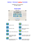
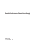
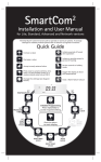
Universal Heating Controller
Installation and User Manual
for UNI/H version
Quick Guide
Increase a value.
Enter the settings menu.
Decrease a value.
Initiate or quickly override
a time program on or off
Accept a newly entered value.
Initiate a holiday period.
Cancel overtime, holiday,
edited value or current
submenu.
End overtime, holiday or reset
time logs in engineers menu.
Select Summer mode
(hot water only) and Winter
mode (heating and hot water)
Toggle the display between
time and sensor readings
Universal Heating Controller
Installation and User Manual
CONTENTS
Introduction .....................................................................…........3
1 Technical Specifications .............…............................…..….. 3
1.1 Operating Environment .................................................…..... 3
1.2 Performance Specifications .……………........................….... 3
1.3 Electrical Specifications ………………….........…………….....4
2 Installation Instructions ........................................…….....….5
2.1 Mounting the Control Assembly ..............……..……….......…5
2.2 General Wiring Specifications .........................……………….7
2.3 Wiring Connections .………………….......…...........………….8
2.4 Remote Temperature Sensor Wiring Connections….……….9
2.5 Occupancy Sensor Wiring Connections …..………………….9
3 Operating Instructions ....................….......................……….10
3.1 The buttons .......................................................………….….10
3.2 The display … .........................................................…………11
3.3 Setting User Parameters………………………………………..13
3.4 Setting the Clock ………………………………………………..13
3.5 Setting the Mode ………….…………………………………….14
3.6 Setting the Program (on / off times)……………….…………..15
3.7 Setting the Temperatures………………………………………16
3.8 Setting Summer or Winter operation..………………………...16
3.9 Extend …………………….……………………………………..17
3.10 Holiday………………….………………………………………18
3.11 Viewing info…………………………………………………… 18
3.12 Battery type and replacement………………………………..19
4 Engineer Functions ..................................................…....... 20
4.1 General Password (PIN protection).........…………………...20
4.2 Programming the engineering functions........……………….21
4.3 The Engineer Variables………………………………………..22
Introduction
This manual describes the installation and operation of the Universal Heating
Controller (UNI/H).
This control unit must be installed according to the current IEE wiring Regulations
and should include full disconnection means and fusing appropriate to the connected
loads.
Universal Heating Controller is a simple to use and flexible controller designed to
offer the energy saving features of Building Management Systems for medium and
smaller buildings.
1 TECHNICAL SPECIFICATIONS
1.1 Operating Environment
Operating temperature range:
0º C to 40º C
Operating humidity range:
0 to 90% RH.
Control IP rating:
IP30
Pollution degree:
II environment
Control safety construction:
Class II
Mains supply:
230Vac nominal, 200Vac to
265Vac actual, 50Hz.
On board supply fuse: 1AT
Rated impulse voltage: 2500V
Recommended control supply fuse:
3A
Rated impulse voltage: 2500V
Dimensions: 216mm X 124mm X
62mm
Conformities: EMC – 89/336/EEC
LVD – 73/23/EEC
1.2 Performance Specifications
An independently mounted
electronic control for surface
mounting.
Operation is by Class A software and Type
1A action.
The mains supply to the electronic
circuit is to be protected by a fuse.
Remote switch inputs will be volt free,
12Vdc/5mA
Occupancy sensor inputs are volt
free, normally closed (contacts
open on detection of occupancy) as
BW/MINI and PIR/CM.
Maximum sensor rating: 90)
Temperature sensor input is from a
thermistor sensor, as UNI/RS
(room sensor), UNI/EXT (outside
sensor), UNI/CS (clamp on
sensor), UNI/WIM (immersion
sensor probe).
3
1.3 Electrical Specifications
The power supply is SELV isolated,
therefore all remote sensor and
remote switch wiring to the control
does not need to be mains level
rated, but should be insulated to
the highest voltage present where
entering the control box.
Relay 1 is rated:
16A/240Vac resistive
6A/240Vac inductive
550W motor load
Relay 2 is rated:
16A/240Vac resistive
6A/240Vac inductive
550W motor load
0 – 10V signal:
A 0 to 10Vdc output signal is
provided for modulating valve
control. Output impedance is 50
Ohm and maximum current drive
capacity is 5mA. The output signal
is not isolated from the control
circuit but the common ground may
be Earthed.
Sensors can be sited up to 100m
from the control; the cable
may be screened to improve noise
rejection. Cable resistance must be
less than 10 Ohms to minimise
errors.
Total maximum load for relays 1
and 2 is 12A.
Relays 3 to 7 are rated:
10A/240Vac resistive
4A/240Vac inductive
370W motor load
Maximum load for each of relays
3 and 4 is 6A.
Total maximum load for relays 5
to 7 is 12A.
Where the plant has a higher
rating, it is recommended that the
relays are used to operate suitably
rated contactor relays.
4
2 INSTALLATION INSTRUCTIONS
2.1 Mounting the Control Assembly
Ensure that the controller is installed no less than 1.5m above the floor level.
The controller should be positioned to allow the user easy access to the push
buttons and to read the LCD display.
The controller can be positioned with the cable entry to the bottom or the top
depending on the cable routing.
The lid with the controller circuit board can be rotated through 180 degrees to
accommodate top or bottom cable entry.
Do not mount the controller on a warm surface or where it could be affected
by direct sunlight or other heat sources.
The mounting surface should be non-conducting or earth bonded and should
prevent access to the rear of the control.
5
The housing consists of a two
part plastic moulding held
together by four screws.
Plugs are supplied to cover
the screws following
installation.
Knockouts are provided for cable
glands to allow mains and remote
sensor and switch cables to be
fitted to the control assembly.
Knock the plastic out to
fit the glands as required. Never
leave holes that allow finger
access.
Whenever possible, keep mains wiring and signal wiring separated and use
separate knockouts for each type of wiring system. Consider the termination
points when selecting the appropriate knockouts.
6
2.2 General Wiring Specifications
A suitably qualified person must make all wiring connections.
Please refer to the following wiring connection drawing (see 2.3) and observe
the notes referring to cable type and length. Failure to follow these guidelines
may result in electrical interference or unsatisfactory operation. When making
connections to screw terminals please ensure that no more than 6mm of
insulation is stripped back and that no stray wire strands escape.
0-12V outputs, Analogue 0 – 10V output and remote switch inputs for
occupancy sensors should be connected by 0.75mm2 cable of maximum
length 100m.
The remote temperature sensors can be sited up to 100m from the control;
the cable may be screened to improve noise rejection. Cable resistance must
be less than 10 Ohms to minimise errors. Connect the screen to the ground
terminal (GND).
All sensor and signal wiring should be kept separate from mains wiring to
minimise noise pick-up.
7
2.3 Wiring Connections
External connections are by 27 screw terminals as follows:
Screw terminals are 7.5mm and 5mm spacing rising clamp style with 2.5mm² wire
entry size for power connections and with 1.5mm² wire entry size for signal
connections.
The terminal identification and description are provided below, together with the
maximum terminal capacity in mm2 (shown in brackets). Note that some terminals
may require more than one cable to be terminated, and therefore cable sizing should
be selected accordingly. The 12V dc and 0V dc terminals may require several cables
to be terminated in a separate connector, according to the number of remote sensors
required. Any series wiring for occupancy or sensor inputs should be achieved using
a separate connector.
CONTROLS SUPPLY
LIVE
NEUT
Live supply input
Neutral supply input
(2.5)
(2.5)
E stud
Earth termination point
(not shown)
(2.5)
INPUTS
S1+
S1S2+
S2S3+
S3S4+
S4S5+
S5S6+
S6-
OUTPUTS
ANO
Analogue output 0 – 10V
GND
0V dc output
12V
12V dc output
Zone 1 room sensor +
(1.5)
Zone 1 room sensor (1.5)
Zone 2 room sensor +
(1.5)
Zone 2 room sensor (1.5)
External outside sensor + (1.5)
External outside sensor - (1.5)
DHW sensor +
(1.5)
DHW sensor (1.5)
Boiler flow/Z1 occupancy+ (1.5)
Boiler flow/Z1 occupancy - (1.5)
Boiler return/Z2 occupancy+(1.5)
Boiler return/Z2 occupancy -(1.5)
(1.5)
(1.5)
(1.5)
RELAY CONNECTIONS (see table below)
R12I
Relay 1 and 2 common input(2.5)
R1O
Relay 1 output
(2.5)
R2O
Relay 2 output
(2.5)
R3O
Relay 3 output
(2.5)
R3I
Relay 3 input
(2.5)
R4O
Relay 4 output
(2.5)
R4I
Relay 4 input
(2.5)
R5O
Relay 5 output (Live)
(2.5)
R6O
Relay 6 output (Live)
(2.5)
R7O
Relay 7 output (Live)
(2.5)
Figure – Terminal connections
*NOTE: RELAYS 1-4 ARE VOLT FREE. CONNECT SUITABLE VOLTAGE TO R12I, R3I, R4I*
R12I
R1O
R2O
R3O
R3I
R40
R4I
R5O
R6O
ANO GND 12V S4+ S4- S5+ S5- S6+ S6-
S1+ S1- S2+ S2- S3+ S3-
Relay 1 - DHW valve open / contactor
Relay 2 - Mid-position valve control
Relay 3 - Boiler / contactor
Relay 4 - DHW secondary pump / contactor
Relay 5 - Zone 1 valve open / pump / contactor
Relay 6 - Zone 2 valve open / pump / contactor
Relay 7 - Heating pump / contactor
R7O
LIVE NEUT
8
2.4 Remote Temperature Sensor Wiring Connections
Universal Controller
Temperature sensor
S+ Æ +
S- Æ (Note that un-marked sensors are not polarity sensitive)
2.5 Occupancy Sensor Wiring Connections
Where occupancy detection is required, a range of BlueWave sensors are
designed for use with the Universal Heating Controller.
The preferred cable is 4-core stranded and connections will be as follows:
Universal Controller
12V
GND
S+
S-
BlueWave Sensor
+
ALM (ALARM)
ALM (ALARM)
Note – Tamper and LED terminals on the BlueWave sensor(s) are not used.
Where more than one sensor is required for a sensor input, installation should
be as above with the exception of the wiring. To use two or more sensors
connect + & - in parallel and connect ALM contacts (ALARM) in series. The
connections on different versions of sensors may vary slightly to the drawing
below:
9
3 OPERATING INSTRUCTIONS
3.1 The buttons
The ten buttons have the following functions:
Increase a value
Enter the settings menu
Decrease a value
Initiate or quickly override
a time program on or off
Accept a newly entered
value
Initiate a holiday period
Cancel overtime, holiday,
edited value or current
submenu
End overtime, holiday or
reset time logs in
engineers menu
Select Summer mode
(hot water only) and
Winter mode
(heating and hot water)
Toggle the display
between time and
sensor readings
Note if no keypad action takes place for 60 seconds, the current selection is
cancelled and the display returns to day and time and previously set operating
mode.
10
3.2 The display
During normal operation the time and day will be displayed. If the system
needs servicing then the service icon is displayed here.
The display will normally cycle through the status of each zone, showing
where appropriate the target temperature for each zone, the operating mode
and heating status.
3.3 Setting User Parameters
Press the SET button when in normal display mode allows the user to set
various parameters within the unit. Repeat presses of the SET button will
cycle through the following options:
1.
2.
3.
4.
Set Clock
Set Auto Mode
Set Time Program
Set Temperature Levels
3.4 Setting the Clock
Press the SET button. (Enter your PIN if prompted.)
The icons SET, CLOCK and OK? Will be displayed with the CLOCK icon
flashing.
Press the OK button to accept the set clock function.
The current clock setting will be displayed and one of the days will now flash.
11
Press + or - until the correct day is displayed and press OK to accept.
Next the hours display will flash.
Press + or – until the correct hours are displayed and press OK to accept.
Next the minutes display will flash.
Press + or – until the correct minutes are displayed and press OK to accept.
The controller will return to normal operation.
3.5 Setting the Mode
The Mode defines whether a zone is permanently on (ON), permanently off
(OFF), or controlled by the time program (AUTO).
Press the set button (enter the PIN if prompted) to access the SET AUTO
option. The icons SET and OK? will be displayed with the AUTO, ON and
OFF icons flashing.
Press OK to accept the SET AUTO function.
A prompt for the applied zone will appear to the right of the display, with “A”
meaning that the setting will be applied to all zones.
Use the + and – keys to select the zone to be configured, then press OK.
The current auto setting for that zone will be shown.
Use the + and – keys to cycle through the modes “ON”, OFF” or “AUTO” and
press OK to accept the required operating mode.
12
3.6 Setting the Program (on / off times)
Each zone can be programmed to be active during certain times of the day.
Three active periods can be programmed, between ON 1 and OFF 1,
between ON 2 and OFF 2 and between ON 3 and OFF 3. The second and
third on/off periods can be skipped if not required. A different program can be
set for each day of the week.
Press the set button (enter the PIN if prompted) to access the SET
PROGRAM option.
The icons SET and OK? Will be displayed with the PROGRAM icon flashing.
Press OK to accept the Set Program function.
Zone number 1 will be displayed flashing.
Use the + and – keys to cycle through to the zone which needs to be
programmed. Press OK.
The day of the week will flash (The time area will be blank) Press the + and –
keys if you want to chose another day to be programmed and press OK to
accept.
The timeslot icon [ON 1] will be displayed and the hours and minutes display
will flash. Press + or – until the required ON time is displayed. The time will
change in ten minute steps. Press OK to accept.
Press OK will advance the display as follows:
•
An ON time will advance to its corresponding OFF time. If an ON time
is programmed its corresponding OFF time must be programmed for
that same day.
•
The default value for ON2 and ON3 time is unused, “--:--“. To change
this to a usable ON/OFF slot, press the – button.
13
•
If ON2 time is set to unused, “--:--“, pressing OK will then allow you to
select a different day.
•
Similarly, if ON3 is set to unused, “--:--“, pressing OK will then allow
you to select a different day.
•
ON2 cannot be set to unused and ON3 set to used.
•
If a day, eg Saturday, does not require a program, then set ON1 time
for that day to unused, “--:--“. (Press the + button until it changes from
“23:50” to “--:--“.)
•
When the time programme for the week is completed, press OK to
review the programme or press + and – to select another zone.
Three timeslots per day are allowed for each zone, where each timeslot
includes an ON and OFF time. For heating zones, the ON 1 time is the target
time and the optimiser will switch heating on in advance aiming to achieve the
target temperature by the ON 1 time. Subsequent ON times are fixed and are
not affected by the optimiser.
Once a day’s time program has been completed the day icon will flash for the
next day.
To finish with the program settings press cancel or reset after pressing OK for
the last programmed day.
3.7 Setting the Temperatures
Target temperature levels can be programmed for each zone. During
operation the boiler, valves and pumps or contactors will operate as required
to achieve this target.
Press the set button (enter the PIN if prompted) to access the SET TEMP
option. The SET and OK? icons will be displayed, with the TEMP icon
flashing.
Press OK to accept the SET TEMP function.
14
A zone number will now be flashing to the right of the display. Use the + and –
keys to select the required zone and press OK.
A temperature level will flash in the centre of the display.
Use the + and – keys to adjust the required temperature level. The
temperature level can range from 10°C to 30°C for heating zones and 30°C to
60°C for domestic hot water (DHW). Pressing and holding a key will force an
accelerated cycle through values. Press OK to confirm the required level.
A prompt to program the next zone in sequence will now appear. Continue
programming temperature levels as required, and press the CANCEL button
when finished.
3.8 Setting Summer or Winter operation
The SUMMER/WINTER key offers a quick means to change between
providing heating and domestic hot water (winter) to domestic hot water only
(summer).
Press the SUMMER/WINTER key when in normal (winter) display mode.
The “OK?” icon will be displayed with the “HW” icon and an “S” (indicating
summer) to the right of the display.
Press OK to accept the summer setting.
When in summer mode the time display shows an “S” on the right side of the
display, along with the day and time as usual.
15
When in summer mode, press the SUMMER/WINTER key. The “OK?” icon
will be displayed with the “CH” and “HW” icons flashing.
Press OK to accept the winter setting.
3.9 Extend (Initiate or quickly override a time program on or off)
The EXTEND key can be used to provide a time limited extension to the
program for use outside normal hours, or to turn the heating system off for a
time limited period.
Press the EXTEND key to access the Extend function.
The Set, Overtime and OK? icons will be displayed with “ON” flashing in the
centre display.
Use + and – to choose between an ON overtime period (program is on for a
limited period) or an OFF overtime period (program is off for a limited period)
Press OK to select.
Now chose the zones the overtime will be applied to, using + and -. You will
first be offered the option to apply the overtime period to all zones (“A” will
flash as the zone). Enter yes to choose all zones, or use + and – to change
16
and enter “no” to go on and individually select which zones will be applied.
Press OK to select.
Enter the length of the overtime period with + and -. The time duration will
advance in units of ten minutes. The maximum overtime period is set in the
engineering functions.
Press OK to initiate the overtime period. The normal clock display will be
replaced with an overtime countdown that will show OFF OVERTIME or
ON OVERTIME and remaining overtime in minutes according to the selection
made for each zone.
While in overtime mode the extend period can be increased or decreased by
pressing the extend key. The time can be modified without having to
reprogram the extend type or applicable zones. Adjusting the time to zero will
cancel the overtime period.
An overtime period can be quickly cancelled at any time by pressing the
CANCEL or RESET key.
(It is not possible to have one zone with override on and another with override
off at the same time. The override will apply regardless of the operating mode
for each zone selected.)
3.10 Holiday
Press the HOLIDAY key when in normal display mode to set a holiday period
of a number of days. During a holiday period, all zones are off and will only be
active according to frost level settings.
Enter the length of the holiday period with + and -. The time duration will
advance in units of days, to a maximum of 99 days.
17
Press OK to initiate the holiday period. The normal clock display will now
include the holiday icon in the lower left corner, indicating that a holiday is
scheduled. The holiday will not become active until midnight.
When in an active holiday period the normal clock display will be replaced
with a holiday countdown.
While in holiday mode the holiday period can be increased or decreased by
pressing the HOLIDAY key. The number of days can be modified if required.
Adjusting the number of days to zero will cancel the holiday period.
An holiday period can be quickly cancelled at any time by pressing the
CANCEL or RESET key.
(Holiday mode is applied to all zones.)
3.11 Viewing info
When in the normal display mode the status of each of the sensor inputs can
be viewed by pressing the INFO key. Consecutive presses of the info key will
cycle through all sensors, followed by the target boiler return temperature and
the calculated minutes per degree for optimum start.
The status of PIR sensors (when the unit is configured for electric heating) will
be shown as either ON or OFF.
Temperature sensors will show the temperature reading in degrees Celsius.
The optimum start value will be shown in minutes per degrees Celsius.
The sequence of values displayed is as follows:
1
2
3
4
Zone 1 room sensor
Zone 2 room sensor
External outside sensor
Hot Eater (DHW) sensor
5
6
h
O
Boiler flow/Z1 occupancy
Boiler return/Z2 occupancy
Target boiler return temp
Optimiser: minutes per 1°C
18
3.12 Battery Type & Replacement
The real time clock and program information is battery backed up by a lithium
coin cell. When mains power is interrupted, the clock, backed by the battery,
will continue to operate normally for seven days after which it will stop. The
battery will continue to back up the program information.
The battery has a service life of approximately five years. The condition of the
battery is monitored and when replacement becomes necessary, this will be
indicated on the display. Replacement will be indicated on the display only if
mains supply is present.
To replace the battery, isolate the control from the mains electricity supply and
remove the plugs / screws securing the front panel to the rear case. Carefully
remove the panel and detach the ribbon cable from the power PCB assembly.
Remove the old battery and fit the new battery as shown in the photograph.
19
4. ENGINEER FUNCTIONS
The engineer functions allow you to program various advanced parameters.
In order to access the engineer function press and hold the + button and
press the SET button.
4.1 General password (PIN Protection)
When the engineers area is accessed, the controller will prompt you for the
engineers password; the PIN will be displayed and four zeros will be
displayed with the first zero flashing.
Press the + or – buttons until the correct first digit of the PIN code is
displayed. Press OK to enter this digit.
Once accepted the second zero will flash. Press the + or – buttons until the
correct second digit of the PIN code is displayed. Press OK to enter this digit.
The third zero will flash. Press the + or – buttons until the correct third digit of
the PIN code is displayed. Press OK to enter this digit.
Next the fourth zero will flash. Press the + or – buttons until the correct fourth
digit of the PIN code is displayed. Press OK to enter this digit.
Once the PIN code has been set and accepted, you will immediately gain
access to the control settings (explained below)
•
Access will remain available for 60 seconds after the last button press,
after which the PIN code will have to be entered again to get access to the
settings.
•
If the PIN code is not available, contact the manufacturer for the master
PIN code.
20
4.2 Programming the engineering functions
Once the PIN code has been entered the [SET] and [ENGINEER] icons are
displayed with the first parameter H1.
All engineer functions are displayed as a code in the first two digits if the
display, e.g. C1, t1, t2 and a variable in the second two digits.
Press the SET button to cycle through the engineering variables until the
desired variable is displayed.
Press OK button to accept this variable. The variable value (second two
digits) will start flashing.
Press the + or – buttons until the desired variable value is displayed.
Press OK to accept this value. The variable value will stop flashing.
Press the SET button to advance to another variable.
Pressing the CANCEL button twice consecutively, at any time while in the
engineer function, will cause the controller to exit the engineer function and
return to normal operation. Only items that have been OK’d will be changed.
If no keypad action takes place for 60 seconds while in the engineer function,
the controller will exit the engineer function and return to normal operation.
Only items that have been OK’d will be changed.
21
4.3 The Engineer Variables
Code Name
H1
Boiler On
Hours
H2
Service Hours
Properties
Default
Read
Only
Read/
Write
0000
0.0
Values
0000 to
9999
0.0 to 9.9
C1
Compensation
Type
Read/
Write
02
00 to 02
C2
Compensation
Gradient /
Electric
Heating
Setback
Read/
Write
12
00 to 20
C3
Compensation
Offset
Read/
Write
15
00 to 40
Meaning
Displays the boiler “on” hours
since the last reset.
The number of boiler “on” hours
allowed before the SERVICE
icon is displayed. The value is
given in units of 1000h.
0=Electric Heating (No
compensation)
1=Load Compensation
2=Weather Compensation
(requires outside sensor)
When C1=00 this gives the
number of degrees to set back
the room temperature when the
zone is unoccupied. Target
temperature is still used for ON1
time before setback applies.
When C1 = 01 or 02 this controls
the gradient of the target boiler
return temperature.
When C1=00 this value has no
effect.
When C1 = 01, C3 controls the
speed of response.
C4
C5
Outside
temperature
cut off
Read/
Write
Minimum
Return
Temperature
Read/
Write
18
30
10 to 25
20 to 50
When C1 = 02, C3 controls the
offset of the target boiler return
temperature.
C1 = 00, no effect
When C1=01 or 02, zone heating
is not provided if the outside
temperature is greater than this
value.
The minimum boiler return
temperature that must be
maintained during heating
periods.
22
b1
b2
b3
U1
U2
U3
U4
t1
t2
t3
F1
F2
E1
Heating start
compensation
boost %
Heating tail off
compensation
reduction %
Heating tail off
delay
Pump run on
time after hot
water
Pump run on
until return
temperature in
°C
Pump run on
time after
central heating
Minimum
boiler cycle
Maximum
overtime
Maximum
optimum start
Maximum
optimum stop
Frost
protection
enable
Frost
protection set
point
Regular run
Read/
Write
Read/
Write
Read/
Write
Read/
Write
25
10
12
10
00 to 50
00 to 50
00 to 24
00 to 99
Read/
Write
28
20 to 50
Read/
Write
06
00 to 24
Read/
Write
Read/
Write
Read/
Write
Read/
Write
Read/
Write
05
00 to 90
06
00 to 60
06
00 to 24
03
00 to 12
01
00 to 01
Read/
Write
05
00 to 20
Read/
Write
00
00 to 01
C1 = 00 or 01 this value has no
effect.
C1 = 02 Controls the percentage
boost applied to the target boiler
return temperature at the start
C1 = 00 or 01 this value has no
effect.
C1 = 02 Controls the tail off
compensation reduction.
C1 = 00 or 01 this value has no
effect.
C1 = 02 Controls the tail off delay
period in units of 10 minutes.
C1 = 00 PIR runback time in
minutes (occupancy detected
time before set back)
C1 = 01 or 02. Pump run on time
after hot water operation.
The pump runs until boiler return
temperature falls to this value.
Pump run on time after central
heating demand in units of 10
minutes.
Minimum boiler cycle in minutes.
The maximum allowed overtime
in units of 10 minutes.
Maximum optimum start time in
units of 10 minutes.
Maximum optimum stop time in
units of 10 minutes.
00 = Frost protection disabled.
01 = Frost protection enabled.
The temperature at which frost
protection is enforced, in deg.C
00= Pumps do not have regular
run.
01= Pumps have a regular run of
5 seconds every 24 hours.
23
E2
Hot water
control
Read/
Write
00
00 to 02
00=Hot water (DHW) demand is
defined by the zone 3 time
program only. Hot water demand
controls the hot water relay only
(relay 1).
Intended for immersion heater
based hot water with its own
thermostat.
01=Hot water (DHW) demand is
defined by the zone 3 time
program and the hot water
sensor. Hot water demand
controls the hot water relay and
2ndry pump relay. Intended for
independent boiler based hot
water.
E3
E4
Hot water
temperature
boost
Active zones
Read/
Write
Read/
Write
00
01
00 to 01
00 to 02
02=Hot water (DHW) demand is
defined by the zone 3 time
program and the hot water
sensor. Hot water demand
controls the hot water relay, the
boiler relay the pump relay and
the 2ndry pump relay. Intended
for single boiler system.
00= No boost of hot water
applied.
01= Hot water (DHW)
temperature set point is raised to
65 deg. C at 1am on Wednesday
to eliminate bacteria in the water.
00=Central heating zone 1
active, central heating zone 2
inactive, hot water zone 3 active.
01=Central heating zone 1
active, central heating zone 2
inactive, hot water zone 3
inactive.
02=Central heating zone 1
active, central heating zone 2
active, hot water zone 3 inactive.
03=Central heating zone 1
active, central heating zone 2
active, hot water zone 3 active.
24
E5
Slave Zone
Selection
Read/
Write
00
00 to 03
00= No zones are slaves.
01=Zone 2 is a slave with zone 1
times.
02=Zone 3 is a slave to zone 1
times.
E6
Boiler Type
Selection
Read/
Write
00
00 to 01
E7
Mixing Valve
Control
Read/
Write
00
00 to 01
S1
Temperature
offset (Zone 1)
Read/
Write
00
-5 to 05
S2
Temperature
offset (Zone 2)
Read/
Write
00
-5 to 05
S3
Temperature
offset
(Outside)
PIN Protection
Read/
Write
00
-5 to 05
Read/
Write
01
00 to 01
P1
P2
PIN Number
Read/
Write
00
0000 to
9999
P3
Factory Reset
Read/
Write
00
00 to 01
03=Zones 2 and 3 are slaves to
zone 1 times.
00=Normal boiler with separate
boiler and pump control.
01=Combi-boiler without
separate boiler and pump
control.
00=No mixing valve control.
01=Mixing valve control enabled.
The temperature reading offset
applied to S1(zone 1 room
temperature sensor).
The temperature reading offset
applied to S2 (zone 2 room
temperature sensor).
The temperature reading offset
applied to the S3 (outside
temperature sensor).
00=settings menu not protected
by PIN.
01=settings menu protected by
PIN.
The PIN number for the settings
menu.
00=do not reset all of program
and engineering data to default
settings.
01=reset all of program and
engineering data to default
settings.
25
26
27
Document reference: UNI/H ~ Universal Heating Controller Instructions Issue 1 – 7th February 2007
Chalmor Ltd, Unit 1, Albert Road Industrial Estate, Luton, , LU1 3QF
www.chalmor.co.uk Tel: 01582 748700 Fax: 01582 748748
28