1
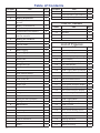
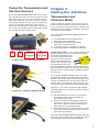
YELLOW JACKET ®
Refrigeration System Analyzer
Users Manual
UPC# 40812, 40813 and 40815
(Versions 1.06 and higher)
Note: These instructions do not cover the manifold
attached to the instrument.
Table of Contents
Chapter
1
2
3
4
5
6
7
2
Title
Pg.
Chapter
Title
Pg.
Before You Start
3
Features and Specifications
15
Contact and Safety Information
3
Instrumentation Specifications
16
Getting Acquainted
4
Warranty Policy
16
Turning the Instrument On
and Off
4
Battery Considerations
4
Keyboard Keys
5
Understanding the Displays
6
Using the Temperature and
Vacuum Sensors
7
Getting the Job Done
7
Temperature and Pressure Mode
7
List of Tables
Table
Title
Pg.
1-1
Safety Information
3
1-2
Symbols
4
2-1
Key Functions
5
6-1
Spare Parts
14
List of Figures
Vacuum Mode
9
Vacuum Sensor Calibration
10
Table
Data Logging
10
2-1
Menu Display
4
Begin Logging
10
2-2
Battery Power Symbol
5
Playback and USB Functionality
11
2-3
Low Battery Pop-up Message
5
Erase Files
11
2-4
Menu Display
6
Settings
11
2-5
System Analyzer Display
6
Refrigerant Type
11
2-6
P/T Chart Display
6
Temperature Unit
12
2-7
Vacuum Gauge Display
6
Elevation
12
2-8
Data Logging Start-up Display
6
Auto Vacuum Gauge
12
2-9
Set-Up Display
6
Power Saving Mode
12
2-10
Sensor Connections
7
Auto Power Off
12
2-11
Sensors without Boots
7
Battery Type
12
2-12
Sensors with Boots
7
Graph Type
12
3-1
First System Analyzer Display
8
Time Format
12
3-2
2nd System Analyzer Display
8
Time and Date
12
3-3
3rd System Analyzer Display
9
Refrigerant Favorites
12
3-4
Vacuum Gauge Display
9
Zero Pressure
13
3-5
Sensor Calibration Number
10
Exiting the Set-Up Display
13
4-1
Data Logging Menu
10
Settings Shortcut
13
4-2
Data Logging Start-Up Screen
10
Maintenance
13
4-3
Data Log Files
11
General Maintenance
13
5-1 (a, b)
Set-up Displays
11
Replacing the Batteries
14
5-2
Time & Date Setting Screen
12
Spare Parts
14
5-3
Refrigerant Favorites Set-up
12
Software Updates
14
5-4
Refrigerant Favorites Screen
13
Further Assistance
15
5-5
Settings Shortcut
13
Specifications
15
5-6
Battery Access
14
Safety
15
5-7
Battery Servicing
14
Title
Pg.
Chapter 1
Before You Start
Contacting Ritchie
To order accessories, receive assistance, or
locate the nearest YELLOW JACKET distributor.
Corporate Office and Mailing Address:
Table 1-1. Safety Information
Warning
● The instrument contains no internal user-
serviceable parts other than batteries that
may be accessed through the battery door.
Do not open the instrument other than opening the battery door. Have the instrument
serviced only by Ritchie Engineering Co. or
authorized service centers.
Ritchie Engineering Co, Inc.
YELLOW JACKET Products Division
10950 Hampshire Avenue South
Bloomington, MN 55438-2623 U.S.A.
Phone: (952) 943-1300 or (800) 769-8370
Fax: (800) 769-8370
E-mail: [email protected]
www.yellowjacket.com
● Do not use the instrument if it operates ab-
Safety Information
● Do not operate the instrument or service bat-
Use the instrument only as specified in this
manual. Otherwise, the protection provided by
the instrument may be impaired. Refer to safety
information in Table 1-1.
● Various refrigerants have been intentionally
A Warning identifies conditions and actions that
pose hazards to the user. A Caution identifies
conditions and actions that may damage the
instrument or the equipment under test.
● The refrigerant database in this unit may
Table 1-1. Safety Information
Warning
To avoid personal injury or death, follow these
guidelines:
● Most governments and legal authorities re-
quire that HVAC technicians be trained and
certified in the safe and proper operation of
HVAC tools, such as this instrument. Since
this tool may be connected to many types of
equipment through a limitless combination
of hoses and fittings, proper training is the
most important element of using this tool
safely.
● Read the entire Users Manual before using
the instrument.
● Use the instrument only as described in the
Users Manual, otherwise the protection provided by the equipment may be impaired.
● Do not use the instrument if it is damaged.
Before you use the instrument, inspect the
case. Look for cracks or loose components.
normally. Protection may be impaired. When
in doubt, have the instrument serviced.
● Refer to warnings supplied with batteries
acquired for use in this instrument. If the batteries are not supplied with warnings, obtain
them from the manufacturer or supplier.
teries around explosive gas, vapor, or dust.
excluded for very significant safety reasons.
Never use refrigerants in this instrument that
are not listed in the Set-up menu.
include refrigerants classified as flammable.
If such refrigerants are selected, the operator
may need additional certifications and/or
training. Consult your government and legal
authority and comply fully with all requirements.
● Always wear eye and skin protection when
working with refrigerants. Escaping refrigerant vapors will present a freezing danger.
Do not direct refrigerant vapors venting from
hoses towards the skin.
● Maximum Working Pressure: High Side: 700
psia (4.83 MPa)
● Maximum Working Pressure: Low Side: 350
psia (2.41 MPa)
● Because this instrument allows for various
inputs including electrical and mechanical,
care must be taken to observe any ways that
an electrical shock hazard could develop.
Example: Wet or humid conditions, along
with a damaged thermocouple or vacuum
sensor, could allow an electrical path across
the instrument and over wet hoses. Keep all
interconnected equipment clean, organized,
and in proper condition. Do not use the instrument if you are not qualified to recognize
potential electrical faults.
cont. next page.......
3
Table 1-1. Safety Information
Caution
To avoid damage to equipment, follow these
guidelines:
● Do not allow pressures beyond the specifications listed in this manual.
● Be aware that internal pressures can
change unintentionally when equipment is
stored with pressure in the system during
temperature changes. If sub-cooled liquid
refrigerant is trapped in a hose or manifold
with no room for expansion, it may result in
dramatic pressure variations with seemingly
small temperature changes. Pressures can
reach high enough levels to cause damage to the instrument’s internal pressure
transducers. Release liquid refrigerant from
the hoses and manifold when disconnecting
from a system.
● Refer to cautions supplied with batteries
acquired for use in this instrument.
●
Do not attempt to introduce liquid or
samples heavily laden with oil into the
instrument.
● Read and observe instructions and specifications related to the batteries used in this
instrument that may cause damage to it.
Chapter 2
Getting Acquainted
Introduction
This instrument will clearly and accurately report
critical information needed to properly service refrigeration and air-conditioning equipment. With its
many features, time can be saved and the quality
of service can be verified through data reports for
customer satisfaction. Some of the most significant features include:
● High accuracy and resolution
● Very fast and sensitive leak detection
● Robust temperature compensation with fault detection
● Data logging and downloading for reporting and
analysis
● High durability and weather-resistance
Note that these instructions do not cover the
manifold attached to the instrument.
Turning the Instrument On
and Off
Press and release the
key to turn unit on. After
the logo appears briefly, the instrument will present the main menu.
Press and hold the
unit off.
key (~two seconds) to turn
● Do not use this instrument on systems
containing leak sealing chemicals. These
leak sealants can collect and harden in the
instrument, causing permanent damage.
Table 1-2 Symbols
Important information
Power On/Off
T1
Temperature 1
T2
Temperature 2
REC
Indicates that the instrument is
recording readings (data logging)
||><||
Indicates page-by-page scrolling
mode (during data log playback)
Battery
Battery connector orientation
4
Figure 2-1. Menu Display
Battery Considerations
The instrument uses eight AA batteries. The
user may select batteries of the following types:
Alkaline, AA-Lithium, Ni-MH, Ni-Cd, Li-Pol, Li-Ion
from the Setup menu (see Chapter 5). Do not mix
battery types, including rating (i.e., do not mix four
Ni-MH rated at 1600mAh with four Ni-MH rated
at 1800mAh). Also, each battery in a set of eight
must be at the same power state, preferably fully
charged. The battery life indicator is only accurate
when the correct battery type is selected in the
SET-UP menu.
The illustration below shows three bars that indicate a fresh or well-charged battery pack. When
the battery weakens, the bars will disappear oneby-one as the battery power decays. When one
bar remains, the symbol will turn yellow. When all
bars are gone, the batteries are nearly dead and
the symbol will turn red. The unit will briefly show
a pop-up message just before the unit stores all
data and then automatically shuts off.
Maximizing Battery Life
Battery life decays fastest when the DIGITAL
MANIFOLD display is selected, the vacuum sensor is attached, and the backlight is on. Battery
life during data logging is maximized by using
high-performance batteries, detaching the vacuum
sensor (if not in use), and a short Power Saving
Mode time setting is selected.
Keyboard Keys
Figure 2-2. Battery Power Symbol
Note that pressing a key that has not been
assigned to a function will result in three, short
beeps.
Table 2-1. Key Functions
Power On/Off (see Chapter 2, Turning the Instrument On and Off).
Menu
Accesses menu of instrument
functions.
Enter
Accepts selected functions and
values.
This key will also toggle the instrument data display modes. See
Chapter 3.
Figure 2-3. Low Battery Pop-Up Message
During playback of logged data,
toggles between point-by-point and
page-by-page scrolling.
Automatic Power Off
The instrument may automatically turn off after
a period of time. The default is one hour. The
user may select other settings from ten minutes
to four hours from the Setup menu (see Chapter
5). The user may also disable this feature. The
Auto Power Off time limit is automatically disabled
during data logging and is automatically restored
once data logging has terminated.
Clear
Power Saving Mode
Hold
Freezes the data display at the
moment the key is depressed when
data is being displayed. A second
key press will return the display to
the normal, dynamic mode (not accessible during data logging).
Chart
Time
Toggles time resolution to display
more or less of the data acquisition
event, enhancing a user’s ability to
see significant events (not accessible
during data logging).
Chart
Pressure
Toggles pressure resolution to fit
analog pressure data within the
display, enhancing a user’s ability to
see significant events.
Up/Left
Assists in selection of values and
data points depending on the function feature involved (not accessible
during data logging).
The display backlight will fade, darkening the
display to save battery life if a key has not been
pressed for a set period of time. While in Power
Saving Mode, pressing any key turns the display
backlight back to full brightness. Note that
backlighting is independent from the display
brightness and contrast settings (see Chapter 5)
which do not affect battery life.
The Power Saving Mode is preset to 10 minutes.
From the Setup menu (see Chapter 5), you can
specify settings from 30 seconds to 60 minutes.
Low Battery Conditions
The unit will attempt to store all logged data if
low battery power is detected. Once the data is
stored, unit will turn off.
A single press clears the chart set
point. (See Figure 3-1, item 11)
Press and hold to clear ‘Min.’ and
‘Max.’ values. (See Figure 3-1,
item 5)
Resets vacuum timer to 0:00:00.
(See Chapter 3)
Down/
Right
5
Understanding the Displays
Figure 2-4. Menu Display
Use the ▲ or ▼ keys to scroll through the menu.
Figure 2-7. Vacuum Gauge Display
(See Chapter 3)
Press the “Enter” key to make a selection.
Figure 2-5. System Analyzer Display
(See Chapter 3)
Figure 2-6. P/T Chart Display
This display shows the “P/T” (Pressure/Temperature) chart for the refrigerant that is selected in the
“Set-Up” display. Use the ▲ or ▼ keys to scroll
through the chart. Press the “Menu” key to exit.
6
Figure 2-8. Data Logging
Start-Up Display
(See Chapter 4)
Figure 2-9. Set-Up Display
(See Chapter 5)
Using the Temperature and
Vacuum Sensors
Chapter 3
Getting the Job Done
To use the external temperature and vacuum sensors, plug them into the connectors located on the
side of the instrument. The use of rubber connector boots is optional. They will, however, increase
the weather resistance of the unit and reduce the
amount of dust that could enter at the vacuum
connector, if that boot isn’t used. When not in use,
the vacuum and USB connector openings should
be covered with the tethered plugs.
Temperature and
Pressure Mode
Note: A common mistake is to forget to zero the
pressure sensors before using the instrument for
a job, resulting in incorrect pressure readings and
calculations. See Chapter 5 - Settings, Zero pressure, for more information.
The unit will simultaneously display inputs from
four sources:
● T1 Temperature Sensor (Suction line
temperature for superheat)
● T2 Temperature Sensor (Liquid line
temperature for subcooling)
● Low Side Pressure Transducer (internal)
● High Side Pressure Transducer (internal)
T1
T2
Vacuum
(Plugged)
USB
(Plugged)
Figure 2-10. Sensor Connections
Temperature Probes – The system analyzer will
display readings from any K-type thermocouple
probe with a miniature style
connector (see picture). The
K-type is usually indicated
with a letter K on the connector. The miniature style
thermocouple connectors
have two flat blade contacts. The two blade contacts are different widths to ensure proper polarity.
Plug the blade contacts into the matching slots in
the analyzer.
Your system analyzer includes a pair of K-type
bead thermocouples. To measure a surface temperature, the bead must be held firmly against the
surface. Insulating tape can be used to hold the
bead in place. The insulation will prevent the surrounding air from affecting the bead temperature.
Figure 2-11. Sensors without Boots
Figures 3-1, 3-2, and 3-3 show the three digital
manifold displays for monitoring system charging
and operation.
● The first display (see Figure 3-1) presents
all available data outputs including XY
Time-Pressure charting.
● The second display (see Figure 3-2) is the
same as the first except for the exclusion of
the Temp-1, Temp-2, vapor (Low sat.) and
liquid (High sat.) saturation points.
● The third display (see Figure 3-3) is the same
as the first except for the exclusion of the XY
Time-Pressure charting.
Once the default digital manifold display has been
selected from the main menu, pressing the “Enter”
key will advance through all three displays.
Figure 2-12. Sensors with Boots
7
While using any of the digital manifold or
vacuum gauge display screens, press the
UP/LEFT key to activate a pop-up screen
where options can be changed using the
UP/LEFT and DOWN/RIGHT keys. Press
the MENU key to save the selections and
exit the pop-up screen.
9
Superheat: The calculated superheat for
the selected refrigerant.
Subcool: The calculated subcooling for
the selected refrigerant.
Figure 3-1. First System
Analyzer Display
1
Date and Time. (See Chapter 5 to set).
2
Pressure units. While using any of the digital
manifold or vacuum gauge display screens,
press the UP/LEFT key to activate a pop-up
screen where options can be changed using
the UP/LEFT and DOWN/RIGHT keys.
Press the MENU key to save the selections
and exit the pop-up screen.
3
Refrigerant type. While using any of the
digital manifold or vacuum gauge display
screens, press the UP/LEFT key to activate
a pop-up screen where options can be
changed using the UP/LEFT and DOWN/
RIGHT keys. Press the MENU key to save
the selections and exit the pop-up screen.
4
Battery strength. (See Chapter 2 for battery
considerations).
5
The minimum and maximum pressures
encountered since the memory was last
cleared. (“Clear” key - typical for high and
low sides).
6
Set: The pressure represented by the center
horizontal line on both charts.
NOTE: These calculations are based
on the measured pressures and
temperatures.
10
Charted pressure
11
Time indication (cursor)
12
Seconds per samples (sample interval).
Use the “Chart Time” key to toggle this
value through the available settings.
A small number will show rapid pressure
changes by displaying a short period of
time (‘zoom in’). A large number will show
only slower pressure changes by displaying a larger period of time (‘zoom out’).
13
Pressure scale range. Use the “Chart
Pres.” Key to toggle pressure resolution
to fit analog pressure data within the
display, enhancing a user’s ability to see
significant events. A small range will show
small pressure changes (‘zoom in’). A
larger range will show only larger pressure changes (‘zoom out’).
14
Left Side: Suction pressure (‘Low Side’)
Right Side: Discharge pressure
(‘High Side’)
Crs: (Cursor) The charted pressure marked
by the vertical line on both charts.
7
Left Side: Vapor Saturate. The vapor saturation temperature for the selected refrigerant.
(Also known as dew point)
Right Side: Liquid Saturate. The liquid saturation temperature for the selected refrigerant. (Also known as bubble point)
8
Temp-1 (T1): The temperature indicated by
the T1 thermocouple. (For proper superheat
measurement, the T1 probe should be measuring the suction line temperature.)
Temp-2 (T2): The temperature indicated by
the T2 thermocouple. (For proper subcooling measurement, the T2 probe should be
measuring the liquid line temperature.)
8
Figure 3-2. 2nd System Analyzer Display
1
Pressure units. While using any of the
digital manifold or vacuum gauge display
screens, press the UP/LEFT key to activate
a pop-up screen where options can be
changed using the UP/LEFT and DOWN/
RIGHT keys. Press the MENU key to save
the selections and exit the pop-up screen.
2
Discharge pressure (‘High Side’).
3
When data recording is activated, this
indicator will gradually change from red
to blue indicating the size of one page of
data. During playback, it will help the user
to decide whether to move through the
data slowly or page-by-page. Adjusting the
sampling rate will affect the amount of data
on each page.
4
Vacuum reading. The message “Out of
range” will appear until the vacuum reaches
25,000 microns.
5
Elapsed time display. Press “Clear” to reset
counter to 0:00:00.
6
Vacuum Units. Vacuum readings can be
displayed in Microns, mTorr, Torr, mmHg,
mBar, KPa, and Pa.
Figure 3-3. 3rd System Analyzer Display
Vacuum Mode
Note: If you are using a new vacuum sensor for
the first time, the vacuum sensor calibration number must be entered. The instrument will report
incorrect data if this is not done. Go to ‘Vacuum
Sensor Calibration Utility’ further down in this
chapter for instructions.
The instrument can simultaneously use display
inputs from two sources:
If it is desirable to match the pressure units
with the vacuum units, the pressure units
must be selected before proceeding with
vacuum procedure.
● Vacuum Sensor
● Internal Pressure Transducers
Note: Although the internal pressure transducers
are primarily used for positive pressures, they also
give a helpful indication of vacuum activity before
the vacuum sensor indicates values in the ranges
that are typical when operating vacuum pumps.
This screen can be accessed from the main menu,
“Vacuum Gauge” selection, or the “Digital Manifold”
screen by simply plugging in a vacuum sensor if
the “Auto micron meter” is set to “ON”. (See “Settings - Auto Vacuum Gauge” in the Setup menu.)
While using any of the digital manifold or
vacuum gauge display screens, press the
UP/LEFT key to activate a pop-up screen
where options can be changed using the
UP/LEFT and DOWN/RIGHT keys. Press
the MENU key to save the selections and
exit the pop-up screen.
7
When recording is activated, the sampling
rate is displayed here. See “Chapter 4 –
Data Logging” to set the sampling rate.
8
The minimum and maximum pressures
encountered since the memory was last
cleared (“Clear” key). (Typical for high and
low sides.)
9
Left Side: Suction pressure (‘Low Side’).
Press the UP/LEFT key to activate a popup screen where options can be changed
using the UP/LEFT and DOWN/RIGHT
keys. Press the MENU key to save the
selections and exit the pop-up screen.
Figure 3-4. Vacuum Gauge Display
9
Vacuum Sensor Calibration Utility
Whenever a new vacuum sensor is used, the sixdigit calibration number printed on the side of the
vacuum sensor must be entered. At the screen
shown in Figure 3-4, press and hold the “ENTER”
key. A small pop-up window will appear where
the elapsed time usually appears. The 6 digit
number displayed is the sensor calibration number currently in memory. These digits need to be
changed to match the number on the new sensor.
The white highlighted digit indicates the digit being
edited. Use the UP/DOWN buttons to change the
highlighted value. When the highlighted value
matches the digit on the sensor label, press the
ENTER button to move to the next digit position.
Repeat until all 6 digits match the digits on the
sensor label. When the sensor number is properly
entered, press the CLEAR button. The sensor
number field will disappear and the elapsed time
field will reappear.
The instrument is
now ready for use
with the new sensor. Calibration
Number
Figure 3-5. Sensor Calibration Number
Connect the gauge to a dry part of the system.
The sensor will not work if it becomes filled with
system oil. When the pressure falls into the readout range, the numeric readout will appear.
The vacuum sensor requires approximately 30
seconds of operating (warm-up) time before the
readings are accurate.
Before data logging, verify that the units (temperature, pressure, vacuum) are set to the desired
values. They cannot be changed when data
logging is active.
Figure 4-1. Data Logging Menu
Begin Logging
To activate data logging, select the BEGIN LOGGING option from the main Data Logging menu.
The data logging start-up screen will appear,
allowing you to select the sampling rate. The
sampling rate defines how often readings will
be stored. This screen also shows the available
data logging memory and the calculated time limit
(based on the current sampling rate).
When data logging, the sampling rate will dictate
the chart time setting on the Digital Manifold
screen.
Tips for avoiding sensor contamination
● Inspect fitting for signs of oil before connecting
the 69086 vacuum gauge sensor.
● Keep the sensor vertical when possible.
● Connect the gauge directly to the system,
away from the pump.
● Isolate the pump from the system (and the
gauge) with a valve before turning the pump
off. This is very important when the gauge is
mounted near the pump.
Chapter 4
Data Logging
Introduction
Data simultaneously generated by the temperature and pressure inputs and vacuum sensor may
be stored in the instrument’s memory for viewing
later via the instrument’s PLAYBACK mode or by
downloading the data to a PC.
10
Figure 4-2. Data Logging
Start-Up Screen
After selecting the sampling rate and pressing
ENTER, the digital manifold screen will appear as
usual. When the instrument is logging data, the
REC icon will flash at the top of the screen and
the red indicator light next to the keypad will flash
periodically.
Playback and
USB Functionality
Saved data log files can be viewed using the
“Playback” option. In Playback mode, the digital
manifold screen will appear just as it did during
the logging process. Use the <> buttons to scroll
through the recorded data. As you scroll, the
date, time, pressures, temperatures, and charts
will change to match the stored values. To scroll
faster, use the ENTER key to switch to page by
page scrolling (indicated by ||<>|| icon). Pressing
ENTER again will switch back to the slower point
by point scrolling.
Instructions for utilizing the USB functionality are
supplied with the software which is available at
www.yellowjacket.com/sa.
Chapter 5
Settings
Introduction
This following display presents the instrument
settings that may be changed by the user. Use the
▲ or ▼ keys to scroll through the settings. Press
the “Enter” key to select a setting for modification.
The various setting options will then be available
by using the ▲ or ▼ keys to scroll through the
options. Once the desired option is displayed,
press the enter key to activate it and return to the
list of settings.
Note that data log files, whether viewed on the
analyzer (as shown in Figure 4-3) or on a PC,
will always be identified by the date and time
when the recording was started. Keeping track
of the dates and times of your service jobs and
your recordings will allow for easier playback and
reporting at a later time.
Figure 5-1a. Set-Up Display
Figure 4-3. Data Log Files
Erase File
Use the arrow keys to highlight the data file to be
erased. Press clear to erase.
Erase All Files
Press clear to erase all data files.
Figure 5-1b. Set-Up Display
Refrigerant Type
The proper refrigerant type must be entered in this
field in order to get accurate saturation temperatures and superheat/subcooling calculations. Your
system analyzer is pre-loaded with an extensive
list of refrigerants, identified by their official
ASHRAE numbers. This list of refrigerants can be
updated. See our website at www.yellowjacket.
com/sa for more information about updating the
refrigerant list.
11
Warning
The refrigerant database in this unit may
include refrigerants classified as flammable.
If such refrigerants are selected, the operator
may need additional certifications and/or
training. Consult your government and legal
authority and comply fully with all requirements.
Note: As you scroll through the list that the names
of flammable refrigerants are highlighted with
a red background. If a flammable refrigerant is
selected, a warning message will appear. This
warning message must be acknowledged before
proceeding. Refrigerants that do not have ASHRE
designations (if any) are designated with abbreviated trade names.
Temperature Unit - Select Fahrenheit
(F) or Celsius (C) degrees.
Elevation - For accurate refrigerant PT
data and psia calculations, the operating elevation
must be entered. The more accurately you set the
elevation, the more accurate your readings will be.
Remember to change the elevation setting when
your job takes you to higher or lower elevations.
The factory default is zero (sea level).
key. After setting each component, the values are
accepted by, once again, pressing the “Enter” key.
The changes may be discarded by pressing the
“Menu” key while the pop-up window is active.
Figure 5-2. Time & Date Setting Screen
Refrigerant Favorites
This feature allows customization of the refrigerant list so only the refrigerants likely to be used
will be visible in the selection list. Refrigerant
favorites can be changed at any time by going to
the SET-UP menu (second page) and selecting
“Refrigerant Favorites”.
Auto Vacuum Gauge - Choose
from “ON” or “OFF” (see Chapter 3 - Vacuum
Mode).
Power Saving Mode - Choose
from the available values (discussed in Chapter
2 – Battery Considerations – Power saving mode).
Auto Power Off - Choose from the
available values (see Chapter 2 – Battery Considerations – Auto power off).
Battery Type - Choose from the available types.
Graph Type - Choose from the available
types.
Time Format - Multiple date display
formats are supported. This setting will determine
how dates are displayed on the instrument. The
factory default is MM/DD/YY.
Time and Date
These settings are modified in a slightly different
manner: Selecting this setting for modification
will open a pop-up window. Each component of
the time and date values may be changed by
using the ▲ or ▼ keys to scroll though them. To
advance to the next component, press the “Enter”
12
Figure 5-3. Refrigerant Favorites Set-up
The refrigerant favorites screen will appear, giving
several options. Favorite refrigerants will be identified with the standard blue or red background
colors. Refrigerants that are not favorites will be
identified with a grey background color.
● The CLEAR button will clear all favorites
except the currently active refrigerant shown
at the top of the screen.
● The HOLD button will set all refrigerants as
favorites.
● Use the UP/LEFT or DOWN/RIGHT buttons to
scroll through the refrigerant list. The yellow
underline will identify the location in the list.
To change a favorite, identify it with the yellow
underline, and press the ENTER button. The
ENTER button will either remove the refrigerant as a favorite by turning it grey, or make it a
favorite by turning it red or blue.
● The MENU button will close the refrigerant
favorites screen, saving changes.
.
Chapter 6
Maintenance
Introduction
Basic operator maintenance is covered in this
chapter. For more extensive maintenance and
for repair, contact Ritchie Customer Service. See
Chapter 1 for contact information.
Figure 5-4. Refrigerant Favorites Screen
Zero Pressure
The “Zero pressure” setting changes the pressure
reading from whatever the unit is reading to zero.
Selecting this setting for modification will open a
pop-up window with further instructions. Verify that
manifold pressures have been released before
performing this procedure.
Exiting the Set-Up Display
To exit the Set-up display, press the “Menu” key.
Settings Shortcut
While using any of the digital manifold or vacuum
gauge display screens, press the UP/LEFT key
to activate a pop-up screen where options can be
changed using the UP/LEFT and DOWN/RIGHT
keys. Press the MENU key to save the selections
and exit the pop-up screen.
General Maintenance
Since this instrument may be used in the presence of a wide range of chemical liquids and vapors, it is recommended that the case be cleaned
fairly often with a damp cloth and mild detergent
such as dish soap.
If the unit encounters enough exposure to liquid
chemicals that the chemical wicks between the instrument boot and the case, immediately remove
the boot and clean the case as described above.
The rubber boot may be immersed in soapy water
to clean it.
Although the display has a tough, hard-coated,
protective lens, clean the lens carefully, since
display clarity is a critical component of this instrument:
● Normally, the lens can be cleaned as one
would clean plastic eyeglass lenses: Use
a soft, 100% cotton or microfiber cloth and
water or eyeglass lens cleaning solution. Do
not use paper products.
● If the lens is very dirty, generously soak a soft
cloth with warm, soapy (dish soap) water and
place the cloth for a couple of minutes over
the lens to loosen any stubborn dirt. Wipe off
excess water with a clean, less dampened,
100% cotton or microfiber cloth, and complete
the cleaning using the normal lens cleaning
method described above.
● If a non-water-soluble substance adheres to
Figure 5-5. Settings Shortcut Screen
the lens, soak a small piece of soft cloth with
kerosene and place the cloth for a couple of
minutes over the substance to loosen it. Gently dab the loosened substance with clean,
less kerosene-dampened pieces of 100%
cotton cloth until the substance is lifted. Allow
to dry and then complete the cleaning using
the normal lens cleaning method described
above.
13
Replacing the Batteries
The main batteries will need to be replaced on
a routine basis. Battery performance issues are
discussed in Chapter 2. The coin cell battery
maintains the time and date information. It may
need to be replaced once or twice in the life
of the instrument. To exit the Set-up display, press
the “Menu” key.
Turn the unit off. Rotate the hook (1) out of the
way of the battery door. Unscrew the battery door
thumbscrew (2) and remove the battery door. Lift
the battery pack out somewhat to allow access to
the battery connection (3). Reconnect the battery
pack. Tuck the battery harness to the side of the
battery compartment as shown if Figure 6-2 as
the battery assembly is lowered into the battery
compartment.
Coin Cell Battery
If the unit is not maintaining the correct time and
date, follow the instructions above to remove the
main battery pack and expose the coin cell battery
through an access hole in the floor of the battery
compartment. Using a tool such as a small screwdriver, deflect the battery to the side until a corner
of the battery springs up slightly. It may be lifted
out of the battery socket at this point. Reverse this
procedure to install the fresh battery.
Figure 5-6. Battery Access
Spare Parts
Spare parts are listed in Table 6-1. See Chapter
1 for contact information. See the included TITAN
manifold instructions for manifold-related spare
parts.
Table 6-1 Spare Parts
Figure 5-7. Battery Servicing
Main Batteries
See Chapter 7 for battery type specifications.
UPC#
Description
40819
Vacuum Sensor Cordset
40820
Battery Holder, ‘AA’ Size, 2x4
40821
System Analyzer Instrument Boot
40823
System Analyzer Battery Door
40824
System Analyzer Bumper,
Plugs, & Sensor/Probe Boots
40827
USB cable
40828
General Purpose “K-Type” Probe
(4M)
69218
General Purpose “K-Type” Probe
(1M)
69087
Vacuum Sensor
Warning
14
Because this instrument allows for various
inputs including electrical and mechanical,
care must be taken to observe any ways that
an electrical shock hazard could develop.
Example: Wet or humid conditions, along with
a damaged thermocouple or vacuum sensor,
could allow an electrical path across the instrument and over wet hoses. Keep all interconnected equipment clean, organized, and in
proper condition. Do not use the instrument
if you are not qualified to recognize potential
electrical faults.
Software Updates
Details related to software updates are available
online at www.yellowjacket.com/sa or by contacting Ritchie Engineering. See Chapter 1 for contact
information.
When Further Assistance
is Needed
If this manual does not include information needed to resolve any difficulty you may experience:
1.
2.
3.
4.
Examine the instrument for any cracks
or other damage. It may be necessary to
remove the boots and battery door for a
complete inspection. If damage is found,
contact Ritchie Engineering. See the
contact information in Chapter 1.
Replace the sensors, probes, and/or
batteries.
Additional technical information may be
available at www.yellowjacket.com/sa.
It may be necessary to return the instrument to Ritchie if the information in this
manual and the help provided here does
not resolve the issue. If this is the case,
determine the version and serial numbers
for your instrument by accessing the
set-up screen. If the unit is not functional,
the serial number is printed on the floor of
the battery compartment. After you have
secured your version and serial number,
see the contact information in Chapter 1
to obtain an RMA number and arrange for
service. For warranty information, please
see the warranty listed at the end of this
Users Manual.
Chapter 7
Specifications
Safety
Maximum Liquid and/or
Vapor Pressure
High side: 700 psia
Low Side: 350 psia
Physical Specifications
Operating
Temperature
-4 to 122°F (-20 to 50°C)
Storage
Temperature
-20 to 170°F
Size
8.3” wide x 6.7” tall x 3.6” thick
(21 x 17 x 9 cm), manifold
excluded
Weight
3.2 lbs (1.45 kg), manifold
excluded
Display unit
Digital color TFT display with
adjustable brightness and contrast behind anti-glare, scratch
resistant, protective lens
Features
Display
Graphics
Digital/analog redundancy for
pressure values; adjustable
chart resolutions to display
more or less data; three screen
layouts to facilitate various
viewing distances
Superheat
and Subcool
Automatically calculated
Max.
and Min.
Pressures
Displays and records the maximum and minimum
pressures
Hold
Function
Holds current reading and
scrolls back to past readings
Refrigerant
Database
84 NIST refrigerant profiles
included; upgradeable
Data
Logging
Adjustable time intervals from
0.1 to 10 seconds; minimum
of 24 hours at 1.0 second
intervals
Computer
Interface
Downloads data log files for
equipment performance reports
via USB port
Real-Time
Clock
Real-time clock for time and
date stamping of equipment
performance reports
Temperature
Sensors
Two, temperature compensated, continuity fault
detecting, K-type temperature
sensor ports
Vacuum
Sensor
Full scale via pressure transducers and micron gauge; Proprietary sensor: part # 69087
Pressure
Transducers
Two transducers plumbed to
manifold
Manifold
Mates with TITAN 4-Valve
Manifold
Pressure
Zeroing
Press key in setup menu to
zero
Elevation
Enter elevation in setup menu
for psia compensation
PT Chart
Reference
Screen
All installed refrigerant
profiles may be displayed
Batteries
(Main)
AA size (Quantity: 8); Alkaline,
NiCd, NiMH, A-A Lithium, Li
Ion, Li Pol; One day of continuous operation when using fresh
alkaline batteries or healthy
rechargeable batteries
Battery
(Coin Cell)
Coin type lithium clock battery for maintaining time and
date: Panasonic CR2032 or
equivalent.
Compensation
15
Features, cont.
Instrumentation
Specifications
Housing
Highly weather resistant; glassfiber reinforced, engineering
grade thermoplastic
Hook
Integral hook swivels 360° and
stows when not used
Pressure
Sensing
Resolution
Low side: 0.1 psi, 0.01bar,
1kPa, 0.01MPa, 0.01kg/cm²
Leaks
Due to high accuracy and resolution of the pressure transducers, leaks in equipment can be
quickly sensed
Pressure
Sensing
Accuracy
0.5% of full scale at 25ºC
High side: 0.1 psi, 0.01bar,
1kPa, 0.01MPa, 0.01kg/cm²
1% of full scale 55ºF to 130ºF
2% of full scale -40ºC to 120ºC
Working
Pressure
Low side: 0 – 350 psia
Proof
Pressure
Tolerable pressure without
internal damage
High side: 0 – 700 psia
Low side: 1000 psi
Warranty Policy
High side: 1000 psi
The YELLOW JACKET® Refrigeration System
Analyzer from Ritchie Engineering Company,
Inc. is guaranteed to be free from material and
workmanship defects for a period of two years.
All other YELLOW JACKET® products included
in this package are guaranteed to be free from
material and workmanship defects for a period of
one year. These guarantees do not cover products that have been altered, abused, misused or
improperly maintained.
Not all catalogued products are stocked and eligible for return. Please check with your YELLOW
JACKET representative or the factory for more
information.
All returns must have an RGA number and proof
of purchase/copy of invoice. Please obtain an
RGA number from Ritchie Engineering Customer
Service by calling 800-769-8370.
All returns must be pre-paid.
Burst
Pressure
Tolerable pressure without loss
of seal
Low side: 1500 psi
High side: 1500 psi
Temperature
Sensor Range
(Instrument)
-100°F to 600°F
Temperature
Display
Resolution
0.1°F or °C
Temperature
Accuracy
(Instrument)
±1.8°F (±1°C)
Vacuum
Display
Resolution
Shows two most significant
digits in microns (25xxx10xxx, 99xx-10xx, 99x-10x, 9910); other units - direct conversions from the micron value
Vacuum
Accuracy
20% of reading
Ritchie Engineering Co., Inc.
YELLOW JACKET Products Division
10950 Hampshire Avenue South
Bloomington, MN 55438 U.S.A.
Phone: (800)769-8370 or
(952)943-1333
Fax:
(800)322-8684
E-mail: [email protected]
Web: www.yellowjacket.com
©2009 Ritchie Engineering Co., Inc.
16
Printed in USA
P/N 500943_B