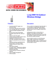
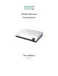
Download User`s Manual by clicking here.
Transcript
Ether Path - X 4 S erial S e rver User’s Guide Revised April 5, 2012 Firmware Version 1.09 FCC Statement This device complies with the limits for a Class B digital device, pursuant to Part 15 of the FCC rules. Operation is subject to the following two conditions: (1) This device may not cause harmful interference. (2) This device must accept any interference received, including interference that may cause undesired operation. Copyright 2006. All rights reserved. Version 1.0 All trademarks and trade names are the properties of their respective owners. TABLE OF CONTENTS FCC Statement...............................................................................i Chapter 1 Introduction..............................................................1 EtherPath Functions.............................................................1 Client/Server Mode.......................................................................1 Server Mode..................................................................................2 Point-to-Multiple-Point (EtherModem) Mode...............................2 Reverse Telnet (Telnet Client) Mode............................................2 Other Features......................................................................2 Multiple Ports................................................................................2 Automatic Connection...................................................................2 AT Commands..............................................................................2 Connection Recovery....................................................................2 Protocol Conversion......................................................................3 Configuration Security..................................................................3 Upgradeable Firmware..................................................................3 On-board Tools.............................................................................3 Physical Details....................................................................4 Front Panel....................................................................................4 Rear Panel.....................................................................................5 BottomRed LED............................................................................5 Configuration Switches .......................................................6 Switch 1........................................................................................6 Switch 2........................................................................................6 Switch 3........................................................................................6 Switch 4........................................................................................6 LED Indicators.....................................................................6 Rear Panel LED Indicators............................................................6 Front Panel LED Indicators..........................................................8 Front Panel Port LED Indicators...................................................8 Package Contents.................................................................9 Software Requirements ........................................................9 Chapter 2 Installation..............................................................10 Overview............................................................................10 Quick Start..........................................................................10 Installation..........................................................................10 1. Configure the EtherPath’s IP address......................................10 2.Connect the Ethernet Cable......................................................11 3.Verify the IP Address Configuration........................................12 4. Enter Your Configuration .......................................................13 5. Minimum Configuration..........................................................13 i Help Screens and Field Edits............................................13 Chapter 3 The Configuration Process....................................15 Overview............................................................................15 Using the Configuration Flexibility....................................15 Configuration Process Examples .......................................16 Make configuration changes, test them with Activate, then save them with Save. ..............................16 Make configuration changes, save them, reset to activate the changes....................................................16 Transfer a saved configuration to the EtherPath, save it, reset the EtherPath to activate the changes.....16 Note regarding saved configurations...........................................16 .................................................................................16 Chapter 4 Terminal/Telnet Configuration..........................................................17 Overview............................................................................17 Terminal configuration requires the following:...........................17 Procedure....................................................................................17 Telnet Configuration..........................................................18 Terminal/Telnet Interface...................................................19 Entering Data..............................................................................19 Menu Options.....................................................................19 Main Menu Option 1. Setting LAN properties................................................................19 1. IP Address...............................................................................20 2. Subnet Mask............................................................................20 3. Gateway IP Address................................................................20 4. TCP Tx Timeout......................................................................20 5. SNMP Enable..........................................................................20 6. Web Setup Enable...................................................................20 This option controls whether the Etherpath's web server (which allows web configuration) to work or not. If you select disable, and activate changes, you will no longer be able to configure via the web interface. You can always configure via the serial port Serial3, but you need physical access to the unit for serial configuration as you need to change a switch and reboot............20 7. Web Server Port......................................................................20 8. Telnet Setup Enable.................................................................20 This option controls whether the Etherpath's telnet setup server waits for a user to setup the Etherpath X4 via telnet or not. If you select disable, and activate changes, you will no longer be able to configure via the telnet interface. You can always congigure via the serial port Serial3.................................................20 7. Telnet Setup Port.....................................................................20 Main Menu Option 2. Set Admin Username and Password............................................21 Main Menu Option 3. Set Serial Port Data.....................................................................21 Flow Control...............................................................................21 Baud Rate....................................................................................22 ii Introduction Parity...........................................................................................22 Data Bits......................................................................................22 Stop Bits......................................................................................22 DCD Input Control......................................................................22 Client Dial Mode.........................................................................22 Set port dialing mode [AT Dial Hardware, (DCD) Dial, or Nailed Up] In AT dial mode, modem-like AT commands are used to connect to a remote server. In DCD dial, the client automatically connects to the remote server when the DCD signal goes high. In nailed-up mode, the DCD signal is ignored, and as soon as the client is activated, it connects to the remote server.. .22 Mode...........................................................................................22 Client's Remote IP Address.........................................................22 Server Ethernet Port....................................................................22 Main Menu Option 4. Advanced Configuration Screen..................................................23 1. Transmit Timer........................................................................23 M. Timer Mode...........................................................................23 2. Block Size...............................................................................24 3. Flow Control OFF Buffer Level..............................................24 4. Flow Control ON Buffer Level................................................24 5. Line_Terminator_Character.....................................................24 6. Transmit_on_LT_Char............................................................24 7. Server End-of-Line Filter........................................................24 8. Client Local Character Echo....................................................24 9. Keep-Alive Frequency............................................................24 Setting this parameter to a non zero value will enable a Keep-Alive feature in the Unit. When the Unit is in Client mode, it will send Keep-Alive messages to the server at the specified frequency when the link between the client and server is idle. When the Unit is in Server mode, it will close the connection if the link is idle for more than 3.5 times the Keep-Alive Frequency. The Telnet modes work differently: the Server end sends Telnet NOPs, and the Client end times out. [0=OFF, 1-32767 seconds].....................25 Main Menu Option 5. Display Settings...........................................................................26 Main Menu Option 6. Reset Configuration to Default....................................................27 Main Menu Option 7. Save and Exit...............................................................................27 Main Menu Option 8. SNMP Configuration...................................................................27 Contact Person............................................................................27 Device Name...............................................................................27 Physical Location........................................................................27 SNMP Community......................................................................27 Main Menu Option 9. Exit without Saving.....................................................................28 Chapter 5 Web-Based Configuration.....................................29 Overview............................................................................29 Administrative Maintenance...............................................30 Maintenance.......................................................................30 Actions................................................................................30 iii Notes...........................................................................................31 Tools...................................................................................31 Activate Changes................................................................32 Notes...........................................................................................32 Store Configuration............................................................33 Notes...........................................................................................33 Chapter 6 Operation................................................................34 Overview............................................................................34 Client/Server Point-to-Point (Nailed-Up) Mode...............34 Server Mode.......................................................................35 Client/Server Point-to-Multiple-Point (EtherModem) Mode35 Client (Reverse Telnet) Mode............................................36 Method 1 (ATD dial mode).........................................................36 Method 2 (Hardware Dial mode).................................................36 Chapter 7 Configuration Security...........................................37 Overview............................................................................37 Level 0: ............................................................................37 Level 1:...............................................................................37 Level 2:...............................................................................37 Level 3:...............................................................................38 Chapter 8 Troubleshooting......................................................39 Hardware Problems............................................................39 Can't Connect via the LAN................................................40 Other Problems...................................................................41 Checking Device Operation...............................................42 Appendix A Specifications..........................................................43 EtherPath - X4 Specifications............................................43 Appendix B Port Pinout and Cables..........................................44 RS-232 PIN Assignments...................................................44 Control Signal Operation....................................................44 DTR.............................................................................................44 Receive Data...............................................................................44 Transmit Data..............................................................................44 DCD............................................................................................44 Signal Ground.............................................................................44 DSR.............................................................................................45 RTS.............................................................................................45 iv Introduction CTS.............................................................................................45 RS-422 PIN Assignments RJ-45 Connector......................45 RS-422 Port Operation.......................................................45 Transmit Data (TXD-A), PIN 1...................................................45 Transmit Data (TXD-B), PIN 2...................................................45 Receive Data (RXD-A), PIN 3....................................................45 Receive Data (RXD-B), DCD Input............................................46 CABLES.............................................................................46 To PC 9-pin COM: port..............................................................46 EtherPath-X4 to PC crossover ethernet cable..............................46 .................................................................................46 Appendix C Programming..........................................................47 Introduction........................................................................47 Description and Behavior...................................................47 Ports used by the EtherPath................................................47 Server Mode.......................................................................48 Transmit Conditions....................................................................48 Locking Avoidance Mechanism.........................................48 When in Raw Server mode:.........................................................48 Application Notes...............................................................49 Appendix D AT Command Summary........................................50 AT Commands....................................................................50 AT Command Responses...................................................50 AT Command Operation ...................................................50 Appendix E Open Source Software Information......................51 Introduction........................................................................51 Obtaining the Source Code.................................................51 v Chapter 1 Introduction This chapter provides an overview of the EtherPath's features and capabilities. C ongratulations on the purchase of your new EtherPath X4 serial server. The EtherPath is a versatile product that enables serial communications devices to operate via Ethernet. It is designed to easily connect up to four serial port devices to your network. A remote PC or other serial device can then be used to monitor, configure, manage and send or receive data to the serial port devices through the LAN/WAN. The EtherPath can receive data from any asynchronous serial device, convert the data to a valid IP packet, and transmit that data over the LAN/WAN. Serial devices can then be accessed from anywhere on your LAN/WAN by any workstation computer running telnet, dedicated software, or COM: port redirection software. Two EtherPaths may be used in “nailed-up” mode to build a “RS-232 path” through the WAN/LAN. Multiple EtherPaths may be connected via Ethernet by using them in Point-to-Multiple point "AT Dial " mode. The EtherPath-X4 provides four independent serial ports, each accessible using the same IP address and different, configurable port numbers. Some serial port devices in common use are Bar Code Readers, UPSs, SCADA RTUs, security alarms, access control devices, timeclocks, POS terminals, and multiplexers. For easy connection to your LAN, the EtherPath supports both 10BaseT and 100BaseT connections. EtherPath Functions The EtherPath can be used in several modes – simple Client/Server or Server, as illustrated below, point-tomultiple-point (EtherModem) Client/Server, and reverse telnet Client. These modes are described below. Figure 1: Modes of Operation Client/Server Mode In this mode, two EtherPaths are used. Both are connected to serial RS-232 devices. This is termed a “Nailed-Up” connection. The "Client" EtherPath will automatically establish a connection to the "Server" EtherPath upon powerup. 1 EtherPath-X4 User’s Guide The device on one EtherPath communicates with the other serial port device as if it was directly connected via a serial port cable. The EtherPaths and the LAN are completely transparent to PC application and serial port device. Server Mode This mode requires only a single EtherPath. The EtherPath is connected to the serial port device, and to the LAN. Users on the LAN can then connect to the serial port device and communicate with it via Telnet, using any assigned IP and port address. Most LAN connected workstations provide support for communication via Telnet. A special-purpose utility program or port redirector program may be used instead of Telnet, or the user may create custom software using Visual Basic, C++, or other network programming tools. By using port redirection, the EtherPath may function as a remote serial port on a PC. Point-to-Multiple-Point (EtherModem) Mode Point-to-multiple-point (EtherModem) operation allows a single EtherPath running in client mode to connect to multiple servermode EtherPaths, one at a time, under the control of the attached RS-232 device. The client operates similar to a modem with “AT” dialing enabled. The attached device treats the EtherPath as if it was a modem, using remote IP addresses instead of telephone numbers. Reverse Telnet (Telnet Client) Mode This mode requires only a single EtherPath. The EtherPath is connected to the serial port device, and to the LAN. The EtherPath will connect to most remote telnet servers under user control by using “reverse telnet” or telnet client operation. The EtherPath will connect to any port number under user control with either hardware (pin6) dialing or AT dialing. By using the "AT Dial" commands, the connected device can direct the EtherPath to connect to multiple remote devices, one at a time. Other Features Multiple Ports The EtherPath-X4 provides four independent serial ports. They are accessible via different IP ports using the IP address of the box. The ports may have different protocols and speeds, as they are independent of each other. Automatic Connection When used in Client/Server mode, the “Client” EtherPath will automatically establish a connection to the “Server” EtherPath on power-up, or under the control of an RS-232 control signal. AT Commands The EtherPath responds to most common AT commands when in the Client mode. Commands are listed in the Appendix. Connection Recovery The EtherPath uses a proprietary protocol to ensure the client/server session always exists on TCP/IP. When data hasn't been transferred through the connection for some time, the EtherPath will communicate with the other device (either EtherPath or PC) to ensure that the connection is still open. 2 Introduction If there is no response, the device will reset to the initial state, and attempt to reconnect. Also, if the RS-232 link is broken, it will be reconnected automatically if possible (when in Hardwareconnect mode). This operation is described in the Appendix. Protocol Conversion The RS-232 device at the client end and the device at the server end of a link do not have to use the same communications protocols on the RS232 link (speed, parity, flow control). The EtherPaths will convert the data to the correct protocol. Configuration Security Etherpath configuration may be “Locked-down” or restricted in several ways. The web Browser interface, telnet configuration interface, and SNMP configuration interfaces may be disabled. Specific IP addresses may be configured into the unit to disallow configuration from any other than the desired management workstations. Upgradeable Firmware Firmware upgrades are downloadable to the EtherPath. The utility program required for this, and the actual firmware upgrades, are available from your dealer. On-board Tools The Etherpath-X4 contains diagnostic tools such as traceroute, ping, and a simple packet sniffer to aid in network troubleshooting. 3 EtherPath-X4 User’s Guide Physical Details Front Panel The EtherPath-X4 front panel is shown below. Figure 1: EtherPath-X4 Front Panel 4 Status Red LED Status Indicator Power Red LED Power Indicator RJ-45 Serial Port 1 1 Red LED Port 1 Activity 2 Red LED Port 2 Activity RJ-45 Serial Port 2 RJ-45 Serial Port 3 (Also Setup port) 3 Red LED Port 3 Activity 4 Red LED Port 4 Activity RJ-45 Serial Port 4 Introduction Rear Panel The EtherPath-X4 rear panel is shown below. Some units use different power connectors. Figure 1: EtherPath-X4 Rear Panel 1 Power port Connect the power adapter here. 2 Switch Bank Configuration Switches Top Red LED LAN Activity Indicator Bottom Red LED LAN Link Indicator. Ethernet Port A 10/100BaseT Ethernet Port 8 5 EtherPath-X4 User’s Guide Configuration Switches The rear panel contains four small switches, numbered 1 through four (left to right). These are used for configuration. The normal position for all switches is DOWN. Switch 1 This switch immediately resets the unit . When placed in the UP position, it resets the router just as if it had been power cycled. It should then be returned to the down position. Switch 2 This switch places the unit in basic configuration mode. It is used to provide a terminal interface for initial configuration. Powering up the unit with this switch UP, provides a terminal attached to the Serial-3 port with a login prompt and the ability to manage the unit with a command line. This method is used to install an initial IP address in the router. Switch 3 Factory use only. Switch 4 Factory use only. LED Indicators There are two red LED indicators on the rear panel adjacent to each LAN connector and four red LED indicators on the front panel near each 9-pin serial connector. 6 Introduction Rear Panel LED Indicators • The lower red LED is the Ethernet Status indicator. It is lit when there is a valid 10/100BaseT Ethernet connection. This LED flashes with activity on the Ethernet (even if the activity isn't directly to this unit). • The upper red LED is multi-function indicator. The different states indicated by these LED are described below. Red LED Indication Status Description OFF Client Mode ON Server Mode Rapid Flashing Setup Mode Irregular Flashing Power On Self Test or Firmware Download 7 EtherPath-X4 User’s Guide Front Panel LED Indicators • Lower Left LED is a power indicator. • Upper Left LED is a status indicator. It should always be on. Front Panel Port LED Indicators • OFF - no DCD • ON - DCD present or nailed up • FLASH 1/second - no socket session • FLASH 5/second - socket session active 8 Introduction Package Contents You should find the following items packaged with your EtherSeries Router: • The EtherPath Unit • Power Adapter (if applicable) • This User’s Guide CDROM • Short cable with RJ-45 connectors • 9-pin Remote-PC adapter If any of the above are missing, contact your dealer immediately. Software Requirements The EtherPath supports the following protocols. • TCP/IP • UDP • ARP • ICMP • TELNET • SNMP The EtherPath has been tested to work with: • All versions of Windows • Unix - SCO, Sun, AIX, Linux, etc. • Macintosh • Most serial devices such as scanners, RTUs, SCADA hosts, alarm controllers, POS devices, PCs, terminals, PBX craft ports, etc. • VOIP multiplexers, digital video cameras, video conferencing systems, etc. • Many different serial industrial devices. 9 Chapter 2 Installation This Chapter details the LAN installation process for the EtherPath-X4. Overview For Telnet Mode or Web Browser Mode configuration, LAN installation is performed before configuration. There must also be a valid IP address in the unit prior to configuration with these methods. The default IP address may not work with your network. If you use Terminal Mode configuration, then the configuration may be performed prior to LAN installation. See Chapter 3 for details. Quick Start Quick start instructions are on the next page. Installation is an easy process, but you are must have a thorough understanding of IP networking, subnetting, and routing. You should have a network diagram illustrating IP addresses, subnetting, and all IP routing that you intend to use prior to installing the router. Installation 1. Configure the EtherPath’s IP address This requires several steps. If the unit’s default address (192.168.1.1) is appropriate for your network, skip this step. 1. Place configuration switch 2 in the UP position with all other switches DOWN. 2. Attach a terminal device to serial port 3. The terminal should be configured for 9600 bps, 8 data bits, 1 stop bit, and no parity. Parts required for this connection are provided with the unit. Use the “REMOTE PC” adapter on one end of the provided RJ-45cable. Connect the cable between serial port 3 and your PC’s COM: port. The terminal device may be a PC running the Hyperterm or ProComm communications program (or equivalent). 3. Power up the unit. After about 5 seconds, a login screen will appear on the terminal screen. Welcome to the EtherPathX4 v1_0 To start the Serial Setup Program, login with the name: setup Login Screen 4. The unit will boot up pausing at a login screen. For initial setup, enter the login name “setup” in lower case letters. No password is required. 10 Troubleshooting 5. The main command-line menu will then be displayed. See the Telnet/Command-line configuration section for configuration information. For a quick-start, you may only need to set the IP address using option 1, Set LAN properties. ---- Welcome to the EtherPathX4 version v1_0 Setup Program ---1 Set LAN properties 2 Set name/password 3 Set Serial port parameters 4 Set Advanced port parameters 5 Display Configuration 6 Reset Configuration to Defaults 7 Save and Exit 8 SNMP configuration 9 Exit without saving Select a function by number ->: 6. After making your changes, select option 7. The unit will now compress these values and save the configuration to flash memory. Do not cycle power during this time or the unit may be rendered inoperable. 9. Return switch 2 to the down position. The Final Screen shows the URL to use when configuring the router. The screen below will be displayed. Select a function by number ->: 7 Erasing flash sector 0x10fc0000 Storing file [config.tar.gz], size 741 bytes Store complete Setup complete. Return Switch 2 to the off (down) position 10. The unit will now reboot. 2. Connect the Ethernet Cable Connect a 10BaseT or 100Base T LAN cable to the Ethernet Port and Reboot the unit with a power cycle or the reset switch. The EtherPath will now be available for configuration with any web browser on the same LAN segment. If your web browser does not see the EtherPath, verify that you do not have a proxy server configured in the browser. If so, properly configure the browser to bypass the proxy server for this URL. 11 EtherPath-X4 User’s Guide 3. Verify the IP Address Configuration Enter the URL from step 1.8 (or http://192.168.1.1 if appropriate ) into your web browser. The login screen below should be displayed. Login Screen Log in using the user name “admin” and no password (blank field). If this screen doesn’t display, check the Troubleshooting Section in Chapter 6. 12 Troubleshooting 4. Enter Your Configuration Initial Main Menu From this index screen, you can select a section on the left and will be taken to configuration screens for each router subsystem. 5. Minimum Configuration The minimum configuration items required for basic operation are: 1. IP address appropriate for your LAN. 2. Serial port configuration appropriate to communicate with your serial device. Configure these items and the EtherPath is ready for use. Help Screens and Field Edits In addition to the "HELP" button on the main screen, the field names on all configuration screens are hyperlinks to context sensitive help screens. Simply click on the field name to bring up a second window with the help information. Close that window to return to your entry screen. 13 EtherPath-X4 User’s Guide Main Help Screen Entries are always tested for valid values. However, there are many “valid” values that are not appropriate for any given configuration. So, “appropriateness” isn’t tested. For example, an IP address of 300.400.500.256 will not be accepted, but the field will accept an IP address that is not appropriate for your installation. 14 Troubleshooting Chapter 3 The Configuration Process This Chapter describes configuration management process on the EtherPath-X4 using a Web Browser. Overview The EtherPath contains a quite flexible configuration management system. By using this system correctly, one can remotely configure the unit, save copies of that configuration to a PC, change configuration changes for later activation, and remote transfer firmware upgrades to the unit. There may be up to three configuration “images” in use at any time. 1. The active configuration. Normally, this is the configuration that was loaded from memory when the EtherPath was last booted. However it may have been changed since boot time as described below. This is the configuration that is currently running the unit. 2. The pending configuration: This is the current configuration that was loaded form memory when the EtherPath was last booted WITH any changes made by using the configuration screens. This configuration is NOT the configuration running the EtherPath at present. 3. The stored configuration. This is the configuration that was last written to the EtherPath’s non-volatile RAM. The next time the EtherPath boots, it will start running this configuration. Note that any configuration transfer (with the Administration Configuration Transfer screen) is the working configuration. You can load a configuration file from the PC, then either activate it to test it. Or, save it without activation if you don’t want to change the currently running. Using the Configuration Flexibility When the EtherPath starts from a power-off condition, it loads an active configuration from its non-volatile memory. This active configuration is also copied to the working configuration. Whenever the configuration screens are used to change values, only the pending configuration is changed… not the active configuration. Using the configuration screens will change the pending configuration. You may change the active configuration by copying the pending configuration over it. This change is performed using the “Activate Configuration” screen. Going to this screen activates the pending configuration by copying the pending configuration over the top of the active configuration. This does not store the configuration in non-volatile memory. When the EtherPath is next reset or powered up, it will begin using the old stored configuration from before the changes and activate command. Using the store configuration screen will copy the pending configuration into Non-volatile memory. It will not cause this configuration to begin running the EtherPath. However, upon the next reset or power cycle, the unit will begin using the stored configuration. It is possible to activate the pending configuration using the Activate Configuration screen and then store the configuration using the Store Configuration screen. This two step process will cause all three configurations to be identical. 15 EtherPath-X4 User’s Guide Configuration Process Examples Make configuration changes, test them with Activate, then save them with Save. This is the most commonly used method for changing the configuration. It allows you to test the configuration prior to saving it. If, during the testing, you notice an abnormality; you can reset the unit to return to the last good configuration. Make configuration changes, save them, reset to activate the changes. This method allows one to configure the EtherPath for later use. Make the changes to the pending configuration and save them. Your current session will not be affected, but when the unit is reset (or next powered up), it will begin using the new configuration. This method is useful when you are configuring a unit to use a new LAN address range while it is on the old LAN Transfer a saved configuration to the EtherPath, save it, reset the EtherPath to activate the changes. It is useful to transfer an existing configuration to a PC text file for future use. Then if the hardware must be replaced, simply transfer that stored configuration to the new EtherPath. If the PC is in the default IP address range of the new EtherPath (192.168.1.x subnet), then a new, out-ofthe-box EtherPath is easily configured using this method. Start the EtherPath, transfer a stored configuration file, and store it. When it is next restarted, it will have the proper configuration. Note regarding saved configurations The saved configuration file is a simply formatted raw text file. Advanced users may wish to edit this file using an appropriate text editor, then transfer the changed configuration to an EtherPath . Use care when performing configuration with this technique as the text configuration file must be in the proper format. This method is ideal for automating the configuration of many units in a large corporate environment. 16 Troubleshooting Chapter 4 Terminal/Telnet Configuration This Chapter describes how to configure the EtherPath using Terminal configuration mode or Telnet configuration mode. Web Browser mode is covered in the next chapter. Overview The EtherPath can be configured using any of the following methods: • Web Browser - After installing the EtherPath in your LAN, use your Web Browser for configuration. See Chapter 5 - Browser Configuration for details. • Terminal Mode - Use a serial cable connection and a communication program. The advantage of this method is that you give the EtherPath a compatible IP Address prior to installation in your network. • Telnet Mode - After installing the EtherPath in your LAN, connect to it using Telnet for configuration. Both Terminal and Telnet modes provide the same user interface. Terminal Configuration Terminal configuration requires the following: • PC with terminal emulation program, or a dumb terminal. • Serial cable to connect the PC to the EtherPath. See the Appendix for cable requirements. A cable consisting of a CAT5 line cord and "PC-Remote" adapter is provided with the unit. Procedure 1. Connect the EtherPath to your PC or terminal using a cable. 2. With configuration switch 2 in the up position, power up the EtherPath. 3. Start the terminal program and configure the terminal program with the following settings. 17 EtherPath-X4 User’s Guide 4. Connect your terminal program to the appropriate port (e.g. COM 1). 5. The configuration program should now start and after a few seconds display a sign-on screen. If nothing appears on your screen, press the Enter key. Refer to Error: Reference source not found on page XX for details on using the configuration program. Telnet Configuration 1. Install the EtherPath into your LAN as described in Chapter 2. Ensure that the EtherPath is powered on. The EtherPath must have an IP address appropriate for YOUR network. 2. Connect to the EtherPath with your telnet program. An example command might be: telnet IP_Address Port_number Where: IP_Address is the IP address of the EtherPath Port_number (for configuration) is 8000. For example, if the default IP address had not been changed, then you would enter the command: telnet 192.168.1.1 8000 If you can't connect If the EtherPath does not respond, check the following: • The EtherPath is properly installed, LAN connections are OK, and it is powered ON. • Check that your PC is using a compatible IP Address and Network Mask. In Windows9x variations, the IP Address and Network Mask can be checked by using Control Panel-Network to examine the Properties for the TCP/IP protocol. • If your PC is NOT using an IP Address within the range 192.168.1.2 to 192.168.1.254, with a Network Mask of 255.255.255.0, then you must either change the EtherPath's IP address using a directly connected terminal or change your PC to an address in the above range and reboot. Once the PC will communicate with the EtherPath, the EtherPath address may be changed, and the PC reconfigured to its proper address. 3. 18 Refer to the following section for details on using the configuration program. Troubleshooting Terminal/Telnet Interface The Signon screen asks for a valid username and password. Connected to etherpathx4. Escape character is '^]'. Enter name: Enter password: Pressing any key will then take you to the Main Menu, which also displays the version number ---- Welcome to the EtherPathX4 version v1_0 Setup Program ---1 Set LAN properties 2 Set name/password 3 Set Serial port parameters 4 Set Advanced port parameters 5 Display Configuration 6 Reset Configuration to Defaults 7 Save and Exit 8 SNMP configuration 9 Exit without saving Select a function by number ->: Each of these menu options is explained in the following pages. Entering Data Enter the number of the field you wish to change, followed (on the same line) by a space and the data for that field. For example: On screen one, to set the IP address (field 1) to 192.168.1.10 => 1 192.168.1.10 Menu Options Main Menu Option 1. Setting LAN properties Selecting 1 ( 1. Set Local & Remote IP Address, Subnet Menu will result in a screen which looks like the following. Mask, Gateway Address ) from the Main IP Address: 205.166.54.188 Subnet Mask: 255.255.255.0 Gateway IP Address: TCP Tx Timeout: normal SNMP enable: disable Web Setup Enable: enable Web Server Port: 80 Telnet Setup Enable: enable Telnet Setup Port: 8000 ---------------------------------------1 IP Address 2 Subnet Mask 3 Gateway IP Address 4 TCP Tx Timeout [0=normal, 1=slow] 5 SNMP enable [0=disable, 1=enable] 6 Web Setup Enable [0=disable, 1=enable] 7 Web Server Port 8 Telnet Setup Enable [0=disable, 1=enable] 9 Telnet Setup Port 0 --Return to previous menu. Example: 4 1 ->: 19 EtherPath-X4 User’s Guide 1. IP Address The IP address of this EtherPath device on your LAN. The default IP Address is 192.168.1.1 2. Subnet Mask The network mask indicates what class of TCP/IP network you have. The default value is for a class “C” network, with up to 255 users. This value should work in small networks. If in doubt, consult your network administrator. 3. Gateway IP Address If the remote device this unit communicates with is not on the same LAN, then the gateway to the other LAN must be entered here. 4. TCP Tx Timeout This option controls whether TCP connections timeout in a normal amount of time, or uses a slow timeout,and takes a longer period of time to timeout. Select normal or slow. 5. SNMP Enable This option controls whether SNMP traffic is honored by the Etherpath or not. Select enable to allow SNMP queries to be serviced, disable to disallow SNMP queries. 6. Web Setup Enable This option controls whether the Etherpath's web server (which allows web configuration) to work or not. If you select disable, and activate changes, you will no longer be able to configure via the web interface. You can always configure via the serial port Serial3, but you need physical access to the unit for serial configuration as you need to change a switch and reboot. 7. Web Server Port Web clients normally look to port 80 for their connection port. This port may be changed to any port other than 8000 or the ports used for data . The default is port 80 8. Telnet Setup Enable This option controls whether the Etherpath's telnet setup server waits for a user to setup the Etherpath X4 via telnet or not. If you select disable, and activate changes, you will no longer be able to configure via the telnet interface. You can always congigure via the serial port Serial3. 7. Telnet Setup Port This option controls the telnet setup port, which is normally port 8000. 20 Troubleshooting Main Menu Option 2. Set Admin Username and Password Selecting (2) from the Main Menu will result in the following screen. Username: admin Password: ---------------------------------------1 Username 2 Password 0 --Return to previous menu. If the entries are blank, then any user on the LAN can configure the EtherPath. If you are not sure about using this feature, leave the addresses all zeros. The Username field may be a string of 0 to 15 printable characters. Do not use space or control characters. If you leave this field blank, you will need to enter a blank username during authentication. The password may be a string of 0 to 15 characters. If you leave this field blank, you will need to enter a blank password during authentication. Main Menu Option 3. Set Serial Port Data Selecting (3) from the Main Menu will result in the following screen. Enter port (1-4):1 Baud Rate: 9600 Flow Control: none Parity: none Data Bits: 8 Stop Bits: 1 Client Dial Mode: nailed-up Mode: server Client's Remote IP Address: Server Ethernet Port: 3000 ---------------------------------------1 Baud Rate [0=300, 1=1200, 2=2400, 3=4800, 4=9600, 5=19200, 6=38400, 7=57600, 8=115200, 9=230400] 2 Flow Control [0=none, 1=xon/xoff, 2=cts/rts, 3=rts-toggle] 3 Parity [0=odd, 1=even, 2=none] 4 Data Bits [0=7, 1=8] 5 Stop Bits [0=1, 1=2] 6 Client Dial Mode [0=AT-Dial, 1=nailed-up, 2=DCD-input] 7 Mode [0=server, 1=client, 2=telnet-server, 3=telnet-client] 8 Client's Remote IP Address 9 Server Ethernet Port 0 --Return to previous menu. Example: 1 2 ->: This screen allows you to change the settings for the RS232 ports. The settings used should match the device connected to the serial ports of the EtherPath. Note that the EtherPath's serial port settings must match the device that is plugged into THAT EtherPath. The device at the other end of the Ethernet link may be set differently. The first field (Port number 1-4) determines which port you are configuring. 21 EtherPath-X4 User’s Guide Flow Control The choices are “None”, “XON/XOFF”, and “RTS/CTS”. It is common to use NONE for installation troubleshooting, then set it correctly to match the connected device. If RTS/CTS is used, the cables must have handshake lines wired correctly. RTS Toggle is a handshake mode commonly used with half duplex modems. The RTS output is asserted when the unit has data to transmit and it will remain asserted for approximately 5ms after the last character has been transmitted. The CTS signal controls output flow. Baud Rate Speeds between 300 bps and 230.4Kbps are supported. Parity The choices are “None”, “Odd”, or “Even”. Data Bits The choices are 7 or 8. This does NOT include the parity bit. The two most common settings are 7 bit PLUS appropriate parity or 8 bit with NO parity. Default is 8 bits. Stop Bits The choices are 1 or 2. Commonly use 1. DCD Input Control If Forced On, the EtherPath responds as if interface DCD Input is always high. If From Interface, its condition is a read from the RS-232 cabling must be correct for proper operation. Client Dial Mode Set port dialing mode [AT Dial Hardware, (DCD) Dial, or Nailed Up] In AT dial mode, modem-like AT commands are used to connect to a remote server. In DCD dial, the client automatically connects to the remote server when the DCD signal goes high. In nailed-up mode, the DCD signal is ignored, and as soon as the client is activated, it connects to the remote server. Mode Server mode allows this serial port to be accessed via a raw TCP socket on this port. Client mode connects the serial port to a remote server. Telnet-server works like server mode, but the connection uses telnet standard character escaping and can also support changing baud rate, stop bits, and start bits using the RFC2217 protocol. Client-telnet allows the serial port to connect to a server which is using telnet mode.. Client's Remote IP Address In server mode, this is the address (e.g. 192.168.1.4) of the client serial device server. In client mode, it is the address (e.g. 192.168.1.5) of the remote server. Server Ethernet Port In client mode, this is the number of the remote server port to connect to. In server mode, this establishes the server socket port that accepts connections for this serial port. 22 Troubleshooting Main Menu Option 4. Advanced Configuration Screen Selecting (4) from the Main Menu will display the following: Enter port (1-4):1 Transmit Timer (ms): 20 Block Size: 512 Timer Mode: transmit-timer Line terminator Character (Decimal 0-255): 13 Transmit On LT Char: off Server End-Of-Line Filter: off Client Local Character Echo: off Keep-Alive Frequency (1-32767 Seconds): 120 ---------------------------------------1 Transmit Timer (ms) 2 Timer Mode timeout] [0=transmit-timer, 1=idle- 3 Block Size 4 Line terminator Character (Decimal 0-255) 5 Transmit On LT Char [0=off, 1=on] 6 Server End-Of-Line Filter [0=off, 1=on] 7 Client Local Character Echo [0=off, 1=on] 8 Keep-Alive Frequency (1-32767 Seconds) 0 --Return to previous menu. Example: 1 2 ->: The EtherPath has a built-in buffer to store data. Most of these settings affect the operation of the buffer and how data is buffered and transmitted over the Ethernet. The default values should normally be satisfactory, but they may be "tuned" for optimum operation. Note: Options 5, 6, and 7 apply to Client Mode only, and have no effect in Server Mode. 1. Transmit Timer When in Timer Mode: The time period for which data will be stored in the buffer before being sent. Allowable values range from 1ms to 10,000ms (10 seconds). A commonly used value is 20 msec. Note: Setting any port's timer to less than 20 ms may cause the performance of other serial ports to be less than optimal. When in Idle Timeout Mode: The time period this unit's port must be idle (after receiving a character) before sending a block of data via the Ethenet. This is used to keep incoming blocks of data intact. It is useful for some protocols such as Modbus RTU. Its setting depends upon the port speed, and should be several character times.. Allowable values range from 1ms to 10,000msec (10 seconds). A typical value for a 9.6 Kbps port is about 3 msec. M. Timer Mode When set to 0, the timer is a free-running clock and if there is data in the buffer, an IP packet is transmitted every TIMER msec. 23 EtherPath-X4 User’s Guide When set to 1, the timer is a serial port idle time value. If there is data in the buffer and the serial port has been idle for TIMER msec, then an IP packet is transmitted. 2. Block Size The maximum ethernet packet buffer size. The minimum value is 1 byte, the maximum 4096 bytes (4 K). Typical values are either in a low range of 10-20 characters for polling applications or very large in the range of 500 to 1500 for file transfer applications. Normally, the timer triggers a packet transmission before the block fills. If the buffer contains BLOCKSIZE characters, an IP packet is transmitted regardless of the timer mode and settings. This is normally left at 1500 so other factors control the packet transmissions. 3. Flow Control OFF Buffer Level If the amount of data stored in the buffer reaches this point, and the EtherPath is unable to transmit the data, then no further input will be accepted. Under normal operation, this will not happen. This is normally left at the default value. 4. Flow Control ON Buffer Level Once the High_Water mark has been reached, the “no-input accepted” mode will continue until the EtherPath has transmitted enough data to reduce the buffer contents to this point. This is normally left at the default value. 5. Line_Terminator_Character This setting is used to change the Line Terminator Character. The Line Terminator Character causes any data in the buffer to be transmitted immediately the character is received, provided: This is the binary value of the trigger charaacter. • The EtherPath is being used in “Client” mode. • The following setting (Transmit_on_LT_Char) is ON. 6. Transmit_on_LT_Char When this setting is ON, any data in the buffer will be sent immediately upon receipt of a Line_Terminator_Character (see previous setting). When the setting is OFF, the Line_Terminator_Character has no effect. In “Server” mode, this setting has no effect. 7. Server End-of-Line Filter This setting can turn the filter function ON or OFF. • When ON in "Server" mode, all CR/LF (Carriage Return, Line Feed) and CR/NULL character pairs received from the remote client are converted to CR only. CR/LF pairs are normally used in the MSDOS environment to mark the end of a line, but may cause problems in other environments which expect a CR only. • When OFF all CR/LF and CR/NULL character pairs are handled as normal data. • This setting is ignored in "Client" mode. 8. Client Local Character Echo If ECHO is ON, the client EtherPath will locally echo all incoming characters in client mode. If ECHO is OFF, the client EtherPath will not echo characters or transmit any status messages to the serial port. This mode should be used if any messages from the EtherPath would create interference. OFF is the most commonly used value. 9. Keep-Alive Frequency 24 Troubleshooting Setting this parameter to a non zero value will enable a Keep-Alive feature in the Unit. When the Unit is in Client mode, it will send Keep-Alive messages to the server at the specified frequency when the link between the client and server is idle. When the Unit is in Server mode, it will close the connection if the link is idle for more than 3.5 times the Keep-Alive Frequency. The Telnet modes work differently: the Server end sends Telnet NOPs, and the Client end times out. [0=OFF, 1-32767 seconds] 25 EtherPath-X4 User’s Guide Main Menu Option 5. Display Settings Selecting (5) from the Main Menu displays a screen similar to the following example. Select a function by number ->: 5 ----------------------------------------------== LAN Configuration == IP Address: 205.166.54.188 Subnet Mask: 255.255.255.0 Gateway IP Address: TCP Tx Timeout: normal SNMP enable: disable Web Setup Enable: enable Web Server Port: 80 Telnet Setup Enable: enable Telnet Setup Port: 8000 press return for more: ----------------------------------------------== Name/Password Configuration == Username: admin Password: press return for more: ----------------------------------------------== Port Configuration - port 1 == Baud Rate: 9600 Flow Control: none Parity: none Data Bits: 8 Stop Bits: 1 Client Dial Mode: nailed-up Mode: server Client's Remote IP Address: Server Ethernet Port: 3000 ----------------------------------------------SAME INFO FOR PORTS 2-4 ----------------------------------------------== Advanced Serial Port Configuration - port 1 == Transmit Timer (ms): 20 Timer Mode: transmit-timer Block Size: 512 Line terminator Character (Decimal 0-255): 13 Transmit On LT Char: off Server End-Of-Line Filter: off Client Local Character Echo: off Keep-Alive Frequency (1-32767 Seconds): 120 ----------------------------------------------SAME INFO FOR PORTS 2-4 ----------------------------------------------== SNMP Configuration == Contact Person: Supervisor Device Name: GW3B004822 Physical Location: Head Office SNMP Community: public press return for more: Note that no data can be changed. Pressing any key from the above screen will return you to the Main Screen. All data items except the following have been explained on the preceding pages. 26 Troubleshooting Main Menu Option 6. Reset Configuration to Default Selecting (6) from the Main Menu will restore all values to their defaults. If using Telnet, the connection will be lost when the EtherPath reboots. To reconnect, you must connect to the default IP Address of 192.168.1.1 or change the EtherPath IP address to one that is appropriate for your network before rebooting with main menu option 7. Main Menu Option 7. Save and Exit Selecting (7) from the Main Menu will store the configuration details in the EtherPath, and exit the configuration program. If using Telnet, the connection will be lost when the EtherPath reboots. If you have changed the IP Address, you must use the new IP Address when you reconnect. Using option 7 when there were no changes made is one way to effect a cold reboot on a remote EtherPath. Main Menu Option 8. SNMP Configuration Selecting (8) from the Main Menu will display the SNMP configuration screens. Contact Person: Supervisor Device Name: GW3B004822 Physical Location: Head Office SNMP Community: public ---------------------------------------1 Contact Person 2 Device Name 3 Physical Location 4 SNMP Community 0 --Return to previous menu. Example: 3 public ->: Contact Person This text field can be used to store the name of the person responsible for the Serial Port Device. Device Name This can be used to store a descriptive name for the device. Physical Location This can be used to store he location of the device. SNMP Community The SNMP community name. Default is “public”. 27 EtherPath-X4 User’s Guide Main Menu Option 9. Exit without Saving Selecting (0) from the Main Menu will exit the configuration program without saving any data you have entered. 28 Troubleshooting Chapter 5 Web-Based Configuration This Chapter describesweb-based configuration screens and some configuration hints for the EtherPath-X4 Overview The EtherPath-X4 is most easily configured using forms displayed on a web browser. In this chapter, we illustrate all entry forms, and describe their use. All configuration screens are accessed from the main index screen shown below. They are divided into sections with only one layer of screens below the top level. From this index, click on a menu keyword to open the appropriate screen. In this manual, screens are discussed in the order shown on the index screen. 29 EtherPath-X4 User’s Guide Administrative Maintenance The Administration section contains nine action buttons used to configure system-wide settings and perform a few high level operations. Maintenance Administrative Maintenance Screen Access to the Web Server is protected by HTTP Basic Authentication. This is a simple methodology where the Web Server will require a Web Browser to provide a username and password for each page requested. The Web Browser will typically ask the user to enter the username and password once, then will remember it for the duration that the Web Browser is running. The Administration screen allows you to change the user name and password for the router administrator. This is the only user allowed to configure the router. If you forget the administrator name or password, the router can only be configured by returning it to factory defaults as described in the quick start chapter. Actions Change Admin Password Use this action to change the administrator's name and password. The fields may be a string of 0 to 15 printable characters. Do not use space or control characters. If you leave this field blank, you will need to enter a blank username and password during authentication. 30 Troubleshooting Save or Load Config File This screen allows you to save a configuration file to the workstation, or load a configuration file from the workstation to the EtherPath. The files are plain text files with the .cfg file extension. See the configuration overview chapter for more information on modifying saved configuration files. Notes • The configuration file is a specially formatted text file. It may be edited with any text editor. • You may save multiple configuration files on the PC by using different names for them. • After transferring a configuration file to the EtherPath, you may either activate the changes (with the activate screen), or store the changes (with the store configuration screen). If you activate the changes, the unit will immediately begin using the new configuration. If the changes are stored, the unit will use the new configuration only after a reboot or reset. • Be sure that you can access the EtherPath using its new configuration if you activate the new configuration. Otherwise, it may be necessary to return to the old stored configuration with a reset. Upload new Firmware File From time-to-time, new versions of firmware are made available. These may be uploaded to the EtherPath using this screen. After obtaining a new firmware image file, make it available on the workstation, and use this function to upload it to the EtherPath. View Firmware Information Use this screen to view firmware version information as well as copyright notices. Default ALL settings This allows you to set the EtherPath to default values for all configuration items. Note that the IP address is also defaulted to 192.168.1.1. If that is not appropriate for your network, you will lose connectivity with the EtherPath until you reset the IP address. Tools There are several diagnostic tools available on the EtherPath-X4. Ping an Address Simple IP ping command. This button sends four echo packets (PING) to the entered address. Perform a Traceroute Perform a Traceroute action on the entered address. Sniff LAN Packets This runs TCPDUMP-like packet sniffing and displays the packet headers for a given address, port, or the entire ethernet interface. Reboot the Unit Forces a hard reboot on the EtherPath. 31 EtherPath-X4 User’s Guide Activate Changes Activate Changes Screen Activate Changes will move the current pending configuration to the active configuration. See the Configuration overview for more detail. Notes 32 Troubleshooting Store Configuration Store Configuration Screen This screen stores the pending configuration in the permanent memory. It does not activate the changes, but the changes will be activated upon the next boot or power cycle. See the configuration overview chapter for more detail. Notes 33 EtherPath-X4 User’s Guide Chapter 6 Operation This Chapter explains how to use the EtherPath, once it is installed and configured. Although it may be used with automated equipment such as RTUs, POS, or other computer-based devices; the example configurations shown in this chapter use terminals or terminal emulation on a PC for illustrations. It is often useful to set up the EtherPath using this method before connecting other equipment. Overview The EtherPath-X4 operation is similar to the single port EtherPath products. Each serial port on the EtherPath-X4 is independent of the others with regard to protocol, speed, parity, flow control, and IP port number. All four ports share the same IP address. Client/Server Point-to-Point (Nailed-Up) Mode • Both EtherPaths must be correctly installed and configured as described in Chapters 3 or 4. One serial port device is connected to the “Server” EtherPath, and another serial device is connected to the “Client” EtherPath. One EtherPath has the operational mode set as a "Server", the other has the operational mode set as a "Client". • The communication settings for the serial devices must be the same as the values entered into the EtherPath device they each attach to. • Power up the "server" EtherPath. • Power up the "client" EtherPath. It will automatically connect to the remote EtherPath whose IP address was stored during configuration if hardware dialing is enabled and DCD Input is asserted. • You may now proceed as if the remote serial port device was directly connected to the serial port of your local serial device. • If DCD Input control is set to From Interface, then the serial device must provide a high level signal on DCD Input before the EtherPath will accept or place an Ethernet connection. 34 Troubleshooting Server Mode • Install and connect the EtherPath and Serial Port Device as described in Chapters 3 and 4. • Any PC or workstation on the LAN/WAN should now be able to use Telnet to connect to the Serial Port Device with the command: telnet IP_Address Port_number Where IP_Address is the IP address of the EtherPath, and Port_number is the configured value (default value is 3000). For example, if the default IP address and port number have not been changed (and they are appropriate for your network), then you would enter the command: telnet 192.168.1.1 3000 • You should see a “Connected” message from the telnet client when the connection is established. Some telnet clients don’t display this message. • You may now proceed as if the remote serial port device was connected to the serial port of your PC or workstation. • If there is a firewall in the link between the EtherPath and your workstation, you may need to configure it to pass packets using the port number configured into the EtherPath. Client/Server Point-to-Multiple-Point (EtherModem) Mode • EtherModem mode requires multiple EtherPaths configured in “Server” mode and a single EtherPath configured in “Client” mode. Under user control with "AT" commands, the “Client” connects to multiple “Servers”, one at a time similar to the way a dial-up modem would. "Server" and "Client" refer to the operational mode settings of the EtherPath. • All EtherPaths must be connected as described in Chapters 3 and 4. One serial port device is connected to each “Server” EtherPath, and additional serial devices (usually a workstation) are connected to the “Client” EtherPaths. • The “Client” EtherPath must be configured for “ATD” dialing. This is the unit that will place the calls to the other EtherPaths. • At the “Client” end, start the Terminal emulation program (or use a real terminal). The communication settings for this device must be the same as the values entered into the “Client” EtherPath device earlier. • Power up the local EtherPath. It will be in command mode, awaiting a connection command. Type the command “AT <enter>” to test the RS-232 connection. It should answer with an “OK” message. If not, check the serial port rate and wiring connections. “Dial” a remote EtherPath by using an “ATD” dial command.. “ATD1.2.3.4:5555” , where 1.2.3.4 is the IP address of the remote EtherPath and 5555 is the optional connection port number configured in the remote EtherPath. The EtherPath will automatically connect to the remote EtherPath. If an address isn’t given, the IP address stored during configuration is used. If a port isn’t given, the port number stored during configuration is used. • Upon establishing a connection, a “Connect” message is displayed. If unable to establish a connection a “Busy” message is displayed. • You may now proceed as if the remote serial port device was connected to the serial port of your workstation. • Disconnect from that remote EtherPath with either the “+++” command followed by “ATH” or by lowering the hardware lead on pin six. • See the Appendix for a complete list of AT commands and responses. 35 EtherPath-X4 User’s Guide Client (Reverse Telnet) Mode Method 1 (ATD dial mode) • The EtherPath must be configured for “ATD” dialing and set for "client". • Start the Terminal emulation program (or use a real terminal). The communication settings for this device must be the same as the values entered into the “Client” EtherPath device earlier. • Power up the local EtherPath. It will be in command mode, awaiting a connection command. Type the command “AT <enter>” to test the RS-232 connection. It should answer with an “OK” message. If not, correct the RS-232 cable miswiring or terminal program problem. “Dial” a remote telnet server by using an “ATD” dial command.. “ATD1.2.3.4:5555” , where 1.2.3.4 is the IP address of the remote telnet server and 5555 is the optional connection port number configured in the remote telnet server. The EtherPath will automatically connect to the remote telnet server. If an address or port number isn’t given, the values stored during configuration are used. See the Appendix for a complete list of "AT" commands and responses. • If the EtherPath is in “Client - Echo” mode, you should see the message “Connect OK !” from the client mode EtherPath when the connection is established • You may now proceed as if the remote telnet server was connected to the serial port of your workstation. • Disconnect from that remote telnet server with either the “+++” command or by lowering the hardware lead on pin six. Method 2 (Hardware Dial mode) • This mode operates with the “Hardware dial (DCD Input ) setting. In this mode, the EtherPath connects to the configured IP address as soon as RS-232 DCD Input is asserted. • The EtherPath must be configured for “Hardware(DCD Input)” dialing and dip switches set for "client". • Start the Terminal emulation program (or use a real terminal). The communication settings for this device must be the same as the values entered into the “Client” EtherPath device earlier. • Power up the local EtherPath. The EtherPath will automatically connect to the remote telnet server using the values stored during configuration. • If the EtherPath is in “Client - Echo” mode, you should see the message “Connect OK !” from the client mode EtherPath when the connection is established • You may now proceed as if the remote telnet server was connected to the serial port of your workstation. • Disconnect from that remote telnet server by lowering the hardware lead on pin six. 36 Troubleshooting Chapter 7 Configuration Security This section discusses configuration options that restrict the configuration process. Overview The EtherPath uses the industry standard IP protocol. Since this is a well known standard, its security vulnerabilities are also well known and may be exploited. Several EtherPath options are available to enhance the inherent security of your EtherPath network. However, since network security is a moving target and absolute security is never achievable, every network installation should be designed and implemented with care to minimize security risks in a way that is appropriate for the application and perceived risks. The EtherPath may be configured with several levels of security configuration and authentication. These restrict the ability of an unwanted user from changing the configuration of the EtherPathl. They do not restrict the ability of a remote device to deliver packets to the EtherPath's data port. At the level 0, any workstation may be used to configure the EtherPath via either telnet or web browser configuration. Level 1 restricts configuration to workstation users knowing the admin user name and password. Either web-based or telnet configuration is allowed. Level 2 disables remote configuration using web browser, telnet, or SNMP in any combination. Level 3 requires a user name and password for remote configuration. Combinations of Level 2 and Level 3 are possible (ie. One may disable web browser configuration and SNMP and require a username/password for telnet configuration. The most secure method would be to disable all remote configuration. The EtherPath may always be configured using the direct connected terminal method. This requires physical access to the hardware, and pressing the configuration button while a terminal (or PC) is connected to the serial port. Level 0: No specific security configuration is required. Also, any user name/password pairs that may have been entered on the terminal configuration/telnet "Security Configuration" screen should be cleared. Level 1: Using any configuration method, configure Administrator Access user name and password. That user name and password are required for configuration tasks. Level 2: Using telnet, direct connection, or web browser configuration, selectively enable or disable remote configuration via Telnet, via web browser, and SNMP. 37 EtherPath-X4 User’s Guide Level 3: Configure Level 1 and Level 2 security as needed. Using the telnet or direct connection configuration, enter a user name and password pair. If there is a user name, then a password prompt will be issued upon establishing a telnet configuration session. Otherwise, the user name and password accept blank entries when accessing the screens. The serial interface is not subjected to user login since it requires physical access to the unit. 38 Troubleshooting Chapter 8 Troubleshooting This chapter outlines some problems that may occur during installation operation and some possible solutions to them. If you follow the suggested troubleshooting steps and the EtherPath still does not function properly, please contact your dealer for further advice. Hardware Problems Before anything else, check that all cables used are wired correctly and properly connected. If connecting to a 9 pin PC port, a crossover (null modem) cable is required. P1: All the EtherPath’s LEDs are off. S1: Check the power supply or power connection. P2: When using 10Base-T cabling, the EtherPath unit does not work. S2: Check the Hub’s link LED for the port to which theEtherPath is connected. If it is off, make sure the network cable between the EtherPath and hub is in good condition. You may only use one of the LAN connections at a time. Make sure the Hub supports 10BaseT or 100BaseT. Sometimes it helps to move the network cable to a different hub port or power cycle the hub (especially when using smart hubs or Ethernet switches). 39 EtherPath-X4 User’s Guide Can't Connect via the LAN P1: Can't connect to the EtherPath using Telnet or Web Browser. S1: Check the following: • Start troubleshooting from a known state. Power the EtherPath and other equipment OFF and ON to reboot. • “Ping” the EtherPath to see if it responds. From the Windows command prompt or “Run” dialog box, use the command: ping IP_Address Where IP_Address is the IP Address of the EtherPath (e.g. ping 192.168.1.1 ). If it does not respond, then check all LAN connections. If the workstation can not ping the EtherPath, nothing else will work… fix this first. If the LAN connection are OK, the problem is in the LAN addresses or routing. You should be able to ping both EtherPaths in a Client/Server pair. • If using a LAN without routers, you can connect to the EtherPath ONLY IF your PC and the EtherPath are using IP Addresses from the same address block. The EtherPaths default IP Address (192.168.1.1) requires that your PC is using an address from the address block 192.168.1.2 to 192.168.1.254, and a Network Mask of 255.255.255.0. If a router is between the devices, a gateway address must be configured in both devices. Check your PC's IP Address using Control Panel - Network - TCP/IP (Adapter) Properties or similar commands appropriate for your computer. If you are using a different Address block, use Terminal Mode configuration to set a compatible IP Address in the EtherPath. • Check that you have used the correct port address. The default address is “3000” for normal operation and “8000” for configuration. • Is there a firewall in the Ethernet path. If so, it must be configured to pass the ports in use by the EtherPath. Many trouble calls are the result of firewall changes that block the EtherPath ports. • Are you trying to connect to the EtherPath data port with a web browser? That only works for configuration on port 8000. • Web Browsers often are configured to use a proxy server. The browser might need to be configured to NOT use the proxy when connecting to the EtherPath, or the proxy server may be configured to pass the requests correctly. • MOST EtherPath connection problems are due to incorrect RS-232 wiring. The second most common errors are incorrect IP addressing on either the EtherPath or on the PC used for testing. 40 Troubleshooting Other Problems P1: Can’t run the configuration program using a serial cable connection. S1: Check that: • You did set the configuration switch (no. 2) to the UP position and power cycle the unit. • The communication parameters are set properly. • Disconnect and reconnect the power supply to the EtherPath. • Power is available... a LED is on. • The most common problems causing this symptom are incorrect RS-232 wiring or the Windows Hyperterm program not operating correctly. P2: The “Client” EtherPath doesn’t automatically connect to the “Server” EtherPath. S2: Check that: • One unit is configured as a client, the other as a server. For troubleshooting, note that the DTR signal is asserted as soon as a connection is active. • The “Client” is configured for automatic connections. “Hardware (DCD Input) Dial” is the correct setting. • The “Client” should either be configured for “DCD Input Control” forced ON or the interface must be wired in such a way that that DCD Input is asserted. • The “Server’s” IP address was correctly entered into the “Client’s” EtherPath in the “Remote IP Address” field. • The Gateway IP Address is set correctly. • The Subnet Mask is set correctly. • The communication parameters between the PC/terminal and the local (“Client”) EtherPath match. • The communication parameters between the serial port device and the remote (“Server”) EtherPath match. P5: The EtherPath's IP Address is unknown. Is there any way of finding it? S5: Follow this procedure: • Yes, see the chapter on using Terminal Configuration. • Use the configuration switch and use a terminal connection to read the existing configuration. P6: Why does the "Server Mode" EtherPath close the TCP/IP connnection to the "Client Mode" EtherPath (or other client program). S6: The "Server Mode" EtherPath will disconnect the link if it does not receive any packets from the "Client Mode" EtherPath (or other client program) within a 3 minute (configurable) period when using keepalives or if hardware DCD Input is lowered. See Appendix B for more details. The Keep-Alive frequency configuration value affects this operation. P7: The connection works, but is too slow. S7: If in Transmit timer mode, lower the transmit timer to send packets more frequently. 20 to 30 msec. is a good range for many users. If in Idle timeout mode perhaps the serial data rate may be increased so characters arrive at the EtherPath faster. 41 EtherPath-X4 User’s Guide Checking Device Operation Once the EtherPath is installed on your Network, you can connect to it using Telnet, to verify its operation. The procedure is as follows. 4. Leave the EtherPath in its normal operating mode. 5. Use telnet to connect to the EtherPath with the command: telnet IP_Address 8000 Where IP_Address is the IP Address assigned to the EtherPath, and 8000 represents the Port number. • The port number is “8000” for configuration, but “3000” is the default for normal operation. • If the “Manager IP Addresses” have been entered in the EtherPath, then only a PC having one of those addresses can change the configuration. 6. 42 Choose item 5 (“Display Settings”) from the Main Menu, and examine the data shown. See Chapter 3 for an explanation of each of the data items. Troubleshooting Appendix A Specifications EtherPath - X4 Specifications • Flash Memory: 4 Mbytes • SRAM: 8 Mbytes • LAN Interface: 10/100BaseTx, Autosense • RS-232: Four RJ-48 (RJ-4-5) connectors pinned out as RS-561 • RS-232 speed: Up to 230.4.2 Kbps • CPU: Motorola Coldfire 5272 CPU 66 Mhz • OS: uClinux • Power: 9 VDC 600mA or Optional power supplies • Switch: Configuration, Reset • LED:8 (Status, Serial Activity, LAN Activity, Power) • Default IP address: 192.168.1.1 • Browser Management port: 8000 • Operational Temperature -40C to +85C subject to power supply limitations 43 EtherPath-X4 User’s Guide Appendix B Port Pin out and Cables This section describes the serial port pin outs and cables. RS-232 PIN Assignments The RJ-45 connectors with RS-232 port wiring contain the signals of a standard PC 9 pin DE-9P COM: port on a space-saving RJ-45 connector. The RJ-45 connector is wired similar to the RS-561 standard. It normally operates as a DCE device, however some signals appear as DTE connections. The chart below details signal directions and names. NOTE: Ports 1 and 2 have no connection on pin 1 and pin 2. Control Signal Operation DTR Output. This signal is held at the asserted state when a logical connection is present on the ethernet port. Receive Data Output, Data from the EtherPath. The port only transmits when it has characters to send and it is not flowed-off with software or RTS/CTS flow control. Transmit Data Input, Data into the EtherPath. DCD Input. The EtherPath will only accept virtual connections if this input is asserted or it's configured as "forced high" in the port configuration. Not connected on port one and port two. 44 Troubleshooting Signal Ground Common ground DSR Output, always asserted. Not connected on port one and port two. RTS Output. Input flow control signal. When the internal buffer reaches the “Flow Off” buffer level, this signal is lowered. When the buffer level decreases to the “Flow ON” buffer level, this signal is raised. CTS Input. When Flow Control is set for CTS/RTS, lowering this signal will halt data flow from the unit's RS232 port. RS-422 PIN Assignments RJ-45 Connector This pinout is used only on Port 1 of the EtherPath-X4 model when configured for RS-422 Internal jumpers must be set for the RS-422 configuration. The RJ-45 RS-422 port wiring contains the signals of a standard DCE port on a space-saving RJ-45 connector. This is sometimes known as 4-wire RS-485. The chart below details signal directions and names. 45 EtherPath-X4 User’s Guide RS-422 Port Operation Transmit Data (TXD-A), PIN 1 Output, Data from the unit. This is the negative side of a balanced signal. The return is on PIN 2, (TXD-B) Transmit Data (TXD-B), PIN 2 Output, Data from the unit. This is the positive side of a balanced signal. The return is on PIN 1, (TXD-B) Receive Data (RXD-A), PIN 3 Input, data into the unit. This is the negative side of a balanced signal. The return is on PIN 6, (RXD-B) Receive Data (RXD-B), PIN 6 Input, data into the unit. This is the positive side of a balanced signal. The return is on PIN 3, (RXD-B) CABLES Commonly used cable connections: To PC 9-pin COM: port EtherPath-X4 RJ-45 1 2 3 4 5 6 7 8 Computer DB-25S 6 8 4 7 3 2 5 20 DE-9S or or or or or or or or 6 1 7 5 2 3 8 4 This cable is used to connect with a PC COM: port. It may be created by using a CAT-3 cable and a PCRemote 9-pin adapter (Part no. 9802014 ). 46 Troubleshooting EtherPath-X4 to PC crossover ethernet cable An ethernet crossover cable may be constructed to allow the EtherPath's ethernet port to directly connect to a PC without using a hub. Use the following pinout: EtherPath-X4 PC 2 - 6 3 - 7 6 - 2 7 - 3 47 EtherPath-X4 User’s Guide Appendix C Programming This Appendix explains the EtherPath's interface so that external programs that access it may be developed. This is not used in most applications. The information is for those writing programs to access the EtherPath via the Ethernet. Introduction It is rather straightforward to implement a software application to communicate with serial devices through the EtherPath. Topics covered in this appendix are: • EtherPath description and behavior • Application notes • Links to sample code In addition to user-written software applications, there are “port redirector” software packages that work quite well with the EtherPath. If you are not a "network programmer", then port redirector may be the quickest way to get an application on-line. For UNIX systems (AIX, Linux, SCO5, FreeBSD, OSF), Termnet works quite well. It is GNU’d freeware available from http://www.dcbnet.com or http://www.linuxlots.com For Microsoft Windows systems, Serial/IP is an excellent low-cost program, also available from http://www.dcbnet.com. Description and Behavior Ports used by the EtherPath The EtherPath uses 3 ports, as follows: Port Description Data Port ‘Server Mode’ EtherPath listens at the port and offers a raw TCP connection. This port number is configurable. Default is 3000. From Port The ‘Client Mode’ EtherPath uses a sending port between 1025 and 4999 to connect to its Remote Host. The port number starts at 1025, and increments as needed. Note that EtherPath version 5.2 and earlier always used port 5000 as the sending port. 8000 Provides a telnet configuration service for all modes. Do not use port 8000 in user-written programs. For user-written client application, avoid port number 8000. The "Server" will respond to any configured port number other than that. 48 Troubleshooting Server Mode In Server mode, the EtherPath runs under the TCP/IP network protocol. It will listen on a configured port number. The server will wait for connection after initialization. After a connection is established, the server always keeps checking for data on both Ethernet and Serial Ports. If data from the Ethernet network is received, it will first check for a special control symbol, filter it if found and then send the rest of the data to the serial port. If data from the serial port is received, it will read the data from the serial buffer, move the data into the network buffer and send it by Ethernet to the application when the buffer is full or on the next tick of the transmit timer. Transmit Conditions The EtherPath will transmit an Ethernet packet when any of these conditions are met: • Transmit Timer is up and running in Transmit Timer Mode • Idle Timer is up and running in Idle Timeout Mode. • Transmit Buffer full • LT Character is encountered and Transmit on Line Terminator Function is ON ( Client Only ) Locking Avoidance Mechanism When two EtherPaths are used to emulate a direct serial connection over the network as described previously, the ‘Server Mode’ EtherPath could be locked if its connecting ‘Client Mode’ EtherPath disconnects abnormally. If this situation happens, no connection to the ‘Server Mode’ EtherPath is possible, and it should be reset. To solve this problem, the following system is used. When in Telnet Server mode: a telnet NOP command is used as a heatbeat keep-alive signal. A fixed keep-alive time of 60 seconds is used. When in Raw Server mode: 7. A "Keep-Alive" message is defined as a 21-byte string: sErIaLsErVeRkEePaLiVe 8. This string “sErIaLsErVeRkEePaLiVe” is sent out by the ‘Client Mode’ EtherPath if the time since the previous transmission exceeds the configured keep-alive time. It tells the ‘Server Mode’ EtherPath that ‘I am still alive and do not close the connection’. It keeps sending out this string every keep-alive time seconds if there is no data to send. 9. The ‘Server Mode’ EtherPath will disconnect the link if it does not receive any packet from the ‘Client Mode’ EtherPath within a period of three times the keep-alive time. 10. The ‘Server Mode’ EtherPath will then initialize and accept a new connection. The ‘Client Mode’ EtherPath will attempt to reconnect as soon as a network path becomes available. 11. User-written programs can avoid this operation by setting the keep-alive time to zero. If a user-written program uses the EtherPath keep-alive, the program must handle the keep-alive packet properly. 49 EtherPath-X4 User’s Guide Application Notes There are a number of application notes available from the DCB web site at http://www.dcbnet.com . These cover port redirection, selecting the proper product (EtherPath vs. EtherPoll), SNMP, middleware for the EtherPath, a demonstration client-server software system, and other issues. A complete copy of the SNMP MIB is available from the same site along with a free port redirector program (along with source code) for various UNIX workstations. A trial port redirector program for Windows is also available. These and more are available in the Education section of that web site. 50 Troubleshooting Appendix D AT Command Summary This Appendix explains the EtherPath's AT command set operation and responses. AT Commands The EtherPath recognizes the following AT commands (when AT Dialing is enabled): ATD <IP> ATDT <IP> ATH[0/1] ATO[0/1] ATE[0/1] ATS0=[0/1] ATV[0/1] ATZ AT&W AT&Z +++ connect to <IP_address> connect to <IP_address> on/off hook (ATH<cr> == ATH0) return to data mode from command mode, if connected echo off/on (ATE<cr> == ATE0) switch to Client(0) or Server(1) mode, if not connected terse/verbose response (ATV<cr> == ATV0) reset EtherPath (DOES NOT restore factory defaults) save current settings, including ATE and ATV reset EtherPath (Same as ATZ) escape to command mode when connected AT Command Responses The serial port responses depend on the ATE setting: Verbose OK CONNECT CARRIER ERROR BUSY Terse 0 1 3 4 7 AT Command Operation When ATE1 is in effect, there are some addition error messages such as "Invalid IP address" and "Invalid Entry" The ATE and ATV settings are saved in non-volatile memory when the AT&W command is entered, and those settings are restored when the EtherPath is reset. The Factory Default setting (main menu, option 6) for both is ON. Connections are only allowed when DCD Input is HIGH or FORCED HIGH. If not FORCED HIGH, the DCD Input can be used to drop a connection. One can also use "+++" then ATH<cr> to drop a connection. 51 EtherPath-X4 User’s Guide Appendix E Open Source Software Information The EtherPath-X4 was designed in conjunction with Open Source Linux software.. Introduction This unit was designed and programmed with Open Source Linux software in mind. The core Linux operating system is uClinux, available from http://www.uclinux.org . DCB supports the Open Source software effort and is appreciative of the contribution many open source developers have made to the community Other open source software used in this product may be obtained from the original developers, and is made available in accordance with GNU licensing terms. Obtaining the Source Code For more information on obtaining the source modules for open source code used in this product, send a written request to the following address. Code is provided on CDROM. According to GNU licensing terms, a duplication fee may be charged. As allowed in the GNU licensing terms, proprietary, non-kernel modules are not included in the open source distribution. Open Source Software Administrator Data Comm for Business, Inc. 2949 CR 1000 E Dewey, IL. 61840 52


