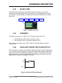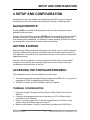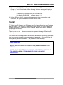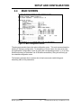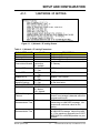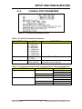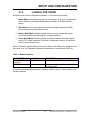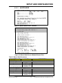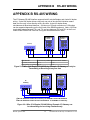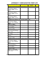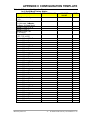
1
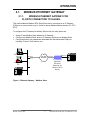
BENTEK SYSTEMS LTD
SCADA and Telemetry Solutions
SCADALink IP Gateway
Modbus Ethernet Gateway/Terminal Server
User Manual
IP Gateway Ver 1.00
Last Revised Dec.18, 2002
BENTEK SYSTEMS LTD
504 - 42 Ave S.E. Calgary, Alberta, Canada T2G 1Y6 Ph: (403) 243-5135 Fax: (403) 243-5165
email: [email protected]
web: www.scadalink.com
Bentek Systems Ltd.
0
SCADALink IP Gateway User Manual V 1.00
CONTENTS
1
INTRODUCTION............................................................................................................... 3
2
OPERATION ..................................................................................................................... 4
2.1. MODBUS ETHERNET GATEWAY ........................................................................................................ 5
2.1.1.
MODBUS ETHERNET GATEWAY FOR PLC/RTU CONNECTION TO SLAVES. ........................... 5
2.1.2.
MODBUS ETHERNET GATEWAY FOR SCADA HOST OR PLC/RTU AS A SERIAL MASTER ..... 6
2.2. MODBUS MULTIPLEXER ...................................................................................................................... 7
2.3. VIRTUAL SERIAL PORT ........................................................................................................................ 8
3
HARDWARE DESCRIPTION .......................................................................................... 10
3.1.
LEDS ........................................................................................................................................................ 10
MEMBRANE LED’s..................................................................................................................................................10
CONNECTOR LED’s ................................................................................................................................................11
3.2. CONNECTORS ....................................................................................................................................... 11
3.2.1.
POWER ............................................................................................................................................ 11
3.2.2.
EARTH GROUND............................................................................................................................ 12
3.2.3.
SERIAL PORT .................................................................................................................................. 12
3.2.4.
RS-485 COM1 .................................................................................................................................. 13
3.2.5.
ETHERNET ...................................................................................................................................... 13
3.2.6.
AUXILLARY DIGITAL INPUT AND OUTPUT ............................................................................... 13
4
SETUP AND CONFIGURATION ..................................................................................... 14
NAVIGATION KEYS ......................................................................................................................................... 14
GETTING STARTED.......................................................................................................................................... 14
ACCESSING THE CONFIGURATION MENU................................................................................................. 14
TERMINAL CONFIGURATION ...................................................................................................................... 14
TELNET ........................................................................................................................................................... 15
4.4
MAIN SCREEN....................................................................................................................................... 16
4.1.1.
1) NETWORK / IP SETTING ........................................................................................................... 17
4.1.2.
2) SERIAL PORT PARAMETERS .................................................................................................... 18
4.1.3.
3) SERIAL PORT MODE ................................................................................................................. 19
4.3.3.1.
4.3.3.2.
4.3.3.3.
4.3.3.4.
4.1.4.
5
4) MISCELLANEOUS ...................................................................................................................... 24
TROUBLESHOOTING TIPS............................................................................................ 25
5.1.
5.2.
5.3.
5.4.
5.5.
5.6.
5.7.
5.8.
5.9.
5.10.
6
MASTER MODE......................................................................................................................................20
SLAVE MODE.........................................................................................................................................21
MODBUS MUX MODE...........................................................................................................................22
VIRTUAL SERIAL MODE......................................................................................................................23
PROBLEM: UNABLE TO PING UNIT ............................................................................................................. 25
PROBLEM: UNIT DOES NOT RESPOND TO POLL........................................................................................... 25
PROBLEM: I AM ABLE TO POLL BUT CONNECTION KEEPS DROPPING .......................................................... 25
PROBLEM: I COULD NOT GET MORE THAN 3 CONNECTIONS TO IP GATEWAY ............................................ 25
PROBLEM: CONNECTION TAKES LONG TIME TO ESTABLISHED ................................................................... 25
PROBLEM: I AM NOT GETTING 100% COMMUNICATIONS ......................................................................... 26
PROBLEM: I COULD NOT GET IN TELNET CONFIGURATION ......................................................................... 26
PROBLEM: TELNET MENU CRASHES .......................................................................................................... 26
PROBLEM: I HAVE A MULTIPLE IP GATEWAYS AND I DON’T KNOW WHICH IS WHICH ............................... 26
PROBLEM: IP GATEWAY CRASHES IF I ENABLED EVERYTHING ................................................................. 26
INSTALLATION............................................................................................................... 27
6.1. PHYSICAL MOUNTING........................................................................................................................ 27
6.2. BENCH SETUP AND TEST ................................................................................................................... 29
6.2.1.
EQUIPMENT ................................................................................................................................... 29
6.2.2.
USER CONFIGURATION ............................................................................................................... 29
7
TECHNICAL SPECIFICATIONS...................................................................................... 30
Bentek Systems Ltd.
1
SCADALink IP Gateway User Manual V 1.00
APPENDIX A UPGRADING FIRMWARE.............................................................................. 31
APPENDIX B RS-485 WIRING .............................................................................................. 32
APPENDIX C CONFIGURATION TEMPLATE....................................................................... 33
WARRANTY .......................................................................................................................... 38
Bentek Systems Ltd.
2
SCADALink IP Gateway User Manual V 1.00
INTRODUCTION
1 INTRODUCTION
The SCADALink IP Gateway is a Multi Serial Port Server / Ethernet Gateway designed
for industrial applications. Equipped with 3 Serial Ports and a single 10BaseT Ethernet
Port, it can be configured to perform one or more of the following functions:
1. Modbus Ethernet Gateway (Modbus TCP, TCP or UDP):
•
•
Serial Connection to Modbus RTU Slave
Serial Connection to Modbus Master (IP Lookup, Modbus Address to
IP Lookup)
2. Virtual Serial Port :
•
•
Serial Port Server
Serial Port Client
3. Modbus Port Multiplexer
Bentek Systems Ltd.
3
SCADALink IP Gateway User Manual V 1.00
OPERATION
2 OPERATION
Equipped with 3 Serial Ports and 1 10BaseT Ethernet Port, the IP Gateway allows TCP
and Legacy Serial Devices to interoperate with each other. It can be configured to
perform one or more of the following functions:
4. Modbus Ethernet Gateway (Modbus TCP, TCP or UDP):
•
•
Serial Connection to Modbus RTU Slave
Serial Connection to Modbus Master (IP Lookup, Modbus Address to
IP Lookup)
5. Virtual Serial Port :
•
•
Serial Port Server
Serial Port Client
6. Modbus Port Multiplexer
The difference between Virtual Serial Port and a Modbus Port is that a Virtual serial port
is a dedicated point to point, protocol independent serial link whereas the Modbus serial
mode incorporates a Modbus Gateway functionality that allow multiple simultaneous
host connections:
1. Modbus Ethernet Gateway:
•
•
•
Ethernet to Serial Connection to Modbus RTU Slave
Ethernet to Serial Connection to Modbus Master (Modbus Address to IP Lookup)
Serial to Ethernet Connection to IP Enabled Modbus Slave
2. “Virtual” Serial Port End-to-End Serial emulation over Ethernet connection:
Table 1: Available Serial Port Options
CONFIGURABLE OPTIONS FOR COM1, 2
and 3
VIRTUAL PORT OPTION
MODBUS PORT OPTION:Modbus TCP
MODBUS PORT OPTION:Modbus over TCP
MODBUS PORT OPTION:Modbus over UDP
In Modbus Ethernet Gateway mode, the IP Gateway translates Modbus-RTU protocol to
Modbus TCP, TCP or UDP protocol to enable a Modbus Slave/Master device connected
to the IP Gateway’s COM port to communicate over the network to a remote Ethernet
device.
In Virtual Serial mode, a pair of IP Gateways enables 2 Serial devices to establish Endto-End Serial communication over the network.
Bentek Systems Ltd.
4
SCADALink IP Gateway User Manual V 1.00
OPERATION
2.1.
MODBUS ETHERNET GATEWAY
2.1.1.
MODBUS ETHERNET GATEWAY FOR
PLC/RTU CONNECTION TO SLAVES.
This mode enables a Modbus-RTU Serial Slave device connected to an IP Gateway
COM port to communicate to up to 3 local or remote Modbus Master devices (PC, PLC,
RTU).
To configure the IP Gateway for Modbus Slave mode, the main points are:
•
•
•
Assign IP and Modbus Slave address to IP Gateway
Configure the Modbus Slave device’s IP Gateway Serial port as Modbus Slave
Configure all other port parameters associated with that associated COM port
including: Protocol, Port Address, etc…
SCADA Host
Ethernet
LAN, WAN,
INTERNET
Ethernet
IP Gateway
(Modbus
Ethernet
Gateway for
Modbus RTU
Slave)
Configuation
PC
RS-232
COM
PLC, RTU
PLC, RTU
Figure 1: Ethernet Gateway – Modbus Slave
Bentek Systems Ltd.
5
SCADALink IP Gateway User Manual V 1.00
OPERATION
2.1.2.
MODBUS ETHERNET GATEWAY FOR
SCADA HOST OR PLC/RTU AS A SERIAL MASTER
This configuration enables a Serial Master (Modbus-RTU) connected to an IP Gateway
COM port to communicate to remote Serial (Modbus-RTU) and Ethernet (Modbus TCP
or Modbus over TCP) Slaves. The Modbus-RTU Master can address up to 50 devices.
To configure the IP Gateway for Modbus Master mode, the main points are:
•
•
•
Configure the Modbus Master IP Gateway COM port to be Modbus Gateway Master
Configure all other Modbus Master Gateway parameters associated with that COM
port including: Destination IP address, Port Address, Protocols, etc…
If a Slave site has a Serial Slave, configure the IP Gateway COM port for Modbus
Slave mode; Ethernet Slave devices connect via internet or local LAN.
Ethernet
Modbus
TCP
PORT
Ethernet 502
IP 10.0.1.1
PLC, RTU
Modbus
Modbus
Slave
Ethernet
RS-232
COM1
Modbus
IP Gateway
Serial
(Modbus Ethernet
Master Gateway for Modbus
Serial Master)
MODBUS ADD.
1
2
3
IP ADD.
10.0.1.1
10.0.1.2
10.0.1.3
LAN, WAN,
INTERNET
TCP
PORT
IP 10.0.1..2 502
COM1
RS-232
IP Gateway
PLC, RTU
(Modbus Ethernet
Modbus
Gateway for
Slave
Modbus Slave) TCP
PROTOCOL
MODBUS TCP
MODBUS TCP
MODBUS OVER TCP
PORT
502
502
500
PORT
IP 10.0.1.3 500
COM1
IP 10.0.1.3
RS-232
IP Gateway
(Modbus Ethernet
Gateway for
Modbus Slave)
PLC, RTU
Modbus
Slave
Figure 2: Ethernet Gateway – Modbus Master
Bentek Systems Ltd.
6
SCADALink IP Gateway User Manual V 1.00
OPERATION
2.2.
MODBUS MULTIPLEXER
This configuration allows all 3 COM ports of the IP Gateway to be used as a local
Modbus Serial Multiplexer. 2 locally connected Modbus-RTU Master devices and
multiple remote Ethernet Masters can simultaneously communicate to 1 locally
connected Modbus-RTU Slave device.
Modbus
Master
LAN, WAN,
INTERNET
Ethernet
IP Gateway
(Modbus
Multiplexer)
RS-232
COM1
Configuration
PC
RS-232
RS-232
COM2
COM3
Modbus
Serial
Master
PLC, RTU
Modbus
Slave
PLC, RTU
Modbus
Master
Figure 3: MULTIPLEXER
Bentek Systems Ltd.
7
SCADALink IP Gateway User Manual V 1.00
OPERATION
2.3.
VIRTUAL SERIAL PORT
This mode emulates Serial communication over an Ethernet or Internet network. It
enables communications between Serial devices over a TCP/IP, LAN, WAN or Internet
as if they were connected by a point to point Serial link.
In Virtual Serial mode, there must be at least one IP Gateway Server and one IP
Gateway Client. A Server passively listens for requests for establishment of a
connection, whereas the Client initiates requests for and establishes a connection to the
Server.
Each Client can only connect to one Server; a Client’s Destination IP address and
Destination Port parameters completely specify this one Server. When RS232 data is
detected on the Client IP Gateway’s COM port, the Client IP Gateway attempts to
establish a data link to the remote Server. If the Server is free, it receives the Clients
request and establishes a bi-directional link with the Client. After a link has been
established, the Server will only communicate with that Client until the session is finished
or dropped due to timeout.
The Serial Port Client can be:
•
•
•
•
Another IP Gateway
Host application software
COM Port Redirector software
Serial Port Server.
To configure the IP Gateway for Virtual Serial mode, the main points are:
•
•
•
•
•
At least one IP Gateway must be configured as a Client and one as a Server
Each Client can only be programmed to communicate with only one Server
The Client’s Destination IP address and Port number parameters specify the Server
Set the Virtual-Serial No Message Timeout parameter in both the Server and Client
to guarantee the session will close down and not hang due to an unexpected
interruption.
There can be multiple Servers and each can establish links with multiple Clients but
only one at a time. The session must end before another Client has access to that
Server.
Bentek Systems Ltd.
8
SCADALink IP Gateway User Manual V 1.00
OPERATION
RS-232
A.
Ethernet
COM
PC
LAN, WAN,
INTERNET
COM
IP Gateway
(Server)
IP Gateway
(Client)
Ethernet
B.
LAN, WAN,
INTERNET
COM
IP Gateway
(Server)
Ethernet
COM Port
Redirection
Software
PC
LAN, WAN,
INTERNET
COM
Ethernet
PLC, RTU
RS-232
Ethernet
COM
3rd Party
Serial Port
Server in "Client"
mode
RS-232
D.
PLC, RTU
RS-232
Ethernet
Host Application
running TCP/IP
Port Client
C.
RS-232
Ethernet
IP Gateway
(Server)
LAN, WAN,
INTERNET
PLC, RTU
RS-232
Ethernet
COM
IP Gateway
(Server)
PLC, RTU
Figure 4: Virtual Serial Port Configurations
Bentek Systems Ltd.
9
SCADALink IP Gateway User Manual V 1.00
HARDWARE DESCRIPTION
3 HARDWARE DESCRIPTION
The IP Gateway is housed in a 7.5” x 5.75” x 2.875” panel mount aluminum enclosure.
The top face of the enclosure houses status LEDs and the back face of the enclosure
houses Power, Serial, and Ethernet Connectors.
3.1.
LEDs
3. COM3 TX, RX
2. AUXILLARY
DIN DOUT LED
DIN IS NOT USED
4. COM1 TX, RX
5. COM2 TX, RX
6. Ethernet
1. Status LED
UNUSED
7. Virtual
Serial Port
Indicator
Figure 5: Front Panel LED Display
Table 2: LED Function Chart
ITEM No.
LED NAME
1
2
STATUS
DIN, DOUT
3
COM3 TX, RX
4
COM1 TX, RX
5
COM2 TX, RX
6
ETHERNET
7
SPARE1,2,3,4
Bentek Systems Ltd.
DESCRIPTION
MEMBRANE LED’s
STATUS=ON indicates power
DOUT = ON when DOUT is logic Hi
DIN IS NOT USED
TX = ON: data From IP Gateway To COM3 device
RX = ON: data To IP Gateway From COM3 device
TX = ON: data From IP Gateway To COM1 device
RX = ON: data To IP Gateway From COM1 device
TX = ON: data From IP Gateway To COM2 device
RX = ON: data To IP Gateway From COM2 device
ETHERNET= ON indicates that the IP Gateway is
configured to listen on a TCP socket and is
mapped to a serial port
1,2,3 are on when COM1, 2 or 3 is respectively
configured as a Virtual Serial port.
NOTE: ONLY ONE OF 1,2 OR 3 CAN BE ON AT
10
SCADALink IP Gateway User Manual V 1.00
HARDWARE DESCRIPTION
7
8
ETHERNET – RJ45
ETHERNET – RJ45
3.2.
ANY ONE TIME.
LED 4 IS NOT USED.
CONNECTOR LED’s
GREEN = ON indicates Ethernet data (See Fig.1)
YELLOW = ON indicates link (See Fig.1)
CONNECTORS
The Figure below shows the connectors of the IP Gateway.
COM1 (User Port)
RS-232 DB9F DCE
COM1 (User Port)
RS-485 (full or half-duplex)
5 pin Terminal Block
COM3 (Config Port)
RS-232 RJ11-6
Input Power: 930VDC and
Earth GND
3 pin Terminal
Block
Ethernet RJ-45
10BaseT Port with
integrated LEDs
Auxiliary
Digital I/O
2 pin Terminal
Block (DIN IS
UNUSED)
COM2 (Expansion)
Port RS-232 DB9F
Figure 6: IP Gateway Connectors
3.2.1.
POWER
The IP Gateway requires a DC power supply of 9-30VDC. At 24 V, the IP Gateway
draws a nominal 50mA. Power is connected to the IP Gateway via the removable 3 pin
Power Terminal Block. Maximum wire size is 16AWG.
+ (9-30VDC)
DIGITAL O/P.
- (9-30VDC)
DIGITAL I/P
(NOT USED)
EARTH GND.
Figure 7: Power and Auxillary I/O Connector
Bentek Systems Ltd.
11
SCADALink IP Gateway User Manual V 1.00
HARDWARE DESCRIPTION
3.2.2.
EARTH GROUND
NOTE: IF TRANSIENT PROTECTION IS REQUIRED, IT IS IMPORTANT TO
CONNECT A PROPERLY GROUNDED 16AWG EARTH GROUND WIRE TO THE
“EARTH GND” TERMINAL ON THE REMOVABLE 3 PIN TERMINAL BLOCK. SEE
ABOVE FIGURE. DO NOT CONNECT EARTH GROUND AND POWER SUPPLY
GROUND TOGETHER.
3.2.3.
SERIAL PORT
There are 3 Serial ports available on the IP Gateway. All 3 are configurable using the IP
Gateway Configuration software.
COM1 and COM2 are wired as 5 pin DCE devices and require:
•
•
Straight-through cable to connect to a PC (or other DTE device)
Null modem cable to connect to a modem (or other DCE device)
COM1 and COM2 pin assignments are:
•
•
•
•
•
Pin.2 RXD
Pin.3 TXD
Pin.5 GND
Pin.7 RTS (future)
Pin.8 CTS (future)
COM3 is an RJ-11 connector, which is normally a factory port only. However, by
ordering a custom cable, this port is also available to the user for the functions shown
below:
Table 3: COM3 FUNCTION vs. CABLE
COM3 FUNCTION
3 Wire DCE Serial Port
Field FLASH Upgrade
Port
CUSTOM CABLE PART NO.
SCADALink P/N CBL-USR-01
SCADALink P/N CBL-PRG-01
CABLE FUNCTION
Convert RJ11 to DB9F
See Appendix A
NOTE: COM1 – RS232 IS INTERNALLY WIRE-ORED WITH THE COM1: RS-485
PORT. BOTH PORTS CAN BE USED SIMULTANEOUSLY IF THE DEVICES
CONNECTED TO THE PORTS ARE BOTH MODBUS SLAVES. DO NOT CONNECT
AND USE 2 MASTER DEVICES OR DATA CONTENTION MAY OCCUR.
Bentek Systems Ltd.
12
SCADALink IP Gateway User Manual V 1.00
HARDWARE DESCRIPTION
3.2.4.
RS-485 COM1
The RS-485 can be either 2-wire half duplex or 4-wire full duplex. Up to 128 IP
Gateway’s can be multi-dropped onto one RS-485 bus. See Appendix B for RS-485
wiring details. The RS-485 port is internally Wire-Ored with the RS-232 port. See the
above note.
TX +
TX -
RX +
RX -
GND.
Figure 8: RS-485 Connector
3.2.5.
ETHERNET
This Ethernet connector is a 10Base-T RJ-45 connector wired as a DTE:
•
•
Use Straight-thru CAT5 cable to connect to a Hub
Use Crossover CAT5 to connect to computer or PLC.
This connector has integral status LEDs: Green LED indicates data while Yellow
indicates Link.
3.2.6.
AUXILLARY DIGITAL INPUT AND OUTPUT
See Fig.7 above for a picture of the Auxillary digital input/output connector. Digital input
is not available on the IP Gateway. The user can force this open collector digital output
high or low from within the UNICON configuration software 4) Miscellanous menu for
diagnostic purposes. The Figure below shows typical wiring of a relay coil from a 24V
power source. The power can between 9 and 30V.
DO
-
R
+
24V
Figure 9: Auxillary DO Wiring Example
Bentek Systems Ltd.
13
SCADALink IP Gateway User Manual V 1.00
SETUP AND CONFIGURATION
4 SETUP AND CONFIGURATION
Configuration is done via software, which operates as an ASCII terminal: there are
Selection Prompts to select options and Parameter Prompts for entering values.
NAVIGATION KEYS
Pressing <ESC> from either Prompt jumps the user out of the existing menu and
displays the previous menu.
During a Parameter Prompt, pressing <ENTER> will accept the default value indicated in
brackets and move the Prompt to the next parameter. If an invalid entry is made, an
error message will be displayed. If a valid entry is made, pressing <ENTER> will accept
the entered value and move the Prompt to the next parameter.
GETTING STARTED
Before entering detailed setup and configuration information, the user should review the
Operation section of this manual to see which modes and functions are best suited for
their application. Once that is done, follow the instructions in this section to configure the
appropriate settings.
After the units are configured, it is strongly advised to bench test the system before
installing it out in the field; an incorrectly configured unit is a lot easier to test and
troubleshoot on the bench than in the field.
ACCESSING THE CONFIGURATION MENU
The configuration menu can be accessed in one of two ways:
1. Terminal Program such as HyperTerminal (configured for 9600 N 8 1) running on PC
connected to COM1 via straight-through Serial Cable
2. TELNET Connection to the IP Gateway’s internal IP address.
TERMINAL CONFIGURATION
1. Connect a Straight-Through 9-pin Serial cable to COM1 RS232 Port on the IP
Gateway.
2. Close any existing applications that may be using your PC’s COM port that is
connected to the IP Gateway.
3. Open a Terminal program such as Windows HyperTerminal, ProComm or any
another Terminal emulation program on the PC.
4. Make sure the program is setup to communicate at a baud rate of 9600 8-N-1.
Bentek Systems Ltd.
14
SCADALink IP Gateway User Manual V 1.00
SETUP AND CONFIGURATION
5. Make sure a 9-30VDC Power Supply is connected to the IP Gateway and turn the
Power on. The LED’s will flash and the following Welcome message will display on
the Terminal:
SCADALINK IP Gateway, BENTEK SYSTEMS Ltd.
Unit Number BA02I00001 Software version 1.01
6. Hit the ESC key within 5 seconds of this message to enter Configuration mode.
Otherwise, the system will default to normal runtime mode.
TELNET
To Telnet to an IP Gateway, the IP Gateway must first be configured with an IP address
and Port number. This is done in 1) Network/IP Setting menu. To Telnet to a target IP
Gateway connected to a network, while in Windows, open a DOS window. At the DOS
prompt, type the following:
Telnet xxx.xxx.xxx.xxx
address)
(where xxx.xxx.xxx.xxx represents the target IP Gateway IP
You will then see a message stating the Site name and a prompt requesting a password:
type in the correct password. (your own configured password, or, if the unit is new, the
factory default password: “scadalink”. The password is case sensitive).
NOTE1: THE TELNET DEFAULT PASSWORD IS “scadalink” AND IS
CASE-SENSITIVE
NOTE2: USER PASSWORD IS ASSIGNED IN 4) MISCELLANOUS. IN THIS
SECTION.
NOTE3: IF YOU FORGET YOUR PASSWORD, USE TERMINAL MODE TO GO
TO 4) MISCELLANOUS. TERMINAL MODE HAS NO PASSWORD
PROTECTION.
Bentek Systems Ltd.
15
SCADALink IP Gateway User Manual V 1.00
SETUP AND CONFIGURATION
4.4
MAIN SCREEN
Figure 10: Main Configuration Screen
The above screenshot shows the main configuration menu. This main screen shows the
existing IP Gateway configuration. To change any of these values, the user must enter
the appropriate Configuration screen by typing the corresponding number (1 to 4) at the
Selection prompt (on the bottom line of the above screenshot). Doing this will bring up
the selected configuration menu.
The following sections show a screen shot of each menu and a table listing and
describing each of the parameters.
Bentek Systems Ltd.
16
SCADALink IP Gateway User Manual V 1.00
SETUP AND CONFIGURATION
4.1.1.
1) NETWORK / IP SETTING
Figure 11: 1) Network / IP setting Screen
Table 4: 1) Network / IP setting Parameters
PARAMETER NAME
IP Address
Gateway Address
Netmask
Number of
Connections Allowed
VALUE
xxx.xxx.xxx.xxx
xxx.xxx.xxx.xxx
xxx.xxx.xxx.xxx
1 = one
connection
2 = multiple
Enable UDP
0 = No
1 = Yes
Enable TCP
0 = No
1 = Yes
Enable MTCP
0 = No
1 = Yes
0 = No
Change Advanced
Network Settings
1 = Yes
ADVANCED NETWORK SETTINGS
Network Latency
0 – 10
0 = fastest
10 = slowest
TCP No Message
2 – 1800 sec.
Timeout
Minimum
Retransmission Time
250 ms. min.
Maximum
Retransmission Time
50,000 ms. max.
Bentek Systems Ltd.
DESCRIPTION
IP Gateway IP address
IP Gateway Gateway address
IP Gateway Netmask
Number of Masters that can connect to the
IP Gateway.
UDP Protocol
TCP Protocol
Modbus TCP Protocol
1 = yes allows user to edit the parameters
on the lines below
Time in seconds that the connection will be
closed if no message is detected within this
programmed timeout
Minimum timeout in ms before retransmitting an UNACKED message. We
recommend a minimum value for this
setting.
Maximum timeout in ms to re-transmitting
an UNACKED message. Adjust this value
to 1.5 the maximum response-time if LOST
MESSAGES is a KNOWN problem on your
network.
17
SCADALink IP Gateway User Manual V 1.00
SETUP AND CONFIGURATION
4.1.2.
2) SERIAL PORT PARAMETERS
Figure 12: 2) Serial Port Parameters Screen
Table 5: 2) Serial Port Parameters Parameters
PARAMETER NAME
Baud Rate
Data mode
Message Timeout
VALUE
1 = 1200 baud
2 = 2400 baud
3 = 4800 baud
4 = 9600 baud
5 = 19200 baud
6 = 38400 baud
7 = 57600 baud
8 = 115200 baud
1 = RTU
2 = ASCII
100 to 30,000 ms
10ms resolution
DESCRIPTION
Asychronous Serial port baud rate
Modbus RTU or ASCII
Maximum allowable time for serially
connected device to response
Table 6: 2) Serial Port Parameters Data Format Parameters: Allowed Combinations
DATA BITS
7
PARITY
0 = none
8
1 = odd
2 = even
0 = none
1 = odd
2 = even
Bentek Systems Ltd.
18
STOP BITS
1
2
1
1
1
2
1
1
SCADALink IP Gateway User Manual V 1.00
SETUP AND CONFIGURATION
4.1.3.
3) SERIAL PORT MODE
Each Serial Port can be configured to operate in 1 of the following 4 modes:
1. Master Mode: Each Master can poll 1 or more slaves. There are 2 configuration
menus: Master for a Single Remote Slave and Master for Multiple Remote
Slaves.
2. Slave Mode: One or more masters can poll the serially connected (SLAVE)
device through the configured protocol(s)
3. Modbus MUX Mode: Multiple Masters (local or remote) can poll the serially
connected (SLAVE) device through the configured protocol.
4. Virtual Serial Mode: Simulate a serial connection between two serial devices
using a TCP virtual connection. There are 2 configuration menus: Virtual Serial
Client or Virtual Serial Server.
When 3) Serial Port Mode Setting menu item is chosen, the COM port to configure must
be chosen first. The Table below shows the parameters for selecting the COM port.
Table 7: Mode Parameters
PARAMETER NAME
Choose COM port to
configure
COM X Mode
VALUE
1-3
DESCRIPTION
1-3 for COM1 to COM3 respectively
0-3
0 = Not used, 1=Master, 2=Slave, 3=Mux,
4=Virtual Serial
An example screenshot and parameter description table is given for each of these in the
following sections.
Bentek Systems Ltd.
19
SCADALink IP Gateway User Manual V 1.00
SETUP AND CONFIGURATION
4.3.3.1.
MASTER MODE
Figure 13: Master Mode Screen: 1 Remote
Figure 14: Master Mode Screen: Multiple Remote Sites
Table 8: Master Mode Parameters
PARAMETER NAME
1 REMOTE
Destination IP
Destination Port
Select Protocol
2 MULTIPLE REMOTES
Destination RTU ID
Destination IP
Destination Port
Select Protocol
Bentek Systems Ltd.
VALUE
DESCRIPTION
xxx.xxx.xxx.xxx
2 to 65535
1 = UDP, 2= TCP
3 = Modbus TCP
IP address in dotted decimal notation
Port Number
Protocol
1-255
xxx.xxx.xxx.xxx
2 to 65535
1 = UDP,2 = TCP
3 = Modbus TCP
Modbus Address
IP address in dotted decimal notation
Port Number
Protocol
20
SCADALink IP Gateway User Manual V 1.00
SETUP AND CONFIGURATION
4.3.3.2.
SLAVE MODE
Each IP Gateway can support a maximum of 3 Slave connections. These connections
can exist on just one physical COM port up to all 3 physical COM ports. Each connection
can also be configured for Modbus TCP, TCP or UDP.
NOTE: MODBUS TCP, TCP AND UDP PROTOCOLS ARE ENABLED/DISABLED
IN THE 1) NETWORK /IP CONFIGURATION MENU AND NOT THIS ONE.
The example below shows COM1 configured as a Master, COM3 unconfigured and
COM2 being configured as a Slave. In this example, only Modbus TCP has been
enabled. TCP and UDP have been disabled in the Network/IP Configuration menu. The
user is prompted to enter a port number only for the Modbus TCP port.
Figure 15: Slave Mode Screen
Table 9: Slave Mode PARAMETERS
PARAMETER NAME
MTCP Port
TCP Port
UDP Port
VALUE
2 to 65535
2 to 65535
2 to 65535
DESCRIPTION
Modbus TCP Protocol
TCP Protocol
UDP Protocol
NOTE: IN THE ABOVE TABLE, ONLY THOSE PROTOCOLS WHICH ARE
ENABLED IN 1) NETWORK /IP CONFIGURATION MENU CAN BE EDITED.
Bentek Systems Ltd.
21
SCADALink IP Gateway User Manual V 1.00
SETUP AND CONFIGURATION
4.3.3.3.
MODBUS MUX MODE
Modbus Multiplexer mode can be used to allow up to 2 Modbus MASTERs connected to
2 IP Gateway COM ports to simultaneously poll the same Modbus SLAVE connected to
the 3rd IP Gateway COM port.
By using a combination of SLAVE and MUX configuration, both locally connected Serial
Modbus MASTER AND remotely-connected TCP/IP Modbus MASTERS can
simultaneously poll the same Modbus SLAVE.
Do the following in the MUX menu to multiplex a COM port to another COM port:
1. Select the COM port which the Modbus RTU will SLAVE connect to.
2. Select the COM port which the Modbus RTU MASTER will connect to.
NOTE: MODBUS TCP, TCP AND UDP PROTOCOLS MUST BE
ENABLED/DISABLED IN THE 1) NETWORK /IP CONFIGURATION MENU
FIRST BEFORE ANY OF THE SETTINGS HERE WILL BE READ.
In the example below, COM3 is first chosen as the COM port which the Modbus RTU
MASTER will connect to. The user is then prompted for the COM port which the Modbus
RTU SLAVE will connect to. COM2 is specified.
Also notice in the example that COM2 is already configured as a Modbus SLAVE able to
receive Modbus TCP messages on port 502. This combination of SLAVE and MUX
configuration allows a remote Modbus TCP MASTER and a local Modbus RTU
MASTER connected to COM3 to simultaneously poll the Modbus SLAVE connected to
COM2.
Figure 16: Mux Mode Screen
Table 10: Mux Mode Parameters
PARAMETER NAME
SLAVE COM Port to
MUX to
Bentek Systems Ltd.
VALUE
1, 2 or 3
DESCRIPTION
Serial Port that is assigned to be a
Multiplexed Modbus Slave.
22
SCADALink IP Gateway User Manual V 1.00
SETUP AND CONFIGURATION
4.3.3.4.
VIRTUAL SERIAL MODE
Figure 17: Virtual Serial Mode Screen: Server
Figure 18: Virtual Serial Mode Screen: Client
Table 11: Virtual Serial Mode Parameters
PARAMETER NAME
Virtual Serial Port
Client or Server
SERVER
TCP Port to Listen on
No-message Timeout
CLIENT
Enabled Client
“Connected” Message
Destination IP
Destination Port
No-message Timeout
Bentek Systems Ltd.
VALUE
0 = Server
1 = Client
DESCRIPTION
Client: devices requesting service
Server: devices responding to requests
2 to 65535
2 to 1800 sec.
Time to wait before closing connection if no
activity (only applies to Virtual Serial)
0 = No
1 = Yes
xxx.xxx.xxx.xxx
2 to 65535
2 to 1800 sec.
Connected to “Virtual Serial Server IP” Port
“number”
IP address in dotted decimal notation
Time to wait before closing connection if no
activity (only applies to Virtual Serial)
23
SCADALink IP Gateway User Manual V 1.00
SETUP AND CONFIGURATION
4.1.4.
4) MISCELLANEOUS
Figure 19 4) Miscellaneous Mode Screen
Table 12: 4) Miscellaneous Mode Parameters
PARAMETER NAME
VALUE
DESCRIPTION
1 DIGITAL OUTPUT CONTROL
Set logic level for Auxillary digital output.
Enter Output Level
0 = low logic
1 = high logic
2 SITE INFO
Site Info
40 characters
Description of Site IP Gateway is installed
maximum
at.
3 CHANGE TELNET CONFIGURATION PASSWORD
Change Telnet
4 to 10 characters Default is “scadalink” This password is
Configuration
alphanumeric
case-sensitive.
Password
Bentek Systems Ltd.
24
SCADALink IP Gateway User Manual V 1.00
INSTALLATION
5 TROUBLESHOOTING TIPS
5.1.
Problem: Unable to ping unit
Solution:
-Check network/ip setting for correct IP address, gateway, netmasks
-Check ethernet cable connection: RJ45 straight through cable is required
5.2.
Problem: Unit does not respond to poll
Solution:
-Configure serial port mode settings
-Ensure the SLAVE device is connected to the configured serial port
-Ensure correct serial setting such as: BAUD, FORMAT, and TIMEOUT
-Ensure matching RTU address
-Check for Master timeout. If the master is polling too quickly the slave may not
have enough time to respond.
-Check for Slave timeout, the slave must be able to response within the time
specified on the serial port (Serial setting: baud, format, and timeout)
-Make sure the serially connected SLAVE is set up correctly
5.3.
Problem: I am able to poll but connection keeps
dropping
Solution:
-Check for Master timeout, the master could be timing out too quick
-Check Advanced Network Setting for “TCP No Message Timeout”. IP gateway
will close the connection if no message is detected within this timeout. For
example: the “TCP No Message Timeout” is set to 2 seconds, the master is
polling at every 4 seconds. The IP gateway is closing the connection after 2
seconds causing the connection to drop.
5.4.
Problem: I could not get more than 3 connections to
IP gateway
Solution:
- IP Gateway can only handle 3 masters simultaneously.
5.5.
Problem: Connection takes long time to established
Solution:
-Disable not-used protocol
-Reset COM port setting to “Not-Used” for not-used ports
-Set Number of Connections to 1 if only one is required
-If more than 1 protocol is enabled, increase network latency in advanced setting,
Bentek Systems Ltd.
25
SCADALink IP Gateway User Manual V 1.00
INSTALLATION
this determines how long the IP gateway will spin on each protocol while waiting
for a connection.
-Over a WAN, increasing network latency will help the connection to establish
quicker
5.6.
Problem: I am not getting 100% Communications
Solution:
-Increase number of retry on master
-Over a WAN, or over RADIO where lost messages occurs, set the Maximum
Retransmission Timeout to 1.5times the maximum response time
-If multiplexing to one slave device, ensure the masters have reasonable poll
delay
5.7.
Problem: I could not get in telnet configuration
Solution:
-Make sure you enter the correct password. The password could be change in
terminal menu and telnet menu
-Reboot IP gateway if you could not get to the unit at all
-Only 1 telnet menu is available
5.8.
Problem: Telnet menu crashes
Solution:
-IP gateway is too busy handling other connections, turn the polling off while
telnet
-Telnet menu automatically timeouts if menu is not active in approximately 1
minute
5.9.
Problem: I have a Multiple IP Gateways and I don’t
know which is which
Solution:
-Give each unit a description, this description is part of the telnet password
prompt
5.10.
Problem: IP Gateway crashes if I enabled everything
Solution:
-Only enabled setting that is required, overloading cause crashes
-Settings that are enabled but not in use takes up resources too
Bentek Systems Ltd.
26
SCADALink IP Gateway User Manual V 1.00
INSTALLATION
6 INSTALLATION
Installation consists of 3 aspects:
1. Physical mounting
2. Basic bench setup and testing
6.1.
PHYSICAL MOUNTING
The IP Gateway is a panel mount device usually mounted on a backpanel by using 4 #
screws through the 4 keyslot holes on the IP Gateway mounting bracket.
The Figure below shows the IP Gateway’s physical dimensions.
Bentek Systems Ltd.
27
SCADALink IP Gateway User Manual V 1.00
INSTALLATION
7 13/16"
5/16"
5/8"
6 9/16"
5/8"
7/8"
2 7/16"
4 15/16"
1 1/2"
FRONT VIEW
2 7/8" 2 3/4"
1/8"
SIDE VIEW
Figure 20: Physical Dimensions
Bentek Systems Ltd.
28
SCADALink IP Gateway User Manual V 1.00
INSTALLATION
6.2.
BENCH SETUP AND TEST
It is recommended to bench test communications before attempting field installation.
This is especially advised for new User’s of the equipment. Any problems due either to
misconfiguration or equipment fault will be much easier to identify and fix when all the
equipment is accessible from the bench.
6.2.1.
EQUIPMENT
For the following bench setup and preliminary testing, have the following equipment
available:
1. IP Gateway units to be installed
2. Devices which will be connected to IP Gateway in the field or devices that can
emulate the field device’s interface
3. Configuration PC
4. 9-26VDC regulated power supply
5. All necessary cables
6. IP Gateway Programming cable
7. User manual
8. List of configuration parameters and their values prepared as per following section.
6.2.2.
USER CONFIGURATION
Before bench testing and preliminary setup, read the User manual and look at the
various functions to determine which one is most applicable to your application. Make a
copy of the Configuration Parameter Template found in Appendix C and write down all
your configuration parameters.
Bentek Systems Ltd.
29
SCADALink IP Gateway User Manual V 1.00
TECHNICAL SPECIFICATIONS
7 TECHNICAL SPECIFICATIONS
GENERAL
Power
Input Voltage
Current
(Average)
Temperature Range
Size: Max
dimensions
Operating
Length
Width
Height
Mounting
Weight
9-30 VDC
50mA @24 V
(assumes Continuous operation in MASTER
mode)
-40 to 85 Deg. C
7.5”
5.75” (including Top Faceplate connectors)
2.875”
4 x 5/32’’ Dia. mounting holes (Fits #8
Screws), 2.400’’ vertical 6.218’’ horizontal
850 grams
SERIAL COMMUNICATIONS
Interface
Data Rates
Data Format
Flow Control
Protocols
COM1 RS-232 (9 pin DB-9 Female DCE standard)
RS-485 (2 Wire or 4 Wire Half Duplex)
See Note1
COM2 RS-232 (9 pin DB-9 Female DCE standard)
COM3 RS-232 (3-wire only)
See Note2
1200, 2400, 4800, 9600, 19200, 38400, 56000, 115000
Asynchronous – N,E or O parity, 7 or 8 data bits,1 or 2 stop
bits
None (RTS/CTS future)
Modbus TCP, Modbus over TCP, Modbus over UDP
Note1: Both COM1 RS-232 and COM1 RS-485 ports are internally wire-Ored. They
can be used simultaneously if Modbus Slaves devices are connected to both
ports.
Note2: COM3 requires a custom cable to convert the RJ11 to a standard DB9F.
Cable No. CBL-USR01 from Bentek Systems.
ETHERNET COMMUNICATIONS
Interface
10BaseT
CAT 5 Straight-Thru for PC or PLC
CAT 5 Crossover for Hub
DI
DO
NOT USED
Open collector. 9-30VDC/1A max.Transient
protected. Set via Configuration Software.
I/O
Auxillary I/O
Bentek Systems Ltd.
30
SCADALink IP Gateway User Manual V 1.00
APPENDIX A UPGRADING FIRMWARE
APPENDIX A UPGRADING FIRMWARE
The SCADALink IP Gateway operates from firmware stored in FLASH EPROM that can
be field upgraded by the end user.
Field upgrade of IP Gateway firmware may be necessary for the following reasons:
•
•
•
•
change firmware version to new version with added features
upgrade firmware for bug fixes
change firmware to version with required features
load custom firmware for specialized applications.
FIRMWARE UPGRADE TOOL
To be able to perform field firmware upgrade the user must obtain the following from
Bentek Systems Ltd:
1. SCADALink Firmware Utility Software – (operates in WIN98, WIN2000, WIN-NT
OS’s).
2. SCADALink Firmware Programming Cable SCADALink P/N CBL-PRG-01.
FIRMWARE UPGRADE PROCEDURE
1. Make sure to record settings of the device since upgrade may delete configuration.
2. Install SCADALink Firmware Utility on PC.
3. Copy New Firmware Files into the same directory.
4. Connect CBL-PRG-01 cable between PC and IP Gateway COM3 port.
5. Run the SCADALink Utility Software and select the firmware version to download.
Reconfigure Settings of IP Gateway for the application.
Bentek Systems Ltd.
31
SCADALink IP Gateway User Manual V 1.00
APPENDIX B
RS-485 WIRING
APPENDIX B RS-485 WIRING
The IP Gateway RS-485 Interface supports both 2-wire half duplex and 4-wire full duplex
wiring. 2-wire half duplex allows using only one pair of wire but this limitation means
data can flow only in one direction at any one time. 4-wire full duplex allows
simultaneous bi-directional data flow. A minimum of 32 and a maximum of 128 nodes
can be supported depending on the Unit Load of the RS485 equipment. Add a 120-Ohm
terminating resistor between TX+ and TX- and one between RX+ and RX- at the 2 end
nodes of the RS-485 bus if the bus is long and noise becomes an issue.
FIELD
DEVICE 1
FIELD
DEVICE 2
Ethernet PLC
Ethernet PLC
IP Gateway
RX - RX + TX - TX+
B
B
DATA DIRECTION
A
RX - RX + TX - TX+
A
A
A
B
RX - RX + TX - TX+
B
ACTIVE IP Gateway TERMNAL ACTIVE FIELD DEVICE 1 TERMNAL
A IP Gateway TO FIELD DEVICE 1 TX+, TX-
RX+,RX-
B FIELD DEVICE 1 TO IP Gateway RX+, RX-
TX+,TX-
Figure 21: 2 Wire (Half-Duplex) RS-485 Wiring Example: IP Gateway can only be
Transmitting or Receiving at any one time
FIELD
DEVICE 1
FIELD
DEVICE 2
Ethernet PLC
Ethernet PLC
IP
Gateway
RX - RX + TX - TX+
B B
A A
RX - RX + TX - TX+
A A B B
RX - RX + TX - TX+
A A B B
A BUS IS USED EXCLUSIVELY BY IP Gateway TO TRANSMIT TO ANY FIELD DEVICE
B BUS IS USED EXCLUSIVELY BY ANY FIELD DEVICE TO TRANSMIT TO IP Gateway
Figure 22: 4 Wire (Full Duplex) RS-485 Wiring Example: IP Gateway can
be transmitting and receiving simultaneously
Bentek Systems Ltd.
32
SCADALink IP Gateway User Manual V 1.00
APPENDIX C CONFIGURATION TEMPLATE
APPENDIX C CONFIGURATION TEMPLATE
Table 13: IP Gateway General Configuration Template
VARIABLE NAME
DEFAULT VALUE
1) NETWORK / IP SETTING
IP Address
Gateway Address
Netmask
Number of Connections Allowed
1
1 = one connection
2 = multiple
Enable TCP
0 =Disabled
Enable UDP
0 =Disabled
Enable MTCP
1 = Enabled
Network Latency 0-10
10 = slowest
Number of Connections
1 = 1 Master
TCP No-Message Timeout
60
(2-1800)
Minimum Retransmission Time
1000
(250msec min.)
Maximum Retransmission Time
50000
(50,000msec max.)
2) SERIAL PORT PARAMETERS: COM 1
Baud Rate
9600
Parity
None
0 = None, 1 = Odd, 2 = Even
Data Bits (7 or 8)
8
Stop Bits (1 or 2)
1
Mode
1 = RTU
1 = RTU,2 = ASCII
Message Timeout
(100500
30000)
2) SERIAL PORT PARAMETERS: COM 2
Baud Rate
9600
Parity
None
0 = None, 1 = Odd, 2 = Even
Data Bits (7 or 8)
8
Stop Bits (1 or 2)
1
Mode
1 = RTU
1 = RTU,2 = ASCII
Message Timeout
500
(100-30000)
Bentek Systems Ltd.
33
ASSIGNED
VALUE
UNIT
Sec.
Msec
Msec
BPS
Msec.
BPS
Msec.
SCADALink IP Gateway User Manual V 1.00
APPENDIX C CONFIGURATION TEMPLATE
VARIABLE NAME
DEFAULT VALUE
2) SERIAL PORT PARAMETERS: COM 3
Baud Rate
9600
Parity
None
0 = None, 1 = Odd, 2 = Even
Data Bits (7 or 8)
8
Stop Bits (1 or 2)
1
Data Mode
1 = RTU
1 = RTU,2 = ASCII
Message Timeout
(100500
30000)
3) SERIAL PORT MODE SETTING: SLAVE MODE COM 1
COM 1Mode
0 = Not used, 1=Master,
2=Slave, 3=Mux, 4=Virtual
Serial
Option. Slave Mode UDP
Address
Option. Slave mode TDP
address
Option. Slave Mode MTCP
Address
3) SERIAL PORT MODE SETTING: SLAVE MODE COM 2
COM 2 Mode
0 = Not used, 1=Master,
2=Slave, 3=Mux, 4=Virtual
Serial
Option. Slave Mode UDP
Address
Option. Slave mode TDP
address
Option. Slave Mode MTCP
Address
3) SERIAL PORT MODE SETTING: SLAVE MODE COM 3
COM 3 Mode
0 = Not used, 1=Master,
2=Slave, 3=Mux, 4=Virtual
Serial
Option. Slave Mode UDP
Address
Option. Slave mode TDP
address
Option. Slave Mode MTCP
Address
Bentek Systems Ltd.
34
ASSIGNED
VALUE
UNIT
BPS
Msec.
SCADALink IP Gateway User Manual V 1.00
APPENDIX C CONFIGURATION TEMPLATE
VARIABLE NAME
DEFAULT VALUE
ASSIGNED
VALUE
3) SERIAL PORT MODE SETTING: MUX MODE
COM 1Mode
0 = Not used, 1=Master,
2=Slave, 3=Mux, 4=Virtual
Serial
COM 2 Mode
0 = Not used, 1=Master,
2=Slave, 3=Mux, 4=Virtual
Serial
COM 3Mode
0 = Not used, 1=Master,
2=Slave, 3=Mux, 4=Virtual
Serial
3) SERIAL PORT MODE SETTING: VIRTUAL SERIAL COM 1
COM 1Mode
0 = Not used, 1=Master,
2=Slave, 3=Mux, 4=Virtual
Serial
Option. V.S. Mode
1=Client or 0=Server
Option.V.S.Server TCP Listen
Port (2 to 65535)
Option.V.S.Server No message
Timeout (2 -1800)
Option V.S. Client Enable
“Client connected” Message
0=No, 1=Yes
Option V.S. Client Dest. IP Port
(2 to 65535)
Option V.S. Client Dest. IP
Address
Option V.S. Client No Message
Timeout (2 -1800)
3) SERIAL PORT MODE SETTING: VIRTUAL SERIAL COM 2
COM 2 Mode
0 = Not used, 1=Master,
2=Slave, 3=Mux, 4=Virtual
Serial
Option. V.S. Mode
1=Client or 0=Server
Option.V.S.Server TCP Listen
Port (2 to 65535)
Option.V.S.Server No message
Timeout (2 -1800)
Option V.S. Client Enable
“Client connected” Message
0=No, 1=Yes
Bentek Systems Ltd.
35
UNIT
Sec.
Sec.
SCADALink IP Gateway User Manual V 1.00
APPENDIX C CONFIGURATION TEMPLATE
VARIABLE NAME
DEFAULT VALUE
ASSIGNED
VALUE
UNIT
Option V.S. Client Dest. IP Port
(2 to 65535)
Option V.S. Client Dest. IP
Address
Option V.S. Client No Message
Timeout (2 -1800)
3) SERIAL PORT MODE SETTING: VIRTUAL SERIAL COM 3
COM 3 Mode
0 = Not used, 1=Master,
2=Slave, 3=Mux, 4=Virtual
Serial
Option. V.S. Mode
1=Client or 0=Server
Option.V.S.Server TCP Listen
Port (2 to 65535)
Option.V.S.Server No message
Timeout (2 -1800)
Option V.S. Client Enable
“Client connected” Message
0=No, 1=Yes
Option V.S. Client Dest. IP Port
(2 to 65535)
Option V.S. Client Dest. IP
Address
Option V.S. Client No Message
Timeout (2 -1800)
Bentek Systems Ltd.
36
Sec.
SCADALink IP Gateway User Manual V 1.00
APPENDIX C CONFIGURATION TEMPLATE
Table 14: IP Gateway Configuration Template
for 3) Serial Mode Setting: Master
VARIABLE NAME
DEFAULT VALUE
ASSIGNED
VALUE
UNIT
COM Port to Configure
(1-3)
COM XMode
0 = Not used, 1=Master,
2=Slave, 3=Virtual Serial
Master 1 Dest. RTU ID
Master 1 Dest. IP
Master 1 Dest. Port
(2 to 65535)
Master 1 Protocol
UDP, TCP, MTCP
Master 2 Dest. RTU ID
Master 2 Dest. IP
Master 2 Dest. Port
Master 2 Protocol
Master 3 Dest. RTU ID
Master 3 Dest. IP
Master 3 Dest. Port
Master 3 Protocol
Master 4 Dest. RTU ID
Master 4 Dest. IP
Master 4 Dest. Port
Master 4 Protocol
Master 5 Dest. RTU ID
Master 5 Dest. IP
Master 5 Dest. Port
Master 5 Protocol
Master 6 Dest. RTU ID
Master 6 Dest. IP
Master 6 Dest. Port
Master 6 Protocol
Master 7 Dest. RTU ID
Master 7 Dest. IP
Master 7 Dest. Port
Master 7 Protocol
Master 8 Dest. RTU ID
Master 8 Dest. IP
Master 8 Dest. Port
Master 8 Protocol
Master 9 Dest. RTU ID
Master 9 Dest. IP
Master 9 Dest. Port
Master 9 Protocol
Bentek Systems Ltd.
37
SCADALink IP Gateway User Manual V 1.00
WARRANTY
WARRANTY
The IP Gateway is has a 1 year factory warranty. Any changes or modifications to this
equipment not expressly approved by BENTEK SYSTEMS LTD could void the user’s
equipment warranty.
Bentek Systems Ltd.
38
SCADALink IP Gateway User Manual V 1.00