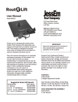
1
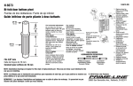
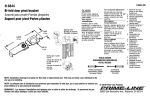
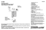
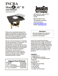
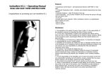
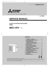
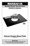
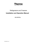
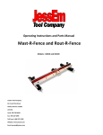
Rout R Lift™ PRESTIGE User Manual 100 Caplan Avenue, Units 14 & 15, Barrie, Ontario L4N 9J2 Model #02320 Thank you for choosing this product from JessEm Tool Company. We appreciate your support and hope that our product serves you well. This product is designed to provide many years of reliable service provided it is used as intended and taken care of. This user manual will assist you in assembly and general operation of this product. It is not our intent to teach you about woodworking. It is assumed that you are an experienced woodworker with the basic skills and experience necessary to use this product safely. If after reading the following instructions, if you are unsure or uncomfortable about safely using this product we urge you to seek additional information through widely available woodworking books or classes. IMPORTANT! Read and understand the contents of this manual before assembly or operation of this product. 800-436-6799 Toll Free 705-726-8233 Local Phone 705-726-7519 Fax Email: [email protected] Website: www.jessem.com As part of our Continuous Product Improvement Policy, JessEm products are always advancing in design and function. Therefore there may be differences between what is shown in our catalogs, website or at retail display and what is sold at time of purchase. We reserve the right to make positive changes to our products at our discretion. CONTENTS: 1-Rout-R-Lift™ Prestige 1-Height Adjustment Handle 10 - 1/4-28 x ¼” Leveling Set Screws 1- 5/32 Hex Key Also includes 1-Insert Ring, 1-Insert Ring Wrench, 1/8” Hex Key, 1-Start Pin, 3/16” Hex Key 4 - M6 x 30mm Mounting Screws (Used for Mast-R-Top #03004A and #03005) 4 – ¼-20 X 1” Flat Head Cap Screw (Used for Mast-R-Top Model #03004/#03006) IMPORTANT SAFETY PRECAUTIONS Before operating any router, read and understand all safety instructions in the owner’s manual that came with the router. If you do not have a manual, contact the manufacturer and obtain one before using any power tool. Always wear eye protection in compliance with ANSI safety standards when operating any power tool. Always use proper guards and safety devices when operating power tools and machinery. Carefully check router bits before each use. Do not use if damage or defect is suspected. Suggested Router Bit Speeds Bit Diameter Max. Speed 1” (25mm) 24,000 RPM 1-1/4” - 2” (30-50mm) 18,000 RPM 2-1/4” - 2-1/2” (55-65mm) 16,000 RPM 3” - 3-1/2” (75-90mm) 12,000 RPM ROUTER SAFETY PRECAUTIONS Never force the bit or overload the router beyond the expectations of the tool. Be sure that at least 3/4 of the shank length is inserted securely in the router collet. Do not exceed the recommended RPM for any router bit. Do not wear loose clothing or jewelry that may catch on tools or equipment. Unplug the tool or machine when mounting or making any adjustments to mechanical performance Never bottom out the bit in the collet. Allow 1/8” clearance between shank and bottom of collet. Always make sure the fence on your router table is locked into position before each use. Use reduced RPM speeds for large diameter bits. Always rout in two or more passes when large amounts of stock must be removed. DO NOT USE A CORDLESS DRILL TO RAISE AND LOWER THE LIFT CARRIAGE. THE AMOUNT OF FRICTION WILL CAUSE PREMATURE WEAR OF THE THREADS AND WILL VOID WARRANTY 1 INSTALLING THE ROUTER – SEE INDIVIDUAL ROUTER ADJUSTMENTS ON PAGES 3 & 4 PRIOR TO INSTALLING YOUR ROUTER ROUTER LEGEND Your Rout-R-Lift Prestige is predrilled for many routers. The first step is to remove the carriage plate from the Lift. Place the crank handle into the hex hole in the lift’s dial on the top plate. Crank the lift carriage down approximately 2 cm from the top plate. You will need a little bit of room to remove the carriage plate from the Mast-R-Lift II Prestige. (Figure 1) Router Hole Pattern Hitachi M12V & M12V2 1 DeWalt 625, ELU 3337-9 2 Bosch 1617, 1604 3 Bosch 1617, 1613 (Thru Hole) 4 Makita RP2301FC 5 Festool OF 1400 EQ 6 Festool OF 1010 EQ 7 Table 1 Each router has a unique hole pattern. For example, if you have a Hitachi M12V, locate all the #1 holes on the carriage plate. These will be your mounting holes. Figure 1 1. 4. With the router upright, place the carriage plate on the router base and align the hole pattern in your base with the corresponding # on the carriage plate (provided you have one of the noted routers). Keep in mind your handle location of your router. The handles should be roughly in line with the two engraved lines on the carriage plate (the side with the engraved circles) 5. Once aligned; with the screws provided, tighten the Rout-R-Lift Prestige carriage to your router.(Figure Remove the five (five) 1-1/2” Cap Screws and one (1) 1” Cap Screw from the carriage brackets (Figure 2 and 3) Figure 2 Figure 3 2. Remove the carriage plate from the Lift. 3. Turn the carriage plate over and locate your router from the legend on the top of the plate. See Figure 4 and Table 1. Figure 5 Figure 4 6. Slide the carriage back on to the lift. 7. With two ¼-20 x 1-1/2” Cap screws you removed in Step 1, re-engage into the left carriage bracket. (Figure 6) 2 Your Mast-R-Lift II Prestige is ready to be installed into your table top. Each router has its own unique characteristics and each router has its own individual adjustments and modifications may be required to your router in order to use the Mast-R-Lift II Prestige. Once you have read and understand any special instructions for the router you are mounting, follow steps 1 through 9. Figure 6 8. Mounting a DeWalt 625 Pull up on the router until it meets the right carriage bracket. Now secure with three (3) 11/2 Cap screws and one (1) 1” cap screw (Figure 7) Figure 9 Figure 10 Special Instructions: Figure 1both handles from your router before mounting. Remove Figure 7 9. With your router and carriage secured to the lift, take your adjustment handle and wind the carriage all the way to the top plate 10. Now engage the plunge mechanism in the router by pushing your router all the way down and locking it in this position. Mounting Screws: Three (3) 6mm x 15 mm long (included) Mounting the Bosch 1613 EVS Figure 11 Figure 12 Special Instructions: Depth stop knob and bar need to be removed. Mounting Screws: Three (3) 6mm x 25 mm (included) Three (3) 6mm hex nuts (included) Figure 8 3 BOSCH 1617 EVS – PLUNGE BASE Special Instructions: Remove the handle without the switch. Leave sub-base on when mounting to the carriage. Mounting Screws: Four (4) 4mm x 16mm HITACHI M12V & M12V2 Figure 13 Figure 14 Special Instructions: Handles need to be removed. Depth stop knob and bar need to be removed Mounting Screws: Three (3) 6mm x 25 mm (included) Three (3) 6mm hex nuts (included) BOSCH 1617 EVS – FIXED BASE Figure 20 Figure 19 Special Instructions: Remove Turret stop adjustment knob. Remove handle that does not have speed adjustment. Lower the Lift carriage before installing and removing from your table top. Mounting Screws: Four (4) 5mm x 10mm (included) FESTOOL OF 1400 Figure 15 Figure 16 Special Instructions: No special instructions for this router Mounting Screws: Four (4) 4 mm x 10 mm (included) MAKITA RP 2301FC Figure 21 Figure 22 Special Instructions: No Special Instructions Mounting Screws: Two (2) 6mm x 14mm (included) Five (5) 4 mm x 8mm (included) Figure 17 Figure 18 4 FESTOOL OF 1010 With the Rout-R-Lift Prestige in the table top opening, install (10) set screws into the holes around the lift perimeter. Adjust (Figure 25) the four corners first to align the lift surface to the table surface so that both are flush. Adjust the remaining set of screws on the sides to provide added support. ADJUSTING THE FIT IN THE TABLE PORT Figure 23 Figure 24 Special Instructions: No special instructions for this router Your Rout-R-Lift™ Prestige comes with adjustable snugger buttons to allow for a tight fit in the table top opening and eliminate any movement of the plate. Use the 1/8” hex key provided to loosen the cap screws on the snugger button. Slide the button towards the outer part of the plate and check for fit. Adjust again if necessary. (Figure 26) Mounting Screws: Four (4) 4mm x 8mm (included) The Rout-R-Lift Prestige is manufactured to precise tolerances. Once your router is installed and you do not find your Lift is as smooth as it should be do the following adjustment. First: raise the Lift carriage with the router installed to a position close to the top plate. Then, loosen the five 1/4-20 low head socket screws holding the spindle assembly and guide shaft a quarter turn, then retighten. This relieves any stress on the shafts to center themselves with respect to the carriage after the router is installed ensuring there is no resistance in the movement of the carriage up and down. INSTALLING A JESSEM LIFT IN A CUSTOM ROUTER TABLE APPLICATION A JessEm Rout-R-Lift Prestige is similar to using a router mounting plate. Your table top must have a port machined into the top. JessEm offers solid phenolic router tables tops with pre-machined ports for all JessEm router lifts. If you are installing this Lift in a custom table application you will have to fabricate this opening yourself. JessEm offers a separate template for this operation. See your JessEm distributor for the proper template for your JessEm Rout-R-Lift Prestige. Figure 26 TAB-LOC PHENOLIC INSERT RINGS Your Rout-R-Lift™ Prestige comes with one 2” insert ring with a pre-drilled center hole. Additional ring sets are available with different diameter pre-drilled holes and/or no pre-drilled holes for creating your own custom center hole diameters. See your JessEm distributor for these and other accessories. 1. Place the insert ring into the center hole of the Lift’s top plate (Fig. 27). 2. With the insert wrench provided, insert the prongs of the wrench into the corresponding holes in the insert ring and turn the insert ring counter clockwise to tighten. LEVELING THE LIFT IN THE TABLE TOP Figure 27 Figure 25 Turn the insert wrench clockwise to loosen and remove the ring. If the insert ring becomes too tight to loosen with hand pressure, a tap clockwise on the insert wrench with a block of wood will loosen it. 5 USING YOUR ROUT-R-LIFT™ PRESTIGE To raise your router, turn the height adjustment handle clockwise. To lower, turn the handle counter-clockwise. Keep in mind that one complete revolution equals 2mm of change. When your adjustment is complete, remove the handle and place somewhere off the work surface for safety. 1. Turn the Lift upside down on a table with the threaded height adjustment rod facing you. 2. Remove the ¼ x 1” Cap Screws from the Carriage Nut Cover (Figure 30) and remove the cover and o-ring. USING THE FRICTION LOCK ON YOUR ROUT-R-LIFT™ PRESTIGE With the Rout-R-Lift™ Prestige you have the added benefit of locking your Lift in a desired position for long term routing operations and having the comfort in knowing the position you have set is locked in place. Figure 30 To lock your lift turn lift handle clockwise. 3. Slide the carriage all the way up towards the top plate revealing the carriage nut, o-ring and antibacklash nut. 4. Thread the carriage nut and antibacklash nut further up the threaded rod to have better access Figure 28 To unlock your lift, turn the lift handle counterclockwise. Figure 29 Figure 31 RE-ADJUSTING THE THREAD TENSION All JessEm Lifts feature our patented thread tensioning design. Thread tension is set at the factory and depending on the amount of use you may have to reset this adjustment periodically, depending on the amount of tension you desire. If the bit height ever begins to change (or drop) during use, the thread tensioning likely needs to be reset. 5. Turn the carriage nut clockwise, applying pressure to the o-ring ensuring when you complete your adjustment that the slot in the carriage nut aligns with one of the slots on the antibacklash nut (Figure 31) 6. Slide the carriage back up ensuring the nib in the carriage aligns with the slot in the carriage nut (Figure 32) 6 Figure 35 3. Remove router sub base Figure 32 7. Place back the o-ring and carriage nut cap and with the scews you removed in Step 2 (Figure 30) fasten the carriage nut cap securely. Mounting your router to a blank Rout-RLift Prestige carriage plate Figure 36 4. Centre the router sub base on the blank plate, aligning the two marks made in step 1. (Figure 36) and centre the sub base to the engraved rings on the blank plate. Figure 33 1. Place the optional blank mounting plate on Lift and place your router in position ensuring handles, switch and variable speed are in optimal position. Apply strip of masking tape to the router and blank plate and draw a line referencing this position. (Figure 33) Figure 37 5. Secure the router sub base to the blank plate with masking tape or clamp in this position. (Figure 37) Figure 34 2. Turn the router upside down and transfer this mark to the router sub base. (Figure 34) 7 JESSEM TOOL LIMITED WARRANTY 2 1 4 3 Figure 38 6. Locate the correct drill bit size and transfer the mounting hole locations from your sub base to the blank plate. Use your drill to just spot these holes on your blank plate then remove the sub base and finish drilling the holes. From the other side of the blank plate counter sink or counter bore these holes to suit the router mounting screws. You may need to source the correct size screws at your local hardware store. (Figure 38) All JessEm products are warranted to be free from defects in material and workmanship. JessEm will repair or replace any product which upon inspection proves to be defective for a period of (1) year from dated receipt and proof of purchase. All warranty claims should be made direct to JessEm Tool Company. Contact JessEm for a warranty claim return authorization and instructions to proceed. The consumer is responsible for shipping costs to return product to JessEm Tool Company. We will repair or replace the product at our discretion and JessEm Tool will return shipment to you at no charge. A B D C E F G WARRANTY LIMITATIONS This warranty does not cover: Repairs or alterations made or attempted by anyone other than JessEm Tool Company or an authorized JessEm service professional. Normal wear and tear Abuse, misuse or neglect. Improper care or maintenance. Continued use after partial failure. Products that have been modified in any way. Products used with improper accessories. Premature thread wear due to adjusting height with electric or cordless drill. Figure 39 7. Remove plate risers from the predrilled router mounting plate that came with your lift and install on the blank plate. Follow instructions 6 through 10 to install the router mounting plate (carriage) on your Rout-R-Lift Prestige. 8