1
Report No: T130222L03-B-RE
4 TEST METHODOLOGY
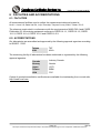
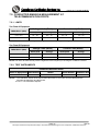
4.1. DECISION OF FINAL TEST MODE
1.
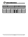
The following test mode was scanned during the preliminary test:
Pre-Test Mode
Mode 1: Data Link
2.
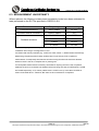
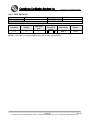
After the preliminary scan, the following test mode was found to produce the highest
emission level.
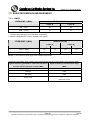
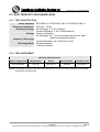
Final Test Mode
Emission
Immunity
Conducted Emission
Mode 1 (1200 x 900 Resolution)
Radiated Emission
Mode 1 (1200 x 900 Resolution)
Mode 1 (1200 x 900 Resolution)
Then, the above highest emission mode of the configuration of the EUT and cable was
chosen for all final test items.
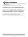
Remark: The EUT consumes power from host, which designed with AC power supply
of rating 100-240VAC, 50/60Hz. For radiated emission evaluation, 230Vac/50Hz,
120Vac/60Hz, 110Vac/60Hz and 100Vac/50Hz had been covered during the pre-test.
The worst radiated emission 30MHz ~ 1GHz was found at 110Vac/60Hz and recorded
in the applies test report.
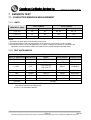
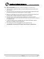
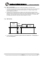
4.2. EUT SYSTEM OPERATION
1
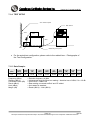
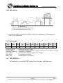
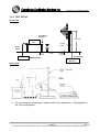
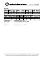
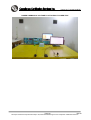
Setup the EUT and simulators as shown on 5.2.
2
Turn on the power of all equipment.
3
The module device driver was exercised to play music.
4
Operates the Camera and Wireless LAN functions of EUT.
5
6
EUT will read data from hard disk and then writes the data into hard disk, same as external
Hard Disk.
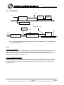
The EMI (File name: TERMINAL) test program was loaded from EUT and executed in
“Linux”mode.
7
EUT will sends “H” pattern to monitor, the monitor will show “H” pattern on the screen.
8
Repeat the above procedure (3) to (9).
Note: Test program is self-repeating throughout the test.
Page 8
Rev.00
This report shall not be reproduced except in full, without the written approval of Compliance Certification Services.