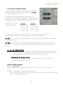
1
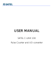
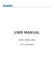
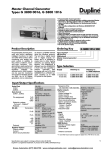
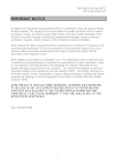
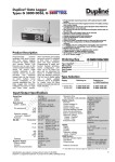
USER MANUAL
SATEL C-LINK 100
Pulse Counter and I/O-converter
SATEL C-LINK 100
User Manual, Version 2.0
TABLE OF CONTENTS
TABLE OF CONTENTS ..................................................................................................... 2
IMPORTANT NOTICE....................................................................................................... 3
PRODUCT CONFORMITY ................................................................................................ 4
WARRANTY AND SAFETY INSTRUCTIONS........................................................................ 5
1 GENERAL ..................................................................................................................... 6
1.1
SATEL C-LINK 100 PULSE COUNTER AND I/O -CONVERTER .......................................... 6
2 SPECIFICATIONS........................................................................................................ 7
3 FUNCTIONS .............................................................................................................. 8
SCREW CONNECTOR FUNCTIONS......................................................................................... 8
3.1 OPERATIONAL VOLTAGE, 9 – 30 VDC ......................................................................... 8
3.2 ALARM OUTPUT, AL OUT......................................................................................... 8
3.3 + OUT ............................................................................................................... 8
3.4 DIGITAL INPUTS, I1…I4, AND OUTPUTS O1…O4 ........................................................ 8
3.5 PULSE INPUTS, FAST/SLOW .................................................................................... 8
3.6 INDICATORS .......................................................................................................... 8
3.7 DIP-SWITCHES ...................................................................................................... 9
3.7.1 How to set the channel .................................................................................. 10
4 SETTINGS FOR PULSES IN POINT-TO-POINT MODE ................................................. 12
4.1 PULSE INPUT ........................................................................................................ 12
4.1.1 Trigger settings - Time and Pulse.................................................................... 12
4.1.2 Input Pulse divider ......................................................................................... 12
4.2 PULSE OUTPUTS ................................................................................................... 13
5 OPERATION ............................................................................................................. 14
5.1 POINT- TO-POINT ................................................................................................ 14
5.1.1 Updating Digital messages ............................................................................ 14
5.1.2 Updating Pulse messages .............................................................................. 14
5.1.3 Beginning with Point-to-Point operation ......................................................... 14
5.2 POINT-TO-MULTIPOINT ......................................................................................... 15
5.2.1 Updates ........................................................................................................ 15
5.3 STARTING THE MULTIPOINT OPERATION...................................................................... 15
6 FACTORY SETTINGS ................................................................................................. 16
7 CONNECTION EXAMPLES ........................................................................................ 17
8 ACCESSORIES .......................................................................................................... 18
9 EXTENSION MODULES ............................................................................................. 19
2
SATEL C-LINK 100
User Manual, Version 2.0
IMPORTANT NOTICE
All rights to this manual are owned solely by SATEL OY (later called also SATEL). All rights reserved.
The copying of this manual without the written permission from the owner of the rights by printing,
copying, recording or by any other means or the full or partial translation of the manual to any
other language including all programming languages using any electrical, mechanical, magnetic,
optical, manual or other methods or devices is forbidden.
SATEL reserves the right to change the technical specifications or functions of its products or to
discontinue the manufacture of any of its products or to discontinue the support of any of its
products without any written announcement and urges its customers to ensure, that the information
at their disposal is valid.
SATEL software and programs are delivered ”as is”. The manufacturer does not grant any kind of
warranty including guarantees on saleability and guarantees pertaining to applicability to a certain
application. Under no circumstances is the manufacturer or the developer of a program responsible
for any possible damages caused by the use of a program. The names of the programs as well as
all copyrights relating to the programs are the sole property of SATEL. Any transfer, licensing to a
third party, leasing, renting, transportation, copying, editing, translating, modifying into another
programming language or reverse engineering for any intent is forbidden without the written
consent of SATEL.
SATEL PRODUCTS HAVE NOT BEEN DESIGNED, INTENDED NOR INSPECTED TO
BE USED IN ANY LIFE SUPPORT RELATED DEVICE OR SYSTEM RELATED
FUNCTION NOR AS A PART OF ANY OTHER CRITICAL SYSTEM AND ARE
GRANTED NO FUNCTIONAL WARRANTY IF THEY ARE USED IN ANY OF THE
APPLICATIONS MENTIONED.
3
SATEL C-LINK 100
User Manual, Version 2.0
PRODUCT CONFORMITY
SATEL C-LINK 100
Hereby, SATEL Oy declares that the above-mentioned product is in compliance with the essential
requirements and other relevant provisions of Directive 89/336/EEC. Therefore the equipment is
labelled with the following CE-marking.
4
SATEL C-LINK 100
User Manual, Version 2.0
WARRANTY AND SAFETY INSTRUCTIONS
Read these safety instructions carefully before using the product.
Warranty will be void, if the product is used in any way, which is in contradiction with the
instructions given in this manual, or if the housing of the radio modem has been opened or
tampered with.
The radio modem is to be used only on frequencies allocated by local authorities and without
exceeding the given maximum allowed output power ratings. SATEL is not responsible, if any
products manufactured by it are used in unlawful ways.
The devices mentioned in this manual are to be used only according to the instructions described in
this manual. Faultless and safe operation of the devices can be guaranteed only if the transport,
storage, operation and handling of the devices is appropriate. This also applies to the maintenance
of the products.
To prevent damage both the radio modem and any terminal devices must always be switched OFF
before connecting or disconnecting the serial connection cable. It should be ascertained that
different devices used have the same ground potential. Before connecting any power cables the
output voltage of the power supply should be checked.
Salo, Finland 2010
5
SATEL C-LINK 100
User Manual, Version 2.0
1 GENERAL
1.1 SATEL C-LINK 100 Pulse Counter and I/O -converter
The SATEL C-LINK 100 is a Point-to-Point or Point-to-Multipoint transparent pulse counter and I/Oconverter. The device works together with SATELLINE modems. In Point-to Point transmission a
digital status information or count of pulses can be sent through the radio modem to be output in
the other end. Point-to-Multipoint transmission is possible adopting software suitable for the SATEL
C-LINK 100.
U pper row connectors
O1…O4
SLOW, FAST
O utput indicators
ON
O1-O4, SLOW, FAST
DIP -Switches
PRTCL, Protocol
Digital outputs. Relay contacts.
Pulse Outputs.
SLOW= 5 Hz, contact closures.
FAST= 10 kHz, opto coupler.
Power ON/OFF indicator
Digital and Pulse outputs
P-to-MP, Point-to-Multipoint
P-to-P, Point-to-Point
ADDRESS/CHANNEL/
DIVIDER
Multipoint address / Channel
select*) / Pulse divider
BAUD
Baud rate settings
3 DE
1=ON, 0=OFF Alarm Delay
4 SM
1=ON, 0=OFF Safe Mode
5 PT
1=Pulse
Pulse / Time Transmission
0=Time
678 TIME/ F.PULSE
Transmission interval for Pulses /
Pulse divider
Input indicators
ALARM
Indicator for failed transmission
I1...I4, SLOW, FAST
Digital and Pulse inputs
Lower row connectors
9-30 VDC/ - +
AL OUT
+ OUT
I1…I4
SLOW +
FAST +
-
Supply Voltage
Alarm output
Common + for Digital inputs
and Extension Units
Digital inputs
Slow Pulse input, max. 100 Hz
Fast Pulse input, max. 10 kHz
Common Ground for Pulse inputs
D-15 connectors
RADIO MODEM
D-15 male for radio modem
EXTENSION
D-15 female for extension units
*) Applicable only with SATELLINE-1870 and -1870E radio
modems
6
SATEL C-LINK 100
User Manual, Version 2.0
2 SPECIFICATIONS
FEATURE
min-max
typical
note
Voltage
Power consumption
Serial Interface
Extension Interface
Response time
Operational temperature
Transfer rates
+9…+30 Vdc
0.3...1.0 W VA
RS-232 ± 15 Vdc
-0.3…+6 Vdc
< 250 ms
-25…+55 oC
2400 – 19200 bps
24 Vdc, typical
± 6 Vdc
0.5…5 Vdc
< 300 ms
active RS232
active TTL
@ 9600 bps
PULSE COUNTER
Slow Inputs, 1 pc
- minimum pulse width
Fast Inputs, 1 pc
- minimum pulse width
Slow Output
Fast Output
max. 2 kHz
1 ms
max. 10 kHz
5 μs
max. 5 Hz
max. 10 kHz
50/50 pulse rate
50/50 pulse rate
contact closure, 1A @ 30 VDC
Optoisolated, 30 mA.
TRANSMISSION INTERVALS
Time based
continuous ... 7 days
Pulse count based
selectable
DIGITAL SIGNALS
Inputs, 4pcs
Outputs, 4pcs
0 – 30 Vdc
0 – 250 Vac / 2 A
INDICATORS
Indicators
Power ON/OFF, Digital/Analogue IN/OUT, Alarm, Pulse IN/OUT.
OTHER OUTPUTS
Alarm Output
0 – 30 Vdc / 30 mA
GENERAL
Casing
Connectors
Size L x W x H and weight
Mounting
IP
Modem compatibility
Stainless steel
D-15 for SATELLINE radio modem, D-15 for extension module
123 x 85 x 30 mm, 120 g
Wall plate or DIN-rail
IP-20
SATELLINE-2ASxE, -2ASc, 3AS-serie, SATELLINE-1870 and -1870E
0 – 30 Vdc
0 – 250 Vac / 2A
24 Vdc / 20 mA
C-LINK 100 D-15 connector “Radio Modem”
Direction
Signal
Pin
+VB, DTR
1, 14, 15
GND, SGND
7, 8
RD
9
TD
11
RTS
13
CTS
6
7
resistive 4-5 k,
relay contacts
active + 30 mA
SATEL C-LINK 100
User Manual, Version 2.0
3 FUNCTIONS
Screw connector functions
3.1 Operational Voltage, 9 – 30 Vdc
o The Supply Voltage is connected to connectors 9 – 30 VDC (-) and (+).
o + OUT is internally connected to + VDC through an internal fuse. The supply Voltage
for the Extension Units must be taken from the connector +OUT.
3.2 Alarm output, AL OUT
o The AL OUT is activated, when 3 consecutive transmissions has been failed. When
activated the output state goes to +VDC. When a C-LINK 100 sends information to
another C-LINK 100, it requires an acknowledgement message. In case there is a fail in
transmission and the C-LINK does not receive an acknowledgement message, the
transmission will be retransmitted, maximum 3 times or until an acknowledgement is
received.
3.3 + OUT
o A Voltage output to the extension units etc. This line is internally connected to +VDC
through a fuse.
3.4 Digital Inputs, I1…I4, and Outputs O1…O4
o Inputs,
o 4pcs. Activated with + voltage.
o Outputs,
o 4pcs. Open relay contacts. Can be connected to any 0 - 250 VAC / 2A load.
3.5 Pulse Inputs, FAST/SLOW
o Inputs
o SLOW. For slow pulses. Maximum input frequency is 2 kHz. Maximum number of the
pulses in the memory 4 x 10⁹.
o FAST. For fast pulses. Maximum frequency is 10 kHz. Maximum number of the pulses
in the memory is 4 x 10⁹.
o Outputs,
o SLOW. For slow pulses. Output frequency rate is 5Hz. Relay output (1A @ 30 VDC).
o FAST. For fast pulses. Output frequency rate is 10kHz. Open collector, 30 mA.
3.6 Indicators
o ON
o Power ON/ OFF. Illuminated when +VCD is connected.
o O1…O4, PO1, PO2
8
SATEL C-LINK 100
User Manual, Version 2.0
o Showing the status of the Output. Illuminated when output is activated.
o ALARM
o Illuminated, if a fail in transmission has occurred. When the transmitting C-LINK 100
sends information to another C-LINK 100, it requires a confirmation to the sent
messages. In case there is a fail in transmission and the C-LINK 100 did not receive
a confirmation, the transmission will be resend until a confirmation is received,
maximum 3 times. 3 consecutive fails switches the Alarm LED ON.
o I1…I4, PI1, PI2
o Showing the status of the Input. Illuminated when the input is activated.
3.7 DIP-Switches
Upper row DIP-switches
1 PRTCL, Protocol-switch
o 1= P-to-MP for Point-to-Multipoint (Master-Slave)-operation.
o 0= P-to-P for Point-to-Point-operation
ADDRESS/ CHANNEL/ DIVIDER
1, 2, 4, 8, 16, 32, 64 ADDRESS
o For selecting address in the Point-to-Multipoint-operation.
o Example:
Ch (1)
O N OFF OFF OFF OFF OFF OFF
1
2
4
8 16 32 64
Ch (5)
O N OFF O N OFF OFF OFF OFF
1
2
4
8 16 32 64
o Maximum number of addresses is 127.
1, 2, 4, 8 CHANNEL (works only together with SATELLINE-1870 and -1870E)
o Used at Point-to-Point-operation together with SATELLINE-1870 and -1870E radio
modems to select an operation channel. In order to change the channel the SLcommands of the SATELLINE-1870 and -1870E must be ON.
Note!
Point-to-Point Mode
Check that all ADDRESS switches are OFF when the C-LINK 100 is used with
any other than SATELLINE-1870 and -1870E radio modems.
(If any of the address DIP-switches are ON, it will not cause any harm, but the C-LINK 100
will not operate).
9
SATEL C-LINK 100
User Manual, Version 2.0
3.7.1 How to set the channel
When the power is turned ON, the C-LINK 100 reads the
channel information from the ADDRESS switches 1 -2-4-8.
The default setting is 0-0-0-0.
The channel is changed by turning first the power OFF,
selecting the channel and turning power ON. The channel is
selected from the DIP-switches ADDRESS-CHANNEL-DIVIDER
for example 1-0-0-0. 1=ON=up, 0=OFF=down.
ADDRESS-CHANNEL-DIVIDER
Channel numbering:
1 2 4 8
0 0 0 1 =ch1
0 0 1 1= ch3
0 1 0 1= ch5
0 1 1 1= ch7
1 0 0 1= ch9
1 2 4 8
0 0 1 0 = ch2
0 1 0 0 = ch4
0 1 1 0 = ch6
1 0 0 0 = ch8
1 0 1 0 = ch10
The channel must be same for both C-LINK 100 units before turning the power ON.
When the power is turned ON the operational channel has been selected.
NOTE1! 0 0 0 0 = disable. This setting must be used, if the radio modem does not support the
channel select feature.
NOTE2! The C-LINK 100 unit will not operate with the following settings: 1011, 1100, 1101,
1110 or 1111. The power ON indicator starts to blink in case any of these settings has been
chosen.
16, 32, 64 (678) DIVIDER
o Used at Point-to-Point-operation to select the divider factor for SLOW pulses. This
approach uses an electronic divider to adjust the pulse rate. A divider counts pulses
and transmits one pulse when the preset divider factor is reached.
Settings for the Divider Factor
o The Divider Factor can be set by the DIP-switches 6,7,8 =16, 32, 64 of the
ADDRESS/ CHANNEL/ DIVIDER.
Lower row DIP-switches
1, 2
BAUD kb/s
The Baud Rate can be selected as follows:00=2.4, 10=4.8, 01=9.6, 11=19.2 kbps
3 DE
Alarm setting. Immediate / Delayed Alarm
In case of a failure in the transmission, the Alarm response can be selected from immediate
Alarm to 10 minutes delayed Alarm.
10
SATEL C-LINK 100
User Manual, Version 2.0
4 SM Safe Mode setting. Unchanged state / Safe Mode state
In case a failure in transmission, the outputs can be set to remain their status (unchanged) or
change to “Safe Mode” which will switch all outputs to OFF-position. Safe Mode timing
follows the setting of the switch 3 DE, so it can be immediate or delayed by 10 minutes.
The functions of the Dip–switches 3 and 4 are set as follows:
3DE 4SM
0
0 = Immediate Alarm / No Safe Mode
0
1 = Immediate Alarm / Immediate Safe Mode
1
0 = Alarm delayed by 10 minutes / No Safe Mode
1
1 = Alarm delayed by 10 minutes / Safe Mode delayed by 10 minutes
5 PT
Pulse/ Time for selecting the transmission trigger.
1= Pulse triggering. 0= Time triggering.
6, 7, 8 TIME / F.PULSE
o Settings for Time based Point-to-Point transmission and divider for fast Pulse input.
o Time based setting defines the transmission interval. The selected time interval is valid
for both pulse counters.
o Pulse based setting defines the counted number of pulses when the transmission for
Fast Pulses is triggered.
11
SATEL C-LINK 100
User Manual, Version 2.0
4 SETTINGS FOR PULSES IN POINT-TO-POINT MODE
The C-LINK 100 has 2 different ways for handling the triggering of the pulse transmission in Pointto-Point mode. The triggers are either Time or Pulse.
4.1 Pulse Input
4.1.1 Trigger settings - Time and Pulse
Time triggering: DIP-switch 5 PT =0.
DIP 6 7 8
0
0
0
0
1
1
1
1
0
0
1
1
0
0
1
1
0
1
0
1
0
1
0
1
Time
Continuous (= No time selected)
2 sec
10 sec
1 min
1 hour
12 hours
24 hours
7 days
When the preset time has been reached, the C-LINK unit sends a message to the other C-LINK unit,
which starts to send out the pulses one by one. The SLOW output speed is 5 Hz. The FAST output
speed is 10 kHz.
4.1.2 Input Pulse divider
Both inputs (SLOW and FAST) have their own Pulse Dividers for transmission triggering. When the
preset divider factor has been reached, the C-LINK unit sends one pulse to the other C-LINK unit.
Pulse triggering: DIP-switch 5 PT =1.
Settings for FAST pulses
Lower row
6 7 8
Divider factor
Settings for SLOW pulses
Upper Row
16 32 64 Divider factor
0
0
0
0
1
1
1
1
0
0
0
0
1
1
1
1
0
0
1
1
0
0
1
1
0
1
0
1
0
1
0
1
Direct
10 pulses
50 pulses
100 pulses
500 pulses
1000 pulses
5000 pulses
10 000 pulses
NOTE!
SLOW pulse divider is valid also for time triggering.
FAST pulse divider is valid only for pulse triggering.
12
0
0
1
1
0
0
1
1
0
1
0
1
0
1
0
1
Direct
2 pulses
5 pulses
10 pulses
20 pulses
50 pulses
100 pulses
Programmable (by SATELLINK
PC Pro)
SATEL C-LINK 100
User Manual, Version 2.0
4.2 Pulse Outputs
When the C-LINK 100 unit has got a pulse message from the other C-LINK 100 unit, it’ll send the
pulses to its output. The SLOW output speed is 5 Hz. The FAST output speed is 10 kHz.
NOTE!
Due to the data rate between the radio modem and the C-LINK 100, the maximum continuous
transfer rate is limited to 2 Hz i.e. the incoming frequency must be the same or be less than the
throughput of the two C-LINK 100 units. The maximum number of pulses (P max) for the preset time
is calculated as follows:
Slow output
P max. = T (in seconds) x Divider x 5
Example1: Time setting is 5 min. Divider is 1.
Example2: Time setting is 5 min. Divider is 10.
Fast output
P max. = T [in seconds] x Divider x 10 000
Example1: Time setting is 5 min. Divider is 1.
Example2: Time setting is 5 min. Divider is 10.
300 sec. x 1 x 5.
300 sec x 10 x 5.
Pmax = 1500 pulses.
Pmax = 15 000 pulses.
300 sec x 1 x 10 000. Pmax = 3 million
300 sec x 10 x 10 000. Pmax = 30 million
13
SATEL C-LINK 100
User Manual, Version 2.0
5 OPERATION
Operation mode is selected by the PRTCL-switch. The operations are Point-to-Point or Point-toMultipoint. In Point-to-Point operation the system consists of one pair of units and the changes of
the inputs at one end will be sent to the outputs on the other end.
In Multipoint mode the Main Controller commands one or more (max 127) sub-stations.
5.1 Point- to-Point
Point-to-point operation is between two units. The inputs of one C-LINK 100 will be transferred
to the outputs of the other C-LINK 100.
5.1.1 Updating Digital messages
Digital information (relay, switch etc.) will be sent to the other unit always, when there is a
change of a state at the input.
5.1.2 Updating Pulse messages
Pulse information will be sent according to the Time/ Pulse settings.
5.1.3 Beginning with Point-to-Point operation
o Connect SATELLINE -modem to C-LINK 100 directly to RADIO MODEM -connector or
using an interface cable
o The “PRTCL”- switch must be “0”, P-to-P.
o Before connecting the device to a power supply, connect first all inputs and outputs that
are to be used.
o Select the SATEL C-LINK 100 BAUD-rate. 00=2.4, 10=4.8, 01=9.6, 11=19.2 kbps
o Check that the radio modem baud rate is same as for C-LINK and that other parameters
are “9600-N-8-1” (9600 bps is a default setting, but can be changed to be any of the
BAUD-rates given above).
o Set the message transmission interval by using TIME/PULSE -switches as described
above.
o When both units have these basic settings (TIME/PULSE can be different on both units)
the supply voltage can be connected.
o Note! Check that all ADDRESS switches are OFF when the C-LINK 100 is used with any
other than SATELLINE-1870 and -1870E radio modems.
14
SATEL C-LINK 100
User Manual, Version 2.0
5.2 Point-to-Multipoint
In this mode the Main Controller can drive one or more sub-stations (max. 127 pcs)
5.2.1 Updates
The updates are controlled by the Main Controller, which sends messages to the sub-stations or
asks status information from them. As the Main Controller is controlling the units the
TIME/PULSE settings of the C-LINK 100 are not valid.
There are two options on how to use the Point-to-Multipoint with the C-LINK 100:
1. The C-LINK 100 protocol integrated to your own system.
2. The system is controlled by the SATELLINK PC or PC Pro-software.
5.3 Starting the Multipoint operation
o Connect one SATELLINE radio modem to the PC COM-Port. This one will be the Main
Controller.
o Connect the C-LINK 100 Sub-station units to the SATELLINE radio modems directly to CLINK 100 Radio Modem connector or using an interface cable
o The “PRTCL”- switch must be “1”, P-to-MP.
o Before connecting the device to a power supply, connect first all inputs and outputs that are
to be used.
o Select the SATEL C-LINK 100 BAUD-rate. 00=2.4, 10=4.8, 01=9.6, 11=19.2 kbps
o Check that the radio modem baud rate is same as for C-LINK and that other parameters are
“9600-N-8-1” (9600 bps is a default setting, but can be changed to be any of the BAUDrates given above).
o Set the individual addresses to all sub-stations. (As this is a Main Controller <–> substation operation, all Sub-stations have to be addressed). All sub-stations must have different
address.
o Open the Point-to-Multipoint program suitable for the SATEL C-LINK 100, for example
SATELLINK PC or SATELLINK PC Pro.
Please contact local SATEL distributor or visit SATEL’s web site in order to get information of the
multipoint commands.
15
SATEL C-LINK 100
User Manual, Version 2.0
6 FACTORY SETTINGS
The C-LINK 100 I/O -converter is shipped with the following default settings (unless specifically
ordered with settings other than those listed below):
FIXED SETTINGS DEFINED AT THE TIME OF ORDER
PRTCL, protocol-switch
ADDRESS
BAUD
3 DE, Alarm Delay
4 SM, Safe Mode
5 PT, Pulse/Time
TIME, transmission interval
P-to-P
0000000
01
0
0
0
000
= Point-to-point
= No address
= 9600 bps
= No delay
= Safe Mode OFF
= Time
= Continuous
16
SATEL C-LINK 100
User Manual, Version 2.0
7 CONNECTION EXAMPLES
Point-to-Multipoint
Point-to-Point
Outputs, upper row screw
contacts
o DIGITAL OUTPUTS are open
contact closures, 2 A. 12…24 DCV
or 230 ACV.
o SLOW Pulse output is open
closure, as above. The maximum
output frequency is 5 Hz.
o FAST pulse output is optoisolated and needs to be connected
to the + VDC.
Inputs, lower row screw
contacts
o 12-24 VDC Supply Voltage to
pins - +.
o AL out goes high, when an alarm
is activated.
o + OUT is Supply Voltage for
Extension units etc.
o Digital inputs are activated with
+ VDC. High state threshold is 7 V
@ 12 VDC Supply Power.
o SLOW Pulse input
Activation: Negative pulse edge.
Threshold: 7 V @ 12 VDC.
Max input frequency: 2 kHz.
Min pulse width: 0.5 ms.
o FAST Pulse input
Activation: Negative pulse edge.
Threshold: 7 V @ 12 VDC.
Max input frequency: 20 kHz.
Min pulse width: 0.5 ms.
17
SATEL C-LINK 100
User Manual, Version 2.0
8 ACCESSORIES
INTERFACE CABLES FOR CONNECTING SATEL C-LINK 100 AND SATELLINE RADIO
MODEMS
Point-to-Point
Point-to-Point
Point-to-Multipoint
Point-to-Multipoint
CRS-TSU
CRS-18IF
CRS-2F
CRS-18F
C-LINK 100
C-LINK 100
PC
PC
SATELLINE-2ASc, 2ASxE, 3AS-serie
SATELLINE-1870, -1870E
SATELLINE-2ASc, 2ASxE, 3AS-serie
SATELLINE-1870, -1870E
SATEL SATELLINK PC and SATELLINK PC Pro for Multipoint operation
Complete programs that make it possible to operate a Multipoint system with a PC. More
information about program is available in the SATELLINK PC / PC Pro Manual.
Layout of the SATELLINK PC Multipoint-program
18
SATEL C-LINK 100
User Manual, Version 2.0
9 EXTENSION MODULES
General
1… 3 extension modules can be connected to SATEL C-LINK 100. The system functions both on
Point-to-Point and Multipoint protocols. At Point-to-Point protocol the respective extension modules
operate as pairs according to their address setting. The extension modules must always be
connected to C-LINK 100 control unit, they do not operate alone.
I-LINK 200, 4 Digital and 2 Analogue inputs and outputs
I-LINK 300, 6 Digital inputs and outputs
Assembly
The modules are joined together by connecting the EXTENSION and To EXTENSION connectors as
in the picture. The extension modules can be joined in any order. The number of extension modules
is 1…3 pcs (C-LINK 100 + 1…3 extension modules).
C-LINK 100 Main module
4 Digital
2 Analogue I/O-ports
I-LINK 200 Extension
4 Digital+
2 Analogue I/O-ports
I-LINK 300 Extension
6 Digital I/O-ports
ADDRESS
Connections
The I/O-ports of the extension modules are connected same way as the main unit’s I/O-ports.
The supply voltage is not linked through the modules, so it must be connected using the green
screw contacts. The supply voltage must be connected directly to the C-LINK 100. As the C-LINK
100 is equipped with an internal Fuse (self recovery type), the extension must get the supply voltage
from the connector + OUT. If there are many Extension modules the linking can be done what is
the most practical for the wire work (see the picture).
Settings
Extension modules that are working as pairs in Point-to-Point operation must be same type and
have same address. The address is set by the “Module Address”- switches. The alternatives are:
00=Module not in operation, 01, 10 and 11. Location is shown in the picture as “Address”.
19