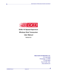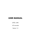
1
USER MANUAL
SATEL i-LINK
I/O-converter
Version 1.4
SATEL i-LINK
User Manual, Version 1.4
TABLE OF CONTENTS
TABLE OF CONTENTS ............................................................................... 2
IMPORTANT NOTICE ................................................................................ 3
PRODUCT CONFORMITY .......................................................................... 4
WARRANTY AND SAFETY INSTRUCTIONS ..................................................... 5
1 GENERAL ............................................................................................. 6
1.1
SATEL I -LINK P ULSE C OUNTER
AND
I/O - CONVERTER .................................. 6
2
SPECIFICATIONS ................................................................................ 7
3
FUNCTIONS ...................................................................................... 8
S CREW CONNECTOR FUNCTIONS .................................................................... 8
3.1 S UPPLY V OLTAGE , 9 – 30 V DC ............................................................. 8
3.2 A LARM OUTPUT , AL OUT .................................................................... 8
3.3 + OUT ........................................................................................ 8
3.4 D IGITAL I NPUTS , I1, I2, AND O UTPUTS O1, O2 ......................................... 8
3.5 P ULSE I NPUT ................................................................................... 8
3.6 I NDICATORS ................................................................................... 8
3.7 DIP-S WITHCES ................................................................................ 9
3.7.1 DIP -switches, 8 pcs ............................................................................................... 9
3.7.2 Address selection table .......................................................................................... 9
3.7.3 Channel selection table ......................................................................................... 9
4
OPERATION ..................................................................................... 11
4.1 P OINT - TO -P OINT ........................................................................... 11
4.1.1 Updating Digital messages .................................................................................. 11
4.1.2 Start of the Point-to-Point operation ...................................................................... 11
4.2 P OINT - TO -M ULTIPOINT ..................................................................... 11
4.2.1 Start of the Multipoint operation ........................................................................... 11
5
FACTORY SETTINGS .......................................................................... 12
6
CONNECTION EXAMPLES ................................................................... 13
7
ACCESSORIES ................................................................................... 14
2
SATEL i-LINK
User Manual, Version 1.4
IMPORTANT NOTICE
All rights to this manual are owned solely by SATEL OY (later called also SATEL). All rights
reserved. The copying of this manual without the written permission from the owner of the rights by
printing, copying, recording or by any other means or the full or partial translation of the manual
to any other language including all programming languages using any electrical, mechanical,
magnetic, optical, manual or other methods or devices is forbidden.
SATEL reserves the right to change the technical specifications or functions of its products or to
discontinue the manufacture of any of its products or to discontinue the support of any of its
products without any written announcement and urges its customers to ensure, that the information
at their disposal is valid.
SATEL software and programs are delivered ”as is”. The manufacturer does not grant any kind of
warranty including guarantees on saleability and guarantees pertaining to applicability to a certain
application. Under no circumstances is the manufacturer or the developer of a program
responsible for any possible damages caused by the use of a program. The names of the
programs as well as all copyrights relating to the programs are the sole property of SATEL. Any
transfer, licensing to a third party, leasing, renting, transportation, copying, editing, translating,
modifying into another programming language or reverse engineering for any intent is forbidden
without the written consent of SATEL.
SATEL PRODUCTS HAVE NOT BEEN DESIGNED, INTENDED NOR INSPECTED TO
BE USED IN ANY LIFE SUPPORT RELATED DEVICE OR SYSTEM RELATED
FUNCTION NOR AS A PART OF ANY OTHER CRITICAL SYSTEM AND ARE
GRANTED NO FUNCTIONAL WARRANTY IF THEY ARE USED IN ANY OF THE
APPLICATIONS MENTIONED.
3
SATEL i-LINK
User Manual, Version 1.4
PRODUCT CONFORMITY
SATEL i-LINK
Hereby, SATEL Oy declares that SATEL i-LINK converters are in compliance with the essential
requirements and other relevant provisions of Directive 89/336/EEC. Therefore the equipment is
labelled with the following CE-marking.
0523
4
SATEL i-LINK
User Manual, Version 1.4
WARRANTY AND SAFETY INSTRUCTIONS
Read these safety instructions carefully before using the product:
Warranty will be void, if the product is used in any way, which is in contradiction with the
instructions given in this manual, or if the housing of the radio modem has been opened or
tampered with.
The radio modem is to be used only on frequencies allocated by local authorities and without
exceeding the given maximum allowed output power ratings. SATEL is not responsible, if any
products manufactured by it are used in unlawful ways.
The devices mentioned in this manual are to be used only according to the instructions described
in this manual. Faultless and safe operation of the devices can be guaranteed only if the transport,
storage, operation and handling of the devices are appropriate. This also applies to the
maintenance of the products.
To prevent damage both the radio modem and any terminal devices must always be switched
OFF before connecting or disconnecting the serial connection cable. It should be ascertained that
different devices used have the same ground potential. Before connecting any power cables the
output voltage of the power supply should be checked.
Salo, Finland 2012
5
SATEL i-LINK
User Manual, Version 1.4
1 GENERAL
1.1 SATEL i- LINK Pulse Counter and I/O - converter
The SATEL i-LINK is a Point-to-Point or Point-to-Multipoint transparent I/O-converter with a pulse
counter input. The device works together with SATELLINE-1870, -1870E and -1915 radio
modems. In Point-to Point transmission the digital status information can be sent through the radio
modem to output in the other end. In Point-to-Multipoint mode it is also possible to read
information from pulse transponders. Point-to-Multipoint transmission is possible adopting software
suitable for the SATEL i-LINK.
Screw connectors from left to right
1 = minus
3 = 9-30 VDC / - +
4 = + OUT
5 = AL OUT
6, 7 = I1, I2
8 = 10 kHz
9 -12 = O1, O2
Indicators
ON
ALARM
I1, I2
O1, O2
P1
DIP-Switches 8 pcs
1 PRTCL, Protocol
2, 3, 4, 5 / P-to-P
2, 3, 4, 5 / P-to-MP
6
7 DE
8 SM
6
i-LINK ground
Supply Voltage
+ out for other devices
Alarm output
Digital inputs
Pulse Input
Digital outputs from internal
relay contacts
Power ON/OFF
Failure in transmission/device
Digital inputs
Digital outputs
Pulse counter input
0=P-to-P, 1=Point-to-Multipoint
ADDRESS. Max 15.
CHANNEL. 10 channels.
Transmission cycle
0= once/ second (by European
standard)
1= 3 times/second
Alarm Delay. 1=ON. 0= OFF
Safe Mode. 1=ON. 0= OFF
SATEL i-LINK
User Manual, Version 1.4
2 SPECIFICATIONS
FEATURE
min-max
Supply Voltage
+9...30 Vdc
Power consumption
Serial Interface
Response time
Operational temperature
Transfer rate
0.03...0.1 VA
RS-232 ± 15 Vdc
< 250 ms
-25…+55 oC
9600 bps
PULSE COUNTER
Inputs, 1 pc
Minimum pulse width
max. 10 kHz
5 µs
DIGITAL SIGNALS
Inputs, 2 pcs
Outputs, 2 pcs
0 – 35 Vdc
0 – 30 V DC/AC/1 A
INDICATORS
Indicators
Power ON/OFF, Digital IN/OUT, Alarm, Pulse IN.
OTHER OUTPUTS
Alarm Output
+9 – 35 Vdc / 30 mA
GENERAL
Housing
Connectors
Size L x W x H
Weight
Mounting
IP
Modem compatibility
typical
note
Supply Voltage to
i-LINK regulated by the
radio modem
(5.3 Vdc)
40 mA @ 12Vdc
± 6 Vdc
< 300 ms
0 – 30 Vdc
Metal plate, painted
16 pins for radio modem
12 pins for other connections
123 x 85 x 30 mm
80 g
Wall plate
IP-20
SATELLINE-1870, -1870E, -1915
7
active RS-232
@ 9600 bps
resistive 4-5 kΩ,
relay contacts (normal= open)
Alarm= + supply voltage
drive current 30 mA.
SATEL i-LINK
User Manual, Version 1.4
3 FUNCTIONS
Screw connector functions
3.1 Supply Voltage, 9 – 30 Vdc
o The minus contacts are in parallel. One is for the i-LINK and another can be used for
external devices and connections. Plus (+) is for supply voltage.
3.2 Alarm output, AL OUT
o The AL OUT is activated, when three transmission fails has occurred one after another.
When activated the AL OUT goes to +VDC. Driving current is max. 30 mA.
3.3 + OUT
o + OUT is internally connected to + VDC through an automatic fuse. The supply voltage
for other devices.
o Connections can be taken from the +OUT.
3.4 Digital Inputs, I1, I2, and Outputs O1, O2
o Inputs,
o 2 pcs. Activated with + VDC. A transmission is made always when there is a
change in the input (P-to-P). Minimum Voltage for “1”-state triggering is 7 Vdc.
o
Outputs,
o 2 pcs. Open relay contacts. Max. rating 9 – 30 VDC / AC / 1 A load.
3.5 Pulse Input
Can be used only in Point-to-Multipoint mode.
o For fast pulses. Maximum frequency is 10 kHz.
3.6 Indicators
o ON
o Power ON/ OFF. Illuminated when +VCD is connected. Blinking, if the device is
not working.
o
O1…O2, PO… PO1
o Showing the status of the input and output. Illuminated when the consequently pin is
activated.
o
ALARM
o Illuminated, if a fail in transmission has occurred. If the i-LINK has not received
confirmation to the sent message, it will repeat the transmission. Three fails in turn
switches the AL OUT and the alarm LED ON.
o
I1…I2, PI1…PI2
o Showing the status of the Input. Illuminated when the consequently pin is activated.
8
SATEL i-LINK
User Manual, Version 1.4
3.7 DIP- Swithces
3.7.1 DIP -switches, 8 pcs
1 MP, Protocol-switch
1= M, for Point-to-Multipoint (Master-Slave) -operation
0= P, for Point-to-Point -operation
Point-to-Multipoint operation mode
2, 3, 4, 5, ADDRESS
Used in Point-to-Multipoint -operation to set channel for the sub-station.
Maximum number of addresses is 15.
3.7.2 Address selection table
DIP 2 3 4 5
0 0 0 0= reserved for the Main Station
0 1 0 0= address 2
0 0 1 0= address 4
0 1 1 0= address 6
0 0 0 1= address 8
0 1 0 1= address10
0 0 1 1= address 12
0 1 1 1= address 14
DIP 2 3 4 5
1 0 0 0= address 1
1 1 0 0= address 3
1 0 1 0= address 5
1 1 1 0= address 7
1 0 0 1= address 9
1 1 0 1= address 11
1 0 1 1= address 13
1 1 1 1= address 15
Point-to-Point operation mode
2, 3, 4, 5 CHANNEL
Used in Point-to-Point-operation to select / change the operational channel.
When the power is turned ON, the i-LINK reads the channel information from the DIP switches. Default mode setting is 0-0-0-0, 1=up / 0=down.
The channel can be changed by turning first the power OFF and then by setting the DIP switches (channel selector) to selected channel position for example 1-0-0-0.
3.7.3 Channel selection table
DIP 2 3 4 5
0 0 0 0=disable (channel selection is not in use)
0 0 1 0=ch 2
0 1 0 0=ch 4
0 1 1 0=ch 6
1 0 0 0=ch 8
1 0 1 0=ch10
9
0 0 0 1=ch 1
0 0 1 1=ch 3
0 1 0 1=ch 5
0 1 1 1=ch 7
1 0 0 1=ch 9
SATEL i-LINK
User Manual, Version 1.4
NOTE1!
Check, that both i-LINKs are set to the same channel before turning the power ON.
New channel is activated when the power is turned ON.
NOTE2! The i-LINK unit will not operate with these settings:
1011, 1100, 1101, 1110 or 1111. The power ON indicator starts to blink in case any of these
settings has been chosen.
ADDRESS/ CHANNEL/DE-SM
7 DE
Delayed alarm
o Immediate / Delayed Alarm
In case of a failure in the transmission, the alarm output response can be selected from
immediate alarm to 10 seconds delayed alarm.
8 SM Safe Mode
o Unchanged output state / Safe Mode state
In case a failure in transmission, the outputs can be set to remain their status (unchanged)
or change to “Safe Mode” which will switch all outputs to OFF-position. Safe Mode timing
follows the setting of the switch 7 DE, so it can be immediate or delayed by 10 seconds.
Selection table of the Dip–switches 7 and 8
7DE 8SM
0
0 = Immediate Alarm / No Safe Mode
0
1 = Immediate Alarm / Immediate Safe Mode
1
0 = Alarm delayed by 10 seconds / No Safe Mode
1
1 = Alarm delayed by 10 seconds / Safe Mode delayed by 10 seconds
6 Selecting of the transmission standard
According to the European standard for free channel operation, the ratio of the
transmission cycle must not be more than 10/90. This is active when the DIP-switch
number 6 is 0. In position 1 the cycle is faster.
Selection table of the DIP-switch number 6
0= one transmission cycle per second
1= 3 transmission cycles per second.
10
SATEL i-LINK
User Manual, Version 1.4
4 OPERATION
The Operation mode is selected using the PRTCL-switch. The operations are Point-to-Point or
Point-to-Multipoint. In Point-to-Point operation mode the system consists of one pair of units. The
inputs of the unit are transmitted as outputs of the other unit.
In Multipoint mode the main-station controls the sub-stations.
4.1 Point- to- Point
Point-to-Point operation is between two units. The inputs of the unit are transmitted as outputs of
the other unit.
4.1.1 Updating Digital messages
Digital information (relay, switch etc.) will be sent to the other unit always, when there is a
change at the input.
4.1.2 Start of the Point-to-Point operation
o Connect radio modem to i-LINK directly to its connector and check that
it is locked.
o The MP-switch must be “0 ”, in the P-to-P-position.
o Before connecting the device to a power supply, connect first all inputs
and outputs that are to be used.
o When both units have these basic settings the supply voltage can be connected.
o Check that the channel switches 2, 3, 4, 5 = 0000, unless they are
purposely selected for a specific channel for example 2, 3, 4, 5= 0101=
channel 5 (see chapter 3.7… /channel selection table).
4.2 Point- to- Multipoint
In this mode the program at the main station controls the units of the sub stations. The main
station can drive one or more sub stations (maximum 15 pcs / system).
4.2.1 Start of the Multipoint operation
o
Connect one SATELLINE radio modem to the COM-Port of the PC.
o
Connect the i-LINK slave(s) to the radio modems.
o
The “MP”- switch must be “1”, in the P-to-MP-position.
o Before connecting the device to a power supply, connect first all inputs and outputs that are
to be used.
o Set individual address to all slaves. (As this is a master–slave operation, the slaves have
to be addressed). All slaves must have different address (see chapter 3.7…/address
selection table.
o Start using the system by the master by opening the controlling program for example
SATELLINK PC Pro etc.
o
With the program it is possible to turn ON / OFF the outputs and monitor the inputs.
Please contact local SATEL distributor or visit SATEL’s web site in order to get information of the
multipoint commands.
11
SATEL i-LINK
User Manual, Version 1.4
5 FACTORY SETTINGS
The i-LINK I/O -converter is shipped with the following default settings (unless specifically ordered
with settings other than those listed below):
FIXED SETTINGS DEFINED AT THE TIME OF ORDER
PM, protocol switch, P-to-P or Multipoint
ADDRESS/CHANNEL
Transmission cycle
DE, Alarm delay
SM, Safe mode
0
0000
0
0
0
12
= Point-to-Point
= No address
= 1/sec (European std.)
= No Delay
= No Safe Mode
SATEL i-LINK
User Manual, Version 1.4
6 CONNECTION EXAMPLES
Point-to-Multipoint
Point-to-Point
13
SATEL i-LINK
User Manual, Version 1.4
7 ACCESSORIES
SATELLINK PC and SATELLINK PC Pro
Programs that make it possible to operate a Multipoint system with a PC.
Layout of the SATELLINK PC Pro Multipoint-program
14