1
Hall Research Technologies, Inc
Phone:
Fax:
1163 Warner Ave.
Tustin, CA 92780
(714) 641-6607
(714) 641-6698
User’s Manual
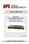
Model MC1208
8-channel KVM switch with OSD & 1RU Kit
Control 8 PC's from one
monitor, keyboard and mouse
May, 2007
UMA1104 Rev. 1
Table of Contents
INTRODUCTION
2
GENERAL
SUPPORTED SYSTEMS AND PERIPHERALS
2
2
FEATURES
2
SETUP
2
OPERATION
3
FRONT PANEL INDICATORS
SWITCHING
3
3
ON SCREEN DISPLAY
3
-1-
Introduction
MC1208 allows 1 monitors, 1 keyboard, and 1 mouse to control 8 different PC’s or servers. By chaining more of these
units up to 128 PCs can be controlled from one user station.
FIGURE 1 Connector Functions on Rear Panel
General
The MC1208 displays the selected PC’s video at full resolution using wideband video circuits. It also routes the signals
from the mouse and keyboard to the selected pc. The unit includes brackets for rack installing (as a 1 RU).
Supported Systems and Peripherals
•
•
•
•
All PC compatible systems and notebooks
Standard PS/2 and AT Keyboards (Legacy AT keyboards may require connector adapters)
Standard (2-button) and wheel (3-button) (e.g. Microsoft Intellimouse) mice. 4-button mice are not supported.
VGA, XGA, UXGA video resolutions to 1600x1200 at 50 to 85 Hz refresh rate.
Features
•
•
•
•
•
•
•
•
•
Slim 1 RU construction.
Built-in power supply (no external brick needed)
Reliable operation
Quick and easy switching between PC’s
LED indicators of PC power status and PC selected
Only one cable needed to connect to each PC
Supports Hot-plug – simulates mouse and keyboards for all pcs
Individual front panel switches for Selecting PCs
Hot-key PC selection from the keyboard
Setup
FIGURE 2 CW-1208-10 Cable for connection to each PC
-2-
1. Start with the PCs turned off, then use the 3-in-1 cable (part # CW-1208-10) to connect each PC to the MC1208. This
cable is 10 ft long and is sold separately.
2.
Connect your console (keyboard, mouse, and monitor) to the MC1208.
3.
Plug in the power supply cord comes with the MC1208 to the unit and connect it to an AC outlet and turn the switch
on the rear of the unit to ON
4.
Turn the PC’s on
5.
The keyboard and mouse may now be treated as a keyboard and mouse connected directly to the PC that is selected
through the unit.
Operation
The keyboard and mouse will function no differently than if the keyboard and mouse were connected directly to the PC.
Front panel indicators
The front panel has LEDs indicate which PCs are connected and powered up and which one is selected.
Online : A green light indicates that the PC or KVM connected to the corresponding port is on and operating
Selected : A red light indicates the situation of being connected to the port .
There is also a Blue Power on LED
Switching
There are two ways to switch to among PCs.
The first way is to simply press the button for the desired PC on the front panel of the MC1208. You can not switch to a
PC that is not connected or turned off.
The front panel can also be used to do the following:
Simultaneously press Push Buttons 1 and 2 to directly enter the OSD Control Mode
Simultaneously press Push Buttons 7 and 8 to activate “Console-Reconfirmed”. If you have attached a new
mouse or keyboard or monitor, their ID information and characteristics will be read and stored for the connected
PCs
The second way to switch is through a hot-key combination from the keyboard either by going to next PC or by invoking
the OSD and selecting a PC.
If the SVS (Smart View Setting) mode is enabled (through OSD), the hot-key combination for selecting the Next PC is
simply hitting the Ctrl key twice.
Alternatively, press the Numlock on the keyboard twice. To activate the OSD.
Use the UP, Down and Enter keys on the keyboard to switch or move the mouse to the target PC , and then double click
the left button.
Additionally , you also can use the numeric keys to enter the direct switch. For example , if you want to switch to port 4
of a Slave KVM that is connected to Master KVM port 03 , then you can start the OSD and then directly enter 0304 . If
thee is no slave KVM connected, then just enter the first two digits of the port. More on Master, Slave later.
On Screen Display
Activation
Press the NumLock twice or the Port Selection Switches 1 and 2 on the front panel to enter the OSD .
Note :
-3-
If you have modified the Hot Key for starting the OSD and are unable to enter the OSD by pressing NumLock , then you can
start the OSD by using the Port Selection Switch first , and then press F9 to enter into the System Setting to modify the options of
the OSD Entry Hot Key .
Operation
You can operate the OSD by keyboard or mouse. For keyboard operation , besides the common Up and
Down keys , there are special Function keys such as Enter , Space Bar , Function Key (F1,F4…) under the OSD
remark field . For the mouse operation , the left key refers to Enter and the right key refers to Exit . For example ,
move the mouse point to your desired PC , and click the left key . The selection bar will move to that position and
then click the left key again for the execution .
Note :
You must use the keyboard to complete the two functions : Name Edit and Password
OSD Switch Menu
1. This field provides the information of the currently connected PC. As shown in the figure above 03, refers to the Port Number
or the Master ;04 refers the Port Number of the Slave ; and Mail Ser 4 is the name of this PC defined by the user. If a PC
-4-
connects to the Master , then the number consists of the first two digits , If you have not given a name for the PC, the name field
will be blank.
2. This field shows the list of the Master KVM or a certain set of Slave KVM currently displayed on the OSD . We
recommend you to give a name to the Slave KVM , or else the display after LIST : will be blank .
3. This field shows the list of connections to the KVM , and the fields are described below :
PWR : It shows the status of power of the PC (or slave unit) connected to the CPU port on the rear of the unit.
C# : It shows the channel number
KVM : If a slave is connected at this input, it shows the KVM capacity of the Slave unit
NAME : It shows the name of the equipment , and users can name the Slave KVM or PC on their own . There are
a total of 12 characters Selected from the group of “A~Z”,”a~z”,”0~9”,”+”,”-“,”*”,”/”,”=”,”[“,”]” “,” , “’” , “, “ , “.” ,
“, “ , “:” .
Note : Please use the CapsLock to toggle the upper and lower cases .
SVS : It shows the Smart View Setting ; use + to open and - to close. The SVS is blank and not clickable if the KVM is
connected as slave . If SVS is selected , then you can switch by the Hot Key Switch or Mouse Clicking or selecting the option by
Auto Scan . You also can use mouse to click this field .
System Setting Menu
Channel Display Mode :
Channel Display Time :
Auto Scan Time :
OSD Entry Hot Key :
Hot Key Switching :
Mouse Clicking :
Beeper Sound :
Offline Skip :
OSD Language :
Security Level :
Console Lock Time :
Full
5 Sec
5 Sec
Number Lock
OFF
OFF
ON
Manual
English
None
5 Min
F1 : Information ; It provides the model name and F/W version information
-5-
F4 : OSD Position ; You can enter the OSD position to make adjustments; We recommend
you to use the same the resolution for all computer displays, and use this function again to
adjust the OSD position , You Can use the Up, Down ,Left or Right keys on the keyboard or a
mouse to move.
F8 Restore Default Settings.
Auto Scan Mode: Activate the OSD and press F4. . Use the ESC key to exit Auto Scan.
Security Mode: It is best to leave the security to “none” as there is a danger of not being able to use the unit.
-6-
© Copyright 2007. Hall Research Technologies, Inc.
All rights reserved.
..
..
..
..
Hall Research Technologies, Inc.
1163 Warner Ave.
Tustin, CA 92780
Phone: (714) 641-6607
Fax:(714) 641-6698
-7-