1
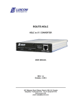
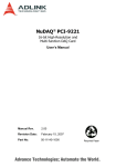
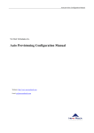
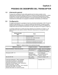
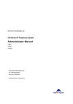
EM2-VR
One channel Voice / Data combiner
E&M Voice + RS232 Data to E0/DS0
EM200-VR
Thirty channel Voice / Data Combiner
E&M Voice + RS232 Data to E1
USER MANUAL
Rev. 1.2
December 20, 2011
102 WALGREEN ROAD, OTTAWA, ONTARIO, K0A 1L0
Telephone (613) 831-7777 Fax (613) 831-7778
www. luxcom.com
email: [email protected]
Table of Contents
Introduction...........................................................................................................1
EM2-VR (one channel voice/data combiner)......................................................2
Description...............................................................................................................2
Voice Port..................................................................................................................2
RS232 Port................................................................................................................3
WAN Port (E0/DS0)...................................................................................................4
Power Input...............................................................................................................5
Alarm Closure Contacts..........................................................................................5
Indicators..................................................................................................................5
Console Port.............................................................................................................6
Console Port Setup........................................................................................6
Console Port Menus.......................................................................................6
User Configurable Options.....................................................................................7
RS232 Local Loop Back test..........................................................................7
RS232 Remote Loop Back test......................................................................7
RS232 + Voice V.35 Loop Back test..............................................................7
Audio gain.......................................................................................................7
Set 2-wire or 4-wire audio mode...................................................................7
E&M Signalling................................................................................................8
EM2-VR Mounting Base .........................................................................................8
EM200-VR (thirty channel voice/data combiner)................................................9
Description...............................................................................................................9
Chassis 16-Slot .......................................................................................................9
Power Supplies.............................................................................................10
Indicators.......................................................................................................10
Rack Mounting..............................................................................................10
E1 Line Interface Card (EM200-E1).......................................................................11
Indicators.......................................................................................................11
Channel Mapping..........................................................................................11
Specifications* .............................................................................................11
DC-DC Power Supply*..................................................................................11
Console Port Menus ....................................................................................12
Voice/Data Interface Card (EM200-VR).................................................................13
Indicators ......................................................................................................13
Monitor Port Menu.......................................................................................13
Ordering Information..........................................................................................14
Certification.........................................................................................................14
Warranty..............................................................................................................14
I
II
Manual Revision History
R1.0 Initial release June 25, 2011
R1.1 Cosmetic October 13, 2011
R1.2 Added alarm contact closure December 13, 2011
III
Introduction
The first section of this manual describes the EM2-VR one channel voice/data combiner, and
the second section describes the EM200-VR 30 channel voice/data multiplexer.
The EM2-VR combines a bi-directional 2-wire or 4-wire voice signal with a full duplex RS232
data channel, and transmits it over a 64 kbps synchronous E0 or DS0 channel with a V.35
interface. At the remote end which may be another EM2-VR or an EM200-VR, these
combined data/voice signals are separated, and output on their respective connectors. Note
that when using a DS0 channel in a T1 carrier, there must be no “robbed bits”. The voice
channel supports E&M signalling and a high quality voice which is compressed to 40 kbps.
The RS232 channel is data format and speed transparent to rates of 19.2, 9.6, 4.8, 2.4,
and1.2 Kbps and less.
An EM2-VR back to back connection is shown below.
EM2-VR
VOICE
EM2-VR
Telco Network
DS0 V.35
MODEM
RS232
DS0 V.35
MODEM
RS232
VOICE
EM2-VR back to back connection
The telephone company (which supplies the E0 channels) may combine up to 30 of the EM2VR data streams into a single higher speed E1 signal. Luxcom's EM200 multiplexer
interfaces to this line, demultiplexes the voice/data channels and outputs them on the EM200VR cards in their original form. This EM200 multiplexer is a 3U, 19” rack mountable chassis
which holds one E1 transceiver card (EM200-E1), and up to 15 dual channel Voice/Data
cards (EM200-VR). This topology is shown below.
LUXCOM'S EM200 MULTIPLEXER 16 SLOT CHASSIS
EM2-VR
RS232
VOICE
EM200-E1
DS0 V.35
MODEM
E1 IN
EM200-VR
EM200-VR
EM200-VR
EM200-VR
RS232 A
RS232 A
RS232 A
RS232 A
VOICE A
VOICE A
VOICE A
VOICE A
RS232 B
RS232 B
RS232 B
RS232 B
VOICE B
VOICE B
VOICE B
VOICE B
Up to 15
EM200-VRs
E1 OUT
Up to 30
EM2-VR
EM2-VR
RS232
VOICE
Telco E1 Mux
DS0 V.35
MODEM
EM2-VR to EM200 connection
Features
High quality Voice plus RS232 data over one E0/DS0 channel
Transparent to standard RS232 rates
USB configuration port shows network-wide status
Industrial temperature -40°C to 70°C
5 Year warranty
EM2-VR voice/data modem
EM200 30 channel voice/data mux
2-Wire or 4-Wire voice
Back to back operation
Isolated 48VDC power input
30 voice/data channels in a 3U 19” rack
Redundant power supply available
An E1 line cost much less than 30 E0 lines
1
EM2-VR (one channel voice/data combiner)
Description
A block diagram of the EM2-VR modem is shown below.
Voice Port
This RJ45 connector has the voice and E&M signalling. One end of a standard
Ethernet cable may be used to connect to this port; the other end of the cable
will need to be customized to interface to the attached equipment. The tip/ring
wires for the audio connection can be reversed without affecting performance.
The pin assignments are shown in the following table.
Pin #
1
2
3
4
5
6
7
8
Name
SB
M
R2
R1
T1
T2
E
SG
Function
Send Battery
M lead
RING 2
RING 1
TIP 1
TIP 2
E lead
Signal Ground
PIN1
E&M Signal
-24V Output used for M-lead signaling
Input
Input in 4-Wire mode, unused in 2-Wire mode
Output in 4-Wire mode, Bidirectional in 2-Wire mode
Output in 4-Wire mode, Bidirectional in 2-Wire mode
Input in 4-Wire mode, unused in 2-Wire mode
Output
Common * Note 1
*Note 1: Historically, earth ground was the return path for E&M signalling; the return path for
the EM2-VR is the Signal Ground pin; therefore it should be connected to the signalling
ground of the attached equipment.
2
Specifications*
Number of audio channels ............................................ 1
Input/Output connectors................................................. RJ-45
Input/Output impedance................................................. 600 ohms nominal
Analog bandwidth........................................................... 200 Hz to 3.4 kHz
Analog input Level without significant distortion.............. 7 Vpp
Analog insertion gain adjustable..................................... 0, +/-1, +/-2, +/-3 dB
Encoding......................................................................... 5 bit ADPCM
Idle channel noise (C Message Weighted)..................... < 20 dBrnC
Idle channel noise (3 kHz flat)........................................ < 27 dBrn
Tip/Ring DC voltage........................................................ 0V
*Specifications subject to change without notice
RS232 Port
This RJ45 connector has a standard EIA/TIA 561 DCE RS232 interface. This full duplex
asynchronous channel supports data rates of 19.2, 9.6, 4.8, 2.4, and 1.2 Kbps or less. There
are no user settings for data rate or the number of bits per character. Request to Send is
sent across the link, and is output as CTS at the remote end. Local and Remote Loopback
may be initiated from the USB configuration port for the purpose of testing the link.
A DCE usually Interfaces with a DTE, so a straight through Ethernet cable can be used.
Pin assignments are shown below.
PIN1
Pin #
1
2
3
4
5
6
7
8
DSR
DCD
DTR
GND
RXD
TXD
CTS
RTS
Pin Name
Data Set Ready (optional)
Data Carrier Detect
Data Terminal Ready
Ground
Receive Data
Transmit Data
Clear To Send
Request to Send
3
Direction
Output always Hi
Output always Hi
Input (not used)
Output
Input
Output
Input
WAN Port (E0/DS0)
The DB-25P connector connects to the 64 kbps E0/DS0 telephony modem. The EM2-VR
usually transmits and receives based on the S-CLK; in its absence it uses RXC.
The +/- phases of the balanced inputs/outputs must share the same twisted pair conductor;
otherwise cross talk will interfere with transmission. Unbalanced lines such as RTS can share
a twisted pair conductors. An external overall shield is recommended to minimize RF
radiation; this shield should be connected to pin 1 (chassis ground) of the EM2-VR DB25S
connector. A typical cable is 24AWG with 100 to 120 Ohms characteristic impedance. Signal
ground (DB25 pin 7) must be connected. Stranded rather that solid conductors are best.
The pinout for a V.35 M34 connector to DB25 connector is shown below.
V.35 M34
V.35 DB-25
NAME
DESCRIPTION
A
B
A
B
A
FG
Frame Ground
1
B
SG
Signal Ground
7
P
S
SD
Send Data
2
14
R
T
RD
Receive Data
3
16
C
RTS
Request to Send
4
D
CTS
Clear to Send
5
E
DSR
Data Set Ready
6
H
DTR
Data Terminal Ready
20
F
RLSD
Receive Line Signal Detect
8
U
W
SCTE
Serial Clock Transmit (External)
24
11
Y
AA
SCT
Serial Clock Transmit
15
12
V
X
SCR
Serial Clock Receive
17
9
L
Local Loopback
18
N
Remote Loopback
21
M
LT
Test Mode
4
25
Power Input
The nominal 48 Volt power input accepts voltages between 36 and 62 VDC. This input is
isolated from signal and chassis ground. The center pin must be positive. If an AC-DC
power cube is required, a 100-240 VAC, 50-60Hz input to 48 VDC out power cube is
available as a separate order - part number 83-053-0.
Alarm Closure Contacts
The removable two pin screw terminal block connects to isolated, non-polarized dry contacts.
These contacts close when either the EM2-VR loses power or the LINK with the remote end
is lost.
Max voltage= 60 Vpeak
Max current = 150 mA.
Max resistance = 16 Ohms.
Indicators
The front panel indicators are as follows:
POWER
On when the unit has POWER.
LINK
On when the modem is linked with the remote interface.
RS232-IN
On when data transitions are detected on the RS232 input.
RS232-OUT
On when data transitions are detected on the RS232 output.
M-IN
On when an off-hook is detected on the input M lead of the E&M line.
E-OUT
On when an off-hook is being output on the E lead of the E&M line.
VOICE-OL
On when the input voice signal is too high (Over Load). The voice
signal may be lowered using the configuration interface.
5
Console Port
The console port is used to check the link status, as well as to set various operating
parameters. The port is a standard mini-B USB 2.0. A USB cable is supplied. See the
Console Port Setup section.
Console Port Setup
On the EM2-VR modem a USB 2.0 mini-B connection monitors status and sets the
operating parameters. A USB cable is supplied for this purpose. The following steps
access the configuration menu.
1. Connect the USB cable from the EM2 to the PC. Windows TM will search online
for the driver, find it, and install it. If this step fails you can download the driver
from http://www.ftdichip.com/Drivers/VCP.htm.
2. Now find which Com port is connected to the USB driver. Go to the START
menu (Win 7); click on Devices and Printers; click on USB <-> Serial Cable;
select Hardware; see which COM port is used, ex: (COM6).
3. Activate HyperTerminalTM (or another terminal emulation program such as Tera
TermTM) enter the Com port number.
4. Configure HyperTerminalTM 1as follows:
Baud Rate = 38400; Data = 8 bits; Parity = none; Stop = 1 bit; Flow control =
none.
5. Hit the ESC key a few times until the Main Menu displays.
Console Port Menus
1
2
3
4
Show local menu
1 Show status
2 Options menu
1 Set signalling type
2 Set audio gain
3 Set 2-wire or 4-wire audio mode
4 Name modem
3 Firmware upload menu
4 Software upload menu
5 Reset modem
Show remote menu
1 Show status
2 Options menu
1 Set signalling type
2 Set audio gain
3 Set 2-wire or 4-wire audio mode
4 Name modem
3 Firmware upload menu
4 Software upload menu
5 Reset modem
Show test menu
1 Enable RS232 local loopback
2 Enable RS232 remote loopback
3 Enable V.35 local loopback
Set password
(default password is luxcom)
6
User Configurable Options
RS232 Local Loop Back test
Input data is looped to output for testing of local connection. This tests the RS232 cable
integrity. An external E0 connection is not necessary for this test. Be sure to disable
loop-backs once the test is finished.
RS232 Remote Loop Back test
Input data travels to remote modem where it is sent back and output. It tests the total link
except the remote cable. Be sure to disable loop-backs once the test is finished.
RS232 + Voice V.35 Loop Back test
Puts the LLB line high (pin 18) on the attached E0 modem requesting it to loop-back its data
for testing of the local connection. Note that some E0 modems will not respond to this signal
line. Be sure to disable loop-backs once the test is finished.
Audio gain
Set gain for audio input (voice channel) to 0, +/-1, +/-2, +/-3 dB. The card is shipped with 0
dB (unity) gain, and should only be adjusted if problems arise. Average audio signals are
usually about 0.7 Vpp (-10 dBm) with peak levels up to 7 Vpp; this modem will to accept
these levels without distortion. If the input audio is significantly lower, the output signal will
be too quiet. If the input audio is too high, the output signal will distort. The Audio Overload
LED will flash if the input voice is too high. In two wire mode Audio gain cannot be set
above 0 dB.
Set 2-wire or 4-wire audio mode
If the interface attached to the E&M card has only two wires for the audio, select TwoWire mode. If the interface has separate transmit /receive pairs, select Four-Wire
mode. Four-Wire mode is the default factory setting.
7
E&M Signalling
The EM2-VR E&M interface is line side equipment which connects to a PBX (Private
Branch Exchange). E&M signaling Types 1 to 5 are supported. North America and
Japan normally uses Type1 signaling, while Type 4 signaling is common in the rest of
the world. The EM2-VR is line-side equipment, so be sure the PBX is set to act as
Trunk side equipment. The signaling type is set using the USB configuration port. The
signaling types are shown in the following figures.
Trunk Side
PBX
-48V Detect
-48V
Off-Hook
TYPE I
Line Side
2 or 4 Wire Audio
EM2-VR
E
7
SG
8
M
2
1
Trunk Side
PBX
-48V Detect
Off-Hook
TYPE II
From Remote
end
Off-Hook
Detect
To Remote
end
To V.35 Modem
Line Side
2 or 4 Wire Audio
EM2-VR
E
7
SG
8
M
2
SB
1
From Remote
end
Off-Hook
Detect
To Remote
end
To V.35 Modem
-24V
Trunk Side
PBX
-48V Detect
Off-Hook
Trunk Side
PBX
-48V Detect
Off-Hook
Trunk Side
PBX
-48V Detect
Off-Hook
TYPE III
Line Side
2 or 4 Wire Audio
EM2-VR
E
7
SG
8
M
2
SB
1
From Remote
end
Off-Hook
Detect
To Remote
end
To V.35 Modem
-24V
TYPE IV
Line Side
2 or 4 Wire Audio
EM2-VR
E
7
SG
8
M
2
SG
1
TYPE V
Off-Hook
Detect
To Remote
end
To V.35 Modem
-24V
Line Side
2 or 4 Wire Audio
EM2-VR
E
7
SG
8
M
From Remote
end
2
1
From Remote
end
Off-Hook
Detect
To Remote
end
To V.35 Modem
-24V
EM2-VR Mounting Base
This mounting bracket is screwed to a flat surface and the EM2-VR clips into it. This bracket
is a separate order. Part Number: MB05
8
EM200-VR (thirty channel voice/data combiner)
Description
The E0/DS0 data channels from up to 30 EM2-VR field units may be combined by the Telco
into one E1 signal. This E1 signal can interface with Luxcom's EM200 chassis where it is
demultiplexed into separate voice/data I/Os. The advantages of this topology (over separate
back to back EM2-VRs) is that the cost of a single leased E1 line is less than 30 individual E0
lines, the equipment cost is less, and the footprint more compact.
The EM200VR is a rack mounted chassis with 16 I/O slots and 2 power supply slots; shown
in the following diagram. The various parts of the product are described below.
EM200-E1 EM200-VR EM200-VR EM200-VR EM200-VR
1
E1 IN
E1 OUT
RS232 A
RS232 A
RS232 A
RS232 A
VOICE A
VOICE A
VOICE A
VOICE A
2
3
4
Up to 15
EM200-VRs
POWER
POWER
SUPPLY 1 SUPPLY 2
(optional)
5
RS232 B
RS232 B
RS232 B
RS232 B
VOICE B
VOICE B
VOICE B
VOICE B
Block Diagram
Chassis 16-Slot
This chassis has 16 slots. An EM200-E1 card must be installed in slot 1. Slots 2-16 can
hold up to 15 EM200-VR cards. There are two additional slots for plug-in power supplies.
The chassis, interface cards, and power supplies are ordered separately.
Front view
9
Rear view
Dimensions ..........................................................17” x 5.1” x 10.5” (43x13x26 cm)
Weight..................................................................< 6 Kg
Power Supplies
The chassis comes with one or two power supplies. The second optional power supply
is optionally used for redundancy. The supplies may be in either PS1 or PS2 slots. Be
sure the power supply is off (the rack may remain powered) when installing it. Power
supplies are ordered separately from the chassis.
Power supply input..............................................................85 to 264 VAC, 47-63 Hz
Power supply output............................................................ 5 VDC, 6 A max
Additionally the EM200-E1 card comes with a DC input of 5, 12, 24 or 48 volts which
may power the rack fully, or be used in combination with an AC supply for redundancy.
See the EM200-E1/Specification section for ratings.
Indicators
Link:
On indicates synchronization with the E1 signal.
Alarm: On indicates an E1 synchronization or a power supply failure.
Rack Mounting
This 3U high 19” chassis comes with mounting ears which when installed allows direct
mounting in a standard 19” rack. The ears can be mounted on the front or rear,
allowing the multiplexer to face forward or backward.
10
E1 Line Interface Card (EM200-E1)
The EM200-E1 card connects to the E1 line from the Telco. It maps two independent E0
channels to and from each EM200-VR card, as well as combining the EM200-VR outputs into
the E1 output frame.
Indicators
ALARM
On when the card is not in linked with the E1 signal from the
Telco, or the DC power is absent. (see Monitor Port section)
E1 IN
On when in synchronization with the E1 input.
PWR
On when DC power is detected on the Power input.
Channel Mapping
The USB monitor port on the EM200-E1 card will show the mapping between the
EM200-VR slot number and the remote EM2-VR name. It is recommended that all
remote EM2-VRs be given a name using their USB monitor port. The channels are
sequentially mapped to the card slots as shown in the following table.
Chassis slot
2
3
4
5
6
7
8
9
10
11
12
13
14
15
16
Port A E1 time slot
1
3
5
7
9
11
13
15
18
20
22
24
26
28
30
Port B E1 time slot
2
4
6
8
10
12
14
17
19
21
23
25
27
29
31
Specifications*
E1 Line Code ................................................................. HDB3
E1 Data Rate ................................................................. 2048 Kbps
Standards ...................................................................... G.703, G.736, G.775,
Line Impedance ............................................................. Balanced 120 ohm
Operating temperature ................................................... -40ºC to 74ºC
Humidity (RH) ................................................................ 10% to 95% non condensing
DC-DC Power Supply*
The EM200-E1 card comes with a optional DC input of 5, 12, 24 or 48 volts which may
power the rack fully, or be used in combination with an AC supply for redundancy.
Input connector.....................................................................2.1mm barrel jack
Operating temperature..........................................................-25C to 71C
Input power...........................................................................
Input voltage
5 V version............................................4.9 to 5.3 VDC
12 V version..........................................9 to 18 VDC
24 V version..........................................18 to 36 VDC
48 V version..........................................36 to 72 VDC
Output current ......................................................................5 Amps max
** the inputs to the 12V, 24V, and 48V versions are isolated from the internal circuitry.
* Specifications subject to change without notice
11
Console Port Menus
Chassis Level Management Interface
1 Show status
Shows the status and configuration of all cards in the
chassis.
2 Go to EM2-VR card
Once the card (slot) number is entered, the configuration
and status menu for that card becomes available, as shown
in the next table.
3 Local E1 Loopback
E1 output is looped back to E1 input. This tests of most of
the E1 multipexer. It also results in a loopback of all
EM200-VR ports. Data across the E1 link will become idle.
4 Clear E1 Loopback
Terminates the loopback test.
5 Alarm on DC power
Turns the Alarm indicator on when the DC power is absent
on the EM200-E1 card.
6 Alarm off DC power
Alarm indicator is only a function of E1 synchronization.
7 Firmware upload menu
Used only for firmware upgrades. Instructions will be
supplied when necessary.
8 Software upload menu
Used only for software upgrades. Instructions will be
supplied when necessary.
9 Name Chassis
Allows the user to give a name to the chassis which aids in
network management. Must be < 32 characters; spaces
are allowed.
Card Level Management Interface for EM200-VR
1 Show status
Shows the status and configuration of the card.
2 Set Audio gain High.
3 Set Audio gain Normal.
4 Set Audio gain Low
+6 dB gain
Unity gain.
-12 dB gain
5 Set Audio Two-Wire
If the interface attached to the E&M card has only two wires
for the audio, select Two-Wire mode. If the interface has
separate transmit /receive pairs, select Four-Wire mode.
Four-Wire mode is the default factory setting.
6 Set Audio Four-Wire
7 Set E&M Type 1,2,3
8 Set E&M Type 4,5
See the EM2-VR section for more details.
North America uses Type 1 signaling; Type 4 is common in
the rest of the world. Type 4,5 is the default setting.
9 RS232 Local Loopback Input data is looped to output for testing of local connection.
This tests the RS232 cable integrity.
A RS232 Remote Loopback Input data travels to remote modem where it is sent back and
output. It tests the total link except the remote cable.
B Clear all Loopbacks
Terminates all loopback tests.
D Firmware upload menu Used only for firmware upgrades. Instructions will be
supplied if necessary.
E Software upload menu Used only for software upgrades. Instructions will be
supplied if necessary.
F Name Port
Allows the user to give a name to the Port which aids in
network management. Must be < 32 characters; spaces are
allowed
12
Voice/Data Interface Card (EM200-VR)
This interface card has two independent voice/data channels which transmit and receive into
two E0 channels in the E1 frame. Further information on the mapping is found in the E1 Line
Interface Card (EM200-E1) section. Up to 15 of these cards may be installed in a chassis.
The voice and data ports are similar to the EM2-VR ports.
Indicators
ALARM
On when the modem is not linked with the remote interface.
RS232 IN
On when data transitions are detected on the RS232 input.
RS232 OUT
On when data transitions are detected on the RS232 output.
M-IN
On when an off-hook is detected on the E&M input M lead.
E-OUT
On when an off-hook is being output on the E&M E lead.
Monitor Port Menu
The monitor and configuration menus are accessed from the EM200-E1 card.
13
Ordering Information
Description
Part Number
Voice/Data modem
EM2-VR
Voice/Data modem mounting plate
MB05
Voice/Data modem Universal AC-DC power supply
83-053-0.
16 Slot Chassis
OM200-CH16
16 Slot Chassis - Power Supply
OM200-PS1
16 Slot Chassis - E1 Interface card with 5Volt DC input
EM200-VR-0
16 Slot Chassis - E1 Interface card with 12Volt DC input
EM200-VR-1
16 Slot Chassis - E1 Interface card with 24Volt DC input
EM200-VR-2
16 Slot Chassis - E1 Interface card with 48Volt DC input
EM200-VR-3
16 Slot Chassis - dual Voice/Data modem Card
EM200-VR
Certification
Luxcom Technologies Inc. certifies that this equipment met its published specification at the
time of shipment from the factory.
Warranty
This Luxcom product is warranted against defects in materials and workmanship for a period
of five years from the date of shipment. Luxcom will, at its option, repair or replace products
that prove to be defective during the warranty period provided they are returned to Luxcom .
Repairs necessitated by misuse of the product are not covered by this warranty.
NO OTHER WARRANTIES ARE EXPRESSED OR IMPLIED, INCLUDING, BUT NOT
LIMITED TO , THE IMPLIED WARRANTIES OF MERCHANTABILITY AND FITNESS FOR A
PARTICULAR PURPOSE. LUXCOM TECHNOLOGIES INC. IS NOT LIABLE FOR
CONSEQUENTIAL DAMAGES.
Repackaging For Shipment
Before returning the item, paperwork indicating the name, department, company and
telephone number of the sender, model and serial number of the product and a brief
description of the problem should be enclosed. As well, the sender must also request a
Return Authorization number from Luxcom Technologies Inc. See front cover for shipping
address.
14