1
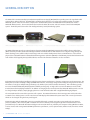
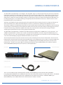
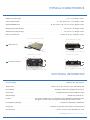
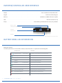
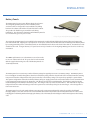
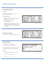
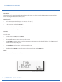
Energy Power Solutions
UPSTEALTH
USER MANUAL
U P S T E A LT H U S E R M A N U A L
BLUEEARTHEPS.COM
CONTENTS
1
General Description
2
General Characteristics
4
Physical Characteristics
Electrical Information
5
Inverter/Controller User Interface
Battery Panel Information
6
Installation
Inverter/Controller
Installation Figures
Battery Panels
HUB
PIM - Power Interface Module
User Interfaces
Inverter/Controller User Display
11
Main Status Screen
Normal Status Display
Power Failure Display
Force On Display
12
System Menu Overview
13
Time and Date Menu
14
Relay Selection & Trigger View Menu
15
System Description & Relay Setup
System Description
Common Panel
Save Panel
On/Off
AC Trigger Menu
Temperature Trigger Menu
Flash Trigger Menu
Time Trigger Menu
Battery Capacity Menu
Relay Status Menu
21
Event Log
22
Setting Power Failure Thresholds & Sensitivity
23
Configuring System Capacity Menu
24
Battery Panel Menu
25
AC Switch
Inverter
Ethernet Communications
26
Maintenance and Troubleshooting
27
Glossary
U P S T E A LT H U S E R M A N U A L / C O N T E N T S
GENERAL DESCRIPTION
The UPStealth is a Battery Backup System/Uninterruptable Power Supply (BBS/UPS) that provides power for signalized traffic
systems when utility power fails. The UPStealth is modular which allows for easy setup and installation within an existing
UPStealth system. There are two basic components in all UPStealth systems: the UPStealth Inverter/Controller and the
UPStealth Battery Panels. The Inverter/Controller contains the DC to AC inverter and is the master control for the BBS/UPS
system. The Battery Panels have their own intelligent battery control/monitoring system.
NEMA UPStealth Battery Panel (500 W)
NEMA UPStealth Inverter/Controller
Living-Hinge UPStealth Battery Panel (500W)
170 UPStealth Inverter/Controller
The UPStealth Battery Panels use unique battery chemistry atypical to BBS/UPS systems in the traffic industry. Nickel-Zinc
(NiZn) chemistry is used instead of the industry standard Lead Acid batteries. NiZn batteries have a higher energy density and
flatter discharge curve, which results in much longer and more reliable backup times than Lead Acid batteries. The reduced
physical size of the NiZn batteries allows Blue Earth Energy Power Solutions (BE EPS) to build Battery Panels that fit between the
rack and the shell of typical primary traffic cabinets. Rack and shelf mounted batteries are also available.
Each Battery Panel has built-in intelligence, which monitors battery performance, charging, maintenance and system status. The
Battery Panel consists of multiple strings of 48VDC NiZn batteries, each string having its own intelligent charger/monitor boards.
The failure of a single or multiple strings of battery cells, within a panel, will not disable the battery. This redundancy greatly
increases the UPStealth Battery Backup System reliability and longevity. A single cable connects the Battery Panels and the
Inverter/Controller simplifying installation. In addition to charging via the Inverter/controller, UPStealth Battery Panels can also
be charged independently by simply plugging them into a standard wall outlet with a supplied Wall Charging Adapter.
The Inverter/Controller controls the operation of the system. The UPStealth monitors the incoming power and decides when
to switch over to battery power. A 4 line x 20 character LCD display shows UPStealth system status and a menu of parameters
which can be changed using the front panel keypad.
Communication with the UPStealth system is accomplished through a network connection using standard secure Internet
protocols (TCP/IP), either remotely with a network connection or directly connecting through the Inverter/Controller’s front
panel Ethernet port. UPStealth Real-Time Intelligence Connect (RTi Connect), will link your computer running Windows or OS X,
to view, monitor and manage UPStealth BBS performance parameters, such as System Status, Cabinet Load, Run-times and AC
Voltage.
1 / U P S T E A LT H U S E R M A N U A L
GENERAL CHARACTERISTICS
The UPStealth Inverter/Controller is an intelligent, Two-Stage BBS. Stage one continuously monitors the power line and decides
if the power available to the traffic cabinet is adequate for safe operation of the traffic cabinet. If utility power is within the user
defined parameter range, it is routed through a transient suppression and filter module to clean up the incoming power. When
utility power is outside of normal operating parameters, a power failure is detected, and the Inverter/Controller will switch over
to battery backup power. The switch to battery power typically takes about 6 milliseconds (msecs). Switch-over times can be
programmed by the user up to 200 msecs.
Stage two, is the digital sine wave monitoring system. This system models the incoming sine wave in real time and detects sine
wave abnormalities. User-settable thresholds allow the end-user to customize the sensitivity of the UPStealth to assure
downstream equipment is completely protected from even the smallest power deviation. When the digital sine wave monitoring
system detects an abnormality, the Inverter/Controller switches the intersection to battery backup and the triggering sine wave
is stored in the Event Log, along with a day/date time stamp. The actual waveform of the power line voltage can help in
analyzing power problems that may be causing equipment malfunctions
The UPStealth Inverter/Controller is available in two different physical configurations: A NEMA version, and a 170 version. The
“NEMA” Inverter/Controller is made to sit on a shelf or be rack mounted. All of the connectors, keypad and LCD display are on
the front of the unit. The “170” Inverter/Controller is 2U high and is rack mountable. The connectors are on the back panel of the
“170” unit and the LCD display, keypad, and Ethernet interface are on the front.
The Inverter/Controller has four plastic circular connectors, where the Battery Panel connector cables attach. This means four
Battery Panels can be directly connected to the Inverter/Controller. If more Battery Panels are needed, an expansion HUB can be
connected to any of the ports on the Inverter/Controller. The HUB will expand the capability of that port to connect to four
Battery Panels. Therefore, if you put a HUB on each Battery Panel Port on the Inverter/Controller, you could have a total of
sixteen (300/500 Watt) Battery Panels connected to one Inverter/Controller.
Four Ports
UPStealth HUB
Barrel Connector
Living-Hinge UPStealth Battery Panel
Cable Connector
There are several different types of Battery Panels available. Standard Battery Panels include the 300 and 500 Watt
Living-Hinge UPStealth Batteries for installation between the rack and the cabinet wall of a 170 style traffic cabinet. The 300/500
Watt Living-Hinge UPStealth Battery Panels fit in 170/2070 33X series traffic control cabinets. A 500 Watt “NEMA” style
UPStealth Battery is also available which can be shelf mounted or rack (19”) mounted.
U P S T E A LT H U S E R M A N U A L / 2
GENERAL CHARACTERISTICS
LED Indicator
Each Battery Panel has a tri-color LED to indicate battery status.
Battery Panels are charged through the Inverter/Controller
cable or independently through a cable that plugs into a
standard wall outlet.
IMPORTANT: It is recommended that Battery Panels be left
connected to a wall outlet if not being used in a system.
Living-Hinge UPStealth Battery Panel
Battery Panels can be added or subtracted from the UPStealth at any time. The Inverter/Controller will recalculate battery
capacity and run time on the fly. Therefore, intersection run-time can be extended by simply adding charged UPStealth Battery
Panels to the installed system. A depleted Battery Panel can be removed and a fresh one added as quickly as it takes to connect
two circular connectors. If an intersection has shut down because the batteries were depleted, the intersection can be brought
back to life by replacing the depleted Battery Panels with fresh ones and then forcing the system back on with the “Force On”
switch.
IMPORTANT: Having depleted Battery Panels and charged up battery panels on the same system is not a problem. A
depleted panel will not “drag down” the charged/good panels because the intelligent battery management system
automatically selects the panel with the most capacity.
Eight Programmable Relays
“Force On”
The Inverter/Controller has eight relays that are user
programmable: Power Failure, Battery Capacity, Time of Day,
Temperature, Flash Time. The relays are considered as ‘Or
Functions’. Meaning, the user can set multiple configurations
under one relay. The configurations are not prioritized, so
whenever a relay configuration parameter is triggered, that
relay will be switched on. Each relay has a common, a normally
closed (NC) contact, and a normal open (NO) contact rated at 2
Amps @120VAC.
NEMA UPStealth Battery Panel
The UPStealth has an Ethernet interface for connection to a computer, local area network, or the Internet. NTC/IP is available for
a SNMP network. A USB port is also available so the software can be updated easily using a flash drive.
3 / U P S T E A LT H U S E R M A N U A L
PHYSICAL CHARACTERISTICS
NEMA Inverter/Controller. . . . . . . . . . . . . . . . . . . . . . . . . . . . . . . . . . . . . . . . . . . . . . . . . . . . 8” x 8” x 17” Weight = 15 lbs
170 Inverter/Controller. . . . . . . . . . . . . . . . . . . . . . . . . . . . . . . . . . . . . . . . . . . 17” (19” w/ears) x 12” x 3.5” Weight = 14 lbs
500 Watt NEMA Battery. . . . . . . . . . . . . . . . . . . . . . . . . . . . . . . . . . . 17” (19” w/ears) x 10” x 3” (3.5” w/ears) Weight = 28 lbs
500 Watt Living Hinge Battery. . . . . . . . . . . . . . . . . . . . . . . . . . . . . . . . . . . . . . . . . . . . . . 19” x 27.35” x 1” Weight = 30 lbs
300 Watt Living Hinge Battery. . . . . . . . . . . . . . . . . . . . . . . . . . . . . . . . . . . . . . . . . . . . . . 19” x 17.25” x 1” Weight = 20 lbs
HUB...(rack mounted). . . . . . . . . . . . . . . . . . . . . . . . . . . . . . . . . . . . . . . . . . . . . . . 19” W x 3.0” H x 3.5” D Weight = 3.7 lbs
Living-Hinge UPStealth Battery Panel (500W)
[19in]
[27.35in]
NEMA UPStealth Battery Panel (500W)
[10in]
[17in]
Battery Panels
[3in]
[1in]
[30lbs]
[17in]
NEMA UPStealth Inverter/Controller
[8in]
[28 lbs]
170 UPStealth Inverter/ Controller
[17in]
[12in]
Inverter/Controllers
[17in]
[8in]
[3.5in]
[19in]
[19in]
[14lbs]
[15lbs]
ELECTRICAL INFORMATION
Conversion Type. . . . . . . . . . . . . . . . . . . . . . . . . . . . . . . . . . . . . . . . . . . . . . . . . . . . . . . . . Intelligent Two-Stage System
Transfer Time. . . . . . . . . . . . . . . . . . . . . . . . . . . . . . . . . . . . . . . . . . 6 milliseconds - User can select up to 200 milliseconds
Power Rating.. . . . . . . . . . . . . . . . . . . . . . . . . . . . . . . . . . . . . . . . . . . . . . 1000 Watts, 1500 optional (3000 W for 30 cycles)
Input Power. . . . . . . . . . . . . . . . . . . . . . . . . . . . . . . . . . . . . . . . . . . . . . . . . 120 VAC 60 Nominal, 80 to 135 VAC 57 to 63 Hz
Output Voltage. . . . . . . . . . . . . . . . . . . . . . . . . . . . . . . . . . . . . . . . . . . . . . . . . . . . . . . . . . . . 120 VAC ±3%, 60 Hz ±0.1%
Isolation. . . . . . . . . . . . . . . . . . . . . . . . . . . The inverter 120 VAC output is completely isolated (1500V) from the Utility power
through the Transfer relays, which perform the Break before Make function
Inverter/Battery Capacity. . . . . . . . . . . . . . . . . . . . . . . . . . . . . . . . . . . . . . . . . . . . 1 to 16 Panels (300 Watts to 8000 Watts)
Charge time. . . . . . . . . . . . . . . . . . . . . . . . . . . . . . . . . . . . . . . . . . 4 Hrs Max, independent of the number of battery panels
Environmental. . . . . . . . . . . . . . . . . . . . . . . . . . . . . . . . . . . . . . . . . . . . . . . -37ºC to +74ºC 5% to 95% Humidity, non cond.
U P S T E A LT H U S E R M A N U A L / 4
INVERTER/CONTROLLER USER INTERFACE
Display. . . . . . . . . . . . . . . . . . . . . . . . . . . . . . . . . . . . . . . . . . . . . . . . . . . . . . . . . 4 Line x 20 Character LCD, LED back lit
Keypad. . . . . . . . . . . . . . . . . . . . . . . . . . . . . . . . . . . . . . . . . . . . . . . . . . . . . . . . . . . . . . . . 5 Mechanical Switch keypad
Ethernet. . . . . . . . . . . . . . . . . . . . . . . . . . . . . . . . . . . . . . . . . . . . . . . . . . . . . . 10/100 Base T, SNMP and Internet capable
USB. . . . . . . . . . . . . . . . . . . . . . . . . . . . . . . . . . . . . . . . . . . . . . . . . . . . . . . . . . . . . . . . . . . . USB 2 for Flash Drives only
Relays. . . . . . . . . . . . . . . . . . . . . . . . . . . . . . . . . . . . . . . . . . . . . 8 isolated Relays with NO and NC contacts, 2A @ 120 VAC
Bypass Switch
Inverter/Controller Interface
USB Port
Ethernet Port
Keypad
170 UPStealth Inverter/Controller
BATTERY PANEL LED INFORMATION
Battery Panel Status:
The Battery Panels have a tri-color LED to indicate status information, as explained in the following table.
STATUS LIGHT
Red to Green to Blue
MEANING
(1 second apart)
Initialization of panel when first connected. Lamp Test
Alternating Blue and Green
Normal operation; no errors.
Solid Green
Normal operation with Wall Adapter Cable.
Solid Blue
Panel is providing backup power.
Blue Blink
(5 seconds apart)
Panel is at 10% or less capacity.
Green Blink
Battery is 100% charged when using the Wall Adapter Cable.
White
Communication with Inverter/Controller.
(Intermittent pulse)
Amber alternating with Blue
Battery waiting for AC so Charging can begin.
Alternating Red and Green
No AC Voltage from Inverter/Controller.
Solid Red
One or more of the Charger Boards has a problem.
5 / U P S T E A LT H U S E R M A N U A L
INSTALLATION
The UPStealth system can be configured to match the power requirements of the traffic cabinet. The minimum system would
include an Inverter/Controller and one Battery Panel. A large system could include one Inverter/Controller, four HUBs with up to
sixteen Battery Panels, and a PIM if there is a need to bypass the UPStealth system while keeping utility power to the cabinet.
The connection between the Inverter/Controller and a Battery Panel is a single cable that contains all necessary signals. Circular
connectors make connecting the cables very easy. A similar cable connects the Inverter/Controller to the HUB.
Inverter/Controller
The connections for the Inverter/Controller are the same whether you are using a NEMA style or the 170 style. The two
Inverter/Controller styles are electrically identical. The AC Input to the Inverter/Controller is usually connected to the utility
power directly or through a Power Interface Module (PIM). Agencies normally run the utility power through a breaker first that
is located on the service panel.
The UPStealth Inverter/Controller has a 20 AMP breaker on its input and output for added protection. It is
recommended that 12 AWG or larger wire be used for power connections. The Phoenix Power connectors can handle up to 8
AWG wire.
Adding a second Terminal Block Service (TBS) to the service panel can greatly simplify wiring to the UPStealth. The second TBS
is used to run power up to the UPStealth AC Input and the AC Output from the UPStealth is connected to the original TBS block.
Electrical equipment that you don’t want connected to the UPStealth can be connected to the added TBS block. The Inverter/
Controller output is not connected to the utility power in any way when operating from battery power. To keep them separated,
you should not connect the AC neutral from the UPStealth to the AC Neutral of the utility power.
When a PIM is used in a system, all connections are made to the PIM. A special cable is used to connect the PIM to the
UPStealth. The utility power is connected to the “AC LINE IN” connector on the PIM either directly or through the second TBS
block. The PIM connector labeled “AC to CABINET” is connected to the original TBS block or the AC+ pin goes to the PDA and
the AC- and Chassis Ground connect to the appropriate buses on the service panel. Figures 1 & 2 show how the various
modules in the UPStealth system are connected together.
The 170 UPStealth Inverter/Controller can be mounted in any location in the cabinet. Important: Make sure that the fan
exhaust on the side of the enclosure is not blocked. The fan will come on when the temperature of the enclosure reaches a
preset threshold.
The NEMA UPStealth Inverter/Controller can sit on a shelf or can be mounted in a 19” rack with the mounting ears. Make sure
that the vents and the fan outlet on the sides of the unit are not blocked by other components when sitting on a shelf.
Power connections are made with finger safe Phoenix Power connectors. These connectors are keyed to prevent the
power wiring from being plugged into the wrong connector. Pulling on the connector or wire cannot unplug these connectors.
The connector has two release slides that must be pushed toward the receptacle before the connector can be removed.
IMPORTANT: When using stranded wire, Do Not solder the wires that are inserted into the phoenix connector. Soldered wire
can loosen with time. The Inverter/Controller also has a standard duplex receptacle to plug the Controller or other equipment
into the Inverter/Controller directly, if desired.
Figures 1 & 2
U P S T E A LT H U S E R M A N U A L / 6
INSTALLATION
Inverter/Controller
The Inverter/Controller has a Real Time Clock that has its own back up power supply that uses Lithium Coin Cells and Super
Caps. The Super Caps will back up the RTC for 24 to 48 hours. The RTC will automatically switch to the Lithium cells when
the Super Caps have discharged. A small slide switch located above the keypad turns the power to the RTC ON and OFF. The
UPStealth is shipped with the switch in the OFF position. DO NOT turn the switch ON until the UPStealth is powered up and
operating. The UPStealth has to configure the RTC before the battery power is enabled or the batteries may be prematurely
discharged.
When power is first applied to the Inverter/Controller, the UPStealth checks the power line, load current and updates the display.
If an Ethernet board is detected, it is also initialized which may take a minute. The UPStealth then determines how many battery
strings (one set of cells that make up a 48 VDC battery) are connected in the system. It doesn’t matter how the battery strings
are physically arranged, just the total number and their charge state. The Inverter/Controller turns the AC power on to each of its
ports to make sure each panel in the system can power up even if the battery voltage is too low to operate normally.
Once the Battery Panel count (and battery string count) is determined, the UPStealth will enter a recovery period where the
battery strings are charged up to a minimum voltage level before they are allowed to supply current to the Inverter/Controller.
This may take a few minutes.
Once the recovery voltage threshold is reached, the capacity is calculated and the battery panels are turned on to supply power
to the Inverter/Controller. When the Inverter/Controller is up and running the Battery Panels go into the normal operating mode.
The Inverter/Controller will then turn the AC off to any unused ports. The UPStealth scans all of the ports regularly to check to
see if any Battery Panels have been added or removed.
When a utility power “event” happens, all of the battery strings are alerted at the same time to turn on their outputs. This
happens within a few microseconds. All of the battery string outputs are combined together to form one large battery. A dead
or partially discharged battery panel will not drag down the other panels. Each battery string is current limited to prevent one
battery string from supplying all of the power.
When the AC power is restored, the UPStealth looks for good power (stable wave forms) for 3 minutes before returning to utility
power. This prevents switching back and forth between the Inverter/Controller power and utility power if the restored AC line
voltage is “noisy”.
The UPStealth determines whether a power failure has happened by two methods: the true RMS value of the AC Line voltage
and/or the occurrence of a “transient” large enough to cause power disruptions. The trip points for the lower and upper voltage
thresholds are set by the user. The user can also select “transient” sensitivity levels that determine if the UPStealth will respond
to a power line anomaly.
The UPStealth determines that a power event has occurred by comparing the incoming power line waveform to a saved
template. This template is created by monitoring the local power line and building a waveform based on the actual local AC
power. The template is continuously updated since the wave shape can change based on the power line loading in the area. The
UPStealth looks for a voltage change for a defined amount of time before it decides a power failure has occurred. The waveform
that tripped the UPStealth is saved in the Event Log along with the template waveform, so power problems can be analyzed.
The “BYPASS” rocker switch on the front panel allows the user to bypass all of the electronics in the Inverter/Controller. The
switch directly connects the “AC INPUT” terminal block with the “AC OUTPUT” terminal block when in the Bypass mode. The
UPStealth will still be operating and it can still monitor the cabinet load current and power. The Inverter/Controller will still
control the Battery Panels and make sure that they are maintained properly. The main purpose of the switch is to bypass the
Inverter/Controller if the user feels it is not operating correctly or the user doesn’t want the battery backup system to operate
while they work on the cabinet.
Figures 1 & 2
7 / U P S T E A LT H U S E R M A N U A L
ǔ
Ǖ
INSTALLATION
Battery Panels
The Battery Panels come in two different physical enclosures.
The Living-Hinge Battery Panels come in flexible plastic
enclosures that are designed for easy installation by sliding
between the cabinet rack and the outside shell of the cabinet.
They need to be flexible to get around the rack during
installation. The cabinet size determines which Battery Panel to
use and how many you can put on a side.
Living-Hinge UPStealth Battery Panel (500W)
The Living-Hinge Battery Panels are installed by first putting the included plastic block in the bottom of the area between the
rack and outside shell. Slipping the “Speedy Sleeve” in the space next to the rack will allow easier installing for the Battery Panel
by covering protruding screws. The Battery Panel can be installed from the front or the back of the cabinet. The Metal cover side
should face the rack. In larger cabinets, one panel can sit on top of another. The Living Hinge Battery panels can be used in any
orientation.
The NEMA style batteries are in aluminum cases and are made
to sit on or underneath a shelf. They can also be rack mounted
with the supplied mounting ears. All of the Battery Panels are
electrically identical.
NEMA UPStealth Battery Panel (500W)
The Battery Panels can contain any number of battery strings but typically have four or six battery strings. Each Battery Panel
has an intelligent controller that gathers data from each battery string, which is relayed back to the Inverter/Controller. Entering
into power fail mode is independent of the panel controller, so the battery strings can respond very quickly to a power failure.
This system configuration allows the individual battery strings to supply power to the Inverter/Controller even if communication
is lost between the Battery Panel, the Controller, each Charger and/or the Inverter/Controller. Each battery string has its own
Controller/Charger that maintains the battery cells. The charger section operates off of the AC line. This makes the charge time
independent of the number of battery panels in the system since each battery string has its own charger. The recharge time is
four hours worst case.
The Battery Panels can be recharged without connection to the main Inverter/Controller using the special included Wall
Charging Adapter. This cable can connect to standard wall AC outlets independent of the Inverter/Controller. The cable can be
left plugged in indefinitely without damaging the battery cells. The Battery Panel intelligence will maintain/protect the battery
cells.
U P S T E A LT H U S E R M A N U A L / 8
INSTALLATION
Battery Panels
As soon as any cable is connected to the Battery Panel, the panel will turn on. If the other end of the cable is not connected to an
Inverter/Controller port or plugged into an AC wall outlet, the Battery Panel will slowly discharge.
IMPORTANT: Do not connect a cable to the Battery Panel if the other end of the cable is not going to be plugged in. The Battery
Panel will eventually completely discharge and shut itself off which will reduce the life of the panel.
Battery Panels can be added or removed at any time in a system. Adding a discharged panel to a system will not hurt the
system. The UPStealth will adjust the capacity and run times when the UPStealth system detects the change in battery strings.
The Battery Panel rating, “300 Watt” and/or “500 Watt” is based on a discharge time of 2 hours. A 500 Watt panel will supply a
250 Watt load for 2 hours. The same 500 Watt panel will supply a 500 Watt load for about 45 minutes.
The UPStealth has a “Force On” mode that allows you to supply power during a power failure to equipment that is not already
connected to a UPS system. To use this feature, install the UPStealth as you normally would. Because there is no AC available
the UPStealth will not start up on its own. To start the system you will manually have to turn the Battery Panel(s) on and then
force the Inverter/Controller on.
After the connections are all made, hold the “Force On” button on the Battery Panel for 5 seconds. The LED Indicator should
show Blue. You may want to do the same for the other Battery Panels if installed. Next, go to the Inverter/Controller and hold
the “Force On” button until the beeping stops. You should now be up and running. Do not use the “Force On” feature if AC is
available.
The Battery Panels continuously monitor the condition of the battery cells, including temperature, discharge current and
charging profiles, so the user gets the maximum life from the Battery Panels. To insure maximum battery life, the control
electronics may extend the charge cycle of the battery strings beyond the normal four hours.
HUB
The expansion HUB allows the installation of more than four UPStealth Battery Panels to a single Inverter/Controller. The HUB
connects to one of the 4 circular connector ports on the back or front of the Inverter/Controller and can control four additional
Battery Panels. Therefore, you can have up to sixteen Battery Panels in a system when you have 4 HUBs installed to an
Inverter/Controller. Each HUB has its own AC power input to supply charging power to the Battery Panels. The AC power
connector should be tied to the utility power and not the BBS/UPS power. During a power failure, the HUB gets its power from
the batteries.
When connecting a system, you should always connect some batteries directly to the main Inverter/Controller before connecting
Battery Panels to the HUB.
The HUB mounts to the rack rails in a standard cabinet. The status indicator is the same as the Battery Panels except that during
a power failure the status LED is a slow blinking Blue.
9 / U P S T E A LT H U S E R M A N U A L
INSTALLATION
PIM
The Power Interface Module (PIM) connects between the cabinet and the UPStealth. The PIM allows the UPStealth to be
removed or disconnected from the cabinet without removing the power from the cabinet. The UPStealth connects to the PIM
with a plastic circular connector making it easy to disconnect the UPStealth from the cabinet. The utility power is connected to
the AC INPUT Terminal Block and the cabinet is connected to the “AC TO THE CABINET” Terminal Block. With the PIM switch in
the “NORMAL” position, power to the cabinet comes through the UPStealth and can provide battery backup. When the switch is
in the “BYPASS” position, power to the cabinet comes from the AC INPUT terminal block and the UPStealth does not supply any
power to the cabinet. The PIM mounts to a rail in the cabinet with the mounting brackets supplied.
User Interfaces
There are two primary ways to directly interact with an installed UPStealth while standing in front of the traffic cabinet: the front
panel LCD display and keypad on the front of the Inverter/Controller or by connecting through the Ethernet port with a laptop
with the installed RTi Connect desktop application. Once connected through the Ethernet port, the technician can see and
manage the UPStealth parameters menu. In addition, a technician can also connect to an installed UPStealth remotely, as long
as the installed UPStealth is connected to a network (see RTi Connect Manual).
Inverter/Controller User Display
The main user interface is the Inverter/Controller front panel keypad and the LCD Display. By moving the cursor on the display
with the “ENTER” key, you can highlight and select menu items. The arrow keys allow you to change the value of the item
selected.
The LCD Display has several screens that allow the user to see all of the status information or set operating parameters of the
system. The following is an overview of each display:
U P S T E A LT H U S E R M A N U A L / 1 0
MAIN STATUS SCREEN
Normal Status Display
Description:
Primary Status screen shown on power up. The
cabinet status is shown here.
Normal Status Display:
ȗ
AC Voltage In: The TRMS AC voltage going into the
BBS/UPS and powering the system.
ȗ
Cabinet Load: Shows the overall
intersection power draw.
ȗ
Backup: The shown time (HH:MM) represents the
available backup time based on the cabinet load.
The percentage represents the overall charge state
of the batteries.
Normal Status Display
Power Failure Display
If a power failure occurs the following display is shown:
Power Failure Display
Force On Display
If the UPStealth is started up with the
“Force On” switch, the display will first show:
The display will automatically switch to the Power Failure Display after the UPStealth has initialized itself.
Controls:
ȗ
To get to the main system menu, press Enter.
ȗ
No other controls on this screen.
1 1 / U P S T E A LT H U S E R M A N U A L
Force On Display
SYSTEM MENU OVERVIEW
Description:
The main system menu. All configuration options can be reached from this screen.
On This Display:
ȗ
TIME/DATE: Set the Inverter/Controller date and time clock.
ȗ
CONFIG: Set the UPStealth to Operate in Standard or High capacity mode.
ȗ
PANELS: View panel detection mode which displays connected panels to verify system configuration.
ȗ
RELAYS: Brings up the screen for viewing and setting relay triggers.
ȗ
EVENT LOG: Shows the past 74 system events, such as, power failure, configuration change, internal error, etc.
ȗ
MORE: Provides access to the AC Switch and Ethernet Menus
ȗ
INVERTER: Allows for configuring and viewing the brownout thresholds and power monitor sensitivity.
ȗ
BACK: Returns to the Main Screen.
Controls:
ȗ
Use the direction keys to move the cursor.
ȗ
To select an option, move the cursor over the appropriate title and press ENTER.
System Menu Display
U P S T E A LT H U S E R M A N U A L / 1 2
TIME & DATE MENU
Description:
This is the screen for setting/viewing the time and date of the system. This clock is used for all time stamps on events and timebased relay triggers. This clock uses military time.
On This Display:
ȗ
T: The current system time, displayed as hh:mm:ss (hh = 0 to 23)
ȗ
D: The system day, displayed as MM/DD/YY.
ȗ
SET: Change the date and time of the system.
ȗ
BACK: Returns to the main system menu.
Controls:
To set the time:
ȗ
Move the cursor over SET, and press ENTER.
ȗ
The cursor will now move into the time area of the screen.
ȗ
Press UP/DOWN to change a value. If it reaches a maximum or minimum value, the value will “rollover” (e.g, if UP is pressed
when the minutes is 59, it will go to 0).
ȗ
Press LEFT/RIGHT to select a value, such as hour, min, day, etc.
ȗ
When finished, press ENTER to save The changes. The cursor will return to the BACK option.
Notes:
ȗ
The seconds of the system cannot be set.
Time and Date Menu Display
1 3 / U P S T E A LT H U S E R M A N U A L
RELAY SELECTION & TRIGGER VIEWING MENU
Description:
View all 8-relay settings and select a relay to configure. This display is configured as two columns, one column has the relay
number (under the STATUS heading) and the second column shows the Trigger for enabling the relay. When a RELAY is enabled,
The COM pin and the NO (normally open) Pin are connected.
On This Display:
ȗ
RELAY(#): Brings up the settings menu for that relay.
ȗ
TRIGGER: What the relay will trigger on. Values can be:
AC
TEMP
TIME
FLASH
BATTCAP
MULTI
In the below screenshot, Relay1 is not configured to trigger, Relay2 will trigger on a power failure.
Controls:
ȗ
Use the direction keys to select a relay. Press ENTER to go to the configuration screen for that relay.
ȗ
The screen scrolls, allowing access to all the relays. BACK will always be at the very top, and the last relay will always be at
the very bottom.
Relay Selection and Trigger Viewing Menu Display
U P S T E A LT H U S E R M A N U A L / 1 4
SYSTEM DESCRIPTION & RELAY SETUP
System Description
The UPStealth has 8 user-configurable relays that can trigger on a power failure, time of day, temperature, flash time, and at a
given battery capacity.
Each relay can be assigned to any of these triggers. Likewise, any relay can have more than one trigger type, in which case the
relay will trigger if any of the conditions occur.
When configuring a relay, each trigger is turned on separately for that relay. On factory default, all triggers for all relays are off.
The left side is known as the “Common Panel”, and the right side is the “Trigger Panel”. These are divided by the vertical dashed
line. There is a unique trigger panel for each trigger option.
Settings such as temperature bounds
and times will be saved even when a
trigger is turned off.
The following information is common
to all applicable configuration screens.
Relay Setup and System Display
Common Panel
Except when saving, this will be displayed on the left side of the screen.
On This Display:
ȗ
RLY (#): The relay that is being configured. This will always be present
on every relay configuration menu.
ȗ
NEXT: Moves to the next trigger configuration panel (Such as from AC
to TEMP).
ȗ
SET: Configure the trigger for the relay. This will move the cursor into
the trigger panel, allowing for input of configuration options.
ȗ
BACK: Returns to the relay selection screen.
Controls:
ȗ
Select one of the options with the directional arrows; press ENTER.
1 5 / U P S T E A LT H U S E R M A N U A L
UPStealth Interface
SYSTEM DESCRIPTION & RELAY SETUP
Save Panel
This will be displayed over the common panel to confirm the settings before making them active. The common panel will
reappear after answering YES or NO.
On This Display:
ȗ
NO: Changes will be discarded.
ȗ
YES: Changes will be saved and made active.
Controls:
ȗ
Same as the Common Panel.
Notes:
ȗ
The settings to be saved will be exactly as shown on the trigger
configuration screen, allowing for easy review.
UPStealth Interface
On/Off
ȗ
To easily see what triggers are on, either use the relay selection menu (when there is not a relay set to multiple triggers) or
scroll through the trigger panels looking at which box is checked at the bottom of the trigger pane.
Trigger is ON for that relay:
UPStealth Interface
Trigger is OFF for that relay:
UPStealth Interface
U P S T E A LT H U S E R M A N U A L / 1 6
SYSTEM DESCRIPTION & RELAY SETUP
AC TRIGGER MENU
To Setup an AC Trigger:
ȗ
Select NEXT to get to the AC trigger panel if not
already on it.
ȗ
Select SET. The cursor will now be in the trigger
pane.
ȗ
Use the directional arrows to select ON or OFF.
ȗ
Press ENTER. The save menu will appear, and the
cursor will move to it.
ȗ
Review changes and select YES.
ȗ
The relay is now configured. The Relay will stay
enabled for the length of the Power Failure.
AC Trigger Menu Display
TEMPERATURE TRIGGER MENU
To Setup a Temperature Trigger:
ȗ
Select NEXT to get to the temperature trigger panel
if not already on it.
ȗ
Select SET. The cursor will now be in the trigger
pane.
ȗ
Press LEFT/RIGHT to move the cursor to the value
needing to be changed.
ȗ
Press UP/DOWN to change the value of a
temperature trigger point.
ȗ
After entering the bounds, move the cursor to ON
or OFF.
ȗ
Press ENTER. The save menu will appear and the
cursor will move to it.
ȗ
Review changes and select YES.
ȗ
The relay is now configured.
1 7 / U P S T E A LT H U S E R M A N U A L
Temperature Trigger Menu Display
ȗ
The “UPPER” value is the temperature that triggers the
relay on as the temperature increases. There is a 10
degree hysteresis before the relay will turn off. The
“LOWER” value is the temperature that will turn the
relay on when the temperature is decreasing. The above
display setup will turn relay 1 on when the temperature
is 120F and above. It will shut off when the temperature
drops to 110F degrees. Relay 1 will turn on again when
the temperature drops to 10F degrees and below and
then turns off when the temperature warms up to 20F
degrees.
SYSTEM DESCRIPTION & RELAY SETUP
FLASH TRIGGER MENU
The “FLASH” time is the length of time after a power failure is detected that the relay will be energized. The relay can be used to
put a cabinet into Flash after the power has been out for a certain period of time. It can also be used to inform the traffic center
that an area has had a power failure that has lasted a certain amount of time.
To Setup a Flash Trigger:
ȗ
Select NEXT to get to the flash trigger panel if not
already on it.
ȗ
Select SET. The cursor will now be in the trigger
pane.
ȗ
Press LEFT/RIGHT to move the cursor.
ȗ
Press UP/DOWN to change the flash time. The time
changes in increments of 15 minutes.
ȗ
After entering the flash time, move the cursor to ON
or OFF.
ȗ
Press ENTER. The save menu will appear and the
cursor will move to it.
ȗ
Review changes and select YES.
ȗ
The relay is now configured.
Flash Trigger Menu Display
U P S T E A LT H U S E R M A N U A L / 1 8
SYSTEM DESCRIPTION & RELAY SETUP
TIME TRIGGER MENU
This image shows the user how to activate a relay based on the time of day, everyday.
To Setup a Time Trigger:
ȗ
Select NEXT to get to the time trigger menu if not already on it.
ȗ
Select SET. The cursor will now be in the trigger pane.
ȗ
Press LEFT/RIGHT to move the cursor to the value needing to be changed.
On this screen, the cursor can move between the hours and minutes of the start
and end times, as well as the ON and OFF buttons.
ȗ
Press UP/DOWN to configure the times. Note that the system uses military time.
ȗ
After entering the start and end times, move the cursor to ON or OFF.
ȗ
Press ENTER. The save menu will appear and the cursor will move to it.
ȗ
Review changes and select YES.
ȗ
The relay is now configured.
Time Trigger Menu Display
1 9 / U P S T E A LT H U S E R M A N U A L
SYSTEM DESCRIPTION & RELAY SETUP
BATTERY CAPACITY TRIGGER MENU
This menu allows you to control a relay based on
battery capacity during a power failure. When the
battery capacity drops below the set battery capacity,
the relay is turned ON. The relay can be used to put the
cabinet into Flash so the backup time can be increased.
To Setup a Battery Capacity Trigger:
Select NEXT to get to the battery capacity trigger panel,
if not already on it.
Battery Capacity Trigger Menu Display
Select SET. The cursor will now be in the trigger pane.
Press LEFT/RIGHT to move the cursor.
Press UP/DOWN to change the capacity trigger point.
After entering the capacity point, move the cursor to ON
or OFF.
Press ENTER. The save menu will appear and the cursor
will move to it.
Review changes and select YES.
The relay is now configured.
RELAY STATUS MENU
Selecting “STATUS” from the Relay menu brings up the
follows display:
The real time status of all 8 relays is shown on this
display. The “C” under the R1 relay heading indicates
that Relay 1 is energized and the normal open contact
is Closed. The “O” under the other relay headings indicates that the other relays are not energized and the
normal open contacts are Open.
Relay Status Menu Display
This display shows status only and has nothing that can
be changed by the user.
U P S T E A LT H U S E R M A N U A L / 2 0
EVENT LOG
Description:
This screen displays the events recorded by the BBS/UPS, such as a power failure, configuration change, or other important
events.
On This Display:
ȗ
EVENT: The type of event, such as a power failure.
ȗ
T: and D: The time and date of the event.
ȗ
BACK: Returns to the main system menu.
The last line of the screen will display information specific to the type of event. In the pictured example (a power failure), it
shows the duration of the event.
Controls:
ȗ
Press LEFT or RIGHT to scroll through the event log.
ȗ
To return to the main system menu, press ENTER.
Notes:
ȗ
The event log will show the newest event first. The oldest event will be furthest to the right, and the newest event will be
furthest to the left. The arrows on the top of the screen will reflect this.
ȗ
If no events have been recorded, the screen will display “No Events”.
ȗ
Upon reaching the end of the log, the screen will display “End of Log”.
Event Log Display
2 1 / U P S T E A LT H U S E R M A N U A L
SETTING POWER FAILURE THRESHOLDS & SENSITIVITY
INVERTER THRESHOLDS
This menu sets how the UPStealth responds to power anomalies. The voltage thresholds for brown out levels and the over voltage point can be set by the user. You can also set how sensitive the UPStealth is to power line “transients” and dropouts.
Description:
This screen allows for the configuration of the AC Power Monitoring thresholds.
On This Display:
ȗ
L THRESH: Power Failure voltage (or brownout) threshold.
ȗ
H THRESH: Upper Power Failure threshold, if concerned about a power surge.
ȗ
SENSITIVITY: How sensitive the power monitoring system is. This can be one of five values:
The value it should be set as depends on the level of noise on the AC line in the area and application.
ȗ
SET: Allows for configuring and viewing the brownout thresholds and sensitivity of the power monitor.
ȗ
BACK: Returns to the Main Screen.
Controls:
To set the thresholds and sensitivity:
ȗ
Select SET, and press ENTER.
ȗ
The cursor will now be in front of the lower threshold.
ȗ
Press LEFT/RIGHT to select the value to change.
ȗ
Press UP/DOWN to change the voltages or sensitivity levels.
ȗ
When finished, press ENTER.
Thresholds Display
XHI
Very Sensitive - Faster response, more likely to false trigger on noise.
HI
Sensitive
MED
Normal
LOW
Less sensitive
XLO
Very low sensitivity - Slower response, disregards noise.
U P S T E A LT H U S E R M A N U A L / 2 2
CONFIGURING SYSTEM CAPACITY MENU
Description:
This menu selects the system capacity mode of the UPStealth. When HIGH CAPACITY is enabled, the batteries will be allowed
to discharge below their optimum cutoff point, allowing for greater available backup time. While high capacity mode does not
harm the batteries or the system, the lower cutoff point will decrease the overall longevity of the batteries. The high capacity
mode adds about 20% to the backup time. If you have infrequent power failures, you may not notice any reduction in battery
life.
On This Display:
ȗ
HIGH CAPACITY MODE: The mark indicates if the mode is turned on or off.
ȗ
SET: Allows the mode to be turned on or off.
ȗ
BACK: Returns to the main system menu.
Controls:
To set high capacity mode:
ȗ
Move the cursor over SET, and press ENTER.
ȗ
The cursor will now move into the on/off area of the screen.
ȗ
Press UP/DOWN to change the value.
ȗ
When finished, press ENTER to save the changes. The cursor will return to the BACK option.
Notes:
ȗ
The user should decide if battery longevity or backup time is most critical in their application. By default, this mode is
turned off.
System Capacity Display
2 3 / U P S T E A LT H U S E R M A N U A L
BATTERY PANEL MENU
Description:
This screen tells the Inverter/Controller to look for new panels and displays/verifies the connected panels. A simplified diagram
of the battery connectors is shown as viewed from the back of the controller.
On This Display:
ȗ
ADD PANEL: Places the unit into panel detection mode.
ȗ
BACK: Returns to the main system menu.
ȗ
DIAGRAM: If the box is marked, the panel in that port has been connected and initialized by the system. An “M” in the box
means a HUB with multiple panels is connected to the port.
Controls:
To enter panel detection mode:
ȗ
Move the cursor over ADD PANEL, and press ENTER.
ȗ
The cursor will now move and the waiting menu will appear.
ȗ
Connect panels and wait for the mark(s) to appear in the diagram. Press ENTER when finished connecting Battery Panels. It
will not automatically exit detection mode, allowing the user to verify each panel as it is installed.
Notes:
ȗ
Simply stated, this menu will speed up the detection of a UPStealth Battery Panel.
Battery Panel Menu Display
U P S T E A LT H U S E R M A N U A L / 2 4
AC SWITCH DELAY
The switching time from power failure to switch-over to Inverter/Controller power can be set by the user. The range is from
about 6 msecs to 200 msecs. The default is 6 msecs, which is the fastest time. The user may want to extend the time if they have
some equipment that might be upset by the fastest switching times. You might want some equipment to completely power
down during a power failure.
The 00 ms time represents 6 msec. The time can be set in 8 msec steps.
To set the delay time, move the cursor to “SET” and Press “ENTER”.
Use the UP and Down keys to adjust the value and press “ENTER”.
AC Switch Display
ETHERNET COMMUNICATIONS
The Ethernet Display shows the IP address and the MAC Address for the Ethernet Board. There is nothing to change or adjust on
this display.
Ethernet Communications Display
2 5 / U P S T E A LT H U S E R M A N U A L
MAINTENANCE & TROUBLESHOOTING
There is no required maintenance on the UPStealth system. The Battery Panels automatically perform health procedures and
maintain the cells to ensure the longest possible life. A Battery Panel that is not being used in a system should be connected to
our charging cable and left plugged into an outlet. This will assure the panel will be ready to be used if needed.
IMPORTANT: If a Battery Panel is not going to be connected to an AC outlet, the Battery Panel SHOULD NOT have a cable
connected to it. A Battery Panel that is in storage and not being used should be charged up at least every Month to maintain a
good life expectancy.
A Battery Panel that has been connected to a cable but not charged for an extended period (a week or so) may not start on its
own when connected to an AC source because its voltage has dropped too low. A Panel in this condition will require a factory
reset and should be returned to the factory for a recharge and retest.
The Status Lights and the main display will inform the user if there is a problem with any part of the UPStealth system. There are
no user serviceable parts in the UPStealth except for changing out Battery Panels.
U P S T E A LT H U S E R M A N U A L / 2 6
GLOSSARY
AC Power
MOV
AC-
msec
AC Power grounded return
Milli-seconds - one thousandth of a second
AWG
NC
American Wire Gauge
Normally Closed Contact (circuit completed)
BBS
NEMA
AC+ Utility power typically 120 VAC 60 Hz
Battery Backup System
EG
Equipment Ground
ETHERNET
A system for connecting a number of computer systems to form a
local area network to control the passing of information between
them
F
Fahrenheit
Firmware
Computer Code that resides in a board level product.
Flash
Nonvolatile Memory
IP
Internet Protocol
KB
Kilobyte
LED
Light Emitting Diode
LCD
Liquid Crystal Display
Living Hinge
Metal Oxide Varistor (Transient Suppressor)
National Electrical Manufacturers Association.
(Traffic Cabinet)
Nickel-Zinc
Rechargeable battery chemistry that uses Nickel and Zinc (NiZn)
NO
Normally Open Contact (circuit not complete)
NTCIP
National Transportation Communication for ITS Protocol
PCB
Printed Circuit Board
PDA
Power Distribution Assembly
PWM
Pulse Width Modulation
SNMP
Simple Network Management Protocol - An Ethernet protocol
allowing a master computer to poll other computers in a local area
network
SOFTWARE
Computer code that usually resides in a PC or higher level
computer
VAC
Volts Alternating Current
A flexible plastic bearing that allows the UPStealth Battery Panels
to bend
VDC
MB
UPS
Megabyte
MOS
Metal Oxide Semiconductor
U P S T E A LT H U S E R M A N U A L / 2 7
Volts Direct Current
Uninterruptible Power Supply
uSEC
Micro-second - one millionth of a second
P O W E R E D BY B LU E E A RT H
Energy Power Solutions
Blueeartheps.com
Twitter.com/BlueEarthEPS
Facebook.com/BlueEarthEPS
B [email protected]
U P S T E A LT H U S E R M A N U A L
UPSTEALTH USER MANUAL
BLUEEARTHEPS.COM
[email protected]
U P S T E A LT H U S E R M A N U A L