1
University of Saskatchewan
Electrical Engineering Laboratory Equipment Manual
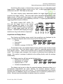
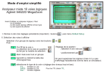
The display of this scope conveys much information. At the top left side of the
screen you will find the channels that are on, as well as their volts/div setting and
coupling. For instance, 1 2.00V 2 P5.00V means that channel 1 is set to 2 V/div and is
dc coupled. Channel 2 is set to 5 V/div and is ac coupled.
In the top middle of the screen is an arrow and a time. That is the time that
corresponds to the middle of the screen in the current acquisition. Just to the right of it
you will find the current time/div setting. Somewhere along the top display line you will
find an upside down solid triangle. At the bottom of the screen you will find a right-side
up solid triangle immediately beneath it. These triangles denote the t = 0 point of the
acquisition.
In the top right corner of the display you will find information about the trigger
source, mode, and slope. Lastly, either RUN or STOP will be displayed to the right of
the triggering information, indicating whether the scope is actively acquiring data or has
stopped.
Along the right edge of the display you will see a channel number along with a
ground circuit symbol with an arrow pointing to the left. That indicates the ground (0 V)
position for that channel. If the ground position is off screen, then the channel number
and an arrow will be displayed at either the top or bottom of the screen to show where
the ground level is.
Channel Menus and Vertical Controls
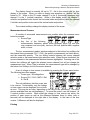
Pressing either channel menu (1 or 2) brings up a list of items adjacent to the six
softkeys at the bottom of the display. These menu items are as follows:
• Channel off/on
• Coupling dc/ac/ground
• Bandwidth limit off/on
• Invert off/on
• Vernier off/on
• Probe 1/10/100
If you select ground coupling for a channel, that internally connects the input to
ground. If the bandwidth limitation is turned on, the channel is low-pass filtered with a
cutoff of 20 MHz. Invert does as you expect – inverts the waveform. When the Vernier
is turned on, the volts/div for that channel changes in fine steps. When it is off, it
changes in coarse steps. Normally the Vernier is left off.
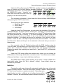
The volts/div for each channel are adjusted using the large
Volts/Div adjust knobs. Turn them counterclockwise to increase the
volts/div; turn them clockwise to decrease it. The position knobs
control the vertical position of the waveforms on the screen by moving
the ground position of each waveform up or down.
Revised: Sept. 2009, J. Kowalski
Page 3 of 25