1
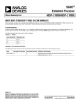
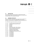
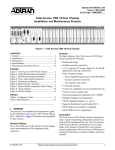
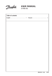
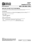
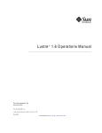
Engineer To Engineer Note
a
EE-189
Technical Notes on using Analog Devices' DSP components and development tools
Contact our technical support by phone: (800) ANALOG-D or e-mail: [email protected]
Or visit our on-line resources http://www.analog.com/dsp and http://www.analog.com/dsp/EZAnswers
Link port tips & tricks for ADSP-2106x & ADSP-2116x SHARC® DSPs
Contributed by R. Murphy
Introduction
Some members of the SHARC® DSP family
have Link Ports that enable point-to-point
communication between DSPs. This EE-note is
intended
to
supplement
the
existing
documentation and facilitate debugging Link
Port systems. In this EE-note we will briefly
cover the basics of using link ports, provide
some tips on link port operation across the
SHARC DSP family, and discuss the anomalies
associated with some of the Link Port
functionality.
Why Use Link Ports?
• Point-to-Point Inter-processor Communication
Use the Link Ports to transfer data amongst
the DSPs in the cluster, freeing up the external
port for other accesses.
• Flexible, efficient data control
Link Ports can use the core or the zerooverhead DMA controller to transfer data to /
from the DSP for efficient data I/O.
• Bi-directional communication on a single link
The Link Ports are bi-directional, so a routine
can easily switch the direction of the transfer.
• Multiple simultaneous transfers
The Link Ports allow the DSP to
communicate with other DSPs simultaneously
saving time and board layout.
October 27, 2003
• Suitable for long distance transfers
Sending the data along with the LACK (Link
Acknowledge) signal as well as the ability for
LACK to hold off further words lends itself to
long trace-length usage.
• Link Port Booting
The ability to boot the DSP via the link port
can further free up the external bus and allows
for complex booting schemes in which many
DSPs can be booted in sequence via link
ports, even with unique application code for
each DSP.
The Basics
Link Ports Availability by DSP
ADSP-21060 & ADSP-21062:
6 Link ports, 4 bits wide, 1x or 2x core clock
ADSP-21160:
6 Link ports, 8 bits wide, up to 95* MHz
ADSP-21161:
2 Link ports, 8 bits wide, up to 100 MHz
*ADSP-21160M = 80MHZ, ADSP-21160N = 95MHz
!
The ADSP-2106x and ADSP-2116x Link Ports
are logically but not electrically compatible.
Please see EE-160 on www.analog.com/sharc
for more information on using these peripherals
together.
Copyright 2003, Analog Devices, Inc. All rights reserved. Analog Devices assumes no responsibility for customer product design or the use or application of
customers’ products or for any infringements of patents or rights of others which may result from Analog Devices assistance. All trademarks and logos are property
of their respective holders. Information furnished by Analog Devices Applications and Development Tools Engineers is believed to be accurate and reliable, however
no responsibility is assumed by Analog Devices regarding technical accuracy and topicality of the content provided in Analog Devices’ Engineer-to-Engineer Notes.
A
Link Port Buffers:
port to any link buffer, and each link buffer has a
dedicated DMA channel. In order to prevent lost
data, a read of an empty buffer or a write to a full
buffer results in core hang.
These are Memory Mapped two location deep
FIFOs with support for either 32 or 48 bit words.
The user has the flexibility to assign any link
Transmitter
Receiver
4/8
Each
LDATx
LDATx
LCLKx
LCLKx
Link
Port
Each
Link
LACKx
SHARC
LACKx
Port
SHARC
Figure 1 .Link Port Connections 21xxx DSPs
Figure 1 displays the connection of the link port
signals. The data path is 4 bits wide on the
ADSP-2106x DSPs, and configurable for either 4
or 8 bits wide on the ADSP-2116x DSPs. The
LDATx and LCKx signals are driven by the
transmitter. LACKx is driven by the receiver.
Data is driven on the rising edge of LCLKx and
sampled on the falling edge. The receiver will
deassert the LACKx signal to hold off the
transfer if it’s link buffer is full.
Figure 2.Link Port Communication Examples
Link port tips & tricks for ADSP-2106x & ADSP-2116x SHARC® DSPs (EE-189)
Page 2 of 6
A
Figure two displays possible link port
communication schemes. It also highlights the
ability of the link ports to work in conjunction
with the External Port, to connect SHARC DSPs
within a cluster, as well as to tie clusters
together. Up to six SHARC DSPs can be used
together in a multiprocessing cluster, sharing
external memory via the external port, and
multiple clusters can be tied together using the
link ports.
vector as in the DMA instance above.
LSRQ: Link Port Service Requests allows an
external device to initiate a Link Port transfer,
even though the Link Ports & Buffers are not
initialized. When the external device asserts
LxCLK or LxACK, an LSRQ interrupt is
generated. The ISR should poll the LSRQ
register to determine which Link Port to initialize
and the direction of transfer.
Link Port Registers and Settings
Link Port Interrupts
There are three types of interrupts associated
with the Link Ports. They are DMA, Non-DMA,
and LSRQ:
DMA: An interrupts is generated at the
completion of the DMA, i.e. when the DMA
count has decremented to zero.
Non-DMA: When DMA is not enabled, a Link
Port Interrupt will be generated when the Rx
buffer is not empty or when the Tx buffer is not
full. These interrupts use the same interrupt
While most of the Link Port functionality is
shared across the SHARC family, the register
names and settings are not. Table 1 lists the
names of registers in each family. Among the
key differences to note are that the ADSP-2106x
family Link Ports supported speeds of 1x or 2x
the Core Clock rate, and the newer ADSP-2116x
DSPs support 1x, 1/2x, 1/3x, 1/4x. Also note that
the data-word width is selectable in the 2116x
family for either 4 or 8-bits.
ADSP-2106x
ADSP-21160
ADSP-21161
LCOM, LCTL, LAR
LCOM, LCTLx, LAR LCTL
Link Buffer Status
LCOM
LCOM
LxSTAT bits in LCTL
Port to Buffer Assignment
LAR
LAR
LABx bits in LCTL
Word size 32/48
LxEXT bit in LCTL LxEXT in LCTLx
LxEXT bit in LCTL
Transmit/Receive
LxTRAN bit in
LCTL
LxTRAN bit in
LCTLx
LxTRAN bit in LCTL
DMA, Chaining
LxDEN, LxCHEN
bits in LCTL
LxDEN, LxCHEN
bits in LCTLx
LxDEN, LxCHEN bits in LCTL
4 or 8 bit data path
4 bits always
LxDPWID in LCTLx LxDPWID bit in LCTL
LCLK rate
1x or 2x core clock
LxCLKD bits in
LxCLKD bits in LCTL
LCTLx (1:1, 1:2, 1:3,
LCLKX2x in LCOM
(1:1, 1:2, 1:3, 1:4)
1:4)
Table 1: Link Port Register Names
Link port tips & tricks for ADSP-2106x & ADSP-2116x SHARC® DSPs (EE-189)
Page 3 of 6
A
Silicon Anomalies
Table 2 summarizes some of the Link-Portspecific anomalies that can cause problems if not
accommodated. Please see the respective
Anomaly list for each part for further
information. This table is provided as a summary
only. SHARC Silicon Anomaly Lists are
maintained online at www.analog.com/sharc
Anomaly
Exists in
Specifics
Workaround
Transfers fail at 2x
21060 & 21062 (3.3 -Manifests as corrupted first nibble -Use 1x speed
volt & 5 volt)
of transfer
-Exacerbated by high operating
temp and asynchronous CLKINs
Throughput limited 21160M,
21160N, No data loss, just 2 cycle stall for
for 32 bit transfers in 21161N all revisions every other word transmitted
1:1 ratio
-Use 1:2, 1:3, 1:4 ratio
-Use 48 bit transfers
Core driven transfers 21160M 0.x
may fail if you
overrun the buffer
Can’t rely on the core to hang on a -Use DMA
read/write of a empty/full buffer
-poll link buffer status bits
Change in direction
Tx --> Rx corrupts
first word
1st byte of 1st word corrupted, other -Send a dummy word after
data ok
changing from Tx to Rx
21160M 0.x
Link to Link transfer 21160M all revisions Receiver sample / hold issue
are not reliable at all
frequencies
-See throughput table in ADSP21160 Datasheet
-Use ½ core clk rate
Data corruption may 21160M all revisions, Typically only seen in boards where -Use 1/2x, 1/3x, 1/4x ratio
occur in a particular 21161N 0.3
each DSP has it’s own CLKIN
-Synchronize CLKIN sources
alignment of LCLK
source
& CLKIN
Buffers & status bits 21160M all revisions, Affects Link ports setup as Tx only, -Setup a dummy transfer
flaky out of /RESET 21161N 0.3, 1.0, 1.1, not Rx
-Write the LBUF manually with
fixed in 1.2
the 1st two words to overwrite
the buffer junk
Table 2: Link Port-specific silicon anomalies
Booting
For a DSP configured to boot in Link Port mode,
Link Port 0 (Link Port 4 in ADSP-21160) is
initialized to receive via DMA channel 8 the 256
word kernel. The boot mode is selected at reset
by the boot configuration pins. The link boot
kernel is then executed and copies in the
remainder of the application code one 48-bit
word at a time, using multiple transfers and
unpacking the data into instructions, and finally
it uses a DMA to overwrite itself with the
beginning of the application code.
The ‘master’ DSP is either booted via a Link
Port from an upstream SHARC or from an
Link port tips & tricks for ADSP-2106x & ADSP-2116x SHARC® DSPs (EE-189)
Page 4 of 6
A
EPROM or Host. The ‘master’ can simply
includes the loader file (application code) or it
can copy it from the host or EPROM and set up a
DMA to send it out to the other DSPs Link port.
The link ports can be used in this manner to
setup to boot a large number of DSPs, each with
unique source code. The booted DSPs can in turn
boot the other DSPs in their respective clusters
via link ports or another peripheral. For more
information on booting please refer to EE-77,
SHARC Link Port Booting.
Things to watch out for
Stalls:
• -There is a 1-cycle stall incurred following 2
successive link buffer reads.
• -An N cycle stall (core hang) is incurred on a
read from an empty buffer or a write to a full
buffer.
When using DMA:
• disable the link port directly following the
DMA completion will cause that data to be
lost. Instead poll the buffer status bits and
write LCTL when the buffer reports being
empty.
Misc.:
• -When using 48-bit word length at 100 MHz,
the LACK signal is de-asserted after every 48bit word transmission. (key when interfacing
to transceivers)
• -Link port cables for EZ-kits: Analog Devices
third-party Transtech-DSP (www.transtechdsp.com) sells link port cables that are
compatible with the connectors on the 2116x
ez-kits, however these cables are intended for
the ADSP-TS101S ez-kit, and will not work
with the 2116x ez-kits. Look in the resources
section at the end of this document for a link
to EE-106, a standard for cabling materials
and design that will work reliably at the
100Mhz operating frequency.
• -When the DMA completes, there are still 2
words in the Link Buffer. A write to LCTL to
Link port tips & tricks for ADSP-2106x & ADSP-2116x SHARC® DSPs (EE-189)
Page 5 of 6
A
References
[1] ADSP-2106x SHARC® User’s Manual, Second Edition
[2] ADSP-21161 SHARC® DSP Hardware Reference Manual, Third Edition
Resources:
(available at http://www.analog.com/SHARC)
[3] Using Token Passing to Control SHARC Link Port Bi-directional Communication (EE-16)
[4] SHARC Link Port Timing Notes (EE-41)
[5] ADSP-2106x Link Ports - Maximum Throughput (EE-47)
[6] SHARC Link Port Booting (EE-77)
[7] Link Port Open Systems Interconnect Cable Standard (EE-106)
[8] Examining ADSP-21160 Link Port Backward Compatibility to the ADSP-2106x Link Ports (EE-160)
Document History
Version
Description
October 27, 2003 by R. Murphy.
Revision of Anomaly Information
March 20, 2003 by R. Murphy.
Initial Draft Release
Link port tips & tricks for ADSP-2106x & ADSP-2116x SHARC® DSPs (EE-189)
Page 6 of 6