1
EMPB2 USER MANUAL
This document is the property of EM MICROELECTRONIC-MARIN SA and is furnished in confidence and upon the condition that all rights originating
in the information, whether patented or not, will be respected.
EM Document Center / rev. C-08.06 - Page 1 of 9
TABLE OF CONTENTS / TABLE DES MATIERES
1.
GENERAL PRESENTATION.............................................................................................................................3
1.1
1.2
1.3
1.4
1.5
2.
HARDWARE DESCRIPTION.............................................................................................................................4
2.1
2.2
2.3
2.4
2.5
2.6
3.
ISP connector...........................................................................................................................................................4
USB CONNECTOR..................................................................................................................................................4
ISP CABLE...............................................................................................................................................................4
Electrical considerations...........................................................................................................................................4
Device connections ..................................................................................................................................................5
Note concerning EM6580.........................................................................................................................................5
SOFTWARE DESCRIPTION .............................................................................................................................6
3.1
3.2
3.3
4.
FEATURES ..............................................................................................................................................................3
REQUIREMENTS ....................................................................................................................................................3
SOFTWARE .............................................................................................................................................................3
MICROCONTROLLER DEVICE SUPPORT ............................................................................................................3
Deliverables .............................................................................................................................................................3
Installation procedure ...............................................................................................................................................6
EMPB2 software - GUI .............................................................................................................................................8
EMPB2 software – COMMAND LINE.......................................................................................................................8
KNOWN LIMITATION, BUGS, TROUBLESHOOTING.....................................................................................9
This document is the property of EM MICROELECTRONIC-MARIN SA and is furnished in confidence and upon the condition that all rights originating
in the information, whether patented or not, will be respected.
EM Document Center / rev. C-08.06 - Page 2 of 9
EMPB2 USER MANUAL
1.
GENERAL PRESENTATION
EM Programming Box 2 (EMPB2) is a very compact, easy-to-use and low-cost EM programmer. This
programmer is able to program all the standard EM Microcontrollers. EMPB2 support only ISP (In-SystemProgramming) – no socket provided. EMPB2 is USB powered and does not require any additional powersupply. The Software can be launched with its GU (Graphical User) Interface or through command from dos
shell or any other application.
1.1
FEATURES
ISP programming
Support all the standard EM Microcontrollers
EMPB2 software
USB communication and powered – No additional power-supply needed
Totally upgradeable by software
GUI and/or batch
1.2
REQUIREMENTS
Pentium processor
10 MB Free Hard Disk Space
64 MB RAM
USB port (USB 1.1 and USB 2.0 compatible)
Windows 98 / 98 SE / 2000 / ME / XP
1.3
SOFTWARE
EMPB2 Software can be downloaded: Please visit our website http://www.emmicroelectronic.com { go
through Low Power Microcontroller ► MCU Tools ► EMPB2 } or contact EM Microelectronic-Marin.
New devices will be added in the new versions of EMPB2 software. We recommend using the latest
release available. No hardware upgrade procedure required (no firmware).
1.4
MICROCONTROLLER DEVICE SUPPORT
4-bit EEPROM
4-bit FLASH
8-bit FLASH
EM6503
EM6580
EM6812-2K
EM6504
EM6812-4K
EM6505
EM6812-8K
EM6517
EM6520
EM6521
EM6522
EM6540
Table 1: Microcontroller support
1.5
DELIVERABLES
The EMPB2 toolset consist of:
USB cable
ISP cable
EMPB2 programmer
This document is the property of EM MICROELECTRONIC-MARIN SA and is furnished in confidence and upon the condition that all rights originating
in the information, whether patented or not, will be respected.
EM Document Center / rev. C-08.06 - Page 3 of 9
EMPB2 USER MANUAL
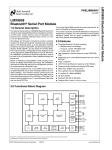
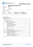
2.
HARDWARE DESCRIPTION
Gnd
U
S
B
Serial clock CLK
Serial Data IO
USB controller
Reset
Test
+5V USB
power
I
S
P
Switch
control
DC/DC stage
DC regulator
Vpp/Vreg
SWITCHES
Vdd/Vbat
Figure 1 : Hardware
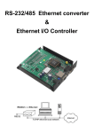
2.1
ISP CONNECTOR
The red mark shows the pin 1 (2.54mm HE10 2x5 pole male).
9
7
5
3
1
N.C.
Gnd
N.C.
Reset
Vdd/Vbat
Vpp/Vreg
Sclk
Sdio
Test
N.C.
10
8
6
4
2
Table 2 : ISP pinout
The ISP cable has to be connected here
2.2
USB CONNECTOR
It uses a female B-Mini 5 poles SMD connector.
The USB cable must be connected here
2.3
ISP CABLE
The red mark shows the pin 1.
The ISP flex cable is a 1:1 cable. It uses two female connector (2.54mm
HE10 2x5 pole female).
ISP cable must be connected between the ISP connector and the
application connector, demo board …
2.4
ELECTRICAL CONSIDERATIONS
Since the EMPB2 deliver power during programming, it is understood that the power is limited and it is
not possible to deliver an important current. User must not exceed the following limitations:
This document is the property of EM MICROELECTRONIC-MARIN SA and is furnished in confidence and upon the condition that all rights originating
in the information, whether patented or not, will be respected.
EM Document Center / rev. C-08.06 - Page 4 of 9
EMPB2 USER MANUAL
Parameter Maximum value
Unit
Vpp/Vreg
10
Vdd/Vbat
10
mA
Sdio
5
Sclk
5
Test
5
Reset
5
Table 3 : Maximum DC ratings
Connections to the dedicated programming pins (power and signals) must be done carefully.
No power-supply from the target board must be applied during the time of the EMPB2
connections. Disconnect the application power-supply before connecting the EMPB2.
If the application sink a significant part of the maximum rating current (Table 3 : Maximum DC
ratings), disconnect the application.
If communication lines (Sdio, Sclk) are used in the applications as general IOs you must
ensure that load on the lines will not be too important. Eventually and if possible, add some
serial resistors between the lines and the application and connect directly the programming
pins to the communications lines without resistors.
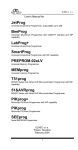
2.5
DEVICE CONNECTIONS
EM6503 - EM6504 - EM6505 - EM6517 - EM6520 - EM6521 - EM6522 - EM6540 required
connections:
9
7
5
3
1
Vss
Reset
Vdd
Vreg
Sclk(Qout)
Sdio(Qin)
Test
10
8
6
4
2
Vpp/Vreg
Sclk(PA4)
Sdio(PA0)
Test(PA1)
10
8
6
4
2
Vpp/Test
Sclk(PB5)
Sdio(PB7)
10
8
6
4
2
EM6580 required connections:
9
7
5
3
1
Vss
Vdd
EM6812 required connections:
9
7
5
3
1
2.6
Vss
Vdd
NOTE CONCERNING EM6580
A special option “Disable sector 2 verification” (/N option in command line mode) allows to handle
EM6580 without checking the content of sector 2 (refer to EM6580 Datasheet paragraph 15.2
Oscillator Trimming for more information). If this option is not selected (verification enabled means that
EMPB2 verify the content of sector 2 which contain trimming values) the content of sector 2 is written
and saved in a file located under EMPB2 installation folder (lastsector2.bin).
This document is the property of EM MICROELECTRONIC-MARIN SA and is furnished in confidence and upon the condition that all rights originating
in the information, whether patented or not, will be respected.
EM Document Center / rev. C-08.06 - Page 5 of 9
EMPB2 USER MANUAL
3.
SOFTWARE DESCRIPTION
3.1
INSTALLATION PROCEDURE
Do Not connect the EMPB2
Double-click on the executable file EMPBVxxx.exe and follow the steps.
After installation procedure, the USB driver must now be installed.
Open the EMPB2 software (shortcut in your Start menu). The following window appear
Connect EMPB2 to the USB cable and USB cable to your PC
New hardware will be detected, then by double-clicking on the New Hardware Found (USB
detection tip in your task bar), the following window appear
Check the “Install from a list or specific location” option and click next. The following window
appear
This document is the property of EM MICROELECTRONIC-MARIN SA and is furnished in confidence and upon the condition that all rights originating
in the information, whether patented or not, will be respected.
EM Document Center / rev. C-08.06 - Page 6 of 9
EMPB2 USER MANUAL
Check the “Include this in the search” option and through the Browse menu go to the root EMPB2
directory and select EMpb2Driver (it contains the .inf file). Click next. The following Window may
appear
Click Continue Anyway
The installation procedure is finished
This document is the property of EM MICROELECTRONIC-MARIN SA and is furnished in confidence and upon the condition that all rights originating
in the information, whether patented or not, will be respected.
EM Document Center / rev. C-08.06 - Page 7 of 9
EMPB2 USER MANUAL
3.2
EMPB2 SOFTWARE - GUI
The selection of the Device is done through the device combo-box.
The selection of the programming file is done through the Browse menu. Two formats are
supported (pure binary file *.bin or IntelHEX *.hex).
File Checksum is the checksum evaluated from the programming file.
Program action will realize the programming and CRC check. Device checksum return the
value of the CRC read from the device (File and device checksum must be identical for a
successful programming).
Verify action realize a CRC check
3.3
EMPB2 SOFTWARE – COMMAND LINE
EMPB2 can also be started from command line (DOS or any application). The following command line
is described below:
EMPB2 [/C] [/N] [/?|/H|/Help] [/M <MCU Type>] [/F <file to program>]
/C
Return the CRC as returned value if successful otherwise it return code error
Note: If no /C option return value is 0 if successful otherwise it return code error
/N
Don’t check sector 2 content if any (EM6580)
/?, /H or /Help
Open a help message box with
/M <MCU name>
The name of the MCU (EM6580, EM6812-2K, …)
/F <Prog. File>
The FULL path of the file to program (including extension .bin or .hex
This document is the property of EM MICROELECTRONIC-MARIN SA and is furnished in confidence and upon the condition that all rights originating
in the information, whether patented or not, will be respected.
EM Document Center / rev. C-08.06 - Page 8 of 9
EMPB2 USER MANUAL
/S
Start EMPB2 without any Graphical view
Note: if no /S only the scroll bar appears
The Returned Code or Errors are given below:
0
-1
-2
-3
-4
-5
-6
-7
-8
4.
Success
Unknown MCU name
BIN/HEX File not found or read error
Read Sector2 failed
Programming failed (sector 1 for EM6580)
Programming sector2 failed
Sector2 verification failed
Read CRC failed
Wrong CRC
KNOWN LIMITATION, BUGS, TROUBLESHOOTING
This document is the property of EM MICROELECTRONIC-MARIN SA and is furnished in confidence and upon the condition that all rights originating
in the information, whether patented or not, will be respected.
EM Document Center / rev. C-08.06 - Page 9 of 9


![Final Report - [Almost] Daily Photos](http://vs1.manualzilla.com/store/data/005658230_1-ad9be13b69bd4f2e15f58148160b0f22-150x150.png)