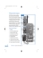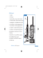
1
373-0761_revA_PC_Control
06/21/12
Page i
PCW Control
12 Station Residential Irrigation System Controller
Installation and Setup Guide
A comprehensive PCW Control system programming guide is included on the
software installation CD. Be sure to copy the file to your computer for quick reference.
373-0761_revC_PCW_Control
06/21/12
Page ii
Table of Contents
Page
PCW Control System Overview . . . . . . . . . . . . . . . . . . . . . . . . . . . . . . . . . . . . . . . . . .1
PCW Control System Components. . . . . . . . . . . . . . . . . . . . . . . . . . . . . . . . . . . . . . . .2
Getting Started . . . . . . . . . . . . . . . . . . . . . . . . . . . . . . . . . . . . . . . . . . . . . . . . . . . . . .4
Controller Installation . . . . . . . . . . . . . . . . . . . . . . . . . . . . . . . . . . . . . . . . . . . . . . . . .7
Controller Field Wire Connections . . . . . . . . . . . . . . . . . . . . . . . . . . . . . . . . . . . . . . . .8
Rain Sensor Installation . . . . . . . . . . . . . . . . . . . . . . . . . . . . . . . . . . . . . . . . . . . . . . .10
Landscape Lighting Installation . . . . . . . . . . . . . . . . . . . . . . . . . . . . . . . . . . . . . . . . .11
Testing the System . . . . . . . . . . . . . . . . . . . . . . . . . . . . . . . . . . . . . . . . . . . . . . . . . .12
PCW Control Program Installation. . . . . . . . . . . . . . . . . . . . . . . . . . . . . . . . . . . . . . . 13
Testing System Communication . . . . . . . . . . . . . . . . . . . . . . . . . . . . . . . . . . . . . . . .14
Hardware Specifications . . . . . . . . . . . . . . . . . . . . . . . . . . . . . . . . . . . . . . . . . . . . . . .16
Input Power Connection Cautionary Information . . . . . . . . . . . . . . . . . . . . . . . . . . .17
FCC Information . . . . . . . . . . . . . . . . . . . . . . . . . . . . . . . . . . . . . . . . . . . . . . . . . . . .18
ii
PCW Control
Table of Contents
373-0761_revA_PCW_Control
06/08/12
Page 1
PCW Control System Overview
What’s Included in your Irritrol PCW Control system package:
Software Installation CD – An auto-loading compact disk provides the PCW Control program
software, the install guide, and the complete user manual.
System Controller – A 12-station irrigation and landscape lighting controller with built-in
radio transceiver. Available in indoor and outdoor models. Includes 9V Alkaline battery and
installation hardware.
PCW-R (PC Remote) - A dual-function handheld remote transceiver to upload PCW Control
program information to the system Controller, and to provide wireless remote control
capability for manual system operations. Includes 9V Alkaline battery, desk stand and USB
cable.
Minimum Computer System Requirements:
Windows® compatible PC running Microsoft® Windows versions: XP, Vista, or Windows 7
Must have Microsoft .NET 3.5 Framework
Available USB port (version 1.1 or higher)
900 MHz CPU
CD-ROM drive
64MB RAM
20MB hard disk free space
1024 x 768 pixels, 64K color monitor
Keyboard and pointing device (mouse)
Internet connectivity (high-speed).
PCW Control
System Overview
1
373-0761_revA_PCW_Control
06/21/12
Page 2
PCW Control System Components
The PCW Control system is available in
indoor and outdoor Controller models.
The indoor model is designed for installation
in a sheltered location and is powered by a
24 VAC plug-in transformer. The outdoor
model incorporates a weather-resistant
cabinet with lockable front cover and built-in
24 VAC transformer. The outdoor models
require a grounded 120 or 230 VAC
hardware connection (depending on model).
System Controller (Figure 1)
1 - Antenna
2 - Station/Zone Indicator Lights
3 - Operation Indicator Lights
4 - Auto/Manual Control Buttons
5 - Wire Connection Terminals
6 - 9V Alkaline Battery
7 - 24 VAC Transformer (indoor)
8 - 120 VAC Power Wires (outdoor)
9 - 230 VAC Power Terminals (outdoor)
10 - Power Connection Cover (outdoor)
2
PCW Control
Figure 1
1
10
WARNING
WARNING
HIGH VOLTAGE
HIGH VOLTAGE
9
2
8
3
4
7
System Controller Components
5
6
373-0761_revA_PCW_Control
06/21/12
Page 3
PCW-R (Figure 2)
Figure 2
1 - Antenna
2 - LCD Screen
1
3 - Up Arrow Button - Increase station #/run time
4 - Down Arrow Button - Decrease station #/run time
5 - Lighting Button - Turn lighting station(s) On/Off
6 - Auto Off Button - Turn Auto program cycle Off
2
7 - Auto On Button - Turn Auto program cycle On
8 - Stop Button - Stop manual watering operation
11
9 - Start Button - Start manual watering operation
3
9
4
8
10 - Shuttle Button - Select station # or run time
11 - Belt Clip
10
12
7
13
13 - 9 Volt Alkaline Battery Connector
14 - USB Cable - Connect PCW-R to computer
6
STOP
AUTO
ON
12 - Mini USB Port - Connect PCW-R to computer
5
START
AUTO
OFF
Remote
14
15
15 - PCW-R Stand
Remote
PCW Control
PC-R Components
3
373-0761_revA_PCW_Control
06/21/12
Page 4
Getting Started
The PCW Control provides wireless two-way data transmission up to 1000’ (25.4m) LOS (line-ofsight). LOS is an industry standard used to determine the maximum effective range of a radio signal
when measured in a straight line without obstructions. Since perfect conditions rarely exist in typical
installations, a simple test to confirm signal reception must be performed prior to installing the
system controller in its permanent location.
To perform the communication test, prepare the
Figure 3
9V Alkaline
PCW Control system components as follows:
Screwdriver
Battery
1 – Install the PC-R battery.
Battery
Unlatch and remove the battery compartment
Cover
cover using a small common screwdriver.
Battery Clip
See Figure 3.
Attach the battery clip to the 9V Alkaline
battery (provided). Carefully stow the battery
and wires and reinstall the cover.
Figure 4
2 – Remove the Controller cabinet access cover.
Apply even pressure on both sides of the cover
at the location shown in Figure 4. When the
cover releases, pull it straight out from the
cabinet to remove.
3 – At the intended installation site, install a screw
or nail into the wall to temporarily mount the
Controller using the keyhole slot.
4
PCW Control
Getting Started
Keyhole
Slot
373-0761_revA_PCW_Control
06/21/12
Page 5
IMPORTANT: Ensure the transformer is unplugged or
Figure 5
AC input power source is off prior to making power
Green-Ground
wire connections. See page 17 for important safety
Black-24 VAC
information before continuing.
Red-24 VAC
4 – Connect the Controller power wiring.
Indoor model
Insert the transformer power cable into the controller
through the 1⁄4” access hole. See Figure 5.
Tie a knot about 6” from the end of the cable to
provide a cable strain-relief.
Using a small screwdriver, secure the power wires to the
corresponding RED, BLACK and EAR GND terminals.
Outdoor models
Remove the wiring compartment access cover secured
Figure 6A
Figure 6B
by two Phillips screws. (Refer to Figure 1).
Route 14 AWG (2mm2) hot (line), neutral and
equipment ground wires to the Controller.
120 VAC (Figure 6A) – Using twist-on wire
connectors, secure wires as follows: hot to black,
neutral to white and equipment ground to green.
230 VAC (Figure 6B) – Using a 3.2mm common
screwdriver, secure line to L, neutral to N and
equipment ground to .
5 – Apply power to the Controller. After 10 seconds, confirm the Power indicator is illuminated.
PCW Control
Getting Started
5
373-0761_revA_PCW_Control
06/21/12
Page 6
6 – While holding the PCW-R near the controller, turn on (”Wake up”) the
Figure 7
PCW-R by momentarily pressing any of its buttons. All display
elements will be shown during the initial wake up period. See Figure 7.
To turn off the PCW-R, press and hold the STOP button, then release
the button when OFF is displayed. To conserve battery power, the
PCW-R will turn off automatically if not used for an extended period.
7 – The antenna symbol and SENDING will be shown
as the PCW-R scans for the controller. When a link is
established, the antenna symbol (with signal bars)
and AUTO will be displayed. See Figure 8.
6
Figure 8
If communications is not established, the display will
prompt NO SIGNAL NOT ACCEPTED. This condition is generally
caused by a PIN code mismatch between the PCW-R and the Controller
(the default PIN code is 0000). Refer to “Setting PIN Code” in the PCW
Control user’s guide to help resolve the problem. See Figure 9.
8 – With communications established, send a test command to the
OFF
Controller by pressing the Auto Off AUTO
button. If the test is successful,
SENDING, ACCEPTED and OFF will be displayed.
Figure 10
The Controller’s Auto On indicator will turn off.
See Figure 10.
9 – With communication and remote operation at close
range confirmed, repeat the same procedure with
the PCW-R at the PCW Control system’s computer/
base station location.
PCW Control
Getting Started
Figure 9
373-0761_revA_PCW_Control
06/21/12
Page 7
10– If the communications check is satisfactory, disconnect power to the Controller and complete
the remaining installation and setup procedures. If communications is not established, try
repositioning the Controller slightly higher and/or moving it to a different location. Continue
to retest until two-way communications is confirmed.
Controller Installation
1 – If possible, locate a wall stud to anchor the Controller mounting screws. Install the top screw at
eye level, leaving approximately 1/4" (10mm) gap between the screw head and wall. If a wall
stud is not accessible, screw anchors must be used. Install the screw anchors at 5.25” (13.3cm)
on center.
2 – Mount the cabinet on the wall using the keyhole slot.
Figure 11
Ensure the cabinet is completely seated on the screw.
Adjust the screw depth as needed to achieve a good fit.
3 – Align the cabinet vertically and install the lower screw.
4 – Install electrical conduit as needed. Use 1/2" (13mm) conduit
for power wires (outdoor models) and 3/4" or 1" (19mm or
25mm) conduit for field wires. For 3/4" (19mm) conduit,
remove the inner knock-out ring only. For 1" (25mm)
5.25"
(13.3cm)
conduit, remove both knock-out rings.
5 – With power wires reconnected, reinstall Power connection
cover and secure with two Phillips screws (Outdoor model).
6 – Attach 9V Alkaline battery (provided) to battery clip and stow
in lower cabinet compartment.
PCW Control
Controller Installation
7
373-0761_revA_PCW_Control
06/21/12
Page 8
Controller Field Wire Connections
Direct-burial irrigation cable is recommended for valve and auxiliary relay (field) wire connections. The
appropriate wire diameter is determined by the length of the wire run between the Controller and the
point of connection. In most installations, wire runs up to 1000' (91m) can use 18 AWG (1.0mm2).
For wire runs up to 2000', 14 AWG (2.4mm2) is recommended. The number of wires or cable strands
required is determined by the number of field connections. Each valve or relay requires an individual
control wire and connection to a common wire. For example, if connecting 9 irrigation valves, 1
master valve, 2 outdoor lighting relays and a common wire, 13 wires or a 13-strand cable will be
needed.
1 – Route the wiring from the field connection point to the Controller. If conduit is installed, pull
the wiring through the conduit into the cabinet. Without conduit, simply insert the wiring
through the largest opening in the base of the cabinet. Leave approximately 10" (24.5cm) of
insulated wiring inside the cabinet for terminal connections.
2 – At the valve or relay, connect a separate control wire to either of the valve solenoid leads or
24 VAC relay terminals (or input wires).
3 – Interconnect all remaining solenoid leads and 24 VAC relay terminals to a single common
wire. The White color-code is generally used to identify the common wire.
4 – Protect and insulate each field wire connection from moisture and corrosion by installing
waterproof wire connectors. For reference during the remaining installation and setup
procedures, make a note of the wire insulation color used for each field connection and its
associated watering or lighting zone.
5 – At the controller, carefully remove 10" (25.4cm) of cable sheath (if applicable). Carefully strip
insulation back 1/4" (6mm) from the ends of each wire to be connected.
8
PCW Control
Controller Field Wire Connections
373-0761_revA_PCW_Control
06/21/12
Page 9
6 – Referring to the wiring diagram below, connect the valve common and control wires to the
controller terminals as shown. If a master valve or pump start relay is used, connect the
control wire to the MV terminal and common wire to the valve common terminal.
Figure 12
12 11 10 9
8
7
9
COM MV 1
OR
MV
2
3
4
5
1
8
7
6
2
3
4
5
6
Pump Start Relay or Master Valve
(See “Hardware Specifications” on page 17 for relay requirements.)
PCW Control
Controller Field Wire Connections
9
373-0761_revA_PCW_Control
06/21/12
Page 10
Rain Sensor Installation (optional)
The Sensor circuit is designed for a normally closed rain sensor. With the exception of the CLIMATE
LOGIC® weather-sensing system, all other Irritrol rain sensors are compatible with the PCW Control
system and are recommended for optimum reliability and ease of installation. The following steps
describe how to connect an Irritrol RS1000 Wireless RainSensor Receiver.
1 – Disconnect power to the Controller.
2 – Install the RainSensor hardware according to the instructions provided with the product.
3 – Use a common screwdriver to remove the
1/2" (13mm) accessory hole plug provided
on the bottom of the Controller cabinet.
4 – Insert the RainSensor Receiver cable. Loosen
the Sensor terminal screws (labeled SH and SL)
and remove the jumper wire. Connect the
Brown and White wires to the terminals in
either position. Connect the Red power wires
to the Black and Red 24 VAC input power
terminals. See Figure 13. (For clarity, input
power wires are not shown.)
Refer to RainSensor and PCW Control System
User's Guides for RainSensor setup and
operation.
10
PCW Control
RainSensor Installation
Figure 13
Brown
White
Red
Red
Jumper
373-0761_revA_PCW_Control
06/21/12
Page 11
Landscape Lighting Connection (optional)
Landscape lighting can be controlled through the use of a relay circuit connected to any station
output terminal.
A 24 VAC relay must be used to connect the Controller to the lighting system. The Irritrol SR-1
Pump Start Relay is ideal for lighting control and is recommended for this installation.
1 – Install the Pump Start Relay (or compatible relay system) according to the instructions
provided with the product.
2 – Connect a wire pair to White relay control wires and route them into the Controller.
See Figure 14.
3 – Connect one wire to the valve common terminal and one to the desired station number terminal.
Refer to PCW Control System User's Guides for lighting station setup and programming.
Figure 14
SR-1 Pump
Start Relay
Lighting
Transformer
Lighting
Fixtures
Yellow
12 VDC
PCW Control
120 VAC
Blue
Landscape Lighting Connection
White
120 VAC
Junction Box
11
373-0761_revA_PCW_Control
06/21/12
Page 12
Testing the System
Operation of the Controller and irrigation system can be tested using the PCW-R prior to installing
and setting up the PCW Control software program.
1 - Verify that the Controller’s Power, Signal and Auto On indicators are
on See Figure 15.
Figure 15
2 - Press any of the PCW-R buttons to wake it up, then press the
or
button (once only) to select the Manual mode. By default, Station 1 is
selected with a 10-minute run time. See Figure 16.
To change the station number, press
or
button.
To change the run time, press the
digits (flashing when selected).
button to select the time
To adjust the duration (1 minute to 4 hours), press the
or
button. (The adjusted run time will become the default run time
for all stations during this operation.)
3 - Press the
STAR T
button to begin operation. The
Figure 17
Manual and active Station Indicators will
illuminate. The water droplet symbol will flash
during operation. When the run time counts down
to 00, the station will turn off. See Figure 17.
To step through the station sequence during
manual operation, press the
button.
To terminate the manual operation, press the
12
PCW Control
Testing the System
STOP
button.
Figure 16
373-0761_revA_PCW_Control
06/21/12
Page 13
PCW Control System Program Installation
The PCW Control system installation CD will automatically install all of the necessary files onto the
computer hard disk. Prompts will be displayed during the installation process to enable various
options to be selected. Simply insert the CD into the disk drive and respond to the prompts as
required.
1 – Insert the CD into your computer disc drive.
2 – Double click on Setup.exe. The setup procedure will check and install the proper Microsoft
framework to properly run the PCW Control application before installing the PCW Control user
interface. Respond to the prompts as required.
Figure 18
Figure 19
The default folder location can
be modified to your prefered
program folder location.
PCW Control
Program Installation
13
373-0761_revA_PCW_Control
06/21/12
Page 14
PCW Remote (PCW-R) Quick Setup
Figure 20
The PC controller communicates with your
computer using the PC-R device. In order for
the software to recognize the PC-R device,
verify that the device is connected to the USB
port before launching the PCW Control
software.
1 – Connect the PCW-R to your computer using the provided USB cable.
2 – Launch the PCW Control program located in the PCW Control folder in your Program menu.
3 – Select New Site from the Quick Start window to create a new schedule.
4 – At the New Site window, specify the schedule’s name on the top text field (i.e., “My Yard”).
5 – At the PIN Number field, leave the default 0000 PIN or specify a four digit pin number for
the controller. When specifying a PIN other than 0000, the “Auto Sync Controller with New
PIN” must be checked. This PIN is used by the PCW-R to identify the controller. This is
important for systems with multiple controllers so the PCW-R will be able to send
commands/data to the intended controller.
6 – Specify the number of controllers and the number of zones each controller will have.
7 – At the prompt “Would you like to create from existing hardware”, click No if you want to
retain the number of zones you specified. If you click Yes, the system will automatically
detect the number of available zones in the controller.
The progress bar should appear at the top status bar to indicate that the PCW-R and the
controller have established good communication.
14
PCW Control
Testing System Communications
373-0761_revA_PC_Control
06/21/12
Page 15
8 – At the Get Schedule prompt, selecting Yes will command the controller to populate the
schedule with the default values of 10-minute daily watering per zones and sequentially
activating them starting at 6 am. If the controller have been previously programmed with a
schedule, the previous running times and starting times will be retrieved.
Selecting No at the Get Schedule prompt will return a blank schedule.
Retrieving the schedule data from the
controller might take as little as a few
minutes to an hour depending on the
complexity of the program.
Figure 21
9 – At the New Schedule Name prompt,
you can verify and modify the schedule
name according to your preference
(i.e., “Summer Schedule”).
10– Once the watering schedule is
established, you can modify the zone
parameters by adjusting the values in
the Time Slot section.
In order to increase watering duration
of a zone, it might be necessary to adjust
the other zones’ start time to accomodate for the longer run time.
11 – Add and delete a zone by selecting clicking Add or Delete buttons located at the bottom
right side of the window. When deleting a zone, verify that the correct zone is selected.
PCW Control
Testing System Communications
15
373-0761_revA_PCW_Control
06/21/12
Page 16
Hardware Specifications
Controller:
Operating Temperature Range: 14°F to 140°F (-10°C to 60°C)
Storage Temperature Range: -22°F to 149°F (-30°C to 65°C)
Class 2 transformer, grounded, UL Listed and CSA Certified
Input Power: 120 VAC, 60 HZ or 230 VAC, 50 Hz (International model)
Output Voltage: 24 VAC, 1.25A (30VA)
Maximum output per Station: 0.50A at 24 VAC
Maximum output per Pump Start/Master Valve: 0.50A at 24 VAC
Battery: 9V Alkaline
Auxiliary Relay Rating: 0.50A (max.) at 24 VAC
Maximum total output: 1.20A at 24 VAC (two stations and PS/MV on simultaneously)
Height (including antenna): 12.125" (Indoor model)
13.25" (33.7cm) (Outdoor model)
Width: 6.125" (Indoor model)
7.50" (19cm) (Outdoor model)
Depth: 3.00" (Indoor model)
4.75" (12cm) (Outdoor model)
PCW-R:
Height: 9.675" (24.6cm) (includes antenna and stand)
Width: 3" (7.6cm)
Depth: 1.5" (3.8cm)
Battery: 9V Alkaline
16
PCW Control
Hardware Specifications
373-0761_revA_PC_Control
06/21/12
Page 17
Input Power Cautionary Information
WARNING:
AC power wiring must be installed and connected by qualified personnel only. All electrical
components and installation procedures must comply with all applicable local and national
electrical codes. Some codes may require a means of disconnection from the AC power
source (circuit breaker) installed in the fixed wiring and having a contact separation of at
least 0.120" (3mm) in the line and neutral poles.
Make sure the power source is OFF prior to making wire connections. Do not apply power to
controller until all connections have been made per the installation instructions.
PCW Control
Input Power Cautionary Information
17
373-0761_revA_PCW_Control
06/21/12
Page 18
FCC Information
This equipment generates and uses radio frequency energy and if not installed and used properly,
that is, in strict accordance with the manufacturer's instructions, may cause interference to radio
and television reception. It has been type tested and found to comply with the limits for a FCC
Class B computing device in accordance with the specifications in Subpart J of Part 15 of FCC
Rules, which are designed to provide reasonable protection against such interference in a
residential installation. However, there is no guarantee that interference will not occur in a
particular installation. If this equipment does cause interference to radio or television reception,
which can be determined by turning the equipment off and on, the user is encouraged to try to
correct the interference by one or more of the following measures:
• Reorient the receiving antenna
• Relocate the irrigation controller with respect to the receiver
• Move the irrigation controller away from the receiver
• Plug the irrigation controller into a different outlet so that the irrigation controller and receiver
are on different branch circuits.
If necessary, the user should consult the dealer or an experienced radio/television technician for
additional suggestions. The user may find the following booklet prepared by the Federal
Communications Commission helpful: "How to Identify and Resolve Radio-TV Interference
Problems."This booklet is available from the U.S. Government Printing Office, Washington, DC
20402. Stock No. 004-000-00345-4.International: This is a CISPR 22 Class B product.FCC ID:
OF7RTS1IC: 3575A-RTS1
© 2012 Irritrol • www.irritrol.com
Form number 373-0761 Rev. A